WO2016194464A1 - Disjoncteur sous vide - Google Patents
Disjoncteur sous vide Download PDFInfo
- Publication number
- WO2016194464A1 WO2016194464A1 PCT/JP2016/060998 JP2016060998W WO2016194464A1 WO 2016194464 A1 WO2016194464 A1 WO 2016194464A1 JP 2016060998 W JP2016060998 W JP 2016060998W WO 2016194464 A1 WO2016194464 A1 WO 2016194464A1
- Authority
- WO
- WIPO (PCT)
- Prior art keywords
- fixed
- circuit breaker
- vacuum
- insulating
- vacuum valve
- Prior art date
- Legal status (The legal status is an assumption and is not a legal conclusion. Google has not performed a legal analysis and makes no representation as to the accuracy of the status listed.)
- Ceased
Links
Images


Classifications
-
- H—ELECTRICITY
- H01—ELECTRIC ELEMENTS
- H01H—ELECTRIC SWITCHES; RELAYS; SELECTORS; EMERGENCY PROTECTIVE DEVICES
- H01H33/00—High-tension or heavy-current switches with arc-extinguishing or arc-preventing means
- H01H33/60—Switches wherein the means for extinguishing or preventing the arc do not include separate means for obtaining or increasing flow of arc-extinguishing fluid
- H01H33/66—Vacuum switches
- H01H33/666—Operating arrangements
-
- H—ELECTRICITY
- H01—ELECTRIC ELEMENTS
- H01H—ELECTRIC SWITCHES; RELAYS; SELECTORS; EMERGENCY PROTECTIVE DEVICES
- H01H33/00—High-tension or heavy-current switches with arc-extinguishing or arc-preventing means
- H01H33/60—Switches wherein the means for extinguishing or preventing the arc do not include separate means for obtaining or increasing flow of arc-extinguishing fluid
- H01H33/66—Vacuum switches
- H01H33/6606—Terminal arrangements
-
- H—ELECTRICITY
- H01—ELECTRIC ELEMENTS
- H01H—ELECTRIC SWITCHES; RELAYS; SELECTORS; EMERGENCY PROTECTIVE DEVICES
- H01H33/00—High-tension or heavy-current switches with arc-extinguishing or arc-preventing means
- H01H33/60—Switches wherein the means for extinguishing or preventing the arc do not include separate means for obtaining or increasing flow of arc-extinguishing fluid
- H01H33/66—Vacuum switches
- H01H33/662—Housings or protective screens
-
- H—ELECTRICITY
- H01—ELECTRIC ELEMENTS
- H01H—ELECTRIC SWITCHES; RELAYS; SELECTORS; EMERGENCY PROTECTIVE DEVICES
- H01H33/00—High-tension or heavy-current switches with arc-extinguishing or arc-preventing means
- H01H33/60—Switches wherein the means for extinguishing or preventing the arc do not include separate means for obtaining or increasing flow of arc-extinguishing fluid
- H01H33/66—Vacuum switches
- H01H33/6606—Terminal arrangements
- H01H2033/6613—Cooling arrangements directly associated with the terminal arrangements
-
- H—ELECTRICITY
- H01—ELECTRIC ELEMENTS
- H01H—ELECTRIC SWITCHES; RELAYS; SELECTORS; EMERGENCY PROTECTIVE DEVICES
- H01H33/00—High-tension or heavy-current switches with arc-extinguishing or arc-preventing means
- H01H33/60—Switches wherein the means for extinguishing or preventing the arc do not include separate means for obtaining or increasing flow of arc-extinguishing fluid
- H01H33/66—Vacuum switches
- H01H33/666—Operating arrangements
- H01H2033/6665—Details concerning the mounting or supporting of the individual vacuum bottles
-
- H—ELECTRICITY
- H02—GENERATION; CONVERSION OR DISTRIBUTION OF ELECTRIC POWER
- H02B—BOARDS, SUBSTATIONS OR SWITCHING ARRANGEMENTS FOR THE SUPPLY OR DISTRIBUTION OF ELECTRIC POWER
- H02B13/00—Arrangement of switchgear in which switches are enclosed in, or structurally associated with, a casing, e.g. cubicle
- H02B13/02—Arrangement of switchgear in which switches are enclosed in, or structurally associated with, a casing, e.g. cubicle with metal casing
- H02B13/035—Gas-insulated switchgear
- H02B13/0352—Gas-insulated switchgear for three phase switchgear
-
- H—ELECTRICITY
- H02—GENERATION; CONVERSION OR DISTRIBUTION OF ELECTRIC POWER
- H02B—BOARDS, SUBSTATIONS OR SWITCHING ARRANGEMENTS FOR THE SUPPLY OR DISTRIBUTION OF ELECTRIC POWER
- H02B13/00—Arrangement of switchgear in which switches are enclosed in, or structurally associated with, a casing, e.g. cubicle
- H02B13/02—Arrangement of switchgear in which switches are enclosed in, or structurally associated with, a casing, e.g. cubicle with metal casing
- H02B13/035—Gas-insulated switchgear
- H02B13/0354—Gas-insulated switchgear comprising a vacuum switch
Definitions
- This invention relates to a vacuum circuit breaker mounted on a gas-insulated switchgear, and more particularly to a main circuit structure of a vacuum circuit breaker.
- the gas-insulated switchgear can reduce the size of the equipment due to the excellent insulation performance of sulfur hexafluoride (SF6) gas, and contributes to the reduction of the space in the electrical room.
- the vacuum circuit breaker mounted on this gas insulated switchgear is generally arranged such that the operation mechanism of the vacuum circuit breaker is arranged outside the gas container, and the main circuit part of the vacuum circuit breaker is arranged inside the gas container, The operation mechanism and the main circuit unit are configured to be coupled by a shaft that can be driven while keeping the inside and outside of the gas container airtight.
- the main circuit part of the vacuum circuit breaker is composed of an insulating operation rod, a movable side terminal, a vacuum valve and a fixed side terminal. It is necessary to support in the gas container while maintaining For this reason, the main circuit portion of the vacuum circuit breaker is generally configured to be supported by an insulator or an insulating holder in the gas container.
- the vacuum circuit breaker disclosed in Patent Document 1 the first insulating frame and the second insulating frame having a U-shaped cross section as shown in FIG.
- the first insulating frame and the second insulating frame are fastened by a fixed conductor of the vacuum valve.
- the vacuum circuit breaker disclosed in Patent Document 2 includes a pair of insulating support plates arranged so as to sandwich the vacuum valve from above and below, as shown in FIGS. 1 and 4, and one end of the insulating support plate. And an upper electrode fixed to the fixed side of the vacuum valve.
- JP 2013-149579 A Japanese Patent Laying-Open No. 2013-131440 (see particularly FIG. 3) JP 2013-149579 A (refer to FIGS. 1 and 4 in particular)
- the fixing plate that supports the fixed side of the vacuum valve is required to have strength to withstand the impact load generated in the main circuit when the vacuum circuit breaker is turned on or off, and a function to energize the main circuit of the vacuum circuit breaker. It is necessary to use a material with high current-carrying performance such as a thickness that can withstand impact loads. Therefore, there is a problem that the fixing plate is enlarged and the cost is increased.
- the present invention has been made to solve the above-described problems, and has a main circuit structure of a vacuum circuit breaker that is highly stable and can suppress cost without degrading withstand voltage performance and energization performance. The purpose is to obtain.
- the vacuum circuit breaker includes a vacuum valve having a fixed contact and a movable contact, a fixed terminal connected to the fixed contact of the vacuum valve, a movable terminal connected to the movable contact of the vacuum valve, and the vacuum valve
- a vacuum circuit breaker comprising: a main circuit structure including an insulating rod connected to the movable contact and configured to open and close the fixed contact and the movable contact; and an insulating holder supporting the main circuit structure.
- the holder is a frame structure having openings on the upper and lower surfaces and both side surfaces of the portion where the vacuum valve is disposed and the portion where the insulating rod is disposed.
- a vacuum circuit breaker capable of improving the withstand voltage performance and the energization performance around the vacuum valve of the circuit breaker can be provided at low cost.
- FIG. 6 is a diagram showing a cross-sectional shape along the line AA in FIG. 5.
- FIG. 6 is a diagram showing a cross-sectional shape along the line BB in FIG. 5.
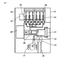
- FIG. 1 is a side sectional view showing a switch gear provided with a vacuum circuit breaker according to Embodiment 1 of the present invention
- FIG. 2 is a perspective view showing an insulating holder according to Embodiment 1 of the present invention.
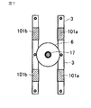
- 3 is a diagram showing a side shape of the insulating holder in FIG. 2
- FIG. 4 is a diagram showing a top shape of the insulating holder in FIG. 5 is a side view showing the structure of the single-pole portion of the vacuum circuit breaker according to Embodiment 1 of the present invention
- FIG. 1 is a side sectional view showing a switch gear provided with a vacuum circuit breaker according to Embodiment 1 of the present invention
- FIG. 2 is a perspective view showing an insulating holder according to Embodiment 1 of the present invention.
- 3 is a diagram showing a side shape of the insulating holder in FIG. 2
- FIG. 4 is a diagram showing a top shape of the insulating holder in FIG.
- FIG. 6 is a diagram showing a cross-sectional shape along the line AA in FIG.
- FIG. 6 is a diagram showing a cross-sectional shape along the line BB in FIG. 5;
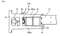
- FIG. 8 is a side view showing the main configuration of the vacuum circuit breaker according to Embodiment 1 of the present invention, and
- FIG. 9 is a plan view showing the top shape of the vacuum circuit breaker in FIG.
- the switch gear has a door DR, and a housing CS that houses each part, and a vacuum circuit breaker VB, an instrument current transformer CT, an instrument transformer VT provided in the casing CS, and A disconnector DS is provided.
- the vacuum circuit breaker VB has one terminal connected to the cable CB via the connection conductor CD and the cable head CH, and the other terminal connected to the horizontal bus HB.
- the vacuum circuit breaker VB has a current transformer CT and an instrument transformer VT connected to a path connected to the cable CB, and a disconnector DS connected to a path connected to the horizontal bus HB. Yes.
- the switch gear includes a disconnector operation mechanism part LP in which a disconnector operation mechanism for operating the disconnector DS is accommodated, and a breaker operation mechanism part BP in which a breaker operation mechanism for operating the vacuum circuit breaker VB is accommodated.
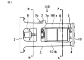
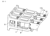
- the main circuit structure forming the vacuum circuit breaker VB includes a vacuum valve 8 having a fixed contact and a movable contact, and a fixed terminal 9 connected to the fixed contact of the vacuum valve 8 as shown in FIG.
- the movable side terminal 7a connected to the movable contact of the vacuum valve 8 and the insulating rod 6 connected to the movable contact of the vacuum valve 8 to open and close the movable contact are configured. It is fixed to the insulating holder 1 via the part 4.
- the vacuum valve 8 is provided with a fixed contact and a movable contact inside a vacuum vessel constituted by an insulating cylinder.
- the fixed contact of the vacuum valve 8 is fixed to the tip of the fixed electrode rod, and this fixed electrode rod is fixed to a fixed side end plate provided on one end face of the insulating cylinder.
- the movable contact is fixed to the tip of the movable electrode rod driven by the insulating rod 6, and an opening / closing operation with respect to the fixed contact is performed according to the movement of the movable electrode rod.
- the movable electrode bar passes through a movable side end plate provided on the other end surface of the insulating cylinder, and this penetrating portion is sealed by a sealing member made of a bellows.
- the fixed terminal 9 connected to the fixed contact is fixed to the fixed electrode rod, and the movable terminal 7a connected to the movable contact is fixed to the movable electrode rod.
- the insulating holder 1 is fixed to a movable conductor fixing portion 2 that fixes the movable conductor of the vacuum circuit breaker VB, a fixing portion 3 that fixes the insulating holder 1, and a main circuit structure. It comprises a fixed plate fixing part 4 for fixing the plate 10. More specifically, as shown in FIG. 4, the insulating holder 1 has a U-shaped frame 101 connected to the innermost end (right side in the figure) arranged in two upper and lower stages as shown in FIG.
- one side of the opening side 102 of the upper frame 101a of the frame 101 and one side of the opening side 102 of the lower frame 101b are integrally coupled by the insulating holder fixing portion 3 in the vertical direction, and the U-shaped upper frame 101a and lower frame 101b
- Each intermediate portion is configured as a frame structure integrally connected by a vertical intermediate frame 103.
- Such an insulating holder 1 is manufactured by integrally molding an insulating resin material.
- the insulating rod 6 is disposed in a space surrounded by the insulating holder fixing part 3 of the insulating holder 1, the intermediate frame 103, and the insulating holder fixing part side of the U-shaped frame 101, and the tips of the U-shaped frames 101a and 101b.
- the vacuum valve 8 is disposed in a space surrounded by the sides 104a and 104b and the intermediate frame 103, thereby forming a vacuum circuit breaker VB as shown in FIG. If there is a margin in strength, the intermediate frame 103 may be omitted.
- the insulating rod side opening 5a (see FIG. 3) is located at the position where the insulation rod 6 is disposed. ),
- the insulating rod upper surface opening 5b (see FIG. 4) is provided, and the vacuum valve side surface opening 5c (see FIG. 3) and the vacuum valve upper surface opening 5d (see FIG. 3) are provided at positions where the vacuum valve 8 is disposed. 4) will be provided.
- the movable side terminal 7a and the movable conductor 7b of the vacuum valve are attached to the movable side of the vacuum valve 8, and the movable conductor 7b is a movable conductor. Fastened to the fixed portion 2.
- a fixed side terminal 9 is attached to the fixed side of the vacuum valve 8, and the fixed side terminal 9 is fastened to the frame 101 of the insulating holder 1 via the fixed plate 10 and the fixed plate fixing portion 4.
- FIG. 6 shows a cross section along the line AA in FIG. 5, and the electrode 13, electrode rod 14, insulating cylinder (insulating cylinder) 15, and electrode shield 16 of the vacuum valve 8 arranged in the insulating holder 1. It is shown.
- FIG. 7 shows a cross section taken along line BB in FIG. 5, and shows the insulating rod 6 and the operating rod 17 of the vacuum valve 8 arranged in the insulating holder 1.
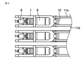
- FIG. 8 and 9 show examples applied to a three-phase vacuum circuit breaker VB
- FIG. 8 shows a state in which a fixed-side conductor 11 is attached to a vacuum valve fixed-side terminal 9 having a single-pole vacuum circuit breaker structure
- FIG. 9 shows a structure in which the fixed side conductor 11a and the fixed side conductor 11b are fastened to both side surfaces of one fixed side terminal 9 of the vacuum valve 8, and the wide portions are arranged in the vertical direction.
- the fixed side conductors 11 (11a, 11b) are directly attached to the both side surfaces of the fixed side terminal 9 of the vacuum circuit breaker VB without using the fixing plate 10 for fixing the vacuum valve 8 and the insulating holder 1.
- the current-carrying performance can be improved by increasing the area, and the fixed-side conductor 11a and the fixed-side conductor 11b, which are flat conductors, are arranged in the vertical (vertical) direction, so that the conductor does not hinder air convection.
- the heat dissipation performance of the part can also be improved.
- the example which uses two conductors (11a, 11b) as the fixed side conductor 11 was shown, when an energization current is not large, only one of them may be used.
- the insulating holder 1 is formed of a frame structure having openings on the top and side surfaces, a main circuit structure having high heat dissipation performance can be formed without hindering air convection around the vacuum valve 8. it can. Moreover, since the large opening is provided in the insulation holder 1, the bolt fastening operation
- the vacuum circuit breaker VB is a device that operates the movable electrode of the vacuum valve 8 and supplies or interrupts current
- the insulating holder 1 that supports the vacuum valve 8 is generated when the vacuum circuit breaker is turned on or opened.
- the strength that can withstand the impact load is required, and the fixing plate 10 that fixes the insulating holder 1 and the vacuum valve 8 also needs to have the strength to withstand the impact load.
- FIG. 8 the fixed plate 10 has a function of supporting the vacuum valve 8 withstanding the impact of the vacuum circuit breaker, and the fixed side terminal 9 is connected to the main circuit of the vacuum circuit breaker and has a function of supplying electricity.
- the side terminal 9 and the fixed plate 10 employ a configuration in which the functions of energization and strength are separated. Therefore, it is not necessary to use an expensive metal such as aluminum or copper having current-carrying performance, and the fixing plate 10 can be manufactured using an inexpensive metal such as iron.
- the fixing plate 10 since the fixing plate 10 is disposed between the end portions of the U-shaped frame 101, the fixing plate 10 has a size larger than the diameter of the vacuum valve 8 and needs to support the vacuum valve 8. In order to realize a sufficient strength, a necessary thickness is also required.
- the fixed plate 10 is large in size and bulky, for example, if an inexpensive material such as iron is used, an increase in cost can be suppressed.
- the fixed-side terminal 9 requires an expensive material having a current-carrying performance such as copper or aluminum. However, it is sufficient if the size is approximately the same as the diameter of the vacuum valve 8, and the material cost may be increased. Absent.
- FIG. 10 a vacuum circuit breaker that is a main part of the switchgear according to Embodiment 2 of the present invention will be described with reference to FIG.
- the radiating fins 12 are arranged between the fixed-side conductor 11a and the fixed-side conductor 11b of the main circuit structure of the vacuum circuit breaker. Since the other configuration excluding the heat radiating fin 12 is the same as that of the first embodiment, the description thereof is omitted.
- the radiating fin 12 is disposed in a space between the fixed side conductor 11a and the fixed side conductor 11b, the electric field around the radiating fin 12 is hardly increased, and the withstand voltage performance can be lowered. Absent.
- the fixed side terminal 9 is made of a metal having good conductivity
- the fixed plate 10 is made of inexpensive iron or the like, so that the functions of energization and strength are combined.
- both the fixed side terminal 9 and the fixed plate 10 are made of a metal having good current-carrying performance such as copper or aluminum, and the fixed side conductor 13 is directly fastened to the fixed plate 10. Also good.
- the cost of the main circuit structure increases as much expensive metal as copper or aluminum is used than iron, but the fixed conductor 13 is directly fastened to the fixed plate 10. It is possible to improve the assembly work efficiency.
- FIG. 2 is a plan view
- FIG. 3 is a side view
- the present invention can be freely combined with some or all of the embodiments, and each embodiment can be appropriately modified or omitted.
- Insulating holder 2 Movable conductor fixed part of vacuum circuit breaker
- 3 Insulation holder fixing part
- 4 Breaker fixing plate fixing part
- 5a Insulation rod side opening of vacuum circuit breaker main circuit
- 5b upper surface opening of insulating rod of vacuum circuit breaker main circuit
- 5c Vacuum valve side opening
- 5d Vacuum valve top opening
- 6 Insulating rod
- 7a Vacuum valve movable side terminal
- 7b movable conductor
- 8 vacuum valve
- 9 vacuum valve fixed side terminal
- 10 Fixed plate 11, 11a, 11b, 13: Fixed side conductor
- 12 radiating fin
- 101 U-shaped frame of insulating holder
- 103 Intermediate frame of insulating holder
Landscapes
- High-Tension Arc-Extinguishing Switches Without Spraying Means (AREA)
- Gas-Insulated Switchgears (AREA)
Abstract
Priority Applications (5)
| Application Number | Priority Date | Filing Date | Title |
|---|---|---|---|
| JP2016566292A JP6091729B1 (ja) | 2015-06-05 | 2016-04-04 | 真空遮断器 |
| US15/556,394 US10153110B2 (en) | 2015-06-05 | 2016-04-04 | Vacuum circuit breaker |
| CN201680031078.7A CN107615435B (zh) | 2015-06-05 | 2016-04-04 | 真空断路器 |
| EP16802901.5A EP3306636B1 (fr) | 2015-06-05 | 2016-04-04 | Disjoncteur sous vide |
| HK18105417.4A HK1245994B (zh) | 2015-06-05 | 2016-04-04 | 真空断路器 |
Applications Claiming Priority (2)
| Application Number | Priority Date | Filing Date | Title |
|---|---|---|---|
| JP2015-114378 | 2015-06-05 | ||
| JP2015114378 | 2015-06-05 |
Publications (1)
| Publication Number | Publication Date |
|---|---|
| WO2016194464A1 true WO2016194464A1 (fr) | 2016-12-08 |
Family
ID=57440891
Family Applications (1)
| Application Number | Title | Priority Date | Filing Date |
|---|---|---|---|
| PCT/JP2016/060998 Ceased WO2016194464A1 (fr) | 2015-06-05 | 2016-04-04 | Disjoncteur sous vide |
Country Status (6)
| Country | Link |
|---|---|
| US (1) | US10153110B2 (fr) |
| EP (1) | EP3306636B1 (fr) |
| JP (1) | JP6091729B1 (fr) |
| CN (1) | CN107615435B (fr) |
| HK (1) | HK1245994B (fr) |
| WO (1) | WO2016194464A1 (fr) |
Families Citing this family (4)
| Publication number | Priority date | Publication date | Assignee | Title |
|---|---|---|---|---|
| FR3070533B1 (fr) * | 2017-08-28 | 2019-09-13 | Schneider Electric Industries Sas | Pole de coupure de courant |
| CN108693389A (zh) * | 2018-08-22 | 2018-10-23 | 广东理工职业学院 | 一种框架式断路器耐压测试夹具 |
| CN114373652B (zh) * | 2022-01-20 | 2022-10-11 | 广东明阳电气股份有限公司 | 一种真空断路器用绝缘筒装置 |
| CN114496605B (zh) * | 2022-02-25 | 2023-09-22 | 阿科法电气有限公司 | 常压密封环网柜断路器开关 |
Citations (5)
| Publication number | Priority date | Publication date | Assignee | Title |
|---|---|---|---|---|
| JPS489967U (fr) * | 1971-06-03 | 1973-02-03 | ||
| JPS56109416A (en) * | 1980-02-04 | 1981-08-29 | Meidensha Electric Mfg Co Ltd | Vacuum switching device |
| JPS56128528A (en) * | 1980-03-11 | 1981-10-08 | Meidensha Electric Mfg Co Ltd | Conductor for large current vacuum switch |
| JPS58148842U (ja) * | 1982-03-31 | 1983-10-06 | 株式会社東芝 | 真空しや断器 |
| JP2002231112A (ja) * | 2001-02-06 | 2002-08-16 | Nissin Electric Co Ltd | 遮断器ユニット及び遮断器ユニット用絶縁支持枠 |
Family Cites Families (10)
| Publication number | Priority date | Publication date | Assignee | Title |
|---|---|---|---|---|
| JP2908554B2 (ja) * | 1990-11-19 | 1999-06-21 | 株式会社東芝 | 真空遮断器 |
| DE4419380C1 (de) * | 1994-05-30 | 1995-10-19 | Siemens Ag | Leistungsschaltermodul |
| JP4159938B2 (ja) * | 2003-07-25 | 2008-10-01 | 株式会社東芝 | モールド電気機器およびそのモールド方法 |
| JP4752678B2 (ja) * | 2006-08-25 | 2011-08-17 | 三菱電機株式会社 | 開閉装置 |
| US8237075B2 (en) * | 2008-04-07 | 2012-08-07 | Mitsubishi Electric Corporation | Vacuum circuit breaker and gas-insulated switchgear using the same |
| CN102165553B (zh) * | 2008-12-02 | 2014-09-03 | 三菱电机株式会社 | 电磁接触器 |
| JP5215238B2 (ja) * | 2009-05-28 | 2013-06-19 | 三菱電機株式会社 | 遮断器 |
| JP6094028B2 (ja) | 2011-12-22 | 2017-03-15 | 株式会社明電舎 | 真空遮断器 |
| JP2013149579A (ja) | 2012-01-23 | 2013-08-01 | Toshiba Corp | 真空遮断器 |
| EP2720245A1 (fr) * | 2012-10-15 | 2014-04-16 | ABB Technology AG | Partie polaire assemblée avec cadre de l'élément de pôle |
-
2016
- 2016-04-04 WO PCT/JP2016/060998 patent/WO2016194464A1/fr not_active Ceased
- 2016-04-04 HK HK18105417.4A patent/HK1245994B/zh unknown
- 2016-04-04 EP EP16802901.5A patent/EP3306636B1/fr active Active
- 2016-04-04 JP JP2016566292A patent/JP6091729B1/ja active Active
- 2016-04-04 CN CN201680031078.7A patent/CN107615435B/zh active Active
- 2016-04-04 US US15/556,394 patent/US10153110B2/en active Active
Patent Citations (5)
| Publication number | Priority date | Publication date | Assignee | Title |
|---|---|---|---|---|
| JPS489967U (fr) * | 1971-06-03 | 1973-02-03 | ||
| JPS56109416A (en) * | 1980-02-04 | 1981-08-29 | Meidensha Electric Mfg Co Ltd | Vacuum switching device |
| JPS56128528A (en) * | 1980-03-11 | 1981-10-08 | Meidensha Electric Mfg Co Ltd | Conductor for large current vacuum switch |
| JPS58148842U (ja) * | 1982-03-31 | 1983-10-06 | 株式会社東芝 | 真空しや断器 |
| JP2002231112A (ja) * | 2001-02-06 | 2002-08-16 | Nissin Electric Co Ltd | 遮断器ユニット及び遮断器ユニット用絶縁支持枠 |
Non-Patent Citations (1)
| Title |
|---|
| See also references of EP3306636A4 * |
Also Published As
| Publication number | Publication date |
|---|---|
| US20180047532A1 (en) | 2018-02-15 |
| EP3306636A1 (fr) | 2018-04-11 |
| JPWO2016194464A1 (ja) | 2017-06-15 |
| CN107615435A (zh) | 2018-01-19 |
| EP3306636A4 (fr) | 2019-01-02 |
| US10153110B2 (en) | 2018-12-11 |
| JP6091729B1 (ja) | 2017-03-08 |
| EP3306636B1 (fr) | 2023-12-06 |
| HK1245994B (zh) | 2020-04-17 |
| CN107615435B (zh) | 2019-03-15 |
Similar Documents
| Publication | Publication Date | Title |
|---|---|---|
| JP4764906B2 (ja) | 真空スイッチ及び真空スイッチギヤ | |
| CN101981645B (zh) | 真空断路器和采用该真空断路器的气体绝缘开关装置 | |
| JP6091729B1 (ja) | 真空遮断器 | |
| HK1245994A1 (en) | Vacuum circuit breaker | |
| US11348748B2 (en) | Switch device | |
| JP6094028B2 (ja) | 真空遮断器 | |
| WO2018229962A1 (fr) | Appareillage de commutation à isolation gazeuse | |
| JP4762802B2 (ja) | 真空スイッチギヤ | |
| JP5557794B2 (ja) | モールドスイッチ及びこれを搭載した装置 | |
| KR101246696B1 (ko) | 접지 차단기 및 이의 제조 방법 | |
| WO2011145749A1 (fr) | Appareil de commutation à isolant gazeux monté en armoire | |
| KR101569194B1 (ko) | 가스 절연 중전압 스위치기어 | |
| US9263200B2 (en) | High-current switching arrangement | |
| JP2004159415A (ja) | 真空開閉装置 | |
| JP7576190B2 (ja) | 開閉器 | |
| ES2943533T3 (es) | Compartimento de disyuntor | |
| WO2019171707A1 (fr) | Commutateur | |
| JP7293973B2 (ja) | ガス絶縁開閉装置 | |
| JP2019054638A (ja) | 接地開閉器・避雷器ユニットおよびガス絶縁開閉装置 | |
| CN102257688B (zh) | 气体绝缘开关 | |
| HK1197492B (en) | Vacuum circuit breaker | |
| HK1197492A (en) | Vacuum circuit breaker | |
| JPH04127810A (ja) | ガス絶縁開閉器 |
Legal Events
| Date | Code | Title | Description |
|---|---|---|---|
| ENP | Entry into the national phase |
Ref document number: 2016566292 Country of ref document: JP Kind code of ref document: A |
|
| 121 | Ep: the epo has been informed by wipo that ep was designated in this application |
Ref document number: 16802901 Country of ref document: EP Kind code of ref document: A1 |
|
| WWE | Wipo information: entry into national phase |
Ref document number: 15556394 Country of ref document: US |
|
| NENP | Non-entry into the national phase |
Ref country code: DE |
|
| WWE | Wipo information: entry into national phase |
Ref document number: 2016802901 Country of ref document: EP |