WO2016194718A1 - Appareil de traitement d'image, procédé de traitement d'image et système chirurgical - Google Patents
Appareil de traitement d'image, procédé de traitement d'image et système chirurgical Download PDFInfo
- Publication number
- WO2016194718A1 WO2016194718A1 PCT/JP2016/065387 JP2016065387W WO2016194718A1 WO 2016194718 A1 WO2016194718 A1 WO 2016194718A1 JP 2016065387 W JP2016065387 W JP 2016065387W WO 2016194718 A1 WO2016194718 A1 WO 2016194718A1
- Authority
- WO
- WIPO (PCT)
- Prior art keywords
- region
- image
- detection unit
- frequency
- unit
- Prior art date
- Legal status (The legal status is an assumption and is not a legal conclusion. Google has not performed a legal analysis and makes no representation as to the accuracy of the status listed.)
- Ceased
Links
Images







Classifications
-
- A—HUMAN NECESSITIES
- A61—MEDICAL OR VETERINARY SCIENCE; HYGIENE
- A61B—DIAGNOSIS; SURGERY; IDENTIFICATION
- A61B1/00—Instruments for performing medical examinations of the interior of cavities or tubes of the body by visual or photographical inspection, e.g. endoscopes; Illuminating arrangements therefor
- A61B1/00002—Operational features of endoscopes
- A61B1/00004—Operational features of endoscopes characterised by electronic signal processing
- A61B1/00009—Operational features of endoscopes characterised by electronic signal processing of image signals during a use of endoscope
- A61B1/000095—Operational features of endoscopes characterised by electronic signal processing of image signals during a use of endoscope for image enhancement
-
- A—HUMAN NECESSITIES
- A61—MEDICAL OR VETERINARY SCIENCE; HYGIENE
- A61B—DIAGNOSIS; SURGERY; IDENTIFICATION
- A61B1/00—Instruments for performing medical examinations of the interior of cavities or tubes of the body by visual or photographical inspection, e.g. endoscopes; Illuminating arrangements therefor
- A61B1/313—Instruments for performing medical examinations of the interior of cavities or tubes of the body by visual or photographical inspection, e.g. endoscopes; Illuminating arrangements therefor for introducing through surgical openings, e.g. laparoscopes
- A61B1/3132—Instruments for performing medical examinations of the interior of cavities or tubes of the body by visual or photographical inspection, e.g. endoscopes; Illuminating arrangements therefor for introducing through surgical openings, e.g. laparoscopes for laparoscopy
-
- A—HUMAN NECESSITIES
- A61—MEDICAL OR VETERINARY SCIENCE; HYGIENE
- A61B—DIAGNOSIS; SURGERY; IDENTIFICATION
- A61B17/00—Surgical instruments, devices or methods
- A61B17/34—Trocars; Puncturing needles
- A61B17/3417—Details of tips or shafts, e.g. grooves, expandable, bendable; Multiple coaxial sliding cannulas, e.g. for dilating
- A61B17/3421—Cannulas
- A61B17/3423—Access ports, e.g. toroid shape introducers for instruments or hands
-
- A—HUMAN NECESSITIES
- A61—MEDICAL OR VETERINARY SCIENCE; HYGIENE
- A61B—DIAGNOSIS; SURGERY; IDENTIFICATION
- A61B17/00—Surgical instruments, devices or methods
- A61B17/34—Trocars; Puncturing needles
- A61B17/3474—Insufflating needles, e.g. Veress needles
-
- A—HUMAN NECESSITIES
- A61—MEDICAL OR VETERINARY SCIENCE; HYGIENE
- A61B—DIAGNOSIS; SURGERY; IDENTIFICATION
- A61B18/00—Surgical instruments, devices or methods for transferring non-mechanical forms of energy to or from the body
- A61B18/04—Surgical instruments, devices or methods for transferring non-mechanical forms of energy to or from the body by heating
- A61B18/12—Surgical instruments, devices or methods for transferring non-mechanical forms of energy to or from the body by heating by passing a current through the tissue to be heated, e.g. high-frequency current
- A61B18/14—Probes or electrodes therefor
-
- A—HUMAN NECESSITIES
- A61—MEDICAL OR VETERINARY SCIENCE; HYGIENE
- A61B—DIAGNOSIS; SURGERY; IDENTIFICATION
- A61B5/00—Measuring for diagnostic purposes; Identification of persons
- A61B5/02—Detecting, measuring or recording for evaluating the cardiovascular system, e.g. pulse, heart rate, blood pressure or blood flow
- A61B5/02007—Evaluating blood vessel condition, e.g. elasticity, compliance
-
- A—HUMAN NECESSITIES
- A61—MEDICAL OR VETERINARY SCIENCE; HYGIENE
- A61B—DIAGNOSIS; SURGERY; IDENTIFICATION
- A61B5/00—Measuring for diagnostic purposes; Identification of persons
- A61B5/02—Detecting, measuring or recording for evaluating the cardiovascular system, e.g. pulse, heart rate, blood pressure or blood flow
- A61B5/02042—Determining blood loss or bleeding, e.g. during a surgical procedure
-
- A—HUMAN NECESSITIES
- A61—MEDICAL OR VETERINARY SCIENCE; HYGIENE
- A61B—DIAGNOSIS; SURGERY; IDENTIFICATION
- A61B5/00—Measuring for diagnostic purposes; Identification of persons
- A61B5/02—Detecting, measuring or recording for evaluating the cardiovascular system, e.g. pulse, heart rate, blood pressure or blood flow
- A61B5/024—Measuring pulse rate or heart rate
-
- A—HUMAN NECESSITIES
- A61—MEDICAL OR VETERINARY SCIENCE; HYGIENE
- A61B—DIAGNOSIS; SURGERY; IDENTIFICATION
- A61B5/00—Measuring for diagnostic purposes; Identification of persons
- A61B5/103—Measuring devices for testing the shape, pattern, colour, size or movement of the body or parts thereof, for diagnostic purposes
- A61B5/11—Measuring movement of the entire body or parts thereof, e.g. head or hand tremor or mobility of a limb
- A61B5/1126—Measuring movement of the entire body or parts thereof, e.g. head or hand tremor or mobility of a limb using a particular sensing technique
- A61B5/1128—Measuring movement of the entire body or parts thereof, e.g. head or hand tremor or mobility of a limb using a particular sensing technique using image analysis
-
- A—HUMAN NECESSITIES
- A61—MEDICAL OR VETERINARY SCIENCE; HYGIENE
- A61B—DIAGNOSIS; SURGERY; IDENTIFICATION
- A61B5/00—Measuring for diagnostic purposes; Identification of persons
- A61B5/48—Other medical applications
- A61B5/4887—Locating particular structures in or on the body
- A61B5/489—Blood vessels
-
- A—HUMAN NECESSITIES
- A61—MEDICAL OR VETERINARY SCIENCE; HYGIENE
- A61B—DIAGNOSIS; SURGERY; IDENTIFICATION
- A61B5/00—Measuring for diagnostic purposes; Identification of persons
- A61B5/72—Signal processing specially adapted for physiological signals or for diagnostic purposes
- A61B5/7271—Specific aspects of physiological measurement analysis
- A61B5/7285—Specific aspects of physiological measurement analysis for synchronizing or triggering a physiological measurement or image acquisition with a physiological event or waveform, e.g. an ECG signal
- A61B5/7289—Retrospective gating, i.e. associating measured signals or images with a physiological event after the actual measurement or image acquisition, e.g. by simultaneously recording an additional physiological signal during the measurement or image acquisition
-
- A—HUMAN NECESSITIES
- A61—MEDICAL OR VETERINARY SCIENCE; HYGIENE
- A61B—DIAGNOSIS; SURGERY; IDENTIFICATION
- A61B90/00—Instruments, implements or accessories specially adapted for surgery or diagnosis and not covered by any of the groups A61B1/00 - A61B50/00, e.g. for luxation treatment or for protecting wound edges
- A61B90/20—Surgical microscopes characterised by non-optical aspects
-
- A—HUMAN NECESSITIES
- A61—MEDICAL OR VETERINARY SCIENCE; HYGIENE
- A61B—DIAGNOSIS; SURGERY; IDENTIFICATION
- A61B90/00—Instruments, implements or accessories specially adapted for surgery or diagnosis and not covered by any of the groups A61B1/00 - A61B50/00, e.g. for luxation treatment or for protecting wound edges
- A61B90/36—Image-producing devices or illumination devices not otherwise provided for
- A61B90/361—Image-producing devices, e.g. surgical cameras
-
- A—HUMAN NECESSITIES
- A61—MEDICAL OR VETERINARY SCIENCE; HYGIENE
- A61B—DIAGNOSIS; SURGERY; IDENTIFICATION
- A61B90/00—Instruments, implements or accessories specially adapted for surgery or diagnosis and not covered by any of the groups A61B1/00 - A61B50/00, e.g. for luxation treatment or for protecting wound edges
- A61B90/36—Image-producing devices or illumination devices not otherwise provided for
- A61B90/37—Surgical systems with images on a monitor during operation
-
- G—PHYSICS
- G06—COMPUTING OR CALCULATING; COUNTING
- G06T—IMAGE DATA PROCESSING OR GENERATION, IN GENERAL
- G06T7/00—Image analysis
- G06T7/20—Analysis of motion
- G06T7/215—Motion-based segmentation
-
- A—HUMAN NECESSITIES
- A61—MEDICAL OR VETERINARY SCIENCE; HYGIENE
- A61B—DIAGNOSIS; SURGERY; IDENTIFICATION
- A61B17/00—Surgical instruments, devices or methods
- A61B2017/00017—Electrical control of surgical instruments
- A61B2017/00115—Electrical control of surgical instruments with audible or visual output
- A61B2017/00119—Electrical control of surgical instruments with audible or visual output alarm; indicating an abnormal situation
-
- A—HUMAN NECESSITIES
- A61—MEDICAL OR VETERINARY SCIENCE; HYGIENE
- A61B—DIAGNOSIS; SURGERY; IDENTIFICATION
- A61B17/00—Surgical instruments, devices or methods
- A61B2017/00681—Aspects not otherwise provided for
- A61B2017/00694—Aspects not otherwise provided for with means correcting for movement of or for synchronisation with the body
- A61B2017/00699—Aspects not otherwise provided for with means correcting for movement of or for synchronisation with the body correcting for movement caused by respiration, e.g. by triggering
-
- A—HUMAN NECESSITIES
- A61—MEDICAL OR VETERINARY SCIENCE; HYGIENE
- A61B—DIAGNOSIS; SURGERY; IDENTIFICATION
- A61B17/00—Surgical instruments, devices or methods
- A61B2017/00681—Aspects not otherwise provided for
- A61B2017/00694—Aspects not otherwise provided for with means correcting for movement of or for synchronisation with the body
- A61B2017/00703—Aspects not otherwise provided for with means correcting for movement of or for synchronisation with the body correcting for movement of heart, e.g. ECG-triggered
-
- A—HUMAN NECESSITIES
- A61—MEDICAL OR VETERINARY SCIENCE; HYGIENE
- A61B—DIAGNOSIS; SURGERY; IDENTIFICATION
- A61B17/00—Surgical instruments, devices or methods
- A61B2017/00973—Surgical instruments, devices or methods pedal-operated
-
- A—HUMAN NECESSITIES
- A61—MEDICAL OR VETERINARY SCIENCE; HYGIENE
- A61B—DIAGNOSIS; SURGERY; IDENTIFICATION
- A61B34/00—Computer-aided surgery; Manipulators or robots specially adapted for use in surgery
- A61B34/20—Surgical navigation systems; Devices for tracking or guiding surgical instruments, e.g. for frameless stereotaxis
- A61B2034/2046—Tracking techniques
- A61B2034/2065—Tracking using image or pattern recognition
-
- A—HUMAN NECESSITIES
- A61—MEDICAL OR VETERINARY SCIENCE; HYGIENE
- A61B—DIAGNOSIS; SURGERY; IDENTIFICATION
- A61B90/00—Instruments, implements or accessories specially adapted for surgery or diagnosis and not covered by any of the groups A61B1/00 - A61B50/00, e.g. for luxation treatment or for protecting wound edges
- A61B90/36—Image-producing devices or illumination devices not otherwise provided for
- A61B2090/364—Correlation of different images or relation of image positions in respect to the body
-
- A—HUMAN NECESSITIES
- A61—MEDICAL OR VETERINARY SCIENCE; HYGIENE
- A61B—DIAGNOSIS; SURGERY; IDENTIFICATION
- A61B90/00—Instruments, implements or accessories specially adapted for surgery or diagnosis and not covered by any of the groups A61B1/00 - A61B50/00, e.g. for luxation treatment or for protecting wound edges
- A61B90/36—Image-producing devices or illumination devices not otherwise provided for
- A61B90/37—Surgical systems with images on a monitor during operation
- A61B2090/373—Surgical systems with images on a monitor during operation using light, e.g. by using optical scanners
-
- G—PHYSICS
- G06—COMPUTING OR CALCULATING; COUNTING
- G06T—IMAGE DATA PROCESSING OR GENERATION, IN GENERAL
- G06T2207/00—Indexing scheme for image analysis or image enhancement
- G06T2207/30—Subject of image; Context of image processing
- G06T2207/30004—Biomedical image processing
- G06T2207/30048—Heart; Cardiac
Definitions
- the present disclosure relates to an image processing device, an image processing method, and a surgical system, and in particular, can detect a region including a specific living body part in an intraoperative image based on the frequency of a motion vector of the living body in the intraoperative image.
- the present invention relates to an image processing apparatus, an image processing method, and a surgery system.
- An image processing apparatus that detects a feature amount such as color information and edge information from an intraoperative image captured by an endoscope, and detects a blood vessel region in the intraoperative image based on the feature amount (for example, Patent Document 1). reference).
- This indication is made in view of such a situation, and makes it possible to detect the field containing the specific living body part in the intraoperative image based on the frequency of the motion vector of the living body in the intraoperative image. It is.
- the image processing apparatus includes a motion detection unit that detects a motion vector of a living body in the intraoperative image using intraoperative images at different times, and a frequency of the motion vector detected by the motion detection unit.
- An image processing apparatus comprising: an analysis unit for obtaining a region; and a region detection unit for detecting a region including a specific living body part in the intraoperative image based on the frequency obtained by the analysis unit.
- the image processing method according to the first aspect of the present disclosure corresponds to the image processing apparatus according to the first aspect of the present disclosure.
- a motion vector of a living body in the intraoperative image is detected using intraoperative images at different times, a frequency of the motion vector is obtained, and based on the frequency, A region including a specific living body part is detected.
- the image processing apparatus can be realized by causing a computer to execute a program.
- a program to be executed by a computer can be provided by being transmitted through a transmission medium or by being recorded on a recording medium.
- a surgical operation system includes an imaging device that captures an intraoperative image and an image processing device that performs image processing on the intraoperative image, and the image processing device includes the intraoperative image at different times.
- a motion detection unit for detecting a motion vector of a living body in the intraoperative image using an image
- an analysis unit for determining a frequency of the motion vector detected by the motion detection unit, and a frequency obtained by the analysis unit.
- a region detection unit that detects a region including a specific living body part in the intraoperative image.
- an intraoperative image is captured, and image processing is performed on the intraoperative image.
- the image processing detects a motion vector of a living body in the intraoperative image using the intraoperative images at different times, obtains a frequency of the detected motion vector, and based on the frequency, a specific living body in the intraoperative image This is processing for detecting a region including a part.
- image processing can be performed on intraoperative images. According to the first and second aspects of the present disclosure, it is possible to detect a region including a specific living body part in the intraoperative image based on the frequency of the motion vector of the living body in the intraoperative image.
- FIG. 2 It is a figure showing an example of composition of a 1st embodiment of an endoscopic operation system to which this indication is applied. It is a block diagram which shows the structural example of CCU of FIG. It is a figure explaining the frequency of the motion vector of a horizontal direction. It is a figure which shows the example of a frequency map. 3 is a flowchart illustrating image processing of the CCU in FIG. 2. It is a block diagram which shows the structural example of CCU of 2nd Embodiment of the endoscopic surgery system to which this indication is applied. It is a figure which shows the example of a synchronous map. It is a flowchart explaining the image processing of CCU of FIG.
- CCU of FIG. It is a flowchart explaining the process of CCU of FIG. It is a block diagram which shows the structural example of CCU of 5th Embodiment of the endoscopic surgery system to which this indication is applied. It is a figure which shows the example of an arteriovenous map. It is a flowchart explaining the image processing of CCU of FIG. It is a block diagram which shows the structural example of CCU of 6th Embodiment of the endoscopic surgery system to which this indication is applied. It is a figure explaining the detection of a bleeding point. It is a flowchart explaining the image processing of FIG. It is a block diagram which shows the structural example of the hardware of a computer.
- FIG. 1 is a diagram illustrating a configuration example of a first embodiment of an endoscopic surgery system to which the present disclosure is applied.
- the endoscopic surgery system 10 includes a cart 18 on which a display device 11, a CCU (camera control unit) 12, a light source device 13, a treatment tool device 14, a pneumoperitoneum device 15, a recorder 16, and a printer 17 are mounted.
- the endoscopic surgery system 10 includes an endoscope (laparoscope) 19, an energy treatment tool 20, forceps 21, trocars 22 to 25, a foot switch 26, and a patient bed 27.
- the endoscopic surgery system 10 is arranged in, for example, an operating room and supports an operator who performs a laparoscopic operation on an affected part included in an abdomen 31 of a patient lying on a patient bed 27.
- the display device 11 of the endoscopic surgery system 10 is configured by a stationary 2D display, a head mounted display, or the like.
- the display device 11 displays an intraoperative image or the like supplied from the CCU 12.
- the CCU 12 is connected to the endoscope 19 via a camera cable.
- the CCU 12 may be connected to the endoscope 19 wirelessly.
- the CCU 12 receives an intraoperative image in units of frames that is captured by the endoscope 19 and transmitted via a camera cable.
- the CCU 12 supplies the received intraoperative image to the recorder 16 and the printer 17 as necessary.
- the CCU 12 (image processing apparatus) performs image processing on intraoperative images.
- the CCU 12 switches the intraoperative image and the image processing result to the display device 11 for display.
- the light source device 13 is connected to the endoscope 19 through a light guide cable.
- the light source device 13 switches light of various wavelengths (white light, special light, etc.) and emits it to the endoscope 19.
- the treatment instrument device 14 is a high-frequency output device, and is connected to the energy treatment instrument 20 and the foot switch 26 via a cable.
- the treatment instrument device 14 outputs a high-frequency current to the energy treatment instrument 20 in accordance with an operation signal supplied from the foot switch 26.
- the insufflation apparatus 15 includes an air supply unit and an intake unit, and supplies air into the abdomen 31 through a hole of the trocar 24 that is an opening device attached to the abdominal wall of the abdomen 31.
- the recorder 16 records an intraoperative image supplied from the CCU 12.
- the printer 17 prints the intraoperative image supplied from the CCU.
- the endoscope 19 (imaging device) includes a scope, a camera head, and the like that include an imaging unit and an optical system such as an illumination lens.
- the endoscope 19 is inserted into the abdomen 31 that is an operation target through a hole of the trocar 22 attached to the abdominal wall of the abdomen 31.
- the optical system of the endoscope 19 irradiates the inside of the abdomen 31 with light emitted from the light source device 13 and supplied via the camera head, and the imaging unit captures an intraoperative image inside the abdomen 31.
- the endoscope 19 supplies an intraoperative image to the CCU 12 via a camera head and a camera cable.
- the energy treatment tool 20 is composed of an electric knife or the like.
- the energy treatment device 20 is inserted into the abdomen 31 through a hole in the trocar 23 attached to the abdominal wall of the abdomen 31.
- the energy treatment device 20 denatures or cuts the inside of the abdomen 31 using electric heat.
- the forceps 21 is inserted into the abdomen 31 through a hole in the trocar 25 attached to the abdominal wall of the abdomen 31.
- the forceps 21 grips the inside of the abdomen 31.
- the endoscope 19, the energy treatment tool 20, and the forceps 21 are grasped by an operator, an assistant, a scoopist, a robot, or the like.
- the foot switch 26 accepts an operation by the foot of an operator or assistant.
- the foot switch 26 supplies an operation signal representing the accepted operation to the CCU 12 and the treatment instrument device 14.
- the operator or the like switches the display target of the display device 11 from one of the intraoperative image and the image processing result to the other by operating the foot switch 26.
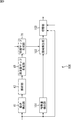
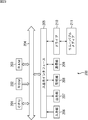
- FIG. 2 is a block diagram illustrating a configuration example of the CCU 12 of FIG.
- a motion detecting unit 41 includes a motion detecting unit 41, an analyzing unit 42, a frequency map generating unit 43, and a switching unit 44.
- the motion detection unit 41 of the CCU 12 receives an intraoperative image for each frame from the endoscope 19 in FIG.
- the motion detection unit 41 uses the intraoperative image and the intraoperative image held in the frame (time) before the intraoperative image for each detection unit (for example, one or more pixels) in the intraoperative image.
- a motion vector representing the amount and direction of movement of the living body is detected.
- a motion vector detection method there are a block matching method and a gradient method.
- the motion detection unit 41 supplies the motion vector of each detection unit of the intraoperative image to the analysis unit 42.
- the analysis unit 42 holds the motion vectors supplied from the motion detection unit 41 for analysis frames that are a plurality of frames (for example, 60 frames (one second)).
- the analysis unit 42 decomposes the motion vectors for the analysis frames that are held into horizontal and vertical motion vectors.
- the analysis unit 42 obtains, for each detection unit, a frequency having a larger maximum motion amount among the motion vectors in the horizontal direction and the vertical direction for the analysis frame.
- a method for obtaining the frequency of the motion vector for example, there is a method of performing FFT (Fast Fourier Transform) on the motion vector.
- FFT Fast Fourier Transform
- a frequency corresponding to the period of the time change is obtained.
- the analysis unit 42 supplies a frequency image representing the frequency of each pixel as a pixel value to the frequency map generation unit 43.
- the frequency map generation unit 43 Based on the frequency image supplied from the analysis unit 42, the frequency map generation unit 43 detects a region in the image that is composed of continuous detection units that are close in frequency, and an average value of the position and frequency in the image of the region. A frequency map representing the above is generated.
- the frequency map generation unit 43 smoothes the frequency image, performs region division for each frequency on the smoothed frequency image, and performs a specific biological part corresponding to each frequency.
- a region including for example, a specific organ, blood vessel, blood, etc.
- the detection unit for which the frequency could not be obtained is divided into frequency indefinite regions.
- the frequency map generation unit 43 generates a frequency map that represents each region in the frequency image with a color assigned to the frequency corresponding to the region, and supplies the frequency map to the switching unit 44.
- the switching unit 44 selects the intra-frame operation image transmitted from the endoscope 19 or the frequency map supplied from the frequency map generation unit 43 in accordance with the operation signal transmitted from the foot switch 26. .
- the switching unit 44 transmits the selected intraoperative image or frequency map to the display device 11 of FIG.
- FIG. 3 is a diagram for explaining the frequency of the horizontal motion vector obtained by the analysis unit 42.
- the horizontal axis represents time (frame), and the vertical axis represents the horizontal motion vector value.
- the motion vector value is a value that represents the direction of motion represented by the motion vector with positive and negative values, and represents the amount of motion with a value.
- the direction of motion represented by the motion vector is the right direction, for example, the motion vector value in the horizontal direction is a positive value, and when the direction is the left direction, the motion vector value is a negative value.
- the absolute value (amplitude) of the motion vector value in the horizontal direction during the time T corresponding to the number of analysis frames, that is, the maximum value of the motion amount is the absolute value A.
- the analysis unit 42 detects the frequency of the horizontal motion vector.
- the frequency corresponding to the period 1 / 2T is detected as the frequency of the horizontal motion vector.
- the frequency of the vertical motion vector can be obtained in the same manner as the frequency of the horizontal motion vector.
- FIG. 4 is a diagram illustrating an example of a frequency map.
- the frequency image after smoothing includes a detection unit representing 1 Hz, 40 Hz, or 2 Hz and a detection unit for which a frequency could not be obtained.
- the frequency map generation unit 43 uses the frequency images after smoothing as the regions 51 to 53 whose frequencies are 1 Hz, 40 Hz, and 2 Hz, respectively, and the frequency indefinite region that is a region where the frequency could not be obtained. It is divided into a total of 54 areas.
- the frequency map generator 43 assigns different colors to the areas 51 to 53 and the frequency indeterminate area 54, and generates the frequency maps 50 in which the colors of the areas 51 to 53 and the frequency indeterminate area 54 are different.
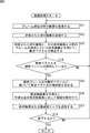
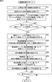
- FIG. 5 is a flowchart for explaining image processing of the CCU 12 of FIG.
- the motion detecting unit 41 and the switching unit 44 of the CCU 12 receive intra-frame intraoperative images from the endoscope 19 of FIG. 1.
- the motion detection unit 41 holds the received intraoperative image in units of frames.
- step S12 the switching unit 44 transmits the received intra-operative image in units of frames to the display device 11 in FIG.
- step S ⁇ b> 13 the motion detection unit 41 uses the intraoperative image in units of frames received in step S ⁇ b> 11 and the intraoperative image held in the frame prior to the intraoperative image, in each intraoperative image for each detection unit. A biological motion vector is detected.
- the motion detection unit 41 supplies the motion vector of each detection unit of the intraoperative image to the analysis unit 42.
- the analysis unit 42 holds the motion vector supplied from the motion detection unit 41.
- step S14 the analysis unit 42 determines whether or not the motion vector is retained for the analysis frame. If it is determined in step S14 that the motion vector is not yet held for the analysis frame, the process returns to step S11, and the processing of steps S11 to S14 is repeated until the analysis unit 42 holds the motion vector for the analysis frame. It is.
- step S15 the analysis unit 42 obtains the frequency of the motion vector for each detection unit based on the motion vector for the analysis frame that is held.
- the analysis unit 42 supplies a frequency image representing the obtained frequency of each pixel as a pixel value to the frequency map generation unit 43.
- step S16 the frequency map generation unit 43 smoothes the frequency image supplied from the analysis unit 42, and performs region division on the smoothed frequency image.
- the frequency map generation unit 43 generates a frequency map that represents each region in the divided peripheral image with a color assigned to a frequency corresponding to the region.
- the frequency map generation unit 43 supplies the frequency map to the switching unit 44.
- step S ⁇ b> 17 the switching unit 44 displays the intraoperative image received in the immediately preceding step S ⁇ b> 11 or the frequency map supplied from the frequency map generating unit 43 in accordance with the operation signal received from the foot switch 26. Transmit to device 11.
- step S18 the CCU 12 determines whether or not to end the image processing, for example, whether or not the user has operated the foot switch 26 to instruct the end of the image processing. If it is determined in step S18 that the image processing is not to be ended, the process returns to step S11, and steps S11 to S18 are performed until it is determined that the image processing is to be ended. At this time, in the process of step S13, the analysis unit 42 holds the motion vector supplied from the motion detection unit 41 in place of the oldest motion vector held. That is, the analysis unit 42 holds only the motion vector for the latest analysis frame.
- step S18 if it is determined in step S18 that the image processing is to end, the processing ends.
- the CCU 12 can detect a region including a specific living body part having a different frequency of the motion vector in the intraoperative image with high accuracy based on the frequency of the motion vector of the living body in the intraoperative image.
- the CCU 12 displays the frequency map and the intraoperative image by switching them, the operator or the like is linked with the region of the living body part that moves in synchronization with the heartbeat such as blood vessels and the heart in the intraoperative image, and breathing such as the lungs and the diaphragm. It is possible to easily distinguish the region of the living body part that moves. As a result, an improvement in the accuracy of surgery and a reduction in time can be expected.
- FIG. 6 is a block diagram illustrating a configuration example of the CCU according to the second embodiment of the endoscopic surgery system to which the present disclosure is applied.
- the CCU 70 causes the display device 11 to display, instead of the frequency map, a synchronization map that represents a region corresponding to a predetermined frequency among regions in the frequency map in a color different from other regions as an image processing result.
- the synchronization map generation unit 71 determines the frequency based on the frequency map supplied from the frequency map generation unit 43 and the frequency information indicating the frequency input from an external device (not shown). Of the regions in the map, a region including a specific living body part corresponding to the frequency represented by the frequency information is detected.
- the synchronization map generation unit 71 determines, for each region in the peripheral map, whether or not there is synchronization between the frequency corresponding to the region and the frequency represented by the frequency information. And the synchronous map production
- the frequency information includes, for example, heart rate information indicating a frequency determined based on a heart rate input from an electrocardiograph.
- the synchronization map generation unit 71 supplies the synchronization map to the switching unit 72.
- the switching unit 72 displays the intra-frame operation image received from the endoscope 19 or the synchronization map supplied from the synchronization map generating unit 71 in accordance with the operation signal transmitted from the foot switch 26 as shown in FIG. Transmit to device 11.
- FIG. 7 is a diagram illustrating an example of the synchronization map.
- the frequency map generating unit 43 generates the frequency map 50 of FIG.
- the frequency represented by the frequency information is 40 Hz.
- the synchronization map generation unit 71 deletes the regions 51 to 53 and the frequency indefinite region 54 of the frequency map 50 other than the region 52 corresponding to 40 Hz, and generates the synchronization map 80 of FIG.
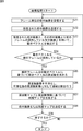
- FIG. 8 is a flowchart for explaining image processing of the CCU 70 of FIG.
- step S37 the synchronization map generator 71 generates a synchronization map based on the frequency map supplied from the frequency map generator 43 and the frequency information input from an external device (not shown).
- the synchronization map generation unit 71 supplies the synchronization map to the switching unit 72.
- step S ⁇ b> 38 the switching unit 72 responds to the operation signal received from the foot switch 26, the intra-frame intraoperative image received in the immediately preceding step S ⁇ b> 31, or the synchronization supplied from the synchronization map generating unit 71.
- the map is transmitted to the display device 11.
- step S39 is the same as the processing in step S18 in FIG.
- the operator or the like can easily locate a living body part moving at a predetermined frequency in the intraoperative image (for example, a blood vessel moving in synchronization with the heartbeat). Can be identified.
- ⁇ Third Embodiment> (Configuration example of CCU of the third embodiment of the endoscopic surgery system)
- the configuration of the third embodiment of the endoscopic surgery system to which the present disclosure is applied is the same as the configuration of the endoscopic surgery system 10 in FIG. 1 except for the configuration of the CCU. Accordingly, only the CCU will be described below.
- FIG. 9 is a block diagram illustrating a configuration example of the CCU according to the third embodiment of the endoscopic surgery system to which the present disclosure is applied.
- the CCU 100 detects a specific organ or blood vessel region based on the synchronization map and the feature amount of the intraoperative image.
- the feature amount detection unit 101 detects edge information and color information such as luminance, saturation, and hue from the intraoperative image received from the endoscope 19 as feature amounts, and sends them to the region detection unit 102. Supply.
- the region detection unit 102 detects a specific organ or blood vessel region based on the synchronization map generated by the synchronization map generation unit 71 and the feature amount supplied from the feature amount detection unit 101.
- the region detection unit 102 supplies the switching unit 103 with an organ map having the same size as the intraoperative image representing the detected specific organ or blood vessel region in a predetermined color.
- the switching unit 103 displays the intra-frame intraoperative image received from the endoscope 19 or the organ map supplied from the region detection unit 102 in accordance with the operation signal received from the foot switch 26 as shown in FIG. Transmit to device 11.
- FIG. 10 is a diagram illustrating a detection result of a blood vessel region based on a feature amount
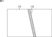
- FIG. 11 is a diagram illustrating an organ map.
- the synchronization map generator 71 generates the synchronization map 80 of FIG. 7 based on the heartbeat information. Further, the region detection unit 102 detects a blood vessel region.
- the region detection unit 102 first detects the tubule regions 111 to 113 in the intraoperative image 110 as blood vessel regions as shown in FIG. 10 based on the feature amount of the intraoperative image 110. That is, the region detection unit 102 cannot identify a blood vessel region only by the feature amount of the intraoperative image 110, and detects the capillary regions 111 to 113 including the blood vessel as the blood vessel region.
- the region detection unit 102 determines a region 112 that overlaps the region 52 included in the synchronization map 80 among the capillary regions 111 to 113 as a final blood vessel. Detected as a region. That is, the region detection unit 102 identifies a region 112 that moves in synchronization with the heartbeat among the capillary regions 111 to 113 as a blood vessel region. Then, the region detection unit 102 generates an organ map 115 having the same size as the intraoperative image representing the region 112 in a predetermined color.
- FIG. 12 is a flowchart for explaining the processing of the CCU 100 of FIG.
- step S ⁇ b> 58 the feature amount detection unit 101 detects the feature amount from the intraoperative image received from the endoscope 19 and supplies it to the region detection unit 102.
- step S59 the region detection unit 102 detects a specific organ or blood vessel region based on the feature amount supplied from the feature amount detection unit 101.
- step S ⁇ b> 53 the region detection unit 102 generates an organ map based on the detection result of step S ⁇ b> 52 and the synchronization map generated by the synchronization map generation unit 71, and supplies the organ map to the switching unit 103.
- step S ⁇ b> 61 the switching unit 103 responds to the operation signal received from the foot switch 26, and the intra-frame intraoperative image received in the immediately preceding step S ⁇ b> 51 or the organ map supplied from the region detection unit 102. Is transmitted to the display device 11.
- step S62 is the same as the processing in step S39 in FIG.
- the CCU 100 since the CCU 100 detects a specific organ or blood vessel region based on not only the feature amount of the intraoperative image but also the synchronization map, it can detect the specific organ or blood vessel region with high accuracy. it can. As a result, the surgeon or the like can identify a specific organ or blood vessel region in the intraoperative image with high accuracy using the organ map displayed on the display device 11.
- ⁇ Fourth embodiment> (Configuration example of CCU of the fourth embodiment of the endoscopic surgery system)
- the configuration of the fourth embodiment of the endoscopic surgery system to which the present disclosure is applied is the same as the configuration of the endoscopic surgery system 10 of FIG. 1 except for the configuration of the CCU. Accordingly, only the CCU will be described below.
- FIG. 13 is a block diagram illustrating a configuration example of the CCU according to the fourth embodiment of the endoscopic surgery system to which the present disclosure is applied.
- the configuration of the CCU 120 in FIG. 13 is that a synchronization map generation unit 121, a region detection unit 122, and a superimposition unit 124 are provided instead of the synchronization map generation unit 71, the region detection unit 102, and the switching unit 103, and a width detection unit.
- the point that 123 is newly provided is different from the configuration of the CCU 100 in FIG. 9.
- the CCU 120 detects the state of the blood vessel based on the width of the blood vessel region detected from the intraoperative image.
- the synchronization map generation unit 121 of the CCU 120 includes the frequency map in the frequency map based on the frequency map supplied from the frequency map generation unit 43 and heart rate information of a heartbeat input from an electrocardiograph (not shown). The region corresponding to the heartbeat in the region is detected, and a synchronization map is generated. The synchronization map generation unit 121 supplies the synchronization map to the region detection unit 122.
- the region detection unit 122 detects a blood vessel region based on the synchronization map generated by the synchronization map generation unit 121 and the feature amount supplied from the feature amount detection unit 101.
- the region detection unit 122 supplies a blood vessel map having the same size as the intraoperative image representing the detected blood vessel region in a predetermined color to the width detection unit 123.
- the width detection unit 123 detects the width of the blood vessel region in the blood vessel map supplied from the region detection unit 102 as a characteristic of the blood vessel region.
- the width detection unit 123 detects the hemostatic state of the blood vessel based on the temporal change in the width of the blood vessel region, and supplies the detection result to the superimposition unit 124.
- the superimposing unit 124 superimposes the state notification image representing the detection result supplied from the width detecting unit 123 on the intraoperative image received from the endoscope 19 in accordance with the operation signal received from the foot switch 26.
- the status notification image is, for example, an image of a message “successful hemostasis” when the detection result is a hemostatic state, and an image of a message “hemostatic failure” when the detection result is not the hemostatic state.
- the superimposing unit 124 transmits an intraoperative image on which the state notification image is superimposed or an intraoperative image on which the state notification image is not superimposed to the display device 11 according to the operation signal.
- FIG. 14 is a diagram illustrating an example of an intraoperative image before the blood vessel is clipped by the forceps 21
- FIG. 15 is a diagram illustrating an example of the intraoperative image after the blood vessel is clipped by the forceps 21.
- the width detection unit 123 determines the maximum width W1 of the region of the blood vessel 131. To detect.
- the blood pressure on the upstream side rises, and as shown in FIG.
- the width of the blood vessel 131 on the upstream side of the forceps 21 is larger than the width W1. Further, since the blood pressure downstream of the forceps 21 (right side in the example of FIG. 15) is lowered, the width of the blood vessel 131 on the downstream side of the forceps 21 is narrower than the width W1.
- the width detecting unit 123 detects that the state of the blood vessel 131 is a hemostatic state when the maximum width of the blood vessel 131 is increased.
- the width detection unit 123 detects that the state of the blood vessel 131 is not a hemostatic state.
- the clip is performed at the end of the region of the blood vessel 131, so that the blood vessel 131 downstream from the forceps 21 exists. do not do.
- the width of the blood vessel 131 upstream from the forceps 21 is larger than the width W1, so that the maximum width of the blood vessel 131 is thicker than W1.
- FIG. 16 is a flowchart for explaining the processing of the CCU 120 of FIG.
- step S77 the synchronization map generation unit 121 of the CCU 120 generates a synchronization map based on the frequency map supplied from the frequency map generation unit 43 and heart rate information of a heartbeat input from an electrocardiograph (not shown) or the like. To do.
- the synchronization map generation unit 121 supplies the synchronization map to the region detection unit 122.
- step S78 the feature amount detection unit 101 detects the feature amount from the intraoperative image received from the endoscope 19, and supplies the feature amount to the region detection unit 122.
- step S79 the region detection unit 122 detects a blood vessel region based on the feature amount supplied from the feature amount detection unit 101.
- step S ⁇ b> 80 the region detection unit 122 generates a blood vessel map based on the detection result of step S ⁇ b> 79 and the synchronization map supplied from the synchronization map generation unit 121, and supplies the blood vessel map to the width detection unit 123.
- step S81 the width detection unit 123 detects the width of the blood vessel region in the blood vessel map supplied from the region detection unit 102.
- step S82 the width detection unit 123 detects the hemostatic state of the blood vessel based on the temporal change in the width of the blood vessel region, and supplies the detection result to the superimposition unit 124.
- the superimposing unit 124 superimposes a state notification image representing the detection result supplied from the width detecting unit 123 on the intraoperative image received in the immediately preceding step S72. .
- step S83 the superimposing unit 124 transmits to the display device 11 the intraoperative image received from the endoscope 19 in the immediately preceding process of step S72 or the intraoperative image on which the state notification image is superimposed.
- step S84 is the same as the processing in step S62 in FIG.
- ⁇ Fifth embodiment> (Configuration example of CCU of fifth embodiment of endoscopic surgery system)
- the configuration of the fifth embodiment of the endoscopic surgery system to which the present disclosure is applied is the same as the configuration of the endoscopic surgery system 10 of FIG. 1 except for the configuration of the CCU. Accordingly, only the CCU will be described below.
- FIG. 17 is a block diagram illustrating a configuration example of the CCU according to the fifth embodiment of the endoscopic surgery system to which the present disclosure is applied.
- the CCU 140 determines an arterial region and a venous region among blood vessel regions based on the motion vector and the feature amount of the intraoperative image.
- the determination unit 141 of the CCU 140 is generated by the region detection unit 122 based on the motion vector detected by the motion detection unit 41 and the feature amount of the intraoperative image detected by the feature amount detection unit 101. It is determined whether the blood vessel region in the blood vessel map is an arterial region or a vein region.
- arterial blood has higher luminance and saturation than venous blood, and the hue is closer to the plus side (spectral characteristics are on the longer wavelength side).
- the hue is closer to the plus side (spectral characteristics are on the longer wavelength side).
- adjacent blood vessels are often a pair of an artery and a vein, the direction of blood flow is often reversed.
- arteries have a larger pulsation than veins.
- the determination unit 141 performs principal component analysis or the like based on the color information of the motion vector and the feature amount of the blood vessel region in the blood vessel map, so that the region is an arterial region, or It is determined whether the region is a vein. That is, the determination unit 141 determines the type of blood vessel included in the blood vessel region.
- the discriminating unit 141 generates an arteriovenous map based on the discrimination result of each region, and changes the color of the vein region and the artery region in the blood vessel map, and supplies the generated arteriovenous map to the switching unit 142.
- the switching unit 142 transmits the intraoperative image received from the endoscope 19 or the arteriovenous map supplied from the determination unit 141 to the display device 11 according to the operation signal received from the foot switch 26.
- FIG. 18 is a diagram illustrating an example of an arteriovenous map.
- the determination unit 141 has a large amount of motion, luminance, and saturation, and a positive hue among pairs of adjacent blood vessel regions in which the average value of the motion vector values in the horizontal direction or the vertical direction is opposite.
- the one approaching the side is determined as an arterial region, and the other is determined as a vein region.
- the colors of the adjacent blood vessel region 151 and region 152 in the arteriovenous map 150 are different.
- the color of the area 151 in the arteriovenous map 150 is a color that represents the vein area
- the color of the area 152 is a color that represents the arterial area.
- FIG. 19 is a flowchart for explaining image processing of the CCU 140 of FIG.
- step S111 the determination unit 141 of the CCU 140 determines whether the blood vessel region in the blood vessel map is an arterial region or a vein region based on the motion vector and the feature amount of the intraoperative image. Generate an arteriovenous map.
- the determination unit 141 supplies the arteriovenous map to the switching unit 142.
- step S ⁇ b> 112 the switching unit 142 displays the intraoperative image received from the endoscope 19 or the arteriovenous map supplied from the determination unit 141 in accordance with the operation signal received from the foot switch 26. Send to.
- step S113 is the same as the processing in step S84 in FIG.
- the CCU 140 discriminates the arterial region and the venous region in the vascular region based on the feature amount and the motion vector of the intraoperative image. Therefore, the arterial region and the vein region can be distinguished with high accuracy.
- the color information changes depending on the illumination state and the depth of the blood vessel when the intraoperative image is taken. It is difficult to discriminate these areas with high accuracy.
- the arterial region and the venous region are determined based on both the feature quantity and the motion vector of the intraoperative image. However, the determination is performed based on one of the two. Also good.
- ⁇ Sixth embodiment> (Configuration example of CCU of the sixth embodiment of the endoscopic surgery system)
- the configuration of the sixth embodiment of the endoscopic surgery system to which the present disclosure is applied is the same as the configuration of the endoscopic surgery system 10 of FIG. 1 except for the configuration of the CCU. Accordingly, only the CCU will be described below.
- FIG. 20 is a block diagram illustrating a configuration example of the CCU of the sixth embodiment of the endoscopic surgery system to which the present disclosure is applied.
- the configuration of the CCU 160 in FIG. 20 is different from the configuration of the CCU 140 in FIG. 17 in that an area detection unit 161, an intersection detection unit 162, and a superimposition unit 163 are provided instead of the region detection unit 122, the determination unit 141, and the switching unit 142. Different.
- the CCU 160 detects a bleeding region based on the synchronization map and the feature amount, and detects a bleeding point based on the motion vector of the bleeding region.
- the region detection unit 161 of the CCU 160 detects a bleeding region based on the synchronization map generated by the synchronization map generation unit 121 and the feature amount supplied from the feature amount detection unit 101.
- the region detection unit 161 is, for example, a region having a size equal to or larger than a predetermined size having red color information as a feature amount, and is synchronized with the heartbeat in the synchronization map.
- the area is detected as a bleeding area.
- the region detection unit 122 supplies the intersection detection unit 162 with a bleeding map having the same size as the intraoperative image representing the detected bleeding region in a predetermined color.
- the intersection detection unit 162 determines the intersection of lines obtained by extending the start point of the bleeding motion vector in the bleeding region of the bleeding map supplied from the region detection unit 161 among the motion vectors supplied from the motion detection unit 41. Detect as.
- the intersection detection unit 162 supplies bleeding point information indicating the position of the bleeding point in the intraoperative image to the superimposing unit 163.
- the superimposing unit 163 is located at the position of the bleeding point represented by the bleeding point information supplied from the intersection detection unit 162 in the intraoperative image received from the endoscope 19. A bleeding point image representing a bleeding point is superimposed.
- the intersection detection unit 162 transmits the intraoperative image received from the endoscope 19 or the intraoperative image on which the bleeding point image is superimposed to the display device 11 of FIG.
- FIG. 21 is a diagram for explaining detection of a bleeding point by the intersection detection unit 162 in FIG.
- each motion vector 172 in the bleeding region 171 in the bleeding map 170 is distributed radially from the bleeding point. Accordingly, as shown in FIG. 21, the intersection detection unit 162 extends the start point 172A of each motion vector 172 in the direction opposite to the direction of the motion vector 172, and sets the intersection 173 of the extended motion vector 172 as a bleeding point. Detect as.
- FIG. 22 is a flowchart illustrating image processing of the CCU 160 in FIG.
- step S129 the region detection unit 161 of the CCU 160 detects a red region having a size equal to or larger than a predetermined size as a bleeding region based on the color information in the feature amount supplied from the feature amount detection unit 101.
- step S130 the region detection unit 161 generates a bleeding map based on the detection result obtained by the process in step S129 and the synchronization map generated by the synchronization map generation unit 121. Specifically, the region detection unit 161 detects a bleeding region detected by the process of step S129 out of the regions in the synchronization map as a final bleeding region. Then, the area detection unit 161 generates a bleeding map based on the detected bleeding area and supplies the bleeding map to the intersection detection unit 162.
- step S131 the intersection detection unit 162 calculates an intersection of lines obtained by extending the start point of the motion vector in the bleeding region in the bleeding map supplied from the region detection unit 161 among the motion vectors supplied from the motion detection unit 41. Detect as a bleeding point.
- the intersection detection unit 162 supplies the bleeding point information to the superimposition unit 163.
- the superimposing unit 163 is located at the position of the bleeding point represented by the bleeding point information supplied from the intersection detection unit 162 in the intraoperative image received from the endoscope 19. Superimpose the bleeding point image.
- step S132 the intersection detection unit 162 displays the intraoperative image received from the endoscope 19 or the intraoperative image on which the bleeding point image is superimposed in accordance with the operation signal received from the foot switch 26 in FIG. It transmits to the display device 11.
- step S133 is the same as the processing in step S113 in FIG.
- the CCU 160 detects the bleeding point based on the motion vector of the intraoperative image. Accordingly, the CCU 160 can display the bleeding point image on the display device 11 by superimposing the bleeding point image on the intraoperative image. As a result, the operator can easily recognize the position of the bleeding point.
- ⁇ Seventh embodiment> (Description of computer to which the present disclosure is applied)
- the series of processes described above can be executed by hardware or can be executed by software.
- a program constituting the software is installed in the computer.
- the computer includes, for example, a general-purpose personal computer capable of executing various functions by installing various programs by installing a computer incorporated in dedicated hardware.
- FIG. 23 is a block diagram showing an example of the hardware configuration of a computer that executes the above-described series of processing by a program.
- a CPU Central Processing Unit
- ROM Read Only Memory
- RAM Random Access Memory
- An input / output interface 205 is further connected to the bus 204.
- An input unit 206, an output unit 207, a storage unit 208, a communication unit 209, and a drive 210 are connected to the input / output interface 205.
- the input unit 206 includes a keyboard, a mouse, a microphone, and the like.
- the output unit 207 includes a display, a speaker, and the like.
- the storage unit 208 includes a hard disk, a nonvolatile memory, and the like.
- the communication unit 209 includes a network interface and the like.
- the drive 210 drives a removable medium 211 such as a magnetic disk, an optical disk, a magneto-optical disk, or a semiconductor memory.
- the CPU 201 loads the program stored in the storage unit 208 to the RAM 203 via the input / output interface 205 and the bus 204 and executes the program. A series of processing is performed.
- the intermediate result of the process and information used for the process are stored in the ROM 202, the RAM 203, or the like.
- the program executed by the computer 200 can be provided by being recorded in, for example, a removable medium 211 such as a package medium.
- the program can be provided via a wired or wireless transmission medium such as a local area network, the Internet, or digital satellite broadcasting.
- the program can be installed in the storage unit 208 via the input / output interface 205 by attaching the removable medium 211 to the drive 210.
- the program can be received by the communication unit 209 via a wired or wireless transmission medium and installed in the storage unit 208.
- the program can be installed in the ROM 202 or the storage unit 208 in advance.
- the program executed by the computer 200 may be a program that is processed in time series in the order described in this specification, or a necessary timing such as in parallel or when a call is made. It may be a program in which processing is performed.
- the system means a set of a plurality of components (devices, modules (parts), etc.), and it does not matter whether all the components are in the same housing. Accordingly, a plurality of devices housed in separate housings and connected via a network and a single device housing a plurality of modules in one housing are all systems. .
- the frequency map, the synchronization map, the organ map, and the arteriovenous map may be displayed superimposed on the intraoperative image or displayed in parallel on the same screen as the intraoperative image.
- the detection of the blood vessel region in the fourth and fifth embodiments and the detection of the bleeding region in the sixth embodiment may be performed based only on the feature amount of the intraoperative image, or may be synchronized. You may make it carry out based only on a map.
- the hemostatic state of the arterial blood vessel or the venous blood vessel determined in the fifth embodiment may be determined. Further, by combining at least two of the first to sixth embodiments, it is possible to generate at least two of a frequency map, a synchronization map, an organ map, a state notification image, an arteriovenous map, and a bleeding point image. Also good.
- the present technology can be applied to a surgical system other than an endoscopic surgical system as long as it is a surgical system that captures an image during an operation and processes the image.
- the present technology can also be applied to a surgical system that takes an intraoperative image with a video microscope and processes the image.
- this indication can also take the following structures.
- a motion detector that detects a motion vector of a living body in the intraoperative image using intraoperative images at different times; and An analysis unit for obtaining a frequency of the motion vector detected by the motion detection unit;
- An image processing apparatus comprising: a region detecting unit that detects a region including a specific living body part in the intraoperative image based on the frequency obtained by the analyzing unit.
- the region detection unit is configured to detect, for each frequency, the region including the specific biological part corresponding to the frequency.
- the region detection unit is configured to detect the region including the specific living body part corresponding to a predetermined frequency.
- the predetermined frequency is determined based on heartbeat information.
- the image processing apparatus is configured to detect the region based on the frequency and a feature amount of the intraoperative image.
- the region includes a specific organ or blood vessel.
- the image processing apparatus according to any one of (1) to (6), further including: a state detection unit that detects a state of the region based on the feature of the region detected by the region detection unit.
- the region is a region including a blood vessel, The image processing apparatus according to (7), wherein the state detection unit is configured to detect a hemostatic state of the blood vessel based on a width of the blood vessel.
- the image processing apparatus further including: a superimposing unit that superimposes the state notification image generated based on the state of the region on the intraoperative image.
- the image processing apparatus further includes a determination unit that determines the type of the specific living body part included in the region detected by the region detection unit. ).
- the determination unit is configured to determine the type of the specific living body part based on the motion vector detected by the motion detection unit and the feature amount of the intraoperative image.
- the region is a region including a blood vessel, The image processing apparatus according to (10) or (11), wherein the determination unit is configured to determine whether the blood vessel is an artery or a vein.
- the image processing apparatus according to any one of (1) to (12), further including: an intersection detection unit that detects an intersection of the motion vectors of the specific living body part in the region detected by the region detection unit.
- the region detection unit detects a region including bleeding based on the frequency and the feature amount of the intraoperative image,
- the image processing device according to (13), wherein the intersection detection unit is configured to detect a bleeding point based on an intersection of the motion vectors of bleeding in the region.
- the image processing device A motion detection step of detecting a motion vector of a living body in the intraoperative image using intraoperative images at different times; and An analysis step for obtaining a frequency of the motion vector detected by the processing of the motion detection step; An area detection step of detecting an area including a specific living body part in the intraoperative image based on the frequency obtained by the process of the analysis step.
- the surgical operation system according to (16) wherein the imaging device that captures the intraoperative image is configured to be an endoscope.
- the imaging device that captures the intraoperative image is configured to be a video microscope.
Landscapes
- Health & Medical Sciences (AREA)
- Life Sciences & Earth Sciences (AREA)
- Surgery (AREA)
- Engineering & Computer Science (AREA)
- Medical Informatics (AREA)
- Biomedical Technology (AREA)
- Heart & Thoracic Surgery (AREA)
- Molecular Biology (AREA)
- Animal Behavior & Ethology (AREA)
- General Health & Medical Sciences (AREA)
- Public Health (AREA)
- Veterinary Medicine (AREA)
- Pathology (AREA)
- Physics & Mathematics (AREA)
- Nuclear Medicine, Radiotherapy & Molecular Imaging (AREA)
- Biophysics (AREA)
- Physiology (AREA)
- Radiology & Medical Imaging (AREA)
- Cardiology (AREA)
- Oral & Maxillofacial Surgery (AREA)
- Computer Vision & Pattern Recognition (AREA)
- Signal Processing (AREA)
- Optics & Photonics (AREA)
- Vascular Medicine (AREA)
- Artificial Intelligence (AREA)
- Psychiatry (AREA)
- Multimedia (AREA)
- Theoretical Computer Science (AREA)
- Gynecology & Obstetrics (AREA)
- General Physics & Mathematics (AREA)
- Dentistry (AREA)
- Plasma & Fusion (AREA)
- Otolaryngology (AREA)
- Endoscopes (AREA)
- Image Analysis (AREA)
Abstract
Priority Applications (3)
| Application Number | Priority Date | Filing Date | Title |
|---|---|---|---|
| US15/568,887 US10729307B2 (en) | 2015-06-05 | 2016-05-25 | Image processing device, image processing method, and surgical system |
| EP16803153.2A EP3305171B1 (fr) | 2015-06-05 | 2016-05-25 | Appareil de traitement d'image, procédé de traitement d'image et système chirurgical |
| JP2017521849A JPWO2016194718A1 (ja) | 2015-06-05 | 2016-05-25 | 画像処理装置、画像処理方法、および手術システム |
Applications Claiming Priority (2)
| Application Number | Priority Date | Filing Date | Title |
|---|---|---|---|
| JP2015-114912 | 2015-06-05 | ||
| JP2015114912 | 2015-06-05 |
Publications (1)
| Publication Number | Publication Date |
|---|---|
| WO2016194718A1 true WO2016194718A1 (fr) | 2016-12-08 |
Family
ID=57442372
Family Applications (1)
| Application Number | Title | Priority Date | Filing Date |
|---|---|---|---|
| PCT/JP2016/065387 Ceased WO2016194718A1 (fr) | 2015-06-05 | 2016-05-25 | Appareil de traitement d'image, procédé de traitement d'image et système chirurgical |
Country Status (4)
| Country | Link |
|---|---|
| US (1) | US10729307B2 (fr) |
| EP (1) | EP3305171B1 (fr) |
| JP (1) | JPWO2016194718A1 (fr) |
| WO (1) | WO2016194718A1 (fr) |
Cited By (4)
| Publication number | Priority date | Publication date | Assignee | Title |
|---|---|---|---|---|
| WO2019102750A1 (fr) * | 2017-11-24 | 2019-05-31 | ソニー株式会社 | Dispositif, procédé et programme de traitement d'images |
| CN110381815A (zh) * | 2017-03-22 | 2019-10-25 | 威里利生命科学有限责任公司 | 血管的检测 |
| WO2020262262A1 (fr) * | 2019-06-27 | 2020-12-30 | ソニー株式会社 | Système d'observation médicale, dispositif de commande et procédé de commande |
| WO2025022718A1 (fr) * | 2023-07-21 | 2025-01-30 | 富士フイルム株式会社 | Dispositif d'assistance médicale, dispositif d'endoscope, procédé d'assistance médicale et programme |
Families Citing this family (3)
| Publication number | Priority date | Publication date | Assignee | Title |
|---|---|---|---|---|
| EP3697294B1 (fr) * | 2017-10-16 | 2023-12-06 | Massachusetts Institute Of Technology | Système et procédé de mesures hématologiques non invasives |
| US12211186B2 (en) * | 2019-04-17 | 2025-01-28 | Nikon Corporation | Video processing apparatus, video processing method, and recording medium |
| EP4529839A3 (fr) | 2019-07-24 | 2025-04-16 | Massachusetts Institute of Technology | Inserts de doigt pour dispositif d'imagerie de pliage d'ongles |
Citations (2)
| Publication number | Priority date | Publication date | Assignee | Title |
|---|---|---|---|---|
| JP2011024628A (ja) * | 2009-07-21 | 2011-02-10 | Olympus Corp | 画像処理装置、画像処理プログラムおよび画像処理方法 |
| JP2014003990A (ja) * | 2012-06-21 | 2014-01-16 | Olympus Medical Systems Corp | 内視鏡装置および内視鏡観察システム |
Family Cites Families (12)
| Publication number | Priority date | Publication date | Assignee | Title |
|---|---|---|---|---|
| US20100081875A1 (en) * | 2003-07-15 | 2010-04-01 | EndoRobotics Inc. | Surgical Device For Minimal Access Surgery |
| JP4493637B2 (ja) | 2006-09-29 | 2010-06-30 | オリンパス株式会社 | 診断支援装置及び診断支援方法 |
| US20080243162A1 (en) * | 2007-04-02 | 2008-10-02 | Norikiyo Shibata | Trocar |
| JP5038027B2 (ja) * | 2007-06-13 | 2012-10-03 | オリンパス株式会社 | 画像処理装置およびこれを備えた内視鏡装置 |
| JP4789964B2 (ja) * | 2008-04-01 | 2011-10-12 | オリンパス株式会社 | 画像処理装置、画像処理プログラム、画像処理方法、および電子機器 |
| KR102163327B1 (ko) * | 2012-07-25 | 2020-10-08 | 인튜어티브 서지컬 오퍼레이션즈 인코포레이티드 | 수술 시스템의 효율적인 쌍방향 출혈 검출 방법 및 시스템 |
| JP6102166B2 (ja) * | 2012-10-10 | 2017-03-29 | 株式会社ニコン | 心筋細胞の運動検出方法、心筋細胞の培養方法、薬剤評価方法、画像処理プログラム及び画像処理装置 |
| WO2014092650A1 (fr) * | 2012-12-11 | 2014-06-19 | Agency For Science, Technology And Research | Endoscopes |
| JP6494903B2 (ja) * | 2013-02-14 | 2019-04-03 | ソニー株式会社 | 分析システム、分析プログラム及び分析方法 |
| WO2014165805A2 (fr) * | 2013-04-04 | 2014-10-09 | Children's National Medical Center | Dispositif et procédé permettant de générer des images composites pour une chirurgie endoscopique d'une anatomie mobile et déformable |
| JP6265627B2 (ja) * | 2013-05-23 | 2018-01-24 | オリンパス株式会社 | 内視鏡装置及び内視鏡装置の作動方法 |
| EP3202315A4 (fr) * | 2015-04-21 | 2018-06-20 | Olympus Corporation | Dispositif médical et procédé de fonctionnement d'un dispositif médical |
-
2016
- 2016-05-25 WO PCT/JP2016/065387 patent/WO2016194718A1/fr not_active Ceased
- 2016-05-25 JP JP2017521849A patent/JPWO2016194718A1/ja active Pending
- 2016-05-25 EP EP16803153.2A patent/EP3305171B1/fr not_active Not-in-force
- 2016-05-25 US US15/568,887 patent/US10729307B2/en active Active
Patent Citations (2)
| Publication number | Priority date | Publication date | Assignee | Title |
|---|---|---|---|---|
| JP2011024628A (ja) * | 2009-07-21 | 2011-02-10 | Olympus Corp | 画像処理装置、画像処理プログラムおよび画像処理方法 |
| JP2014003990A (ja) * | 2012-06-21 | 2014-01-16 | Olympus Medical Systems Corp | 内視鏡装置および内視鏡観察システム |
Non-Patent Citations (1)
| Title |
|---|
| See also references of EP3305171A4 * |
Cited By (6)
| Publication number | Priority date | Publication date | Assignee | Title |
|---|---|---|---|---|
| CN110381815A (zh) * | 2017-03-22 | 2019-10-25 | 威里利生命科学有限责任公司 | 血管的检测 |
| JP2020514882A (ja) * | 2017-03-22 | 2020-05-21 | ヴェリリー ライフ サイエンシズ エルエルシー | 血管の検出 |
| JP7134985B2 (ja) | 2017-03-22 | 2022-09-12 | ヴェリリー ライフ サイエンシズ エルエルシー | 血管の検出 |
| WO2019102750A1 (fr) * | 2017-11-24 | 2019-05-31 | ソニー株式会社 | Dispositif, procédé et programme de traitement d'images |
| WO2020262262A1 (fr) * | 2019-06-27 | 2020-12-30 | ソニー株式会社 | Système d'observation médicale, dispositif de commande et procédé de commande |
| WO2025022718A1 (fr) * | 2023-07-21 | 2025-01-30 | 富士フイルム株式会社 | Dispositif d'assistance médicale, dispositif d'endoscope, procédé d'assistance médicale et programme |
Also Published As
| Publication number | Publication date |
|---|---|
| US20180098683A1 (en) | 2018-04-12 |
| US10729307B2 (en) | 2020-08-04 |
| EP3305171B1 (fr) | 2021-09-15 |
| EP3305171A4 (fr) | 2019-01-16 |
| JPWO2016194718A1 (ja) | 2018-03-29 |
| EP3305171A1 (fr) | 2018-04-11 |
Similar Documents
| Publication | Publication Date | Title |
|---|---|---|
| WO2016194718A1 (fr) | Appareil de traitement d'image, procédé de traitement d'image et système chirurgical | |
| US10600183B2 (en) | Detection of blood vessels | |
| CN109310279B (zh) | 信息处理设备、信息处理方法、程序和医疗观察系统 | |
| US11004197B2 (en) | Medical image processing apparatus, medical image processing method, and program | |
| CN110651333B (zh) | 手术成像系统、方法和计算机程序产品 | |
| US10904437B2 (en) | Control apparatus and control method | |
| US20240257509A1 (en) | Information Processing Device, Information Processing Method, and Recording Medium | |
| WO2019181432A1 (fr) | Système d'assistance opératoire, dispositif de traitement d'informations et programme | |
| US10413369B2 (en) | Device, method, and system for image guided surgical resection | |
| JP7127538B2 (ja) | 画像処理装置、医療機器の作動方法及び医療システム | |
| WO2015020093A1 (fr) | Appareil d'observation d'images chirurgicales | |
| JP2017176318A (ja) | 医療用立体観察装置、医療用立体観察方法、プログラム、及び医療用立体観察システム | |
| WO2020008920A1 (fr) | Système d'observation médicale, dispositif d'observation médicale, et procédé d'entraînement de dispositif d'observation médicale | |
| JPWO2018193799A1 (ja) | 情報処理装置、および情報処理方法、並びにプログラム | |
| US20210369080A1 (en) | Medical observation system, medical signal processing device, and medical signal processing device driving method | |
| US20190183322A1 (en) | Medical image processing device, image processing method, and program | |
| WO2021095697A1 (fr) | Appareil de traitement d'informations, procédé et programme de génération | |
| US12266127B2 (en) | Medical system, signal processing device, and signal processing method | |
| US12290233B2 (en) | Information processing device and generation method | |
| US20210228061A1 (en) | Medical observation system, medical observation apparatus, and drive method of medical observation apparatus | |
| CN118735870A (zh) | 基于机器视觉的动脉区域检测方法、装置、设备、介质以及系统 |
Legal Events
| Date | Code | Title | Description |
|---|---|---|---|
| 121 | Ep: the epo has been informed by wipo that ep was designated in this application |
Ref document number: 16803153 Country of ref document: EP Kind code of ref document: A1 |
|
| WWE | Wipo information: entry into national phase |
Ref document number: 15568887 Country of ref document: US |
|
| ENP | Entry into the national phase |
Ref document number: 2017521849 Country of ref document: JP Kind code of ref document: A |
|
| NENP | Non-entry into the national phase |
Ref country code: DE |
|
| WWE | Wipo information: entry into national phase |
Ref document number: 2016803153 Country of ref document: EP |