WO2016194832A1 - Élément de membrane de séparation de gaz acide de type spirale, module de membrane de séparation de gaz acide de type spirale, et dispositif de séparation de gaz acide - Google Patents
Élément de membrane de séparation de gaz acide de type spirale, module de membrane de séparation de gaz acide de type spirale, et dispositif de séparation de gaz acide Download PDFInfo
- Publication number
- WO2016194832A1 WO2016194832A1 PCT/JP2016/065775 JP2016065775W WO2016194832A1 WO 2016194832 A1 WO2016194832 A1 WO 2016194832A1 JP 2016065775 W JP2016065775 W JP 2016065775W WO 2016194832 A1 WO2016194832 A1 WO 2016194832A1
- Authority
- WO
- WIPO (PCT)
- Prior art keywords
- separation membrane
- spiral
- gas separation
- gas
- acidic gas
- Prior art date
- Legal status (The legal status is an assumption and is not a legal conclusion. Google has not performed a legal analysis and makes no representation as to the accuracy of the status listed.)
- Ceased
Links
Images


Classifications
-
- B—PERFORMING OPERATIONS; TRANSPORTING
- B01—PHYSICAL OR CHEMICAL PROCESSES OR APPARATUS IN GENERAL
- B01D—SEPARATION
- B01D63/00—Apparatus in general for separation processes using semi-permeable membranes
- B01D63/10—Spiral-wound membrane modules
- B01D63/107—Specific properties of the central tube or the permeate channel
-
- B—PERFORMING OPERATIONS; TRANSPORTING
- B01—PHYSICAL OR CHEMICAL PROCESSES OR APPARATUS IN GENERAL
- B01D—SEPARATION
- B01D53/00—Separation of gases or vapours; Recovering vapours of volatile solvents from gases; Chemical or biological purification of waste gases, e.g. engine exhaust gases, smoke, fumes, flue gases, aerosols
- B01D53/22—Separation of gases or vapours; Recovering vapours of volatile solvents from gases; Chemical or biological purification of waste gases, e.g. engine exhaust gases, smoke, fumes, flue gases, aerosols by diffusion
- B01D53/228—Separation of gases or vapours; Recovering vapours of volatile solvents from gases; Chemical or biological purification of waste gases, e.g. engine exhaust gases, smoke, fumes, flue gases, aerosols by diffusion characterised by specific membranes
-
- B—PERFORMING OPERATIONS; TRANSPORTING
- B01—PHYSICAL OR CHEMICAL PROCESSES OR APPARATUS IN GENERAL
- B01D—SEPARATION
- B01D53/00—Separation of gases or vapours; Recovering vapours of volatile solvents from gases; Chemical or biological purification of waste gases, e.g. engine exhaust gases, smoke, fumes, flue gases, aerosols
- B01D53/34—Chemical or biological purification of waste gases
- B01D53/46—Removing components of defined structure
- B01D53/62—Carbon oxides
-
- B—PERFORMING OPERATIONS; TRANSPORTING
- B01—PHYSICAL OR CHEMICAL PROCESSES OR APPARATUS IN GENERAL
- B01D—SEPARATION
- B01D69/00—Semi-permeable membranes for separation processes or apparatus characterised by their form, structure or properties; Manufacturing processes specially adapted therefor
- B01D69/10—Supported membranes; Membrane supports
- B01D69/106—Membranes in the pores of a support, e.g. polymerized in the pores or voids
-
- B—PERFORMING OPERATIONS; TRANSPORTING
- B01—PHYSICAL OR CHEMICAL PROCESSES OR APPARATUS IN GENERAL
- B01D—SEPARATION
- B01D69/00—Semi-permeable membranes for separation processes or apparatus characterised by their form, structure or properties; Manufacturing processes specially adapted therefor
- B01D69/10—Supported membranes; Membrane supports
- B01D69/107—Organic support material
- B01D69/1071—Woven, non-woven or net mesh
-
- B—PERFORMING OPERATIONS; TRANSPORTING
- B01—PHYSICAL OR CHEMICAL PROCESSES OR APPARATUS IN GENERAL
- B01D—SEPARATION
- B01D69/00—Semi-permeable membranes for separation processes or apparatus characterised by their form, structure or properties; Manufacturing processes specially adapted therefor
- B01D69/10—Supported membranes; Membrane supports
- B01D69/108—Inorganic support material
-
- B—PERFORMING OPERATIONS; TRANSPORTING
- B01—PHYSICAL OR CHEMICAL PROCESSES OR APPARATUS IN GENERAL
- B01D—SEPARATION
- B01D69/00—Semi-permeable membranes for separation processes or apparatus characterised by their form, structure or properties; Manufacturing processes specially adapted therefor
- B01D69/12—Composite membranes; Ultra-thin membranes
- B01D69/1213—Laminated layers
-
- B—PERFORMING OPERATIONS; TRANSPORTING
- B01—PHYSICAL OR CHEMICAL PROCESSES OR APPARATUS IN GENERAL
- B01D—SEPARATION
- B01D69/00—Semi-permeable membranes for separation processes or apparatus characterised by their form, structure or properties; Manufacturing processes specially adapted therefor
- B01D69/12—Composite membranes; Ultra-thin membranes
- B01D69/1216—Three or more layers
-
- B—PERFORMING OPERATIONS; TRANSPORTING
- B01—PHYSICAL OR CHEMICAL PROCESSES OR APPARATUS IN GENERAL
- B01D—SEPARATION
- B01D69/00—Semi-permeable membranes for separation processes or apparatus characterised by their form, structure or properties; Manufacturing processes specially adapted therefor
- B01D69/12—Composite membranes; Ultra-thin membranes
- B01D69/1218—Layers having the same chemical composition, but different properties, e.g. pore size, molecular weight or porosity
-
- B—PERFORMING OPERATIONS; TRANSPORTING
- B01—PHYSICAL OR CHEMICAL PROCESSES OR APPARATUS IN GENERAL
- B01D—SEPARATION
- B01D69/00—Semi-permeable membranes for separation processes or apparatus characterised by their form, structure or properties; Manufacturing processes specially adapted therefor
- B01D69/14—Dynamic membranes
- B01D69/141—Heterogeneous membranes, e.g. containing dispersed material; Mixed matrix membranes
- B01D69/142—Heterogeneous membranes, e.g. containing dispersed material; Mixed matrix membranes with "carriers"
-
- B—PERFORMING OPERATIONS; TRANSPORTING
- B01—PHYSICAL OR CHEMICAL PROCESSES OR APPARATUS IN GENERAL
- B01D—SEPARATION
- B01D2325/00—Details relating to properties of membranes
- B01D2325/08—Patterned membranes
-
- B—PERFORMING OPERATIONS; TRANSPORTING
- B01—PHYSICAL OR CHEMICAL PROCESSES OR APPARATUS IN GENERAL
- B01D—SEPARATION
- B01D53/00—Separation of gases or vapours; Recovering vapours of volatile solvents from gases; Chemical or biological purification of waste gases, e.g. engine exhaust gases, smoke, fumes, flue gases, aerosols
- B01D53/22—Separation of gases or vapours; Recovering vapours of volatile solvents from gases; Chemical or biological purification of waste gases, e.g. engine exhaust gases, smoke, fumes, flue gases, aerosols by diffusion
-
- B—PERFORMING OPERATIONS; TRANSPORTING
- B01—PHYSICAL OR CHEMICAL PROCESSES OR APPARATUS IN GENERAL
- B01D—SEPARATION
- B01D63/00—Apparatus in general for separation processes using semi-permeable membranes
-
- B—PERFORMING OPERATIONS; TRANSPORTING
- B01—PHYSICAL OR CHEMICAL PROCESSES OR APPARATUS IN GENERAL
- B01D—SEPARATION
- B01D63/00—Apparatus in general for separation processes using semi-permeable membranes
- B01D63/10—Spiral-wound membrane modules
- B01D63/12—Spiral-wound membrane modules comprising multiple spiral-wound assemblies
-
- B—PERFORMING OPERATIONS; TRANSPORTING
- B01—PHYSICAL OR CHEMICAL PROCESSES OR APPARATUS IN GENERAL
- B01D—SEPARATION
- B01D69/00—Semi-permeable membranes for separation processes or apparatus characterised by their form, structure or properties; Manufacturing processes specially adapted therefor
Definitions
- the present invention relates to a spiral acidic gas separation membrane element, an acidic gas separation membrane module, and an acidic gas separation device that separates the acidic gas from a mixed gas containing at least an acidic gas.
- an acid gas separation membrane element using a gas separation membrane for example, a winding in which a separation membrane, a supply-side channel material, and a permeation-side channel material are wound in a laminated state around a central tube having a plurality of holes.
- the flow direction of the mixed gas and the flow direction of the permeated gas that has permeated through the separation membrane are substantially cross-shaped, so that the permeated gas can be immediately collected in the central tube.
- the holes are uniformly distributed on the surface of the central tube.
- the central tube is swept to maintain the partial pressure difference between the acidic gas contained in the mixed gas and the permeated gas that has permeated through the separation membrane to improve the separation efficiency in the separation membrane.
- a fluid supply port and a discharge port are formed.
- a separation membrane that uses a facilitated transport mechanism for selective permeation of acid gas changes the permeation amount of acid gas depending on humidity, and the higher the humidity, the greater the permeation amount of acid gas.
- water vapor contained in the permeated gas that has passed through the separation membrane is immediately collected together with the acid gas in the central tube. There is a problem that the separation efficiency of the acidic gas in the separation membrane is lowered.
- a supply source for supplying water vapor having high thermal energy is prepared, and the pressure, temperature, and flow rate of the water vapor are prepared. It is difficult to realize energy saving in the gas membrane separation process.
- the present invention has been made in consideration of the above-mentioned problems, and its main purpose is to separate the acidic gas from a mixed gas containing at least the acidic gas and water vapor more efficiently than before, and to save energy.
- An object of the present invention is to provide a spiral acidic gas separation membrane element, an acidic gas separation membrane module, and an acidic gas separation device that can be realized.
- the present invention includes the following inventions.
- a separation membrane having a separation layer containing an acidic gas carrier that reversibly reacts with an acidic gas, a resin for acidic gas separation membrane, and a support layer made of a porous membrane, a supply-side flow path member, and a permeation
- the spiral acidic gas separation membrane element including a wound body in which the side channel member is wound around the central tube in a stacked state
- the central tube includes a space portion on the permeate side formed by the permeate side channel material
- a spiral acid gas separation membrane having a hole group communicating with a space portion inside the central tube, wherein the hole group is unevenly distributed on one end side of the central tube element.
- the hole group has a width of 0.05 W or more from the widthwise end of the laminated separation membrane located on the one end side.
- a partition that guides a flow of permeated gas that has permeated through the separation membrane is provided in a permeate-side space formed by the permeate-side flow path member.
- the spiral acidic gas separation membrane element as described.
- ⁇ 4> The spiral acidic gas separation membrane element according to ⁇ 3>, wherein the partition is formed in a strip shape using an epoxy adhesive resin.
- An acid gas separation membrane module comprising at least one spiral acid gas separation membrane element according to any one of ⁇ 1> to ⁇ 4> in a housing.
- ⁇ 6> The acidic gas separation membrane module according to ⁇ 5>, wherein two spiral acidic gas separation membrane elements are provided in a housing, and the housing includes three inlets and outlets for mixed gas.
- An acidic gas separation device comprising at least one acidic gas separation membrane module according to ⁇ 5> or ⁇ 6>.
- ⁇ 8> The usage method of the spiral acidic gas separation membrane element according to any one of ⁇ 1> to ⁇ 4>, wherein an end portion on a side where the hole group in the central tube is unevenly distributed is the supply Spiral acid gas separation, characterized in that a spiral acid gas separation membrane element is installed in the housing so as to be located downstream in the flow path direction of the mixed gas flowing through the space formed by the side channel material How to use the membrane element.
- the spiral acidic gas separation membrane element, acidic gas separation membrane module, and acidic gas separation device of the present invention can separate the acidic gas from a mixed gas containing at least the acidic gas and water vapor more efficiently than before, In addition, there is an effect that energy saving can be realized.
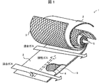
- FIG. 3 is a schematic perspective view showing a structure of a wound body provided in the acidic gas separation membrane module according to the present invention, with a partially cutout portion (Academic literature: Ind. Eng. Chem. Res. 2002, 41, 1393-1411, part of Figure 3 was modified). It is a schematic perspective view which provided the partial expansion
- the shape of the partition when the permeate-side space portion formed by the separation membrane and the permeate-side flow path member constituting the wound body includes a partition. It is a schematic plan view to explain.
- the structure of the said winding body is expand
- 1 is a schematic front view showing a central tube of a spiral acid gas separation membrane element of Example 1.
- FIG. 6 is a schematic front view showing a central tube of a spiral acidic gas separation membrane element of Comparative Example 1.
- FIG. 6 is a schematic front view showing a central tube of a spiral acidic gas separation membrane element of Example 3.
- FIG. 6 is a schematic front view showing a developed structure of a spiral acidic gas separation membrane element wound body of Example 4.
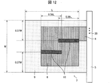
- FIG. 10 is a schematic front view showing a developed structure of a spiral wound acidic gas separation membrane element structure of Example 5. It is a schematic front view which expand
- a to B means “A or more and B or less”.
- a spiral acidic gas separation membrane element includes a separation functional layer including an acidic gas carrier that reversibly reacts with acidic gas, a resin for acidic gas separation membrane, and a support layer made of a porous membrane.
- a spiral acidic gas separation membrane element including a wound body in which a membrane, a supply-side channel material, and a permeate-side channel material are wound around a central tube in a stacked state, and the central tube is the permeate-side channel
- a hole group that communicates a space portion on the transmission side formed of a material with a space portion inside the central tube, and the hole group is unevenly distributed on one end side of the central tube. It is a configuration.
- acidic gas refers to gas which shows acidity, such as a carbon dioxide and hydrogen sulfide.
- carbon dioxide CO 2
- acid gas is taken as an example of the acid gas.
- the spiral acidic gas separation membrane element 1 includes an acidic gas carrier that reversibly reacts with acidic gas, and a separation functional layer including a resin for acidic gas separation membrane, A separation membrane 2 having a support layer made of a porous membrane, a supply-side channel material 3, and a permeation-side channel material 4 are provided with a wound body wound around a central tube 5 in a laminated state.
- the wound body may be cylindrical or rectangular, but is preferably cylindrical in consideration of housing in the housing.
- the spiral acidic gas separation membrane element 1 is configured by fixing the wound body with a fixing member such as a reinforcing tape or a telescope prevention plate (ATD) so that the wound body does not spread.
- the reinforcing tape prevents the winding body from being unwound by being wound around the outer periphery of the winding body.
- the telescope prevention plate is attached to both ends of the wound body, and prevents the telescopic phenomenon of the wound body during use of the spiral acidic gas separation membrane element.
- a reinforcing material is further wound around the outer periphery of the wound body. Examples of the reinforcing material include a reinforcing material in which a glass fiber is impregnated with an epoxy resin. The epoxy resin is preferably cured after winding the reinforcing material.
- the separation membrane 2 includes at least a separation functional layer including an acidic gas carrier that reacts reversibly with an acidic gas and a resin for the acidic gas separation membrane, and a support layer made of a porous membrane that supports the separation functional layer. ing.
- the separation membrane 2 has the property of being permeable to acidic gases such as CO 2 and water vapor, but difficult to permeate other gases, and utilizes the difference between the solubility of gas molecules in the membrane and the diffusivity in the membrane.
- acidic gases such as CO 2 and water vapor
- the separation membrane 2 has an acid gas permeation amount that varies depending on the humidity. The higher the humidity, the greater the acid gas permeation amount.
- reaction formula (1) are acidic gases carbon dioxide (CO 2), in the case of using the acid gas carrier (CO 2 carrier) as cesium carbonate (Cs 2 CO 3), CO 2 and CO 2 carrier Shows the reaction.
- the symbol “ ⁇ ” in the reaction formula (1) indicates that this reaction is a reversible reaction.
- the acid gas separation membrane resin constituting the separation functional layer may be a hydroxyl group or an ion exchange.
- a hydrophilic resin having a hydrophilic group such as a group is preferable, and a cross-linked hydrophilic resin exhibiting high water retention when the molecular chains of the hydrophilic resin have a network structure by crosslinking is more preferable.
- a cross-linked hydrophilic resin is included.
- the polymer forming the hydrophilic resin preferably has a structural unit derived from, for example, an acrylic acid alkyl ester, a methacrylic acid alkyl ester, a fatty acid vinyl ester, or a derivative thereof.
- hydrophilic polymers include polymers obtained by polymerizing monomers such as acrylic acid, itaconic acid, crotonic acid, methacrylic acid, and vinyl acetate.
- polyacrylic acid having a carboxyl group polyitaconic acid, polycrotonic acid, polymethacrylic acid, and the like, and polyvinyl alcohol having a hydroxyl group, etc.
- copolymers thereof such as acrylic acid-vinyl alcohol copolymer, acrylic acid-methacrylic acid
- examples include copolymers, acrylic acid-methyl methacrylate copolymers, and methacrylic acid-methyl methacrylate copolymers.
- polyacrylic acid which is a polymer of acrylic acid
- polymethacrylic acid which is a polymer of methacrylic acid
- polyvinyl alcohol obtained by hydrolyzing a polymer of vinyl acetate, and a copolymer of methyl acrylate and vinyl acetate
- Acrylate-vinyl alcohol copolymer, acrylic acid-methacrylic acid copolymer which is a copolymer of acrylic acid and methacrylic acid is more preferable, and polyacrylic acid and acrylate-vinyl alcohol copolymer are more preferable. preferable.
- the cross-linked hydrophilic resin may be prepared by reacting a hydrophilic polymer with a cross-linking agent, or a copolymer of a monomer that is a raw material for a hydrophilic polymer and a cross-linkable monomer. May be prepared.
- the crosslinking agent or the crosslinking monomer is not particularly limited, and a conventionally known crosslinking agent or crosslinking monomer can be used.
- crosslinking agent examples include an epoxy crosslinking agent, a polyvalent glycidyl ether, a polyhydric alcohol, a polyvalent isocyanate, a polyvalent aziridine, a haloepoxy compound, a polyvalent aldehyde, a polyvalent amine, an organometallic crosslinking agent, and a metallic crosslinking agent.
- a conventionally known crosslinking agent such as Examples of the crosslinkable monomer include conventionally known crosslinkable monomers such as divinylbenzene, N, N′-methylenebisacrylamide, trimethylolpropane triallyl ether, and pentaerythritol tetraallyl ether.
- crosslinking method examples include thermal crosslinking, ultraviolet crosslinking, electron beam crosslinking, radiation crosslinking, and photocrosslinking, and the methods described in JP-A Nos. 2003-268809 and 7-88171. Conventionally known methods can be used.
- the separation functional layer includes an acid gas separation membrane resin (for example, hydrophilic resin) and an alkali metal carbonate, alkali metal bicarbonate, and alkali metal hydroxide when the acid gas is CO 2 , for example. And at least one compound selected from the group of metal compounds (hereinafter referred to as “CO 2 carrier”).
- This CO 2 carrier is present in the separation functional layer containing the acid gas separation membrane resin, and selectively reacts with CO 2 dissolved in water present in the separation functional layer to selectively remove the CO 2. Plays a transparent role.
- the CO 2 carrier is preferably at least one alkali metal carbonate, bicarbonate or hydroxide selected from the group consisting of Na, K, Rb and Cs.
- examples of the alkali metal carbonate include sodium carbonate, potassium carbonate, rubidium carbonate, and cesium carbonate.
- examples of the alkali metal bicarbonate include sodium bicarbonate, potassium bicarbonate, rubidium bicarbonate, and cesium bicarbonate.
- examples of the alkali metal hydroxide include sodium hydroxide, potassium hydroxide, rubidium hydroxide, and cesium hydroxide.
- the CO 2 carrier an alkali metal carbonate or alkali metal hydroxide exhibiting deliquescence is preferable, and cesium carbonate or cesium hydroxide having high solubility in water is more preferable.
- alkali metal cation derived from the CO 2 carrier in addition to the alkali metal cation derived from the CO 2 carrier, various alkalis such as an alkali metal cation used for the neutralization reaction of the ion exchange group (for example, carboxyl group) of the hydrophilic resin can be used.
- ion exchange group for example, carboxyl group
- the content of all these alkali metal cations contained in the separation functional layer is preferably in the range of 1 molar equivalent to 6 molar equivalents relative to the total amount of ion exchange groups possessed by the hydrophilic resin, and 1.5 molar equivalents to 5 molar equivalents. A molar equivalent range is more preferred.
- the content of the alkali metal cation is less than 1 molar equivalent, the film forming property of the separation membrane 2 may be deteriorated.
- the content of the alkali metal cation exceeds 6 molar equivalents, the desired selective permeability of CO 2 of the separation functional layer may not be obtained.
- the coating liquid (described later) used for forming the separation functional layer included in the separation membrane 2 includes an acidic gas carrier that reversibly reacts with the acidic gas, and the acidic gas separation membrane.
- an acid gas hydration catalyst or a surfactant described later may be further added as an additive.
- the acid gas hydration catalyst improves the reaction rate between the acid gas and the carrier.
- a catalyst comprising an oxo acid compound is preferable, and in particular, an oxo of at least one element selected from the group 14 element, the group 15 element, and the group 16 element.
- a catalyst including an acid compound is preferable, and a catalyst including at least one of a tellurite compound, a selenious compound, an arsenous acid compound, and an orthosilicate compound is more preferable.
- the separation membrane 2 includes a support layer including a porous membrane with high gas permeability that does not become a diffusion resistance of the gas component that has permeated the membrane, on the permeate-side flow path material 4 side.
- the support layer is preferably a porous membrane having hydrophobicity (hydrophobic porous membrane).
- a separation membrane 2 is formed by laminating a separation functional layer containing an acid gas carrier reversibly reacting with an acid gas and a resin for an acid gas separation membrane in contact with one surface of a support layer made of a porous membrane.
- the use temperature of the separation membrane 2 is 100 ° C. or higher, and thus the members such as the porous membrane constituting the separation membrane 2
- the heat resistance of is preferably 100 ° C. or higher.
- “hydrophobic” means that the contact angle of water at 25 ° C. is 90 ° or more.
- heat resistance of 100 ° C. or higher means that the shape of a member such as a porous membrane is preserved even after being stored at a temperature of 100 ° C. or higher for 2 hours. This means that curling that can be visually confirmed by melting does not occur.
- Examples of the material of the porous film constituting the support layer include polyolefin resins such as polyethylene and polypropylene, fluorine-containing resins such as polytetrafluoroethylene (PTFE), polyvinyl fluoride, and polyvinylidene fluoride, and polyphenylene sulfide (PPS). Resin materials such as polyethersulfone, polyetheretherketone (PEEK), polyimide, high molecular weight polyester, heat-resistant polyamide, aramid, and polycarbonate; inorganic materials such as metal, glass, and ceramics.
- polyolefin resins such as polyethylene and polypropylene
- fluorine-containing resins such as polytetrafluoroethylene (PTFE), polyvinyl fluoride, and polyvinylidene fluoride
- PPS polyphenylene sulfide
- Resin materials such as polyethersulfone, polyetheretherketone (PEEK), polyimide, high molecular weight polyester
- fluorine-containing resins such as PTFE, polyvinyl fluoride, and polyvinylidene fluoride, PPS, polyethersulfone, PEEK, polyimide, and ceramics are preferable, and it is easy to obtain a fine pore size.
- PTFE is more preferable for reasons such as high porosity and high separation energy efficiency.
- the thickness of the porous film is not particularly limited, but from the viewpoint of mechanical strength, it is usually preferably in the range of 10 ⁇ m to 3000 ⁇ m, more preferably in the range of 10 ⁇ m to 500 ⁇ m, and further preferably in the range of 15 ⁇ m to 150 ⁇ m.
- the average pore diameter of the pores of the porous membrane is not particularly limited, but is preferably 10 ⁇ m or less, and more preferably in the range of 0.005 ⁇ m to 1.0 ⁇ m.
- the porosity of the porous film is preferably in the range of 5% to 99%, more preferably in the range of 30% to 90%.
- the support layer may further include a reinforcing porous membrane.
- the reinforcing porous membrane is preferably laminated on the surface of the porous membrane that is not in contact with the separation functional layer.
- the reinforcing porous membrane includes a tension load applied to the support layer when the separation membrane 2 is formed, a tension load applied to the separation membrane 2 when the spiral acidic gas separation membrane element including the separation membrane 2 is manufactured, and a mixed gas.
- the acidic gas is separated from the gas, it plays a role of giving the separation membrane 2 strength capable of withstanding the pressure load applied to the separation membrane 2 and the like.
- the structure and material of the reinforcing porous membrane are not particularly limited as long as they have pressure strength and stretch resistance and good gas permeability.
- the average pore diameter is 0.001 ⁇ m or more and 10 ⁇ m or less.
- network, etc. can be selected suitably, and can be used. Among these, it is preferable that it consists of a heat resistant raw material similarly to the separation functional layer and porous membrane containing the acidic gas carrier which reacts reversibly with acidic gas and the acidic gas separation membrane resin.
- the manufacture of the separation membrane 2 includes three steps: a first step (coating liquid preparation step), a second step (coating step), and a third step (drying step).
- a first step coating liquid preparation step
- a second step coating step
- a third step drying step
- At least an acid gas separation membrane resin and a CO 2 carrier are dissolved in a medium to prepare a coating liquid.
- Examples of the medium include protic polar media such as water, alcohol such as methanol, ethanol, 1-propanol, and 2-propanol; nonpolar media such as toluene, xylene, and hexane; acetone, methyl ethyl ketone, and methyl isobutyl ketone.
- Aprotic polar media such as ketone, N-methylpyrrolidone, N, N-dimethylacetamide, N, N-dimethylformamide; and the like.
- One type of medium may be used alone, or two or more types may be used in combination as long as they are compatible.
- a medium containing at least one selected from the group consisting of water, alcohols such as methanol, ethanol, 1-propanol and 2-propanol is preferable, and a medium containing water is more preferable.
- a surfactant may be added to the coating solution as necessary.
- a surfactant By adding a surfactant to the coating liquid, the surfactant is applied to the interface between the separation functional layer and the support layer formed by the coating liquid when the coating liquid is applied to the support layer made of a porous membrane. Is unevenly distributed, the wettability with the hydrophobic support layer is improved, and the unevenness of the film thickness is improved.
- the surfactant is not particularly limited, and examples thereof include polyoxyethylene polyoxypropylene glycols, polyoxyethylene alkylphenyl ethers, polyoxyethylene alkyl ethers, fluorine surfactants, and silicone surfactants. Conventionally known surfactants can be used.
- the surfactant one type may be used alone, or two or more types may be used in combination.
- the prepared coating liquid is applied to the surface on one side of the support layer to form a coating film.
- the temperature of the coating liquid in the second step may be appropriately determined according to the composition and concentration, but if the temperature is too high, the medium will evaporate from the coating liquid and the composition and concentration may change.
- the temperature is preferably 15 ° C. or higher, more preferably room temperature (20 ° C.) or higher, and a temperature of 5 ° C. or lower than the boiling point of the medium being used. A range is preferred.
- the temperature of the coating liquid in the second step is preferably in the temperature range of 15 ° C. to 95 ° C.
- the method of applying the coating liquid to the support layer is not particularly limited. For example, spin coating, bar coating, die coating, blade coating, air knife coating, gravure coating, roll coating coating, spray coating, dip coating, comma roll. Method, kiss coat method, screen printing, ink jet printing and the like.
- the coating amount of the coating liquid, basis weight range of 1g / m 2 ⁇ 1000g / m 2 ( solid content per unit area) is preferably in the range of 5g / m 2 ⁇ 750g / m 2 , more preferably, 10 g / A range of m 2 to 500 g / m 2 is more preferable.
- the adjustment of the basis weight can be controlled by the coating film formation speed (for example, the conveying speed of the support layer), the concentration of the coating liquid, the discharge amount of the coating liquid, and the like. Moreover, you may make it apply
- the medium is removed from the formed coating film.
- a method for removing the medium is not particularly limited, and a conventionally known method can be adopted. However, a method of evaporating and removing the medium by blowing heated air or the like and drying the coating film is preferable. Specifically, for example, the coating material (support layer on which the coating film is formed) is carried into a ventilation drying furnace adjusted to a predetermined temperature and a predetermined humidity, and the medium may be removed by evaporation from the coating film. Thereby, a separation functional layer is formed.
- the drying temperature of the coating film may be appropriately determined according to the medium of the coating liquid and the type of the porous film that is the support layer. In general, the temperature is preferably higher than the freezing point of the medium and lower than the melting point of the porous membrane, and is generally in the range of 80 ° C. to 200 ° C.
- the third step is performed until the medium contained in the coating film has a predetermined concentration or less. Specifically, the third step is preferably performed until the amount of the medium contained in the separation functional layer is in the range of 1% by weight to 34% by weight.
- the thickness of the separation functional layer is appropriately selected depending on the separation performance required for the separation membrane 2, but is usually preferably in the range of 0.1 ⁇ m to 600 ⁇ m, more preferably in the range of 0.5 ⁇ m to 400 ⁇ m, and 1 ⁇ m to 200 ⁇ m. A range is particularly preferred.
- the separation functional layer may be laminated by repeating the second step and the third step one or more times on the exposed surface of the formed separation functional layer. Thereby, the pinhole of the isolation
- the coating conditions such as the composition of the coating liquid and the coating amount and the drying conditions may be different from each other in the lamination of the respective separation functional layers, and are the same. Also good.
- the separation membrane 2 included in the spiral acidic gas separation membrane element 1 is manufactured by performing the first step, the second step, and the third step.
- the supply-side channel material 3 functions as a channel material for forming a mixed gas channel space (hereinafter sometimes referred to as a “supply-side space portion”), and a function of causing turbulence in the mixed gas. Therefore, a net-like flow path material is preferable. Since the flow path of the mixed gas changes depending on the shape of the mesh, the shape of the mesh unit cell in the supply-side flow path material 3 may be selected from shapes such as a rhombus and a parallelogram according to the purpose.
- the material of the supply-side channel material 3 is not particularly limited, but a material having heat resistance is preferable because the separation membrane 2 is used under a temperature condition of 100 ° C. or higher.
- the material of the porous membrane As the material of the porous membrane, The same materials as those listed can be preferably used. Specifically, PTFE, PPS, polyethersulfone, PEEK, polyimide, and metal are preferable, and PTFE, PPS, PEEK, and metal are more preferable.
- the flow path space formed by the supply side flow path material 3 is formed to guide the mixed gas to the inside of the wound body. Therefore, the mixed gas is continuously supplied into the wound body from the side surface direction of the supply-side flow path member 3.
- a protective porous membrane may be provided as a protective layer between the separation membrane 2 and the supply-side flow path member 3 in the wound body.
- This protective layer is separated by a gap generated between the separation functional layer constituting the separation membrane 2 and the supply-side flow path member 3 when the wound body is tightened during the production of the spiral acidic gas separation membrane element 1. It plays a role in preventing damage to the functional layer.
- the protective porous membrane is not particularly limited as long as it is a material having little friction with the supply-side flow path material 3 and good gas permeability, but the separation membrane 2 is at a temperature of 100 ° C. or higher. Therefore, a material having heat resistance is preferable.
- a material similar to the material mentioned as the material of the porous membrane forming the support layer of the separation membrane 2 can be suitably used.
- the protective porous membrane for example, a nonwoven fabric, a woven fabric, a net or the like having an average pore diameter of 0.001 ⁇ m or more and 10 ⁇ m or less can be appropriately selected and used.
- the protective layer may have a structure in which one or more kinds of porous films are laminated.
- the permeate-side channel material 4 is a channel material that forms a channel space of a permeate gas containing acid gas and water vapor that has permeated through the separation membrane 2 (hereinafter may be referred to as “permeate-side space portion”). Since it is preferable to have a function and a function of generating a turbulent flow in the permeated gas, a net-like flow path material is preferable. Since the flow path of the permeate gas varies depending on the shape of the mesh, the shape of the mesh unit cell in the permeate-side flow path material 4 may be selected from shapes such as a rhombus and a parallelogram according to the purpose.
- the material of the permeate-side channel material 4 is not particularly limited, but a material having heat resistance is preferable because the separation membrane 2 is used under a temperature condition of 100 ° C. or higher.
- a material having heat resistance is preferable because the separation membrane 2 is used under a temperature condition of 100 ° C. or higher.
- the material of the porous membrane The same materials as those listed can be preferably used. Specifically, PTFE, PPS, polyethersulfone, PEEK, polyimide, and metal are preferable, and PTFE, PPS, PEEK, and metal are more preferable.
- the permeate-side space formed by the permeate-side flow path member 4 is formed to guide the permeate gas that has permeated through the separation membrane 2 to the central tube 5.
- the supply-side flow path member 3 and the permeation-side flow path member 4 promote the turbulent flow (surface update of the membrane surface) of the mixed gas supplied and the permeated gas that has permeated through the separation membrane 2 to provide a mixed gas. It is preferable to have a function of increasing the membrane permeation rate of the acidic gas contained in the gas and a function of reducing the pressure loss of the supplied mixed gas as much as possible.
- the wound body is configured so that the supplied mixed gas and the permeated gas containing the acidic gas and water vapor that have passed through the separation membrane 2 do not mix.
- the membrane leaf (separation membrane laminate) constituting the wound body is configured such that the long rectangular separation membrane 2 is sandwiched between the long rectangular supply-side flow path materials 3. It has a structure (for example, a size of about 0.5 m to 1.5 m ⁇ 0.5 m to 1.5 m) folded in half with the separation functional layer inside. That is, the membrane leaf has a structure in which the supply-side channel material 3 is sandwiched between the single separation membranes 2.
- the membrane leaf may be formed by disposing the separation functional layer inside. In this case, one end portions of the two separation membranes 2 are bonded so that they appear to be one sheet.
- the membrane leaf is bonded to the permeate-side channel material 4 with an adhesive to form a laminate 7, and the separation membrane 2 forms a permeate-side space portion formed by the permeate-side channel material 4 and the supply A space portion on the supply side formed by the side channel material 3 is separated.
- the adhesive is not particularly limited as long as it is a material capable of adhering the membrane leaf, that is, the separation membrane 2 and the permeate-side channel material 4, but the separation membrane 2 can be used at a temperature of 100 ° C. or higher. Since it is used, a material having both heat resistance and moisture resistance is preferable.
- the adhesive examples include epoxy resin, vinyl chloride copolymer, vinyl chloride-vinyl acetate copolymer, vinyl chloride-vinylidene chloride copolymer, vinyl chloride-acrylonitrile copolymer, butadiene-acrylonitrile copolymer, Polyamide resin, polyvinyl butyral, polyester, cellulose derivative (nitrocellulose, etc.), styrene-butadiene copolymer, various synthetic rubber resins, phenol resin, urea resin, melamine resin, phenoxy resin, silicone resin, urea formamide resin, etc. Can be mentioned. Among these, an epoxy resin (epoxy adhesive resin) and a silicone resin are preferable, and an epoxy resin is more preferable.
- the adhesive may contain an inorganic or organic filler for the purpose of adjusting the viscosity during use or improving the strength after curing.
- the epoxy resin may be a compound containing an epoxy group that is cured with amines or acid anhydrides, and may be a one-component curable type or a two-component mixed type from the viewpoint of a curing method, From the viewpoint of the curing temperature, it may be a heat curing type or a room temperature curing type.
- the viscosity of the adhesive when applied to the separation membrane 2 or the like is 5,000 cP to 50,000 cP from the viewpoint of preventing the adhesive area 9 from becoming larger due to the spread of the adhesive and reducing the effective area in the separation membrane 2.
- the range of 20,000 cP to 50,000 cP is more preferable.
- the method for adhering the separation membrane 2 and the permeate-side channel material 4 is not limited to the method using an adhesive.
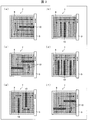
- FIG. 3 shows a case where the space portion on the permeate side formed by the separation membrane 2 and the permeate side flow path member 4 constituting the wound body has a partition in any of (a) to (f). It is a schematic plan view explaining the shape of the partition.
- a strip-shaped partition 10 that guides the flow of permeated gas may be formed in the space portion as necessary. That is, the space portion has a permeate gas flow path, for example, C-shaped (FIG. 3A), key-shaped (1) (FIG. 3B), S-shaped (FIG. 3C), key.
- You may provide the strip-shaped partition 10 led to a type
- water vapor contained in the permeated gas that has permeated the separation membrane 2 is allowed to pass through the permeate-side space portion (FIGS. 3A to 3 F) corresponding to the upstream side of the supply-side space portion. In each lower side), they are not immediately collected in the central tube 5, but are guided to the transmission side space portion (the upper side of each of FIGS. 3A to 3F) corresponding to the downstream side of the supply side space portion. Therefore, the area
- the partition 10 may be formed in an S shape (FIG. 3F) such that the upstream side of the permeate gas flow path is narrow and the downstream side is wide.
- the volume flow rate (linear velocity) per unit cross-sectional area of the permeated gas flowing through the space portion on the permeation side can be made substantially constant over the entire space.
- the number of the partitions 10 is not particularly limited, but in order to use the separation membrane 2 more efficiently, a smaller number is preferable, and one or two is more preferable.
- the width of the partition 10 is not particularly limited, but a thinner one is preferable in order to use the separation membrane 2 more efficiently.
- the length of the partition 10 is not particularly limited, but before the water vapor contained in the permeated gas that has permeated the separation membrane 2 reaches the permeation-side space portion corresponding to the downstream side of the supply-side space portion, the central tube In order to prevent the gas from being collected by the gas, it is preferable that the length of the flow channel so that the permeated gas is immediately collected by the central tube 5 is not formed. Therefore, the partition 10 is preferably formed in a band shape.
- the formation direction (longitudinal direction) of the partition 10 in the space portion may be a direction parallel to the central tube 5 or a direction orthogonal to the central tube 5.
- the formation method of the partition 10 is not particularly limited. However, when the partition 10 is formed using the adhesive that bonds the separation membrane 2 and the permeation-side flow path member 4, the separation membrane 2 and the permeation-side flow path member 4 are bonded. Since the partition 10 can be formed simultaneously, it is efficient and preferable. Therefore, it is preferable that the partition 10 is formed in a strip shape using an epoxy adhesive resin.
- the central tube 5 is a conduit for collecting the permeated gas that has permeated through the separation membrane 2 and discharging it from the spiral acidic gas separation membrane element 1.
- the material of the central tube 5 is not particularly limited. However, since the separation membrane 2 is used under a temperature condition of 100 ° C. or higher, a material having heat resistance is preferable. Since a wound body is formed by being wound, a material having mechanical strength is preferable. As the material of the center tube 5, for example, stainless steel is preferably used.
- the diameter, length, and thickness of the central tube 5 are appropriately determined according to the size of the spiral acidic gas separation membrane element 1, the number of membrane leaves, the amount of permeated gas, the mechanical strength required for the central tube 5, and the like. You only have to set it.
- the center tube 5 is preferably a circular tube when the wound body is cylindrical, and is preferably a square tube when the wound body is a rectangular tube.
- the central tube 5 has a group of holes that allow the permeation-side space portion formed by the permeation-side channel material 4 to communicate with the space portion inside the central tube 5.
- the size of each hole may be determined in consideration of the mechanical strength required for the central tube 5. Therefore, if the size of one hole cannot be increased, the number of holes may be increased.
- the hole group is a flow path direction of the mixed gas that flows through the space portion on the supply side when the spiral acidic gas separation membrane element 1 is configured, on one end side of the central tube 5. It is unevenly distributed on the end side corresponding to the downstream side.
- the permeation side flow path material 4 Since it takes time until the water vapor present in the space portion formed in (2) is collected in the central tube 5, the mixed gas and the permeated gas are kept moist and the separation efficiency of the acidic gas is maintained in a high state.
- FIG. 1 is a schematic perspective view provided with a partially cutaway portion, showing a structure of a wound body provided in an acidic gas separation membrane module according to the present invention.
- FIG. 2 is a schematic perspective view showing a structure of the acid gas separation membrane module provided with a partially developed portion.
- the acidic gas separation membrane module according to the present invention includes at least one spiral acidic gas separation membrane element 1 shown in FIGS. 1 and 2 in a housing (container) 15.
- the acid gas separation membrane module M includes a laminate 7 of the separation membrane 2, the supply-side channel material 3, and the permeation-side channel material 4, and a plurality of holes (hole groups) 30 are formed.
- At least one spiral acid gas separation membrane element 1 having a wound body wound around the central tube 5 is provided in a housing 15 made of stainless steel, for example.
- FIG. 4 is a developed cross-sectional view of the structure of the wound body included in the acidic gas separation membrane module according to the present invention, (a) is a schematic sectional view, and (b) is a schematic plan view.
- one end in the longitudinal direction of the long permeation-side channel material 4 is fixed to the outer wall of the central tube 5 with an adhesive or the like.
- a plurality of membrane leaves 6 are produced in which a long supply membrane 3 is sandwiched between a long separation membrane 2 folded in half with the separation functional layer inside.
- one membrane leaf 6 is laminated on the permeate-side channel material 4 fixed to the outer wall of the central tube 5.
- the folded fold portion of the membrane leaf 6 is directed to the central tube 5 side, and the fold portion is formed so that only the transmission-side flow channel material 4 is wound around the central tube 5 later. Separated from the tip of the material 4 (the end fixed to the outer wall of the central tube 5). That is, a region where the membrane leaf 6 is not stacked is left in the vicinity of the central tube 5 in the permeate-side flow path member 4.
- an adhesive is applied to the exposed surface of the membrane leaf 6 (the surface facing away from the permeate-side channel material 4). Specifically, along the both ends of the membrane leaf 6 in the width direction (direction parallel to the central tube 5) and one end (the side far from the central tube 5) in the length direction (the direction perpendicular to the central tube 5). Apply adhesive in a strip shape. Further, if necessary, an adhesive is applied in a band shape at a position where the partition 10 is formed. Thereafter, a new permeation-side channel material 4 and another membrane leaf 6 are laminated and bonded in this order on the exposed surface. As a result, the permeation-side space formed by the permeation-side flow path member 4 and the partition 10 are formed.
- the areas of the new permeation-side channel material 4 and the other membrane leaf 6 to be laminated are equal to or smaller than the areas of the permeation-side channel material 4 and the membrane leaf 6 previously laminated.
- the new permeation-side flow path material 4 to be laminated is close to the central tube 5 among the end portions in the length direction of the membrane leaf 6 previously laminated on the side close to the central tube 5 among the end portions in the length direction. It is preferable to laminate so as to be aligned with the side.
- the other membrane leaf 6 is separated from the central tube 5 rather than the previously laminated permeate channel material 4 so that only the permeate channel material 4 is wound around the central tube 5 later.
- an adhesive is applied to the exposed surface of the other membrane leaf 6, and similarly, a new permeation channel material 4 and another membrane leaf 6 are laminated and bonded in this order.
- the position where the adhesive is applied to the exposed surface of the other film leaf 6 may be a position overlapping with the position of the adhesive applied to the exposed surface of the previously laminated film leaf 6, and the position where a part does not overlap It may be.
- an adhesive is applied to the exposed surface of the last laminated film leaf 6. Specifically, the adhesive is applied in a strip shape along both end portions in the width direction of the film leaf 6 and one end portion (the side far from the central tube 5) in the length direction. Further, if necessary, an adhesive is applied in a band shape at a position where the partition 10 is formed. Then, the laminated body 7 is wound around the central tube 5 so as to cover the hole 30 of the central tube 5, and the permeate-side space portion formed by the permeate-side flow path member 4 is closed by the outer wall of the central tube 5. As a space, a wound body is formed. The laminate 7 is preferably wound around the central tube 5 while applying tension.
- an acid gas separation membrane module M is manufactured.
- a mixed gas containing at least an acidic gas and water vapor is continuously supplied to the supply port 31 of the space portion on the supply side formed by the supply-side flow path material 3 on the upstream side of the acidic gas separation membrane module M (in FIG. 2).
- the permeated gas that has permeated through the separation membrane 2 passes through the permeate-side space formed by the permeate-side flow path member 4 and passes through the hole 30 to the outlet (opening) of the central tube 5.
- the remaining mixed gas is continuously collected from 32 (indicated by an arrow B in FIG. 2), and the remaining mixed gas is a space portion on the supply side formed by the supply side flow path material 3 on the downstream side of the acidic gas separation membrane module M.
- the said acidic gas can be isolate
- the acid gas separation membrane module having one spiral acid gas separation membrane element 1 in the housing 15 is prepared in a number that can achieve a desired acid gas recovery rate, and arranged in parallel or in series, Good.
- “arranged in parallel” means that at least the mixed gas is distributed and introduced into the supply ports of the supply-side space portions in the plurality of acidic gas separation membrane modules M, and “arranged in series”.
- the housing 15 is preferably provided with three mixed gas inlets / outlets (separately provided with at least one permeated gas outlet).
- the two spiral acidic gas separation membrane elements 1 are apparently arranged in series in the housing 15 and the mixed gas is supplied in parallel to the two spiral acidic gas separation membrane elements 1 to separate them. It is preferable that the mixed gas that has not permeated the membrane 2 is discharged.
- the mixed gas is supplied from one of the three outlets (inlet), and the separation membrane 2 passes through the remaining two (outlet).
- the mixed gas that was not present is taken out, or the mixed gas is supplied from two (inlet) of the three outlets and the mixed gas that has not permeated the separation membrane 2 is taken out from the remaining one (outlet). preferable.
- the acidic gas separation device includes at least one acidic gas separation membrane module M configured as described above.
- the acidic gas separation device can separate the acidic gas from a mixed gas containing at least the acidic gas and water vapor more efficiently than before, and can save energy. Can be realized.
- a cylinder for supplying nitrogen (N 2 ) gas into the housing 15 ′ was attached via a valve, and a pressure gauge 35 for measuring the pressure in the housing 15 ′ was attached.
- N 2 gas at room temperature (20 ° C.) is supplied into the housing 15 ′, and a pressure of 1500 kPaG (G indicates a gauge pressure) is applied to the supply port 31 side and the other side of the spiral acidic gas separation membrane element 1. added.
- the pressure was confirmed with a pressure gauge 35.
- the pressure on the outlet 32 side of the central tube was adjusted to atmospheric pressure.
- N 2 gas permeation performance was evaluated. Specifically, the permeance of N 2 (mol / m 2 ⁇ s ⁇ kPa) is calculated based on the time change of the measured pressure, and the permeance is 5 ⁇ 10 ⁇ 8 mol / m 2 ⁇ s ⁇ kPa or less. If so, it was accepted. That is, it was evaluated that the airtightness of the spiral acidic gas separation membrane element 1 was maintained.
- the spiral acidic gas separation membrane element 1 is connected to the measuring device P so that the supply port 31 side and the discharge port 33 side of the supply-side space portion in the spiral acidic gas separation membrane element 1 are separated from each other.
- the spiral acidic gas separation membrane element 1 was installed in the housing 15 ′ so that the end portion on the side where the hole group in the central tube is unevenly located is located on the discharge port 33 side.
- a seal member 40 is attached so that the supply port 31 side and the discharge port 33 side of the supply side space portion can be separated.
- the discharge port 32 side of the central tube was led out of the housing 15 ′, and the other side was closed.
- a cylinder for supplying (CO 2 ) and a pipe for supplying water vapor (steam) were attached via a valve and a flow meter.
- a pipe 41 was attached to the discharge port 33 side of the spiral acidic gas separation membrane element 1 in the housing 15 ′.
- a gas-liquid separator 43 and a back pressure regulator 44 were connected to the pipe 41 in this order.
- the discharge port 32 side of the central tube is led out of the housing 15 ′, and a pipe 42 is attached.
- a gas-liquid separator 45 and a back pressure regulator 46 were connected to the pipe 42 in this order.
- the end of the pipe 41 was opened, and the end of the pipe 42 was connected to the gas chromatograph measuring device 47.
- MFC indicates a mass flow controller
- FC indicates a flow controller, both of which are devices for adjusting the flow rate.
- the temperature in the housing 15 ′ was adjusted to 110 ° C.
- a mixed gas humidity 80% RH
- the pressure of the mixed gas is the pipe 41 attached to the discharge port 33 side communicating with the space formed by the supply-side channel material.
- the pressure was adjusted to 500 kPaA (A is an absolute pressure) by a back pressure regulator 44 connected to.
- the pressure of the permeated gas that has permeated through the separation membrane (the pressure after the steam is condensed and removed by the gas-liquid separator 45) by the back pressure regulator 46 connected to the pipe 42 attached to the discharge port 32 side of the center pipe. , 101 kPaA (atmospheric pressure).
- the flow rate of the permeating gas was measured with a flow meter (not shown in FIG. 6) installed after the back pressure regulator 46.
- the concentration of CO 2 contained in the permeated gas was measured using a gas chromatograph measuring device 47. From the obtained measurement value, the flow rate of CO 2 contained in the permeated gas was calculated. The calculated value was defined as the CO 2 separation amount of the spiral acid gas separation membrane element 1 (unit: kg-CO 2 / hr / spiral acid gas separation membrane element).
- the temperature in the housing 15 ′ was adjusted to 118 ° C.
- a mixed gas humidity 85% RH
- the pressure of the mixed gas (the pressure after the steam is condensed and removed by the gas-liquid separator 43) is the pipe 41 attached to the discharge port 33 side communicating with the space formed by the supply-side channel material.
- the pressure was adjusted to 500 kPaA (A is an absolute pressure) by a back pressure regulator 44 connected to.
- the pressure of the permeated gas that has permeated through the separation membrane (the pressure after the steam is condensed and removed by the gas-liquid separator 45) is reduced to 160 kPaA by the back pressure regulator 46 connected to the pipe 42 attached to the discharge port 32 side. It was adjusted.
- the flow rate of the permeating gas was measured with a flow meter (not shown in FIG. 6) installed after the back pressure regulator 46.
- the concentration of CO 2 contained in the permeated gas was measured using a gas chromatograph measuring device 47. From the obtained measurement value, the flow rate of CO 2 contained in the permeated gas was calculated. The calculated value was defined as the CO 2 separation amount of the spiral acid gas separation membrane element 1 (unit: kg-CO 2 / hr / spiral acid gas separation membrane element).
- a hydrophobic PTFE porous membrane manufactured by Sumitomo Electric Fine Polymer Co., Ltd .; trade name: Poaflon / HP-010-50; ridge thickness: 50 ⁇ m, pore diameter: 0.1 ⁇ m
- a non-woven fabric made of PPS manufactured by Hirose Paper Co., Ltd .; trade name: PS0080 was attached to the back surface of the surface on which the separation functional layer was formed in the hydrophobic PTFE porous membrane.
- the separation functional layer was produced as follows. First, by adding 3 g of Cs salt type of acrylic acid-vinyl alcohol copolymer obtained by the production method described in Japanese Patent No. 5598630 and 7 g of cesium carbonate to 80 g of water, and stirring and mixing, A coating solution was obtained (first step). The amount ratio of cesium carbonate to the above copolymer was 2.3 (g-cesium carbonate / g-copolymer). The said coating liquid was apply
- the hydrophobic PTFE porous membrane on which the above coating film was formed was semi-dried at a temperature of 60 ° C. for 5 minutes or more, and then a PPS nonwoven fabric (Hirose Paper Co., Ltd.) was used as a protective layer on the exposed surface of the obtained separation functional layer.
- Product name: PS0080 was laminated. Thereafter, the hydrophobic PTFE porous membrane was further dried at a temperature of about 120 ° C. for 3 minutes or more to produce a separation membrane (third step).
- a spiral acid gas separation membrane element was produced using the above separation membrane.
- PPS net 50 ⁇ 50 mesh
- 50-150PPS The supply-side channel material.
- Three layers of PPS net 50 ⁇ 50 mesh / 60 ⁇ 40 mesh / 50 ⁇ 50 mesh) (manufactured by Dio Kasei Co., Ltd .; trade names: 50-150PPS and 60 (40) -150PPS) were used as the permeate-side channel material.
- a two-component mixed epoxy adhesive viscosity: 45,000 cP was used as an adhesive for forming the adhesive part of the membrane leaf.
- the separation membrane was folded in half with the separation functional layer on the inside so as to sandwich the supply-side flow path material, and adhered with an adhesive to form a membrane leaf.
- a stainless steel tube with an outer diameter of 1 inch was used as the central tube.
- the end side located in the downstream side of the flow direction of the mixed gas flowing in the space portion on the supply side formed by the supply side flow path material in the central tube 5
- Six holes 30 were formed so as to be unevenly distributed. That is, three holes 30 are formed at symmetrical positions on the outer wall of the central tube 5 with the central axis interposed therebetween (in FIG. 7, only three holes are visible, and the remaining three holes are on the opposite side across the central axis. Present on the outside wall).
- each hole 30 was 3 mm, and the interval between adjacent holes 30 in a row was 12.7 mm.
- the six holes 30 have the center of the hole 30 farthest from the end side (the right side in FIG. 7) when the width of the separation membrane in the stacked state, that is, the width of the stacked body 7 is W (341 mm). It provided so that it might become a position of 0.18W from the edge part of the laminated body 7 in the said edge part side.
- the spiral acid gas separation membrane element was manufactured by employing the above-described method (manufacturing process) of the spiral acid gas separation membrane element (see the above description).
- a two-component mixed epoxy adhesive (viscosity: 45,000 cP) was used as an adhesive for adhering the permeate channel material to the central tube.
- a glass fiber impregnated with a two-component mixed epoxy adhesive (viscosity: 5,000 cP) was used as a reinforcing material on the outer periphery of the spiral acidic gas separation membrane element.
- the diameter of the obtained spiral acidic gas separation membrane element was 4 inches (102 mm) and the length was 15 inches (381 mm).
- the amount of CO 2 separation of the spiral acid gas separation membrane element was measured and compared with the amount of CO 2 separation of the spiral acid gas separation membrane element of Comparative Example 1 below.
- the flow rate of the mixed gas was 4.5 Nm 3 / hr ⁇ m 2 .
- CO 2 separation of the spiral acid gas separation membrane element was 105. Therefore, by making the hole group formed in the central pipe unevenly distributed on the end side located on the downstream side of the flow path of the mixed gas flowing in the space portion on the supply side formed by the supply side flow path material, CO 2 is obtained. It was found that the separation efficiency was improved.
- Table 1 summarizes the structure of the hole group provided in the central tube and the CO 2 separation amount in the spiral acidic gas separation membrane element.
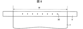
- FIG. 7 A spiral acid gas separation membrane element was produced in the same manner as in Example 1. However, instead of the central tube 5 shown in FIG. 7, 20 holes 30 are formed at uniform intervals over the entire width of the separation membrane in the laminated state, that is, the entire width of the laminated body 7, and the outer diameter is 1 inch. A stainless steel center tube 5 'was used. In other words, the central tube 5 ′ in which two rows in which ten holes 30 are arranged at a uniform interval over the entire width of the laminate 7 is used (in FIG. 8, the holes arranged in one row are schematically shown). The other holes arranged in a row are present on the outer wall on the opposite side across the central axis of the central tube 5 ').
- each hole 30 was 3 mm, and the interval between adjacent holes 30 arranged in a row was 25.4 mm.
- the flow rate of the mixed gas was 4.5 Nm 3 / hr ⁇ m 2 , and the CO 2 separation amount of the spiral acidic gas separation membrane element was measured.
- Table 1 summarizes the structure of the hole group provided in the central tube and the CO 2 separation amount in the spiral acidic gas separation membrane element.
- Example 2 The amount of CO 2 separation of the spiral acid gas separation membrane element produced in Example 1 was measured by changing the flow rate of the mixed gas to 0.3 Nm 3 / hr ⁇ m 2, and the spiral acidity of Comparative Example 2 below was measured. The amount of CO 2 separation of the gas separation membrane element was compared. As a result, when the CO 2 separation of spiral acid gas separation membrane element in Comparative Example 2 as 100, CO 2 separation of the spiral acid gas separation membrane element was 131. Therefore, by making the hole group formed in the central tube unevenly distributed on the end side located on the downstream side in the flow path direction of the mixed gas flowing through the permeation-side space formed by the supply-side flow path material, CO 2 was found to improve the separation efficiency. Table 2 summarizes the structure of the hole group provided in the central tube and the CO 2 separation amount in the spiral acidic gas separation membrane element.
- Comparative Example 2 The amount of CO 2 separation of the spiral acidic gas separation membrane element produced in Comparative Example 1 was measured by changing the flow rate of the mixed gas to 0.3 Nm 3 / hr ⁇ m 2 .
- Table 2 summarizes the structure of the hole group provided in the central tube and the CO 2 separation amount in the spiral acidic gas separation membrane element.
- Example 3 A membrane leaf was formed in the same manner as in Example 1. However, PPS net (50 ⁇ 50 mesh) (manufactured by Daio Kasei Co., Ltd .; trade name: 50-150PPS) was used as the supply-side channel material. Two layers of PPS net (60 ⁇ 40 mesh / 60 ⁇ 40 mesh) (manufactured by Daio Kasei Co., Ltd .; trade name: 60 (40) -150PPS) were used as the permeate side channel material.
- a stainless steel tube with an outer diameter of 1 inch was used as the central tube.
- the central tube 5 is unevenly distributed on the end side (right side in FIG. 9) located on the downstream side in the flow path direction of the mixed gas flowing through the space portion formed by the supply-side flow path material.
- six holes 30 were formed. That is, three holes 30 are formed at symmetrical positions on the outer wall of the central tube 5 with the central axis in between (only three holes are visible in FIG. 9, and the remaining three holes are on the opposite side with the central axis in between. Present on the outside wall).
- each hole 30 was 3 mm, and the interval between adjacent holes 30 in a row was 12.7 mm.
- the six holes 30 have the center of the hole 30 farthest from the end side (the right side in FIG. 9) when the width of the laminated separation membrane, that is, the width of the laminated body 7 is W (214 mm). It provided so that it might become a position of 0.28W from the edge part of the laminated body 7 in the said edge part side.
- the spiral acid gas separation membrane element was manufactured by employing the above-described method (manufacturing process) of the spiral acid gas separation membrane element (see the above description).
- a two-component mixed epoxy adhesive (viscosity: 45,000 cP) was used as an adhesive for adhering the permeate-side channel material to the central tube.
- a glass fiber impregnated with a two-component mixed epoxy adhesive (viscosity: 5,000 cP) was used as a reinforcing material on the outer periphery of the spiral acidic gas separation membrane element.
- the diameter of the obtained spiral acidic gas separation membrane element was 2 inches (51 mm), and the length was 10 inches (254 mm).
- the amount of CO 2 separation of the spiral acid gas separation membrane element was measured and compared with the amount of CO 2 separation of the spiral acid gas separation membrane elements of Examples 4-6.
- the flow rate of the mixed gas was set to 0.1 Nm 3 / hr ⁇ m 2 .
- Table 3 summarizes the structure of the holes in the central tube in the spiral acidic gas separation membrane element and the partition structure of the space portion on the permeate side and the CO 2 separation amount.
- Example 4 Spiral Acid Gas Separation Membrane Element with Partitions
- a spiral acid gas separation membrane element was produced in the same manner as in Example 3. However, in the spiral acidic gas separation membrane element, as shown in FIG. 10, three partitions 10 were formed in the permeate-side space formed by the permeate-side flow path member 4. As an adhesive for forming the partition 10, an adhesive for forming an adhesive portion of the membrane leaf was diverted (two-component mixed epoxy adhesive (viscosity: 45,000 cP)).
- the length of the partition 10 is upstream of the mixed gas flow path direction (from the bottom to the top in FIG. 10) when the width of the separation membrane in the stacked state, that is, the width of the stacked body 7 is W. It formed so that it might reach to the position of 0.6W from the edge part side (lower side in FIG. 10). Further, the position (center line) of the partition 10 is the length of the separation membrane in the laminated state, that is, the length of the laminated body 7 (however, only the permeation side flow path member 4 is wound around the central tube 5.
- each partition 10 (Excluding the remaining portion) is L, so that the center tube 5 is positioned at 0.16L, 0.34L (0.16L + 0.18L), 0.52L (0.16L + 0.18L + 0.18L) It was formed parallel to the central tube 5.
- the width of each partition 10 was 13 mm.
- the amount of CO 2 separation of the spiral acid gas separation membrane element was measured and compared with the amount of CO 2 separation of the spiral acid gas separation membrane element of Example 3.
- the flow rate of the mixed gas was set to 0.1 Nm 3 / hr ⁇ m 2 .
- CO 2 separation of the spiral acid gas separation membrane element was 113. Therefore, it was found that the separation efficiency of CO 2 is improved by forming a partition in the space portion formed by the permeate-side channel material.
- Table 3 summarizes the structure of the holes in the central tube in the spiral acidic gas separation membrane element and the partition structure of the space portion on the permeate side and the CO 2 separation amount.
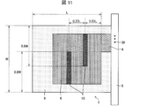
- Example 5 In the same manner as in Example 3, a spiral acid gas separation membrane element was produced. However, in the spiral acidic gas separation membrane element, as shown in FIG. 11, two partitions 10 were formed in the permeate-side space formed by the permeate-side flow path member 4. As an adhesive for forming the partition 10, an adhesive for forming an adhesive portion of the membrane leaf was diverted (two-component mixed epoxy adhesive (viscosity: 45,000 cP)).
- the width of the separation membrane in the laminated state that is, the width of the laminated body 7 is W
- the length of the partition 10 on the side close to the central tube 5 is the flow direction of the mixed gas (from the bottom to the top in FIG. 11).
- the partition 10 on the side far from the central tube 5 is formed to reach a position of 0.6 W from the end side (upper side in FIG. 11) located on the downstream side in the direction of It was formed so as to reach the position of 0.6 W from the end side (the lower side in FIG. 11) located on the upstream side of the channel.
- the length of the separation membrane in the laminated state that is, the length of the laminated body 7 (excluding the portion left so that only the permeate-side flow path material 4 is wrapped around the central tube 5) is L
- the partition 10 on the side far from the center tube 5 is positioned at the position (center line) of the partition 10 on the side far from the center tube 5 so that the position (center line) of the partition 10 on the side close to the tube 5 is 0.23 L from the center tube 5.
- the width of each partition 10 was 13 mm.
- the amount of CO 2 separation of the spiral acid gas separation membrane element was measured and compared with the amount of CO 2 separation of the spiral acid gas separation membrane element of Example 3.
- the flow rate of the mixed gas was set to 0.1 Nm 3 / hr ⁇ m 2 .
- CO 2 separation of the spiral acid gas separation membrane element was 111. Therefore, it has been found that the separation efficiency of CO 2 is improved by forming a partition in the permeate side space formed by the permeate side channel material.
- Table 3 summarizes the structure of the holes in the central tube in the spiral acidic gas separation membrane element and the partition structure of the space portion on the permeate side and the CO 2 separation amount.
- Example 6 In the same manner as in Example 3, a spiral acid gas separation membrane element was produced. However, in the spiral acidic gas separation membrane element, as shown in FIG. 12, two partitions 10 were formed in the permeate-side space formed by the permeate-side flow path member 4. As an adhesive for forming the partition 10, an adhesive for forming an adhesive portion of the membrane leaf was diverted (two-component mixed epoxy adhesive (viscosity: 45,000 cP)).
- the central tube 5 When the length of the separation membrane in the laminated state, that is, the length of the laminated body 7 (however, except for the portion left so that only the permeate-side channel material 4 is wound around the central tube 5) is L, the central tube 5
- the length of the partition 10 on the side close to the center is 0. 0 from the end portion near the center tube 5 of the laminated body 7 excluding the portion left so that only the permeate-side channel material 4 is wound around the center tube 5.
- the partition 10 that is formed so as to reach the position of 38L and is far from the central tube 5 has a length of 0.38L (excluding the adhesive portion 9 from the tip of the laminate 7). It formed so that it might reach to 0.67L) from the front-end
- the position (center line) of the partition 10 on the side close to the central tube 5 is downstream in the flow direction of the mixed gas.
- the partition 10 on the side far from the central tube 5 has a position (center line) at the position (center line) so that the position is 0.37 W from the end side (upper side in FIG. 12) located on the side.
- Each of them was formed so as to be orthogonal to the center tube 5 so as to be 0.37 W from the end side (the lower side in FIG. 12) located on the upstream side.
- the width of each partition 10 was 13 mm.
- the amount of CO 2 separation of the spiral acid gas separation membrane element was measured and compared with the amount of CO 2 separation of the spiral acid gas separation membrane element of Example 3.
- the flow rate of the mixed gas was set to 0.1 Nm 3 / hr ⁇ m 2 .
- CO 2 separation of the spiral acid gas separation membrane element was 167. Therefore, it has been found that the separation efficiency of CO 2 is improved by forming a partition in the permeate side space formed by the permeate side channel material.
- Table 3 summarizes the structure of the holes in the central tube in the spiral acidic gas separation membrane element and the partition structure of the space portion on the permeate side and the CO 2 separation amount.
- the spiral acidic gas separation membrane element, acidic gas separation membrane module, and acidic gas separation device of the present invention can separate the acidic gas from a mixed gas containing at least the acidic gas and water vapor more efficiently than before,
- CO 2 or the like from a synthetic gas synthesized at a large-scale plant producing hydrogen, urea, or the like, or a mixed gas containing at least an acid gas and water vapor, such as natural gas or exhaust gas. It can be widely used in the process of separating acid gases.
Landscapes
- Chemical & Material Sciences (AREA)
- Chemical Kinetics & Catalysis (AREA)
- Engineering & Computer Science (AREA)
- Analytical Chemistry (AREA)
- General Chemical & Material Sciences (AREA)
- Oil, Petroleum & Natural Gas (AREA)
- Inorganic Chemistry (AREA)
- Dispersion Chemistry (AREA)
- Health & Medical Sciences (AREA)
- Biomedical Technology (AREA)
- Environmental & Geological Engineering (AREA)
- Separation Using Semi-Permeable Membranes (AREA)
Abstract
Priority Applications (4)
| Application Number | Priority Date | Filing Date | Title |
|---|---|---|---|
| JP2017521911A JP6741658B2 (ja) | 2015-05-29 | 2016-05-27 | スパイラル型酸性ガス分離膜エレメント、酸性ガス分離膜モジュール、および酸性ガス分離装置 |
| CN201680031109.9A CN107614092B (zh) | 2015-05-29 | 2016-05-27 | 螺旋型酸性气体分离膜元件、酸性气体分离膜模块、以及酸性气体分离装置 |
| US15/577,037 US10525414B2 (en) | 2015-05-29 | 2016-05-27 | Spiral-wound acid gas separation membrane element, acid gas separation membrane module, and acid gas separation apparatus |
| EP16803267.0A EP3305394B1 (fr) | 2015-05-29 | 2016-05-27 | Élément de membrane de séparation de gaz acide de type spirale, module de membrane de séparation de gaz acide de type spirale, et dispositif de séparation de gaz acide |
Applications Claiming Priority (2)
| Application Number | Priority Date | Filing Date | Title |
|---|---|---|---|
| JP2015110486 | 2015-05-29 | ||
| JP2015-110486 | 2015-05-29 |
Publications (1)
| Publication Number | Publication Date |
|---|---|
| WO2016194832A1 true WO2016194832A1 (fr) | 2016-12-08 |
Family
ID=57441106
Family Applications (1)
| Application Number | Title | Priority Date | Filing Date |
|---|---|---|---|
| PCT/JP2016/065775 Ceased WO2016194832A1 (fr) | 2015-05-29 | 2016-05-27 | Élément de membrane de séparation de gaz acide de type spirale, module de membrane de séparation de gaz acide de type spirale, et dispositif de séparation de gaz acide |
Country Status (6)
| Country | Link |
|---|---|
| US (1) | US10525414B2 (fr) |
| EP (1) | EP3305394B1 (fr) |
| JP (1) | JP6741658B2 (fr) |
| CN (1) | CN107614092B (fr) |
| TW (1) | TWI681811B (fr) |
| WO (1) | WO2016194832A1 (fr) |
Cited By (8)
| Publication number | Priority date | Publication date | Assignee | Title |
|---|---|---|---|---|
| US10092880B2 (en) | 2015-05-29 | 2018-10-09 | Sumitomo Chemical Company, Limited | Spiral-wound acid gas separation membrane element, acid gas separation membrane module, and acid gas separation apparatus |
| EP3456403A1 (fr) * | 2017-09-15 | 2019-03-20 | Sumitomo Chemical Company, Limited | Procédé de séparation de gaz |
| EP3456402A1 (fr) * | 2017-09-15 | 2019-03-20 | Sumitomo Chemical Company, Limited | Procédé de séparation de gaz |
| WO2019065493A1 (fr) * | 2017-09-29 | 2019-04-04 | 住友化学株式会社 | Élément de membrane de séparation de gaz de type spiralé, module à membranes de séparation de gaz et dispositif de séparation de gaz |
| CN111491720A (zh) * | 2017-12-26 | 2020-08-04 | 东丽株式会社 | 气体分离膜、气体分离膜元件及气体分离方法 |
| JP2020131072A (ja) * | 2019-02-14 | 2020-08-31 | 住友化学株式会社 | スパイラル型の分離膜エレメントの製造方法及びその製造装置 |
| US10987622B2 (en) | 2016-04-04 | 2021-04-27 | Sumitomo Chemical Company, Limited | Acid gas separation membrane and acid gas separation method using same, acid gas separation module, and acid gas separation apparatus |
| JP2021526459A (ja) * | 2018-05-22 | 2021-10-07 | 深▲せん▼安吉爾飲水産業集団有限公司Shenzhen Angel Drinking Water Industrial Group Corporation | 全効果逆浸透膜素子及び純水機 |
Families Citing this family (11)
| Publication number | Priority date | Publication date | Assignee | Title |
|---|---|---|---|---|
| KR102313274B1 (ko) | 2014-08-11 | 2021-10-18 | 스미또모 가가꾸 가부시키가이샤 | Co2 가스 분리막용 조성물, co2 가스 분리막 및 그 제조방법과 co2 가스 분리막 모듈 |
| US10744454B2 (en) * | 2014-11-18 | 2020-08-18 | Sumitomo Chemical Company, Limited | Carbon dioxide gas separation membrane, method for manufacturing same, and carbon dioxide gas separation membrane module |
| TWI681811B (zh) * | 2015-05-29 | 2020-01-11 | 日商住友化學股份有限公司 | 螺旋形酸性氣體分離膜元件、酸性氣體分離膜模組,以及酸性氣體分離裝置 |
| CN110441101B (zh) * | 2018-05-04 | 2022-07-01 | 研能科技股份有限公司 | 气相层析设备的分离系统 |
| KR102342446B1 (ko) * | 2018-10-18 | 2021-12-22 | 주식회사 엘지화학 | 분리막 엘리먼트의 결함 검출 방법 및 분리막 엘리먼트 결함 검출 장치 |
| WO2020191557A1 (fr) * | 2019-03-22 | 2020-10-01 | 溢泰(南京)环保科技有限公司 | Maille de guidage d'écoulement, élément de membrane et ensemble filtrant |
| CN110357216B (zh) * | 2019-08-22 | 2023-05-26 | 吴红平 | 串联式双水质膜元件及其加工方法 |
| WO2022192501A1 (fr) * | 2021-03-10 | 2022-09-15 | Roco Global | Capture d'air direct de co2 à l'aide d'un contacteur stratifié de type feuille couplé à une régénération de membrane bipolaire d'électrodialyse |
| JP2025020905A (ja) * | 2023-07-31 | 2025-02-13 | セイコーエプソン株式会社 | 気体分離膜ユニットおよび気体分離装置 |
| US20250121331A1 (en) * | 2023-10-16 | 2025-04-17 | H.B. Fuller Company | Acrylate adhesive composition for the outer shell of spiral wound membrane filters |
| CN119799362A (zh) * | 2025-03-13 | 2025-04-11 | 北京环都环保科技有限公司 | 一种白油脱色和膜分离除油雾的净化方法和集成净化系统 |
Citations (4)
| Publication number | Priority date | Publication date | Assignee | Title |
|---|---|---|---|---|
| US5711882A (en) * | 1995-09-29 | 1998-01-27 | Membrane Technology And Research, Inc. | Gas separation membrane module and process |
| JP2010264421A (ja) * | 2009-05-18 | 2010-11-25 | Nitto Denko Corp | 分離膜エレメント |
| JP2014079745A (ja) * | 2012-09-28 | 2014-05-08 | Fujifilm Corp | 酸性ガス分離モジュール、酸性ガス分離装置、及びテレスコープ防止板 |
| JP2015027651A (ja) * | 2013-07-30 | 2015-02-12 | 富士フイルム株式会社 | 酸性ガス分離モジュール |
Family Cites Families (21)
| Publication number | Priority date | Publication date | Assignee | Title |
|---|---|---|---|---|
| JPH01115410A (ja) | 1987-10-27 | 1989-05-08 | Agency Of Ind Science & Technol | 溶液間浸透装置 |
| JPH0232929U (fr) | 1988-08-19 | 1990-03-01 | ||
| US5096584A (en) | 1990-01-29 | 1992-03-17 | The Dow Chemical Company | Spiral-wound membrane separation device with feed and permeate/sweep fluid flow control |
| US5034126A (en) | 1990-01-29 | 1991-07-23 | The Dow Chemical Company | Counter current dual-flow spiral wound dual-pipe membrane separation |
| EP0448973B1 (fr) | 1990-02-27 | 1995-12-20 | Toray Industries, Inc. | Module à membrane enroulée en spirale et perméable aux gaz ainsi qu'appareil et procédé pour son utilisation |
| JP2000084371A (ja) | 1998-09-08 | 2000-03-28 | Japan Organo Co Ltd | スパイラル型電気式脱イオン水製造装置 |
| JP3835543B2 (ja) * | 2002-07-05 | 2006-10-18 | ビック工業株式会社 | 流体吐出管構造体 |
| WO2007102551A1 (fr) * | 2006-03-09 | 2007-09-13 | Nitto Denko Corporation | Element membranaire en spirale et son procede de production |
| JP5204994B2 (ja) * | 2007-06-11 | 2013-06-05 | 日東電工株式会社 | スパイラル型膜エレメントおよびその製造方法 |
| JP5443773B2 (ja) | 2008-01-24 | 2014-03-19 | 株式会社ルネッサンス・エナジー・リサーチ | 二酸化炭素分離装置 |
| US8998854B2 (en) * | 2010-01-28 | 2015-04-07 | Warsaw Orthopedic, Inc. | Catheter devices and drainage systems for delivering therapeutic agents |
| TW201247297A (en) * | 2011-03-29 | 2012-12-01 | Toray Industries | Spiral type separation membrane element and method for producing the same |
| JP5623984B2 (ja) | 2011-06-17 | 2014-11-12 | 株式会社ユアサメンブレンシステム | スパイラル型ろ過モジュール及びそれを用いた液処理方法 |
| KR200459178Y1 (ko) * | 2011-07-26 | 2012-03-22 | 최건식 | 이중관형 열교환파이프 |
| EP2786798B1 (fr) * | 2011-12-02 | 2018-10-03 | Toray Industries, Inc. | Élément de membrane de séparation et son procédé de fabrication |
| JP5490281B2 (ja) * | 2012-06-20 | 2014-05-14 | 富士フイルム株式会社 | 酸性ガス分離モジュール、及び酸性ガス分離システム |
| JP2014065034A (ja) * | 2012-06-20 | 2014-04-17 | Fujifilm Corp | 酸性ガス分離層、その製造方法及びその促進輸送膜、並びに、酸性ガス分離モジュール及び酸性ガス分離システム |
| JP5961469B2 (ja) | 2012-07-25 | 2016-08-02 | 日東電工株式会社 | スパイラル型正浸透膜エレメントおよび正浸透膜モジュール |
| WO2014051117A1 (fr) | 2012-09-28 | 2014-04-03 | 富士フイルム株式会社 | Module de séparation, procédé de fabrication de module de séparation, corps tubulaire et élément de prévention du mauvais alignement d'enroulement |
| WO2014065387A1 (fr) | 2012-10-22 | 2014-05-01 | 住友化学株式会社 | Copolymère et membrane de séparation de dioxyde de carbone gazeux |
| TWI681811B (zh) * | 2015-05-29 | 2020-01-11 | 日商住友化學股份有限公司 | 螺旋形酸性氣體分離膜元件、酸性氣體分離膜模組,以及酸性氣體分離裝置 |
-
2016
- 2016-05-27 TW TW105116598A patent/TWI681811B/zh active
- 2016-05-27 US US15/577,037 patent/US10525414B2/en active Active
- 2016-05-27 JP JP2017521911A patent/JP6741658B2/ja active Active
- 2016-05-27 EP EP16803267.0A patent/EP3305394B1/fr active Active
- 2016-05-27 WO PCT/JP2016/065775 patent/WO2016194832A1/fr not_active Ceased
- 2016-05-27 CN CN201680031109.9A patent/CN107614092B/zh active Active
Patent Citations (4)
| Publication number | Priority date | Publication date | Assignee | Title |
|---|---|---|---|---|
| US5711882A (en) * | 1995-09-29 | 1998-01-27 | Membrane Technology And Research, Inc. | Gas separation membrane module and process |
| JP2010264421A (ja) * | 2009-05-18 | 2010-11-25 | Nitto Denko Corp | 分離膜エレメント |
| JP2014079745A (ja) * | 2012-09-28 | 2014-05-08 | Fujifilm Corp | 酸性ガス分離モジュール、酸性ガス分離装置、及びテレスコープ防止板 |
| JP2015027651A (ja) * | 2013-07-30 | 2015-02-12 | 富士フイルム株式会社 | 酸性ガス分離モジュール |
Cited By (22)
| Publication number | Priority date | Publication date | Assignee | Title |
|---|---|---|---|---|
| US10092880B2 (en) | 2015-05-29 | 2018-10-09 | Sumitomo Chemical Company, Limited | Spiral-wound acid gas separation membrane element, acid gas separation membrane module, and acid gas separation apparatus |
| US10987622B2 (en) | 2016-04-04 | 2021-04-27 | Sumitomo Chemical Company, Limited | Acid gas separation membrane and acid gas separation method using same, acid gas separation module, and acid gas separation apparatus |
| EP3456403A1 (fr) * | 2017-09-15 | 2019-03-20 | Sumitomo Chemical Company, Limited | Procédé de séparation de gaz |
| EP3456402A1 (fr) * | 2017-09-15 | 2019-03-20 | Sumitomo Chemical Company, Limited | Procédé de séparation de gaz |
| CN109499272A (zh) * | 2017-09-15 | 2019-03-22 | 株式会社新生能源研究 | 气体分离方法 |
| CN109499272B (zh) * | 2017-09-15 | 2022-03-11 | 株式会社新生能源研究 | 气体分离方法 |
| US10315156B2 (en) | 2017-09-15 | 2019-06-11 | Sumitomo Chemical Company, Limited | Gas separation method |
| US10441917B2 (en) | 2017-09-15 | 2019-10-15 | Sumitomo Chemical Company, Limited | Gas separation method |
| WO2019065493A1 (fr) * | 2017-09-29 | 2019-04-04 | 住友化学株式会社 | Élément de membrane de séparation de gaz de type spiralé, module à membranes de séparation de gaz et dispositif de séparation de gaz |
| CN110636896A (zh) * | 2017-09-29 | 2019-12-31 | 住友化学株式会社 | 螺旋型气体分离膜元件、气体分离膜模块以及气体分离装置 |
| KR20190139267A (ko) * | 2017-09-29 | 2019-12-17 | 스미또모 가가꾸 가부시키가이샤 | 스파이럴형 가스 분리막 엘리먼트, 가스 분리막 모듈 및 가스 분리 장치 |
| CN110636896B (zh) * | 2017-09-29 | 2022-03-25 | 住友化学株式会社 | 螺旋型气体分离膜元件、气体分离膜模块以及气体分离装置 |
| JPWO2019065493A1 (ja) * | 2017-09-29 | 2019-11-14 | 住友化学株式会社 | スパイラル型ガス分離膜エレメント、ガス分離膜モジュール、及びガス分離装置 |
| EP3603776A4 (fr) * | 2017-09-29 | 2021-05-19 | Sumitomo Chemical Company Limited | Élément de membrane de séparation de gaz de type spiralé, module à membranes de séparation de gaz et dispositif de séparation de gaz |
| KR102306543B1 (ko) * | 2017-09-29 | 2021-09-30 | 스미또모 가가꾸 가부시키가이샤 | 스파이럴형 가스 분리막 엘리먼트, 가스 분리막 모듈 및 가스 분리 장치 |
| US11213792B2 (en) | 2017-09-29 | 2022-01-04 | Sumitomo Chemical Company, Limited | Spiral-wound type gas separation membrane element, gas separation membrane module, and gas separation device |
| CN111491720A (zh) * | 2017-12-26 | 2020-08-04 | 东丽株式会社 | 气体分离膜、气体分离膜元件及气体分离方法 |
| US11383208B2 (en) | 2017-12-26 | 2022-07-12 | Toray Industries, Inc. | Gas separation membrane, gas separation membrane element, and gas separation method |
| JP2021526459A (ja) * | 2018-05-22 | 2021-10-07 | 深▲せん▼安吉爾飲水産業集団有限公司Shenzhen Angel Drinking Water Industrial Group Corporation | 全効果逆浸透膜素子及び純水機 |
| JP7231718B2 (ja) | 2018-05-22 | 2023-03-01 | 深▲せん▼安吉爾飲水産業集団有限公司 | 全効果逆浸透膜素子及び純水機 |
| JP2020131072A (ja) * | 2019-02-14 | 2020-08-31 | 住友化学株式会社 | スパイラル型の分離膜エレメントの製造方法及びその製造装置 |
| JP7257171B2 (ja) | 2019-02-14 | 2023-04-13 | 住友化学株式会社 | スパイラル型の分離膜エレメントの製造方法及びその製造装置 |
Also Published As
| Publication number | Publication date |
|---|---|
| TW201707772A (zh) | 2017-03-01 |
| US10525414B2 (en) | 2020-01-07 |
| EP3305394A1 (fr) | 2018-04-11 |
| EP3305394B1 (fr) | 2022-09-07 |
| CN107614092A (zh) | 2018-01-19 |
| EP3305394A4 (fr) | 2019-02-20 |
| US20180133654A1 (en) | 2018-05-17 |
| JPWO2016194832A1 (ja) | 2018-03-22 |
| JP6741658B2 (ja) | 2020-08-19 |
| TWI681811B (zh) | 2020-01-11 |
| CN107614092B (zh) | 2020-09-15 |
Similar Documents
| Publication | Publication Date | Title |
|---|---|---|
| JP6741658B2 (ja) | スパイラル型酸性ガス分離膜エレメント、酸性ガス分離膜モジュール、および酸性ガス分離装置 | |
| CN107635648B (zh) | 螺旋型酸性气体分离膜元件、酸性气体分离膜模块、以及酸性气体分离装置 | |
| JP6633818B2 (ja) | スパイラル型ガス分離膜エレメント、ガス分離膜モジュール、及びガス分離装置 | |
| JP6602502B2 (ja) | ガス分離膜エレメント、ガス分離膜モジュール、及びガス分離装置 | |
| US11358101B2 (en) | Spiral-wound gas separation membrane element, gas separation membrane module, and gas separation apparatus | |
| JP6573942B2 (ja) | ガス分離方法 | |
| WO2019009000A1 (fr) | Élément de membrane de séparation de gaz, module de membrane de séparation de gaz et dispositif de séparation de gaz | |
| JP7544558B2 (ja) | 分離膜エレメントの製造方法 | |
| JP7397697B2 (ja) | ガス分離膜エレメント、ガス分離膜モジュール、及びガス分離装置 | |
| US11850558B2 (en) | Composition useful for producing acidic gas separation membrane | |
| JP6573650B2 (ja) | ガス分離方法 |
Legal Events
| Date | Code | Title | Description |
|---|---|---|---|
| 121 | Ep: the epo has been informed by wipo that ep was designated in this application |
Ref document number: 16803267 Country of ref document: EP Kind code of ref document: A1 |
|
| ENP | Entry into the national phase |
Ref document number: 2017521911 Country of ref document: JP Kind code of ref document: A |
|
| WWE | Wipo information: entry into national phase |
Ref document number: 15577037 Country of ref document: US |
|
| NENP | Non-entry into the national phase |
Ref country code: DE |
|
| WWE | Wipo information: entry into national phase |
Ref document number: 2016803267 Country of ref document: EP |