WO2016195003A1 - コイル装置 - Google Patents
コイル装置 Download PDFInfo
- Publication number
- WO2016195003A1 WO2016195003A1 PCT/JP2016/066366 JP2016066366W WO2016195003A1 WO 2016195003 A1 WO2016195003 A1 WO 2016195003A1 JP 2016066366 W JP2016066366 W JP 2016066366W WO 2016195003 A1 WO2016195003 A1 WO 2016195003A1
- Authority
- WO
- WIPO (PCT)
- Prior art keywords
- segment
- main body
- end surface
- core
- casing
- Prior art date
- Legal status (The legal status is an assumption and is not a legal conclusion. Google has not performed a legal analysis and makes no representation as to the accuracy of the status listed.)
- Ceased
Links
Images








Classifications
-
- H—ELECTRICITY
- H01—ELECTRIC ELEMENTS
- H01F—MAGNETS; INDUCTANCES; TRANSFORMERS; SELECTION OF MATERIALS FOR THEIR MAGNETIC PROPERTIES
- H01F27/00—Details of transformers or inductances, in general
- H01F27/28—Coils; Windings; Conductive connections
-
- H—ELECTRICITY
- H01—ELECTRIC ELEMENTS
- H01F—MAGNETS; INDUCTANCES; TRANSFORMERS; SELECTION OF MATERIALS FOR THEIR MAGNETIC PROPERTIES
- H01F17/00—Fixed inductances of the signal type
- H01F17/04—Fixed inductances of the signal type with magnetic core
- H01F17/06—Fixed inductances of the signal type with magnetic core with core substantially closed in itself, e.g. toroid
-
- H—ELECTRICITY
- H01—ELECTRIC ELEMENTS
- H01F—MAGNETS; INDUCTANCES; TRANSFORMERS; SELECTION OF MATERIALS FOR THEIR MAGNETIC PROPERTIES
- H01F17/00—Fixed inductances of the signal type
- H01F17/04—Fixed inductances of the signal type with magnetic core
- H01F17/06—Fixed inductances of the signal type with magnetic core with core substantially closed in itself, e.g. toroid
- H01F17/062—Toroidal core with turns of coil around it
-
- H—ELECTRICITY
- H01—ELECTRIC ELEMENTS
- H01F—MAGNETS; INDUCTANCES; TRANSFORMERS; SELECTION OF MATERIALS FOR THEIR MAGNETIC PROPERTIES
- H01F27/00—Details of transformers or inductances, in general
- H01F27/02—Casings
-
- H—ELECTRICITY
- H01—ELECTRIC ELEMENTS
- H01F—MAGNETS; INDUCTANCES; TRANSFORMERS; SELECTION OF MATERIALS FOR THEIR MAGNETIC PROPERTIES
- H01F27/00—Details of transformers or inductances, in general
- H01F27/02—Casings
- H01F27/027—Casings specially adapted for combination of signal type inductors or transformers with electronic circuits, e.g. mounting on printed circuit boards
-
- H—ELECTRICITY
- H01—ELECTRIC ELEMENTS
- H01F—MAGNETS; INDUCTANCES; TRANSFORMERS; SELECTION OF MATERIALS FOR THEIR MAGNETIC PROPERTIES
- H01F27/00—Details of transformers or inductances, in general
- H01F27/06—Mounting, supporting or suspending transformers, reactors or choke coils not being of the signal type
-
- H—ELECTRICITY
- H01—ELECTRIC ELEMENTS
- H01F—MAGNETS; INDUCTANCES; TRANSFORMERS; SELECTION OF MATERIALS FOR THEIR MAGNETIC PROPERTIES
- H01F27/00—Details of transformers or inductances, in general
- H01F27/24—Magnetic cores
- H01F27/26—Fastening parts of the core together; Fastening or mounting the core on casing or support
- H01F27/266—Fastening or mounting the core on casing or support
-
- H—ELECTRICITY
- H01—ELECTRIC ELEMENTS
- H01F—MAGNETS; INDUCTANCES; TRANSFORMERS; SELECTION OF MATERIALS FOR THEIR MAGNETIC PROPERTIES
- H01F27/00—Details of transformers or inductances, in general
- H01F27/28—Coils; Windings; Conductive connections
- H01F27/29—Terminals; Tapping arrangements for signal inductances
- H01F27/292—Surface mounted devices
-
- H—ELECTRICITY
- H01—ELECTRIC ELEMENTS
- H01F—MAGNETS; INDUCTANCES; TRANSFORMERS; SELECTION OF MATERIALS FOR THEIR MAGNETIC PROPERTIES
- H01F27/00—Details of transformers or inductances, in general
- H01F27/28—Coils; Windings; Conductive connections
- H01F27/30—Fastening or clamping coils, windings, or parts thereof together; Fastening or mounting coils or windings on core, casing, or other support
- H01F27/306—Fastening or mounting coils or windings on core, casing or other support
-
- H—ELECTRICITY
- H01—ELECTRIC ELEMENTS
- H01F—MAGNETS; INDUCTANCES; TRANSFORMERS; SELECTION OF MATERIALS FOR THEIR MAGNETIC PROPERTIES
- H01F3/00—Cores, Yokes, or armatures
- H01F3/10—Composite arrangements of magnetic circuits
- H01F3/14—Constrictions; Gaps, e.g. air-gaps
-
- H—ELECTRICITY
- H01—ELECTRIC ELEMENTS
- H01F—MAGNETS; INDUCTANCES; TRANSFORMERS; SELECTION OF MATERIALS FOR THEIR MAGNETIC PROPERTIES
- H01F27/00—Details of transformers or inductances, in general
- H01F27/06—Mounting, supporting or suspending transformers, reactors or choke coils not being of the signal type
- H01F2027/065—Mounting on printed circuit boards
Definitions
- the present invention relates to a core used in a coil device equipped in a rectifier circuit, a noise prevention circuit, a resonance circuit, etc. in an AC device such as a power supply circuit and an inverter, and a coil device using the core.
- a coil device mounted on a circuit of various AC devices is configured by mounting a coil component in which a coil is wound around an annular core on a casing. To facilitate winding, a core with a gap formed in part is formed, an air-core coil pre-wound from this gap is inserted, and then the gap is backfilled with a magnetic or non-magnetic filler. (For example, refer to FIG. 10 of Patent Document 1).
- JP 2011-135091 A Japanese Patent Application No. 2013-244043
- the applicant forms the coil device as a component that is excellent in handling by mounting the coil device of Patent Document 2 on the casing to produce the coil device, and mounting the obtained coil device on the substrate. To the present invention.
- An object of the present invention is to provide a coil device in which a coil component is mounted on a casing.
- the coil device includes: A mold core including an annular magnetic body made of a magnetic material and an insulating resin coating that covers the magnetic body crosses the outer peripheral surface and the inner peripheral surface and approaches the inner peripheral direction of the mold core.
- a segment having a segment-side first end surface cut by the first cutting portion and a segment-side second end surface cut by the second cutting portion is obtained, and the main-body-side first end surface and the main body of the main body are obtained.
- a segment is arranged, and the resin coating portion
- a main body side flange projects from the edge on the end surface side toward the outer peripheral side and / or side, and the segment side flange extends from the end surface on the segment side second end surface side toward the outer peripheral side and / or side.
- the core is a projecting part, A coil wound around the core; A casing for placing the core;
- a coil device comprising: The casing has a recess into which the main body side collar and the segment side collar are inserted.
- the main body side collar part and the segment side collar part are abutted and can be inserted into the recess of the casing.
- a second resin plate is inserted between the main body side second end surface and the segment side second end surface, An interval holding member is provided in the recess so as to project the main body side collar and the segment side collar with a gap.
- the dent of the casing is formed with a pressing piece that presses in the direction in which the main body side collar part and the segment side collar part are brought close to each other.
- a locked part is formed on the opposite side to the opposing surface, A locking portion that locks the locked portion is formed in the recess of the casing.
- a guide for guiding the side surfaces of the main body side collar and the segment side collar is recessed on the inner side surface of the recess of the casing.
- a holding means for holding the lead wire of the coil is formed on the outer surface of the casing.
- the coil component can be easily produced simply by inserting the main body side collar and the segment side collar into the recess of the casing, and the obtained coil device is easy to handle.
- FIG. 1 is a side view of a core with a gap according to the present invention.
- FIG. 2 is a perspective view of the gapd core of the present invention.
- FIG. 3 is a perspective view of the magnetic body.
- FIG. 4 is a side view of the mold core before cutting.
- FIG. 5 is a bottom view of the mold core before cutting.
- FIG. 6 is a perspective view of the mold core before cutting.
- 7 is a perspective view of the mold core before cutting as viewed from the side opposite to FIG.
- FIG. 8 is a perspective view showing a process of connecting the mold cores.
- FIG. 9 is a perspective view showing a state in which the mold cores are connected.
- FIG. 10 is a side view showing the mold core cutting step.
- FIG. 10 is a side view showing the mold core cutting step.
- FIG. 11 is a perspective view showing a state where the mold core is cut into a main body and a segment.
- FIG. 12 is a perspective view of an attachment attached to a segment.
- FIG. 13 is a perspective view showing a process of attaching an attachment to a segment.
- FIG. 14 is a perspective view of a core with a gap in which a segment to which an attachment is attached is attached to the main body.
- FIG. 15 is a cross-sectional view of the resin coating portion of the core with a gap.
- FIG. 16 is a perspective view of an attachment according to a different embodiment.
- FIG. 17 is a perspective view showing a process of attaching the attachment of FIG. 16 to a segment.
- FIG. 18 is a perspective view of a core with a gap in which a segment to which the attachment of FIG. 16 is attached is attached to the main body.
- FIG. 19 is a perspective view showing a process of inserting the air-core coil into the main body.
- FIG. 20 is a perspective view showing a process of inserting a segment with an attachment into the main body inserted into the air-core coil.
- FIG. 21 is a perspective view of a core component in which an air-core coil is fitted to a core with a gap.
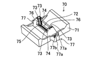
- FIG. 22 is a perspective view of a casing to which the core component is mounted.
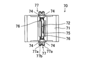
- FIG. 23 is a plan view of the casing.
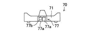
- FIG. 24 is a side view of the casing.
- FIG. 25 is a perspective view showing a process of attaching the core component to the casing.
- FIG. 26 is a perspective view showing a state in which the core component is mounted on the casing.
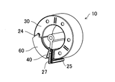
- FIG. 27 is a perspective view of a core device according to the present invention.
- FIG. 28 is a side view of a mold core for gapless core.
- FIG. 29 is a perspective view of a gapless core mold core.
- FIG. 30 is a perspective view of the attachment attached to the gapless score segment.
- FIG. 31 is a perspective view showing a process of attaching the attachment of FIG. 30 to a segment.
- FIG. 32 is a perspective view of a casing to which a gapless core is attached.
- FIG. 33 is a cross-sectional view of a core device in which a core component composed of a gapless core is mounted on a casing.
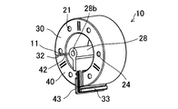
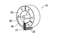
- the gap-equipped core 10 includes a main body 30 partially formed with a notch 31 (a range indicated by an arrow in FIG. 1) and a segment 40 that fits into the notch 31 of the main body 30.
- the segment 40 and the cutout portion 31 of the main body 30 from which the segment 40 is cut out have a shape in which the contact surface approaches the inner peripheral surface of the main body 30, that is, a substantially fan shape. is there.
- the cutout portion 31 of the main body 30 has a main body side first end face 32 and a main body side second end face 33 which are end faces
- the segment 40 has a segment side first end face 42 and a segment side second end face 43 which are end faces.
- the segment 40 is inserted into the notch 31 of the main body 30 so that the main body side first end face 32 and the segment side first end face 42 face each other, and the main body side second end face 33 and the segment side second end face 43 face each other. Is done.
- the main body side first end surface 32 and the segment side first end surface 42, and the main body side second end surface 33 and the segment side second end surface 43 are not in contact with each other but are opposed to each other with the gaps 11 and 11 therebetween.
- the gap-equipped core 10 having the above-described configuration can be manufactured in the following manner.
- the mold core 20 including the magnetic body 21 is produced. As shown in FIG. 3, the mold core 20 is obtained by covering the peripheral surface of a magnetic body 21 made of a magnetic material with an insulating resin coating 22 as shown in FIGS.
- the cross section of the magnetic body 21 is formed in a substantially rectangular shape, but the cross section of the magnetic body 21 may be circular, elliptical, or the like.
- the shape of the mold core 20 may be toroidal (annular), elliptical, oval, rectangular, or teardrop-shaped. 4 to 7 show a toroidal mold core 20.
- Examples of magnetic materials used for the magnetic body 21 include iron-based, iron-silicon-based, iron-aluminum-silicon-based, iron-nickel-based materials, iron-based and Co-based amorphous materials, and the like.
- the magnetic body 21 is formed by pressing or compacting a powder made of a magnetic material, a ferrite core formed by sintering a powder made of a magnetic material, and a thin plate made of a magnetic material. It can be a laminated core.
- the green compact has high dimensional accuracy and high design freedom.
- the magnetic body 21 made of a compacted body is cut using a cutting blade (grinding stone), the peripheral surface may collapse when the cutting blade is applied. Therefore, the magnetic core 21 made of a compacted body is insert-molded with an insulating resin, and the resin core 22 is formed on the peripheral surface of the magnetic body 21 as shown in FIGS. Is preferred. Thereby, it can prevent that the magnetic body 21 collapse
- the mold core 20 can also be produced by a resin powder coating method.
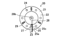
- the resin coating portion 22 is formed with a flange portion 23 protruding toward the outer peripheral side and / or the side at a position corresponding to the main body side second end surface 33 and the segment side second end surface 43 described above.
- the flange portion 23 serves as a holding portion for positioning and fixing to the jig of the cutting device and defines the cutting position. Further, as will be described later, when the coil parts 50 are arranged and cut together, the coil parts 50 are used to connect the coil parts 50 to each other.
- the collar part 23 is cut into a main body side collar part 25 and a segment side collar part 27, and the main body side collar part 25 is positioned with respect to a jig when the air core coil 51 is inserted, and the air core coil 51 is prevented from being removed. It becomes.
- the segment side flange 27 serves to prevent the air-core coil 51 from being removed when the segment 40 is mounted on the main body 30.
- the main body side flange 25 and the segment side flange 27 can be used for positioning and fixing to the casing 70 when the coil component 50 is mounted on the casing 70.
- the flange part 23 protrudes from the resin coating part 22 to the outer peripheral side and protrudes to the side.
- a main body side locked portion is formed on the side that becomes the main body side flange portion 25.
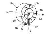
- the illustrated main body side locked portion is a groove 25 a formed in the width direction of the main body side flange 25.
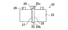
- a main body side engaging portion is formed, one of which is a concave strip 25b and the other is a convex strip 25c.
- These main body side engaging portions engage with the main body side engaging portions of adjacent coil components 50 when cutting the coil components 50 together, and serve to position and stop.
- a connecting member 28 extending to the inner side of the mold core 20 is provided so as to be continuous with the opposite side of the main body side flange 25, that is, the main body side second end surface 33. ing.
- the connecting member 28 engages with the adjacent coil components 50 when the coil components 50 are arranged and cut together, and serves to position the coil components 50.
- the connecting member 28 can be a shaft hole 28b in which one surface is a convex shaft 28a (see FIG. 7) and the other surface is fitted into the convex shaft 28a at the tip extending to the center of the mold core 20. .
- a plurality of holes 24 are formed in the side surface of the resin coating portion 22. This is formed by an insert pin for positioning the mold core 20 in the mold during insert molding. A part of these holes 24 can be used for mounting an attachment 60 described later.
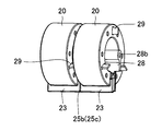
- the resin coating portion 22 is provided with a plurality of ribs 29 on one side surface.
- three ribs 29 project from the resin coating 22.
- these ribs 29 serve as spacers for securing a space between the mold cores 20 when the mold cores 20 are cut together.
- At least one rib 29 is formed on the main body 30 side and the segment 40 side.
- two ribs 29 are provided for the main body 30 and one for the segment 40.
- the rib 29 is only used when the mold core 20 is cut together, and is not necessary for the production and configuration of the coil component 50 after cutting. Therefore, after cutting the mold core 20, it is necessary to remove it. Therefore, it is desirable that the rib 29 is configured so that the periphery of the rib 29 is thin and can be excised simply by pushing it lightly and obliquely with a finger.
- the resin coating portion 22 is provided with a fitting hole 29 a in which the rib 29 is fitted on the surface opposite to the rib 29.
- the ribs 29 of the adjacent mold cores 20 are fitted into the fitting holes 29a, so that not only the interval between the mold cores 20 is secured, but also the mold cores 20 are separated from each other. Can be positioned.
- the mold core 20 having the above-described configuration is cut at two locations using a cutting blade as shown in FIGS. 10 and 11, and is cut into the main body 30 and the segment 40.
- the cutting of the mold core 20 can be performed one by one, the work efficiency can be increased as much as possible by connecting the plurality of mold cores 20 side by side and cutting them together.
- the mold cores 20 are connected to each other. More specifically, as shown in FIG. 8 and FIG. 9, a plurality of mold cores 20 are arranged, and the recess 25 b of the flange 23 of the mold core 20 and the protrusion 25 c of the flange 23 of the adjacent mold core 20 are arranged. While engaging, the convex shaft 28a of the connection member 28 and the shaft hole 28b are engaged. At this time, the ribs 29 abut against the side surfaces of the adjacent mold cores 20 to ensure an interval between them. In addition, when the fitting hole 29a is formed in the resin coating part 22, it is useful also for positioning of the mold cores 20 by fitting the rib 29 in the fitting hole 29a of the adjacent mold core 20. FIG.
- two mold cores 20 are connected side by side for easy understanding of the description, but the number is not limited to two as long as it is plural. It is preferable to connect 5 to 10 mold cores 20 and cut them together.
- a cutting blade is inserted into the arranged mold cores 20, and the mold cores 20 are cut as shown in FIGS.
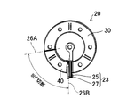
- the cutting is performed at two locations of the first cutting portion 26A and the second cutting portion 26B so that the mold core 20 is divided into the main body 30 and the segment 40 by cutting.
- the 2nd cutting part 26B is implemented in the collar part 23.
- FIG. The cutting into the first cutting part 26A and the second cutting part 26B can be performed simultaneously, or after one of the cuttings, the other cutting may be performed.
- the angle formed by the first cutting portion 26A and the second cutting portion 26B is 90 ° or less, and in the illustrated embodiment, the angle formed by these is 80 °.
- the rib 29 is not shown, but when the mold core 20 is cut, the segment 40 may drop at the end of cutting. Therefore, it is desirable to hold the rib 29 with a jig or the like to prevent the fall, particularly when performing the second cut.
- the cutting of the mold core 20 can be performed with a rotating cutting blade or the like.
- a metal-bonded diamond grindstone can be exemplified.
- cutting the mold core 20 cutting cannot be performed with a cutting margin of zero, and a cutting margin according to the thickness of the cutting blade is required. That is, the segment 40 becomes smaller by the cutting allowance than the notch 31 of the main body 30 where the mold core 20 is cut and the segment 40 is cut.
- This cutting allowance corresponds to the gap 11. Therefore, a cutting blade having a blade thickness that matches the width of the gap 11 may be employed.
- a cutting blade having a blade thickness of 0.5 mm to 1.2 mm or a blade thickness thinner than 0.7 mm is preferably used.
- widths of the gaps 11 and 11 can be the same, they may be different widths.
- cutting blades having different blade thicknesses may be used in the first cutting portion 26A and the second cutting portion 26B in accordance with the gap width.
- the end surface is compared with the configuration in which the end surfaces are directly abutted. Even if the surface roughness is reduced, the influence on the inductance can be reduced. Therefore, there is an advantage that the cutting speed of the mold core 20 by the cutting blade can be increased and the efficiency of the cutting operation can be improved.
- the mold core 20 is divided into a main body 30 having a cutout portion 31 cut out of the segment 40 and a segment 40 having a substantially fan shape.
- the main body 30 from which the segment 40 is cut out includes a main body side first end face 32 cut by the first cutting part 26A and a main body side second end face 33 cut by the second cutting part 26B. And a substantially C-shaped member having a cutout segment 40 and a cutout 31 having a cutting allowance between the main body side first end surface 32 and the main body side second end surface 33. It is.
- the notch 31 has the main body side first end surface 32 and the main body side second end surface 33 approaching in the inner circumferential direction, and the angle formed by the main body side first end surface 32 and the main body side second end surface 33 is The angle is the same as the angle formed by the first cutting portion 26A and the second cutting portion 26B toward the inner peripheral side of the mold core 20.
- the segment 40 also has a segment side first end face 42 cut by the first cutting part 26A and a segment side second end face 43 cut by the second cutting part 26B.
- the segment-side first end face 42 and the segment-side second end face 43 are substantially fan-shaped members that approach toward the inner circumferential direction.
- the angle formed by the segment-side first end surface 42 and the segment-side second end surface 43 of the segment 40 is the same as the angle formed by the first cut portion 26A and the second cut portion 26B toward the inner peripheral side of the mold core 20. is there.
- the ribs 29 that are no longer needed are cut off.
- the rib 29 can be easily excised simply by pushing it lightly and diagonally with a finger by forming the periphery thinly.
- the main body 30 and the segment 40 from which the rib 29 has been removed are shown in FIGS. 1 and 2 described above.
- the core 10 with a gap can secure the gap 11 by inserting a nonmagnetic spacer between the main body 30 and the segment 40.
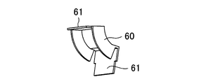
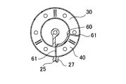
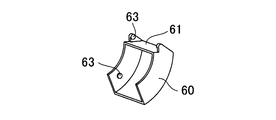
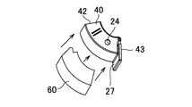
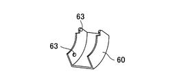
- the spacer includes two resin plates 61 and 61 that contact the segment side first end surface 42 and the segment side second end surface 43 of the segment 40 as the inner peripheral side of the segment 40.
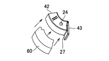
- the shape of the attachment 60 connected along the side it can integrate with the segment 40 and can handle it easily.
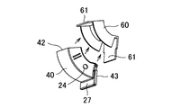
- a boss that fits into the hole 24 by the insert pin of the segment 40 is provided on the inner side surface of the attachment 60, and the attachment 60 can be easily attached to the segment 40 by fitting the boss into the hole 24. Can be attached to.
- FIG. 14 is a perspective view in which the segment 40 with the attachment 60 attached from the inner peripheral side is attached to the main body 30, and FIG. 15 is a cross-sectional view of the resin coating portion 22. Referring to FIG. 15, it can be seen that resin plates 61, 61 are interposed at the opposing positions of the main body 30 and the end faces of the segment 40.
- the segment side collar 27 becomes in the way, so the attachment 60 abuts on the segment side first end face 42 as shown in FIGS.
- the resin plate 61 is integrally formed so as to cover the outer peripheral side and the side of the segment 40, and the segment side second end surface 43 is bonded to the resin plate separately, or the gap 11 is formed by the interval holding member 76 of the casing 70 described later. It is sufficient to secure it.
- the attachment 60 can be easily attached to the segment 40 by arranging the boss 63 in the hole 24 by the insert pin of the segment 40 on the side surface of the attachment 60.
- the segment 40 can be easily attached to the main body 30 by extending the segment side first end face 42, forming the boss 63 on the inner surface thereof, and fitting the boss 63 into the hole 24 by the insert pin of the main body 30. Can be installed.
- the segment 40 is cut out from the main body 30, the main body 30 and the segment 40 have the same magnetic characteristics and the like. Therefore, extremely stable magnetic characteristics and the like can be exhibited as compared with the case where the segment is formed from another member.
- the step of forming the segment from another member can be eliminated, and in addition, the loss of raw materials is almost all. Therefore, the production efficiency can be increased as much as possible.
- the width of the gap 11 can be adjusted by the thickness of the cutting blade.
- FIG. 19 shows a state in which the air-core coil 51 is inserted into the main body 30.
- the convex shaft 28a (see FIG. 7) and the shaft hole 28b of the connecting member 28 are positioned in the device, and the main body side flange By sandwiching 25 with a jig, the main body 30 can be fixed in a non-rotatable manner. And the air-core coil 51 should just be inserted in this state. Since the main body side flange 25 protrudes from the main body 30, the air core coil 51 is prevented from being removed.
- the coil component 50 can be fixed.
- Produced. 20 and 21 are examples of inserting the segment 40 to which the attachment 60 shown in FIGS. 12 to 15 is attached.
- the segment 40 is fixed to the main body 30 by applying an adhesive to the resin plates 61 and 61 (spacers) facing the main body side first end surface 32 and the main body side second end surface 33, respectively. Can do.
- resin plates 61 and 61 are bonded and fixed as spacers to the segment side first end surface 42 and the segment side second end surface 43 of the segment 40, respectively, and the segment 40 is attached to the cutout portion 31 of the main body 30. Just plug it in.
- the main body 30 and the segment 40 are annular, and as shown in FIG. 21, a coil component 50 wound with an air-core coil 51 is obtained.
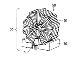
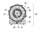
- the produced coil component 50 is mounted on a casing 70 for mounting on a substrate or the like to form a coil device 55 as shown in FIG.
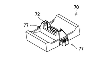
- the casing 70 is configured with a base 71 that is lowered toward the center in accordance with the outer peripheral shape of the coil component 50 as a base.
- the center of the base 71 has standing walls whose side surfaces protrude upward. On the inner surfaces of these standing walls, there are flange fixing portions to which the body side flange 25 and the segment side flange 27 of the coil component 50 are attached. Is formed.
- the flange fixing portion is a recess 72 in the present embodiment. The main body side collar 25 and the segment side collar 27 are inserted into the recess 72 and fixed.
- guides 73 for guiding the side surfaces of the main body side collar 25 and the segment side collar 27 are provided on both sides, and on the opposing surfaces of the main body side collar 25 and the segment side collar 27, respectively.
- the illustrated pressing pieces 74 and 74 are two ridges parallel to the insertion direction of the main body side collar part 25 and the segment side collar part 27.
- a casing side locking portion that engages with the main body side locked portion formed on the main body side flange 25 is projected.
- the casing-side locked portion can be a locking piece 75 protruding so as to fit into the groove 25a.
- the gap 11 is configured, a gap is generated between the main body side flange 25 and the segment side flange 27.
- the recess 72 is provided with a spacing member 76 that fits in the gap and maintains the spacing between the main body side collar 25 and the segment side collar 27.
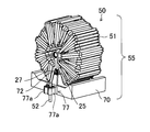
- the casing 70 is provided with holding means 77 and 77 projecting from the side surface of the base 71 for holding the lead wires 52 and 52 (see FIG. 27) of the air-core coil 51.
- the holding means 77 includes a receiving portion 77b for holding the lead wire 52 by passing the lead wire 52 between the insertion portions 77a and 77a having elasticity bent inwardly and the tips of the insert portions 77a and 77a.
- the insert portions 77a and 77a are elastically deformed to allow passage of the lead wire 52, and the lead wire 52 that has passed passes through the insert portions 77a and 77a. Is fitted and held between the front end of the base plate and the receiving portion 77b.
- a coil device 55 is formed as shown in FIG. 26 by attaching the coil component 50 to the casing 70 having the above configuration.
- the coil component 50 is attached to the casing 70 by inserting the main body side collar part 25 and the segment side collar part 27 into the recess 72 serving as the collar part fixing part. More specifically, the main body side collar 25 and the segment side collar 27 are fitted into the recess 72 by pressing both sides of the main body side collar 25 and the segment side collar 27 through the guide 73, and the presser piece 74, It is inserted while being pushed by 74. Further, between the main body side collar part 25 and the segment side collar part 27, a spacing member 76 protruding from the bottom surface of the recess 72 is fitted.
- the groove 25a which is the main body side locked portion formed in the main body side flange 25
- the locking piece 75 which is the casing side locking portion
- the gap-equipped core 10 has been described.
- the main body-side first end face 32 and the segment-side first end face 42, and the main-body-side second end face 33 and the segment-side second end face 43 are abutted without a gap.
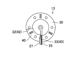
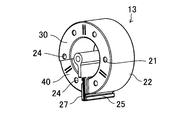
- the present invention can also be applied to the gapless score 13. That is, even in the case of the gapless score 13, the above-described cutting method of the mold core 20 can be employed.
- FIG. 30 shows the attachment 60 of the segment 40 employed in the gapless score 13.
- the attachment 60 covers only the side surface and the inner surface of the segment 40, and the segment side first end surface 42 and the segment side second end surface 43 remain exposed.
- this attachment 60 has a boss 63 that fits into the hole 24 formed in the resin coating portion 22 by an insert pin, and the boss 63 fits into the hole 24 of the segment 40.
- the attachment 60 can be attached to the segment 40.
- the boss 63 that extends longer than the segment 40 may be fitted into the hole 24 of the main body 30.
- the process of mounting the coil component 50 on the casing 70 to produce the coil device 55 is the same as in the above embodiment.
- a sectional view of the manufactured coil device 55 is shown in FIG.
- the recess 72 of the casing 70 may be formed to have a narrow width by an amount that does not require a gap.
- the segment 40 can be returned to another main body 30 without returning to the main body 30 from which the segment 40 is cut out.
- the main body side first end face 32 and the segment side first end face 42 are opposed to each other, and the main body side second end face 33 and the segment side second end face 43 are opposed to each other.
- the end surface 32 and the segment side second end surface 43 may be opposed to each other, and the main body side second end surface 33 and the segment side first end surface 42 may be opposed to each other.
- the gaps 11 and 11 are formed between the main body side first end surface 32 and the segment side first end surface 42 and between the main body side second end surface 33 and the segment side second end surface 43, respectively.
- the gap core 10 provided and the gapless score 13 in which any end face is abutted have been described, the gap 11 may be formed only between any end faces, and the other end face may be abutted to be gapless.
- the gap between the main body side first end face 32 and the segment side first end face 42 is made to be gapless, and the gap 11 is provided between the main body side second end face 33 and the segment side second end face 43, so that the coil The occurrence of leakage magnetic flux in 51 can be suppressed.
- the magnetic flux interlinking with the coil 51 becomes small, eddy current loss can be reduced and heat generation can be suppressed.
- the main body side second end surface 33 and the segment side second end surface 43 are abutted to be gapless, and the gap 11 is provided between the main body side first end surface 32 and the segment side first end surface 42.
- the initial inductance is reduced and the saturation magnetic characteristic is lowered, but there is an advantage that the gradient of the DC superimposition characteristic can be reduced.
Landscapes
- Engineering & Computer Science (AREA)
- Power Engineering (AREA)
- Microelectronics & Electronic Packaging (AREA)
- Chemical & Material Sciences (AREA)
- Composite Materials (AREA)
- Coils Or Transformers For Communication (AREA)
Abstract
Description
巻線を容易に行なうために、一部に空隙を形成したコアを形成し、この空隙から予め巻線された空芯コイルを挿入し、その後、空隙を磁性又は非磁性の充填材によって埋め戻している(たとえば、特許文献1の図10参照)。
磁性材料からなる環状の磁性体と前記磁性体を覆う絶縁性の樹脂被覆部とを含むモールドコアを、外周面と内周面を横断し、互いにモールドコアの内周方向に向けて接近する第1切断部と第2切断部で切断し、前記第1切断部で切断された本体側第1端面と、前記第2切断部で切断された本体側第2端面と、を有する本体と、前記第1切断部で切断されたセグメント側第1端面と、前記第2切断部で切断されたセグメント側第2端面と、を有するセグメントを得て、前記本体の前記本体側第1端面と前記本体側第2端面との間に形成された切欠き部に、前記本体側第1端面と前記セグメント側第1端面、前記本体側第2端面と前記セグメント側第2端面が、夫々対向するよう前記セグメントを配置してなり、前記樹脂被覆部は、前記本体側第2端面側の端縁から外周側及び/又は側方に向けて本体側鍔部が突設されると共に、前記セグメント側第2端面側の端面から外周側及び/又は側方に向けてセグメント側鍔部が突設されてなる、コアと、
前記コアに巻回されるコイルと、
前記コアを載置するケーシングと、
を具えるコイル装置であって、
前記ケーシングは、前記本体側鍔部と前記セグメント側鍔部が挿入される凹みを有する。
前記凹みには、前記本体側鍔部と前記セグメント側鍔部を隙間を存して保持する間隔保持部材が突設されている。
前記ケーシングの前記凹みは、前記本体側鍔部と前記セグメント側鍔部を接近させる方向に押圧する押え片が形成されている。
前記ケーシングの前記凹みには、前記被係止部を係止する係止部が形成されている。
モールドコア20は、図3に示すように、磁性材料からなる磁性体21の周面を、図4乃至図7に示すように絶縁性の樹脂被覆部22で覆ったものである。
まず、モールドコア20からセグメント40を切り出した後(図11)、本体30の本体側第1端面32より予め巻線された空芯コイル51を挿入する。図19は、本体30に空芯コイル51が挿入された状態を示している。
11 ギャップ
20 モールドコア
25 本体側鍔部
27 セグメント側鍔部
30 本体
31 切欠き部
32 本体側第1端面
33 本体側第2端面
40 セグメント
42 セグメント側第1端面
43 セグメント側第2端面
50 コイル部品
51 空芯コイル
55 コイル装置
70 ケーシング
Claims (7)
- 磁性材料からなる環状の磁性体と前記磁性体を覆う絶縁性の樹脂被覆部とを含むモールドコアを、外周面と内周面を横断し、互いにモールドコアの内周方向に向けて接近する第1切断部と第2切断部で切断し、前記第1切断部で切断された本体側第1端面と、前記第2切断部で切断された本体側第2端面と、を有する本体と、前記第1切断部で切断されたセグメント側第1端面と、前記第2切断部で切断されたセグメント側第2端面と、を有するセグメントを得て、前記本体の前記本体側第1端面と前記本体側第2端面との間に形成された切欠き部に、前記本体側第1端面と前記セグメント側第1端面、前記本体側第2端面と前記セグメント側第2端面が、夫々対向するよう前記セグメントを配置してなり、前記樹脂被覆部は、前記本体側第2端面側の端縁から外周側及び/又は側方に向けて本体側鍔部が突設されると共に、前記セグメント側第2端面側の端面から外周側及び/又は側方に向けてセグメント側鍔部が突設されてなる、コアと、
前記コアに巻回されるコイルと、
前記コアを載置するケーシングと、
を具えるコイル装置であって、
前記ケーシングは、前記本体側鍔部と前記セグメント側鍔部が挿入される凹みを有する、
ことを特徴とするコイル装置。 - 前記本体側鍔部と前記セグメント側鍔部は、突き合わされて前記ケーシングの前記凹みに挿入される、
請求項1に記載のコイル装置。 - 前記本体側第2端面と前記セグメント側第2端面の間には夫々第2樹脂プレートが挿入され、
前記凹みには、前記本体側鍔部と前記セグメント側鍔部を隙間を存して保持する間隔保持部材が突設されている、
請求項1に記載のコイル装置。 - 前記ケーシングの前記凹みは、前記本体側鍔部と前記セグメント側鍔部を接近させる方向に押圧する押え片が形成されている、
請求項1乃至請求項3の何れかに記載のコイル装置。 - 前記本体側鍔部及び/又はセグメント側鍔部には、対向面とは逆側に被係止部が形成されており、
前記ケーシングの前記凹みには、前記被係止部を係止する係止部が形成されている、
請求項1乃至請求項4の何れかに記載のコイル装置。 - 前記ケーシングの前記凹みの内側面には、前記本体側鍔部と前記セグメント側鍔部の側面を案内するガイドが凹設されている、
請求項1乃至請求項5の何れかに記載のコイル装置。 - 前記ケーシングの外側面には、前記コイルの引き出し線を保持する保持手段が形成されている、
請求項1乃至請求項6の何れかに記載のコイル装置。
Priority Applications (4)
| Application Number | Priority Date | Filing Date | Title |
|---|---|---|---|
| EP16803437.9A EP3306624B1 (en) | 2015-06-03 | 2016-06-02 | Coil device |
| CN201680032145.7A CN107615416B (zh) | 2015-06-03 | 2016-06-02 | 线圈装置 |
| KR1020177034528A KR20180013938A (ko) | 2015-06-03 | 2016-06-02 | 코일 장치 |
| US15/575,067 US20180144856A1 (en) | 2015-06-03 | 2016-06-02 | Coil apparatus |
Applications Claiming Priority (2)
| Application Number | Priority Date | Filing Date | Title |
|---|---|---|---|
| JP2015113162A JP6095724B2 (ja) | 2015-06-03 | 2015-06-03 | コイル装置 |
| JP2015-113162 | 2015-06-03 |
Publications (1)
| Publication Number | Publication Date |
|---|---|
| WO2016195003A1 true WO2016195003A1 (ja) | 2016-12-08 |
Family
ID=57441308
Family Applications (1)
| Application Number | Title | Priority Date | Filing Date |
|---|---|---|---|
| PCT/JP2016/066366 Ceased WO2016195003A1 (ja) | 2015-06-03 | 2016-06-02 | コイル装置 |
Country Status (7)
| Country | Link |
|---|---|
| US (1) | US20180144856A1 (ja) |
| EP (1) | EP3306624B1 (ja) |
| JP (1) | JP6095724B2 (ja) |
| KR (1) | KR20180013938A (ja) |
| CN (1) | CN107615416B (ja) |
| TW (1) | TWI684192B (ja) |
| WO (1) | WO2016195003A1 (ja) |
Families Citing this family (6)
| Publication number | Priority date | Publication date | Assignee | Title |
|---|---|---|---|---|
| JP6055871B2 (ja) * | 2015-06-03 | 2016-12-27 | 株式会社エス・エッチ・ティ | コイル部品に用いられるモールドコアの切断方法 |
| CN108806922A (zh) * | 2017-12-11 | 2018-11-13 | 伊顿公司 | 一种电感器 |
| CN110289149A (zh) * | 2018-03-19 | 2019-09-27 | 田村(中国)企业管理有限公司 | 线圈零件 |
| TWI709021B (zh) * | 2018-03-30 | 2020-11-01 | 日商京瓷股份有限公司 | 電感用芯、電子筆用芯體部、電子筆及輸入裝置 |
| US12009130B2 (en) * | 2018-11-29 | 2024-06-11 | Autonetworks Technologies, Ltd. | Reactor |
| WO2024189662A1 (ja) * | 2023-03-10 | 2024-09-19 | キヤノンアネルバ株式会社 | X線発生装置、x線撮像装置およびモールド変圧器 |
Citations (4)
| Publication number | Priority date | Publication date | Assignee | Title |
|---|---|---|---|---|
| JPS5329527A (en) * | 1976-08-31 | 1978-03-18 | Mitsubishi Electric Corp | Rolled core with gap |
| JPH04206909A (ja) * | 1990-11-30 | 1992-07-28 | Mitsui Petrochem Ind Ltd | トランス用カットコアの製法 |
| JPH0817649A (ja) * | 1994-06-27 | 1996-01-19 | Tdk Corp | コアケース組立体 |
| JP2009123827A (ja) * | 2007-11-13 | 2009-06-04 | Nagano Japan Radio Co | コイル装置 |
Family Cites Families (13)
| Publication number | Priority date | Publication date | Assignee | Title |
|---|---|---|---|---|
| US3340489A (en) * | 1964-09-30 | 1967-09-05 | Kaiser Aluminium Chem Corp | Electrical transformer with cooling means |
| JPH0745995Y2 (ja) * | 1991-07-18 | 1995-10-18 | 北川工業株式会社 | 雑音吸収具 |
| JPH08222455A (ja) * | 1995-02-13 | 1996-08-30 | Tokin Corp | ノーマルモードチョークコイル |
| CN1049997C (zh) * | 1996-07-16 | 2000-03-01 | 冶金工业部钢铁研究总院 | 软磁铁芯元件及其制造方法 |
| US6023023A (en) * | 1996-07-19 | 2000-02-08 | Takeuchi Industrial Co., Ltd. | Noise absorbing apparatus |
| JP2000200721A (ja) * | 1999-01-07 | 2000-07-18 | Fuji Elelctrochem Co Ltd | コイル部品 |
| WO2001052277A1 (en) * | 2000-01-12 | 2001-07-19 | Koninklijke Philips Electronics N.V. | Method of manufacturing a substantially closed core, core, and magnetic coil |
| US20050001709A1 (en) * | 2003-07-03 | 2005-01-06 | Pais Martin R. | Inductive device and methods for assembling same |
| JP4607979B2 (ja) * | 2008-03-14 | 2011-01-05 | 株式会社エス・エッチ・ティ | 支持台及び台付きコイル装置 |
| CN201975251U (zh) * | 2010-04-13 | 2011-09-14 | 徐其信 | 分体式电流互感器 |
| WO2015171560A1 (en) * | 2014-05-05 | 2015-11-12 | Hubbell Incorporated | Adjustable inductor |
| CN204332662U (zh) * | 2014-10-30 | 2015-05-13 | 浙江正泰电源电器有限公司 | 一种浇注式电流互感器的新型壳体 |
| DE102015107605B4 (de) * | 2015-05-13 | 2018-01-25 | Sma Solar Technology Ag | Induktives Bauelement für Leiterplattenmontage und Wechselrichter mit einem leiterplattenmontierten induktiven Bauelement |
-
2015
- 2015-06-03 JP JP2015113162A patent/JP6095724B2/ja active Active
-
2016
- 2016-05-31 TW TW105117007A patent/TWI684192B/zh not_active IP Right Cessation
- 2016-06-02 KR KR1020177034528A patent/KR20180013938A/ko not_active Withdrawn
- 2016-06-02 EP EP16803437.9A patent/EP3306624B1/en active Active
- 2016-06-02 WO PCT/JP2016/066366 patent/WO2016195003A1/ja not_active Ceased
- 2016-06-02 US US15/575,067 patent/US20180144856A1/en not_active Abandoned
- 2016-06-02 CN CN201680032145.7A patent/CN107615416B/zh not_active Expired - Fee Related
Patent Citations (4)
| Publication number | Priority date | Publication date | Assignee | Title |
|---|---|---|---|---|
| JPS5329527A (en) * | 1976-08-31 | 1978-03-18 | Mitsubishi Electric Corp | Rolled core with gap |
| JPH04206909A (ja) * | 1990-11-30 | 1992-07-28 | Mitsui Petrochem Ind Ltd | トランス用カットコアの製法 |
| JPH0817649A (ja) * | 1994-06-27 | 1996-01-19 | Tdk Corp | コアケース組立体 |
| JP2009123827A (ja) * | 2007-11-13 | 2009-06-04 | Nagano Japan Radio Co | コイル装置 |
Non-Patent Citations (1)
| Title |
|---|
| See also references of EP3306624A4 * |
Also Published As
| Publication number | Publication date |
|---|---|
| CN107615416B (zh) | 2020-03-06 |
| EP3306624A1 (en) | 2018-04-11 |
| TWI684192B (zh) | 2020-02-01 |
| EP3306624A4 (en) | 2018-12-26 |
| EP3306624B1 (en) | 2020-01-15 |
| JP6095724B2 (ja) | 2017-03-15 |
| US20180144856A1 (en) | 2018-05-24 |
| CN107615416A (zh) | 2018-01-19 |
| KR20180013938A (ko) | 2018-02-07 |
| TW201711063A (zh) | 2017-03-16 |
| JP2016225570A (ja) | 2016-12-28 |
Similar Documents
| Publication | Publication Date | Title |
|---|---|---|
| JP6095724B2 (ja) | コイル装置 | |
| JP6095723B2 (ja) | ギャップ付きコア、これを用いたコイル部品及びコイル部品の製造方法 | |
| WO2012169043A1 (ja) | 回転電機用ロータ、回転電機、および、回転電機用ロータの製造方法 | |
| JP2014135865A (ja) | 回転電機の製造方法、ステータ | |
| JP2019205246A (ja) | インシュレータ、電機子、回転電機、巻線治具、及び巻線方法 | |
| CN107408451B (zh) | 电感元件用树脂壳体以及电感元件 | |
| JP6055871B2 (ja) | コイル部品に用いられるモールドコアの切断方法 | |
| JP4791387B2 (ja) | 電機子 | |
| CN108370179A (zh) | 芯片、分割层叠芯及定子以及分割层叠芯的制造方法 | |
| JP6552719B2 (ja) | 回転電機用電機子 | |
| JP2015041686A (ja) | リアクトルとその製造方法 | |
| JP6039538B2 (ja) | ギャップレス磁芯、これを用いたコイル装置及びコイル装置の製造方法 | |
| JP2004087668A (ja) | 鉄心及びこれを用いたコイル装置並びにこれらの製造方法 | |
| JP6126558B2 (ja) | コイル装置 |
Legal Events
| Date | Code | Title | Description |
|---|---|---|---|
| 121 | Ep: the epo has been informed by wipo that ep was designated in this application |
Ref document number: 16803437 Country of ref document: EP Kind code of ref document: A1 |
|
| WWE | Wipo information: entry into national phase |
Ref document number: 15575067 Country of ref document: US |
|
| ENP | Entry into the national phase |
Ref document number: 20177034528 Country of ref document: KR Kind code of ref document: A |
|
| NENP | Non-entry into the national phase |
Ref country code: DE |
|
| WWE | Wipo information: entry into national phase |
Ref document number: 2016803437 Country of ref document: EP |