WO2016199308A1 - Modèle de costume motif et dispositif de mesure pour modèle de costume - Google Patents
Modèle de costume motif et dispositif de mesure pour modèle de costume Download PDFInfo
- Publication number
- WO2016199308A1 WO2016199308A1 PCT/JP2015/067092 JP2015067092W WO2016199308A1 WO 2016199308 A1 WO2016199308 A1 WO 2016199308A1 JP 2015067092 W JP2015067092 W JP 2015067092W WO 2016199308 A1 WO2016199308 A1 WO 2016199308A1
- Authority
- WO
- WIPO (PCT)
- Prior art keywords
- shoulder
- length
- line
- point
- base point
- Prior art date
- Legal status (The legal status is an assumption and is not a legal conclusion. Google has not performed a legal analysis and makes no representation as to the accuracy of the status listed.)
- Ceased
Links
Images


Classifications
-
- A—HUMAN NECESSITIES
- A41—WEARING APPAREL
- A41H—APPLIANCES OR METHODS FOR MAKING CLOTHES, e.g. FOR DRESS-MAKING OR FOR TAILORING, NOT OTHERWISE PROVIDED FOR
- A41H3/00—Patterns for cutting-out; Methods of drafting or marking-out such patterns, e.g. on the cloth
-
- A—HUMAN NECESSITIES
- A41—WEARING APPAREL
- A41D—OUTERWEAR; PROTECTIVE GARMENTS; ACCESSORIES
- A41D1/00—Garments
- A41D1/02—Jackets
-
- A—HUMAN NECESSITIES
- A41—WEARING APPAREL
- A41H—APPLIANCES OR METHODS FOR MAKING CLOTHES, e.g. FOR DRESS-MAKING OR FOR TAILORING, NOT OTHERWISE PROVIDED FOR
- A41H1/00—Measuring aids or methods
- A41H1/02—Devices for taking measurements on the human body
-
- A—HUMAN NECESSITIES
- A41—WEARING APPAREL
- A41H—APPLIANCES OR METHODS FOR MAKING CLOTHES, e.g. FOR DRESS-MAKING OR FOR TAILORING, NOT OTHERWISE PROVIDED FOR
- A41H3/00—Patterns for cutting-out; Methods of drafting or marking-out such patterns, e.g. on the cloth
- A41H3/06—Patterns on paper
Definitions
- the present invention relates to a spine prototype and a measuring instrument for the spine prototype.
- each pattern is based on an upper pattern formed by integrally cutting the buttocks and left and right sleeves and a lower pattern formed by integrally cutting the front and back bodies.
- the garment is lightened, and the wearer's movement is not limited, making it easy to move and workability. It is possible to provide comfortable clothes with excellent safety.
- the arm member connected to the upper part of the front body and the back body is divided into a forearm member, a rear arm member, and a lower arm member, and the sleeve is made of at least three members, and the shape of each arm member Is curved in a certain direction, or the side edge part attached to the front body and the back body intersects at an acute angle, and the intersection of the acute angle becomes a buttock to form a necessary space for exercise in the sewing state .
- the sleeve part is lightly bent at the elbow to form a three-dimensional shape close to the curve of the arm protruding diagonally downward and forward, and the outerwear has good wearing feeling with respect to the movement of the arm front and rear, left and right It is said.
- a suit is created by stitching the left and right body parts, which are formed by dividing the main body of the back into the left and right sides from the back center line, and stitching them together at the back.
- Each body part is composed of a combination of a front body and a back body. At that time, measure the length between both shoulder widths, length, bust length, waist length, sleeve length, etc. so that it matches the body shape of the standard wearer as much as possible.
- left and right half body parts or left and right half body parts for standard backs for each body type, or specific wearers based on orders from specific people
- the left and right half body parts tailored to the body shape of the body are made, and the suit is made based on these left and right half body parts.
- the part of the upper body to be measured in the production of such a suit is limited to the part traditionally specified from ancient times such as the height, bust line, shoulder width, sleeve length, and the like.
- the conventional tailoring does not consider the measurement of the body part that is most necessary to fit the body shape, such as the inclination of the shoulder of the wearer, the shoulder length, the forward inclination of the back, and the body.
- the point that becomes the base point of the measurement part of the wearer's body shape is a point temporarily determined from the measurement values such as the chest circumference, and the ground height before and after the body is added as a correction coefficient to this point, and various points of the wearer are added to the point.
- the base point of the correct measurement site is determined by taking into account additional factors of displacement, such as different body, forward bending (back of the back), shoulder angle, length, etc., and the body shape based on the correct base point
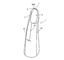
- This invention consists of a left half part and a right half part formed by dividing the outer jacket main body into left and right parts from the back center line of the back part, and a substantially elliptical shape formed by partially cutting the upper part of the center upper part of the left and right half parts.
- the left and right sleeve holes, the heel formed at the front edge of the left body part body, the chest width part in front of the sleeve hole part, the side width part below the sleeve hole part, and the back behind the sleeve hole part The upper part of the original centerline of the wearer's original back center line, formed by joining and sewing together the partially cut ends of the left and right cuffs and the back sewing lines of the left and right body parts.
- the back base point to be moved From the back base point to be moved, it moves forward by a length calculated by applying a pre-defined correction formula to the length of the chest circumference or the length around the neck, and from the moved point to about 1/4 of the movement length
- the point identified by moving vertically up the length of The point specified by the intersection of the vertical line approximately 0.5 to 0.6 times the length from the front edge to the front edge of the cuff and the absolute horizontal line from the virtual base point behind the left and right shoulders The length of the curved neck line from the back base point of the back of the back to the virtual base point before and after the left and right shoulders and the standard temporary reference point specified in the middle of the neck line.
- the length from the reference point specified in the middle of the neck line using the difference value to the ground level passing through the back of the wearer's body and the length from the chest side to the ground level
- the correct left and right shoulder front and rear base positions are determined by correcting each and the correct right and left shoulder front base points, or a line connected to the notch front
- the present invention provides a broad-type prototype characterized by the above.
- the correction formula applied to the chest circumference from the back center line when specifying the left and right shoulder back base points is (0.15 to 0.20) about 1/2 of the chest circumference. It is intended to provide a prototype of the spine characterized by multiplication.
- the correction formula applied to the length around the neck from the back center line when specifying the length around the neck is (10-15) added to the length around the neck, and the total is calculated as
- the present invention provides a broad-type prototype characterized by dividing by (5-7).
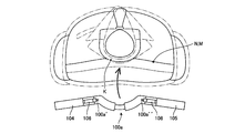
- a curved frame 100a that can be mounted and placed around the rear neck of the wearer; Left and right inclined plates 104 and 105 pivotally supported on the left and right ends of the curved frame 100a via the pivot shaft 106, and left and right shoulder front and rear base points (N, M) set on the free end of the curved frame 100a to the ground surface GL
- the curved frame 100a has a left half-curved portion 101a and a right half-curved portion 102a as separate bodies, and one of the curved portions 101a or 102a has a base end on the other side.
- the bent portion 101a or 102a is a telescopic mechanism in which the base end can be freely inserted, and the ground height measuring device includes an upper half measuring measure 121 that is suspended from the left and right shoulder front and rear base points (N, M) to the back side or the chest side downward. , And a measurement weight for a prototype with a reflection function, which is provided at the lower end of the upper half measurement measure 121 and irradiates the ground surface GL with infrared rays and receives the reflection from the ground surface GL. It is a vessel.
- the basic idea of the present invention is to measure the length of the chest circumference or neck that is an objective numerical value of the wearer, apply the correction formula to it,
- the virtual base points around the left and right shoulders are set at a certain distance and place from the back base point.
- the basic idea is to set each point of the pattern required for the spine prototype using the right and left shoulder front and back base points as the origin of all dimensions.
- the calculated value of the curved neck line calculated from the chest circumference of the actual wearer, etc., and the body front and back surfaces from the standard temporary reference point in the middle of the neck line It is characterized by the use of various elements such as the length of the distance to the ground surface, and by this method, no matter how the wearer's physical shape is different, the left and right of the shoulder of the human body and the human body are always centered on the back base point.
- the front and back shoulders have balanced “Yajirobe” postures, so that they can provide the best model with the best comfort.
- the virtual base points before and after the left and right shoulders are specified on both shoulder portions by a certain method, and the wearer's specific body shape is taken into consideration for this base point.
- the correct base point is identified, and various dimensions necessary for the back, such as the shoulder inclination and the length to the collar, are calculated based on the correct base point.
- the position of the subsequent virtual base point is specified by applying a certain correction formula to the length of the chest circumference or neck circumference of the wearer, and then the back base point and the left shoulder that should be the upper end of the wearer's original back center line
- the length of the curved scruff line between the virtual base point and the back is correct by increasing or decreasing the length of the middle part of the scruff line that passes through the chest and back from the standard temporary point to the ground.
- Identify the left shoulder back base point and correct from this correct left shoulder back base point By identifying the front shoulder base, it is possible to produce clothes that fit the body shape unique to the wearer, such as the shoulder, the cradle type, the back of the back, and the body, and it is also easy to create a pattern that represents such a measurement and the prototype of the suit, There is an effect that it is possible to produce a spine prototype that accurately fits each person's body shape without the need for highly skilled skills.
- the garment made with such a stencil prototype fits the wearer's body precisely and has a shoulder that is easy to act on, so the left and right arms do not cause unnecessary wrinkles near the back of the neck or around the shoulder when worn.
- the right and left shoulder front and back base points are temporarily identified based on the length from the back base point along the neck line, and then the right and left shoulder front and rear base points are corrected while measuring the length from the ground surface and correcting this measurement value.
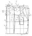
- mold of this invention The expanded view which shows the right half body part of the spine original type
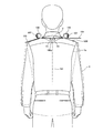
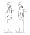
- Explanatory drawing which shows the measurement state of the length of a wearer's provisional left shoulder front and back base points N and M and the ground surface GL.
- Explanatory drawing of the base point setting measure Explanatory drawing of a height measurement measure.
- Explanatory drawing which suspended the loop-shaped base point setting measure from the wearer's neck.
- the perspective view of the measuring device of this invention The top view of the measuring device of this invention.
- Explanatory drawing of the state which uses the measuring device of this invention. Explanatory drawing of the state which uses the measuring device of this invention.
- Explanatory drawing of the state which uses the measuring device of this invention Explanatory drawing of the state which uses the measuring device of this invention.
- Explanatory drawing of the state which uses the measuring device of this invention Explanatory drawing of the state which uses the measuring device of this invention.
- Explanatory drawing which shows the measurement state of the length of the wearer's provisional left shoulder front and back base points N and M which use the measuring device of this invention, and the ground surface GL.
- Explanatory drawing which fine-tunes the position of the left shoulder back-and-front base points N and M according to the wearer's chest width and body shape of the back width. Step explanatory drawing showing the process of creating the prototype of the present invention
- This invention consists of a left half part and a right half part formed by dividing the outer jacket main body into left and right parts from the back center line of the back part, and a substantially elliptical shape formed by partially cutting the upper part of the center upper part of the left and right half parts.
- the left and right sleeve holes, the heel formed at the front edge of the left body part body, the chest width part in front of the sleeve hole part, the side width part below the sleeve hole part, and the back behind the sleeve hole part The upper part of the original centerline of the wearer's original back center line, formed by joining and sewing together the partially cut ends of the left and right cuffs and the back sewing lines of the left and right body parts.
- the present invention provides a broad-type prototype characterized by having been configured.
- the correction formula applied to the chest circumference from the back center line when specifying the left and right shoulder back base points is (0.15 to 0.20) about 1/2 of the chest circumference. It is intended to provide a prototype of the spine characterized by multiplication.
- the correction formula applied to the length around the neck from the back center line when specifying the length around the neck is (10-15) added to the length around the neck, and the total is calculated as
- the present invention provides a broad-type prototype characterized by dividing by (5-7). Further, the curved frame 100a that can be mounted and placed around the wearer's rear neck, left and right inclined plates 104 and 105 pivotally supported on the left and right ends of the curved frame 100a via the pivot 106, and the curved frame 100a are free.
- a ground height measuring device capable of measuring the length from the left and right shoulder front and rear base points (N, M) set on the end to the ground level GL, and the curved frame 100a includes a left half curved portion 101a and a right half
- the bent portion 102a is a separate body and the other bent portion 101a or 102a is a telescopic mechanism in which the base end can be freely inserted into the base end of one bent portion 101a or 102a.
- , M) are provided at the lower end of the upper half measurement measure 121 and the lower half of the upper half measurement measure 121 suspended from the back side or the chest side.
- a reflecting weight 122 that receives reflection.
- the embodiment of the spine prototype X of the present invention is basically formed by separating the outer body 100 from the wearer's original back center line 101 ′ on the back.
- the cutout end portions S of the sleeve hole 3 and the back center lines 101 of the left and right half body parts 1 and 2 are joined and sewn.
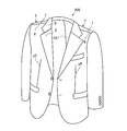
- the right and left shoulder front base point N and the right and left shoulder rear base point M are specified while correcting various measurement values on the shoulder portions of the left and right half body parts 1 and 2, and the left and right shoulder front base point N or the neck muscles.
- the line connected to the notch front end 35 of the cuff 3 from the reference point in the middle of the line is defined as the front shoulder ridge line 6, and the shoulder M from the left and right shoulder rear base point M or the reference point in the middle of the neck line
- a line connected to the notch rear end portion 36 of the sleeve hole portion 3 at an inclination angle ⁇ ′ is referred to as a rear shoulder ridge line 7.
- the three-dimensional spine prototype X (shown in FIG. 4) is completed by joining and sewing the front shoulder ridge line 6 and the back shoulder ridge line 7.
- the left and right half parts 1 and 2 are basically composed of a front body I and a back body B.
- the front body is the front body and the rear body is the back body.
- the front and back bodies a and b are cut separately and then sewn together at a predetermined line.
- the stitching line between the front body a and the back body b is “front shoulder ridge line 6 and back shoulder ridge line 7” and “sewing allowance y4”. 1 is formed.
- step S1 (1) Identification of the virtual base point M ′ behind the left shoulder (steps S1, S2)
- the virtual base point M ′ behind the left shoulder is specified (steps S1 and S2).
- the point moved outward by the length multiplied by 0.1 is defined as the back base point O ′, and 1/2 P of the chest circumference from the back base point O ′ is multiplied by (0.177 ⁇ 0.005).
- This point is specified by moving forward by the length L1 and further vertically moving from the moving point m by a length L2 that is about 1/4 of the moving length (steps S1 and S2).
- the length around the wearer's neck is not limited to the length P of the wearer's chest circumference.
- the virtual base point N ′ in front of the left shoulder is (0.56 ⁇ 0.05) times the length L3 (FD) from the front edge 4 of the front body to the side width point D of the front edge of the cuff 3 This is a point specified by the intersection of the vertical line G of the vertical point g of the position and the absolute horizontal line v from the virtual base point M ′ behind the left and right shoulders.
- the back base point O ′ is made to correspond to the above human skeleton point, and the shoulder angle is measured around this point, and the virtual base points M ′ and M ′ behind the left and right shoulders and the virtual base point N ′ before the left and right shoulders in the embodiment.
- N ', and the actual correct base points M, N are determined from various measured values and correction values described later to create the left and right half parts 1, 2, so that the wearer feels the most burden when wearing the suit It is possible to create a prototype that fits the body shape of each person who has not.
- the seventh cervical vertebra is one of seven vertebrae, which can be confirmed by a long spinous process protruding backward with a tactile sensation.
- a spinous process of the first thoracic vertebra is one of seven vertebrae, which can be confirmed by a long spinous process protruding backward with a tactile sensation.
- Below the spinous process is a spinous process of the first thoracic vertebra.
- the upper spinous process (7th cervical vertebra) moves with the movement of the neck, but the lower spinous process (1st thoracic vertebra) does not move.
- the wearer wears the back because the wearer's original back center line 101 'is the base point O' of all dimensions.
- the wearer's original back base point O ′ is determined in consideration of the clear portion.
- the length between the back upper end O and the back base point O ′ is L1 ⁇ 0.1 (1/10).
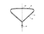
- the base point setting measure 30 is composed of a loop-like string body 31 as shown in FIG. 9, and the center-point of the loop-like string body 31 obtained by virtually dividing the loop-like string body 31 is for the base point.
- the other point obtained by interposing the weight 32 and virtually dividing the string 31 into two equal parts, that is, a point located on the opposite side of the weight 32 is set as a reference point KP.
- a display scale 33 indicating a length such as mm or cm is displayed on one side of the center, ie, the reference point KP.
- the height measuring measure 40 includes a height weight 42 connected to one end of a long string body 41, and a long string body to indicate the length from the bottom surface of the weight 42.
- Reference numeral 41 denotes a height display scale 43 indicating a length such as mm or cm.
- the height weight 42 causes the tension of the long string body 41 when measuring the length from the ground surface to the temporary left and right shoulder front and rear base points N and M, and provides an accurate length dimension. It is for acquisition and performs the same function as the falling weight used for surveying civil engineering works.
- the height measurement measure 40 is an instrument that measures the length from the ground surface (GL) to the left and right shoulder front and rear points N and M by using the tension of the long string body 41 by using the height weight 42.
- the ground height measuring device 120 using the electronic device can be used so that it can be measured more easily and accurately.
- the measurement values using the base point setting measure 30 and the height measurement measure 40 configured as described above are used as shown in FIGS. 11 and 8 and are based on “temporary left and right shoulder front and rear points N and M”. It is used to correct the position of “right and left shoulder rear base point M and left and right shoulder front base point N” to fit the wearer's body shape, and finally right and left shoulder rear base point M and left and right shoulder front base point N The pattern U at the correct position is created.
- a loop-shaped base point setting measure 30 is suspended from the wearer's neck.
- the base point weight 32 is positioned at the chest.
- This state is a state in which the loop-shaped string 31 is suspended from the neck to the chest, so to speak, the left and right lines 34, 34 of the loop-shaped string 31 trace the left and right lines of the suitcase.
- the string 31 locus is formed.
- the back base point GP of the string body 31 coincides with the position of the wearer's back base point O ′, that is, the position of the border center of the seventh cervical vertebra and the first thoracic vertebra.
- a temporary reference dimension of 9 cm is set as provisional temporary left and right shoulder rear base points M and left and right shoulder front base points N (naturally, the left and right shoulder rear base points M and the left and right shoulder front base points N are provisionally determined as one point coincident with each other) ( Step S4).
- the temporary reference dimension of 9 cm is the average standard dimension of the wearer.
- the position of the virtual base point M ′ behind the left and right shoulders is inevitably specified on the temporary pattern, and the temporary pattern is based on this.
- the length rcm of the neck line WN of the curved line between the back base point O ′ and the virtual base point M ′ behind the left and right shoulders (in other words, the left side from the reference point KP in the base point setting measure 30 suspended from the wearer's neck)
- the length to the position of the correct virtual base point M ′ that moves in the direction is calculated (step S3).
- the position of the length rcm of the neck line WN is the position of the virtual base point M ′ behind the left and right shoulders and the virtual base point N ′ before the left and right shoulders as measured by the wearer. Since the positions of the base point M ′ and the base point N ′ are calculated positions in the case of a wearer having an ideal upright and immobile standard body shape without any body or back, this base point M is determined by the peculiarity of the wearer's body shape. The work of correcting the position of ', base point N' to the right and left shoulder front and back base points N, M suitable for the wearer must be performed. This correction work will be described below.
- the position of the temporary reference dimension 9 cm in the body 31 is set as the “temporary left shoulder front and rear base points N and M”, which is set as the temporary left shoulder front and rear base points N and M in the temporary pattern U (step S4).
- the position of the virtual base point M ′ behind the left shoulder is set to (1 / 2P) of the actually measured wearer's chest circumference from the back base point O ′ as described in paragraph [0025]. 177 ⁇ 0.005) multiplied by the length L1 and further moved vertically from the moving point m by a length L2 that is about 1/4 of the moving length, or around the neck It is tentatively determined as a point determined by measurement.
- the neck line WN of the curved line is a string 31 of the base point setting measure 30 suspended from the neck.
- the position of the temporary reference dimension 9 cm of the neck line WN from the back base point O ′ is set as the position of the temporary left shoulder rear base point M on the wearer's left shoulder (step S4).
- the calculated length rcm of the neck line WN in the pattern U is an objective calculation length derived from the above measurement (calculation of paragraph number [0025]) from the actual measurement of the chest circumference of the wearer.
- this curved length rcm is a length from the back base point O ′ to the original correct left shoulder rear base point M in the loop-like string 31. It can be said that.
- the temporary left shoulder base M was initially assumed to be the position of the standard dimension 9 cm of the string 31, the position of the wearer's cooling, stoop, etc. was not taken into account. It is not the position of the original right shoulder rear base point M. Accordingly, it is necessary to determine which point of the wearer's body shape is the right and left base points N and M in consideration of the peculiarities such as the wearer's body and back.
- the wearer in order to determine the position of the original right shoulder rear base point M on the pattern U, the wearer starts from the ground surface (GL) at the position of the temporary left shoulder rear base point M set to the position of the reference dimension 9 cm of the string 31.
- the length is measured on the back side and the chest side (step S6).
- the length from the ground surface (GL) to the temporary left and right shoulder rear base point M and the temporary left and right shoulder front base point N is measured by the height measurement measure 40, and this is performed as follows. That is, the length ⁇ from the ground surface (GL) to the temporary left and right shoulder rear base point M is measured on the back side (rear side) of the wearer, and the length from the ground surface (GL) to the temporary left and right shoulder front base point N is measured. Is measured on the chest side (front side) of the wearer (step S6).
- the length ⁇ from the ground surface (GL) to the temporary left and right shoulder rear base point M and the temporary left and right shoulder front base point N are measured.
- the length ⁇ can be measured, and the structure of the ground height measuring device 120 is configured as follows.
- the length ⁇ from the ground surface (GL) to the temporary left and right shoulder rear base point M is measured along the back side (rear side) of the wearer, and the temporary left and right front base point from the ground surface (GL).
- the length ⁇ up to N is for measuring the length along the chest side (front side) of the wearer.
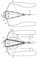
- the curved frame 100a used for measuring the inclination angle of the shoulder of the wearer described above is used. To do.
- the curved frame 100a is placed on the wearer's rear neck K, and the free end of the curved frame 100a is placed on the temporary left and right shoulder front and rear base points (N, M ) And the right and left free end positions 100a ′ of the curved frame 100a when the curved frame 100a is attached to the neck.
- 100a ′′ that is, ground height measurement using electronic equipment to measure the length ⁇ , ⁇ along the back and chest from the temporary left and right shoulder front and back base points (N, M) position to the ground surface (GL)
- An apparatus 120 can be used.
- the ground height measuring device 120 is configured by connecting the upper end of the upper half measurement measure 121 to the left and right free ends of the curved frame 100 a and providing the weight 122 with reflection function at the lower end of the measure 121.
- the upper half measurement measure 121 is made of a flexible last material so as to follow the wearer's back and chest, and the lower end of the flexible upper half measurement measure 121 is substantially in the middle of the chest side or the back side. It has a short length and is suspended downward from the temporary left and right shoulder front and rear base points (N, M).
- the reflecting function-provided weight 122 is provided with a transmitting section 124-1 for reflecting infrared rays, ultrasonic waves, and the like and a receiving section 124-2 for receiving these reflections on the lower end surface of the weight case 123. Accordingly, if the length of the upper half measurement measure 121 is set to a short length in advance, for example, set to 1 m, the measure 121 is moved from the temporary left and right shoulder reference points (N, M) to the chest and back of the wearer. It is easy to hang along the surface, and then the reflection time from the ground surface (GL) such as infrared rays transmitted from the reflection function vertical weight 122 at the lower end of the measure 121 is measured to measure the ground from the reflection function vertical weight 122.
- GL ground surface
- the distance to the upper surface (GL) will be measured, and the length obtained by adding the 1 m length of the upper half measurement measure 121 to this distance is the wearer's temporary left and right shoulder front and rear base points (N, M)
- the length ⁇ or ⁇ reaches the ground surface along the chest side or back side of the wearer. That is, the length from the temporary left and right shoulder front and rear base points (N, M) to the ground surface (GL) along the chest side and back side of the wearer is simply and easily and accurately measured by the short upper half measurement measure 121. Can be measured.
- step S7 the difference (difference between ⁇ and ⁇ ) is obtained, and the difference between ⁇ and ⁇ is used for correcting the position of the temporary left shoulder front base point M (step S7).
- this 0.5 cm difference (LX) is used as an increase / decrease factor of ⁇ and ⁇ measured at the position of the temporary left shoulder rear base point M (position of the reference dimension 9 cm of the string 31) (step S7).
- the position of the left shoulder front base point N is determined from the front body front edge 4 to the side edge D of the front edge of the cuff 3 as described in paragraph [0026].
- the ground height ( ⁇ ) of the temporary left shoulder rear base point M is corrected, and the upper part of the back body is extended upward or shortened downward due to the body shape.
- a correction is made to the ground height ( ⁇ ) of the temporary left shoulder base N, and the upper part of the front body i is expanded and contracted upward and downward by the correction amount. Therefore, for the first time, the correct left and right shoulder bases N and M are specified.
- the shoulder inclination angles ⁇ and ⁇ ′ are measured from provisional base points M and N at a preset reference dimension of 9 cm. That is, a constant adjustment angle from the left shoulder front base point N, that is, a line connected to the notch front end portion of the cuff 3 with the shoulder inclination angle ⁇ is defined as the left front shoulder ridge line 6, and a constant adjustment angle from the left shoulder rear base point M. That is, the line connecting the shoulder end angle ⁇ ′ and the notch rear end portion of the sleeve hole portion 3 is defined as the left and right rear shoulder ridge lines 7 (step S8).
- the measurement timing of the shoulder inclination angle has been described in the present embodiment at the timing of step S8 in FIG. 20, it may be measured, for example, between steps S4 and S5 in FIG. That is, the shoulder inclination angles ⁇ and ⁇ ′ may be measured after setting a point having a reference dimension of 9 cm as the temporary base points M and N.
- the front shoulder ridge line 6 with a constant inclination angle ⁇ from the left shoulder front base point N and the rear shoulder ridge line 7 with a constant inclination angle ⁇ ′ from the left shoulder rear base point M have an adjustment angle of 23 degrees in a normal standard angle. Actually, it is determined by measuring the wearer's shoulder line with a measuring instrument such as a protractor.
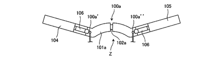
- the inventor has devised a measuring instrument Z that can be measured easily and accurately when measuring the shoulder line of the wearer with a measuring instrument such as a protractor. That is, as shown in FIGS. 12 to 14, first, a curved frame 100a that can be mounted and placed around the rear neck of the wearer is provided, and both ends 100a ′ and 100a ′′ of the curved frame 100a are temporarily specified left shoulders. Corresponding to the positions of the M and N coincidence points where the rear base point M and the left shoulder front base point N coincide with each other, and the positions of the right shoulder rear base point M and the right shoulder front base point N which are tentatively specified, respectively. Configure as follows.
- the curved frame 100a Since the positions of the left and right M and N points are displaced from side to side depending on the wearer's skeleton, shoulder width, etc., the curved frame 100a has a structure that can be expanded to the left and right. For example, the left half-curved portion 101a and the right half-curved point Separate from the portion 102a, the other bent portion 101a or 102a can be inserted into the base end of one bent portion 101a or 102a.
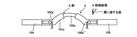
- the cross-sectional shape of the curved frame 100a can be placed around the rear neck as a slightly inclined curved surface wx as shown in the side view of part A shown in FIG. 14 so that the lower end surface can be placed around the rear neck of the wearer. Make the shape as close as possible.
- left and right inclined plates 104 and 105 for measuring the inclination angle of the shoulder ridge line are connected to the left and right ends of the curved frame 100a so as to be freely slidable. That is, the base ends of the left and right inclined plates 104 and 105 are pivotally supported via the pivot 106 at the left and right ends of the curved frame 100a. Since the left and right inclined plates 104 and 105 are pivoted about the pivot 106, the measurement scale 107 for measuring the tilt angle from the absolute horizontal position at the portion of the pivot 106 in order to measure the absolute tilt angle due to the swing. Is attached. The measurement scale 107 is provided with a horizontal leveler (not shown).
- the horizontal leveler 103 is configured to detect the absolute horizontal position, and the inclination angle is detected by converting from the absolute horizontal position.
- a digital display unit is provided in place of the measurement scale 107, and the tilt angle is determined by electrically detecting the peristalsis of the left and right inclined plates 104 and 105. It can also be configured to display on a digital display.
- a power source unit, a control unit, and a leveler mechanism are built in the curved frame 100a, and the movement of the left and right inclined plates 104 and 105 is electrically detected, and the inclination angle of the left and right inclined plates 104 and 105 is displayed. It is comprised as follows.
- the curved frame 100 a is placed on the wearer's rear neck muscle K, and the left and right shoulder rear base points M and M and the left and right shoulder front base points N are placed on the left and right ends of the frame 100 a.
- the left and right inclined plates 104 and 105 are placed on the left and right shoulder ridge lines from the positions of the left and right shoulder rear base points M and M and the left and right shoulder front base points N and N, respectively.
- the inclination angles of the left and right inclined plates 104 and 105 tilting as the center are measured by a measurement scale 107 or an electrical detection method.
- bust line B About bust line B, waist line W, hip line H, hem line J
- the left half part 1 forms bust line B, waist line W, hip line H, and hem line J at a fixed distance from the upper edge. ing.
- the vertical length of O ′ to C is the height K.
- the back base point O ′ is set at a point obtained by multiplying 1/2 P of the chest circumference by about 0.15 and about 0.1.
- a 2 cm clearance y2 is formed from the bust point C of the bust line B.
- C ′ bust clearance point
- C ′ clearance point
- y1 clearance y1 from the bust point C of the bust line B
- the lateral width of C ′ to E is the back width portion b1. From the back width point E of the rear edge position of the sleeve hole portion 3 in the bust line B to the point of the length obtained by multiplying 1/2 P of the chest circumference by about 0.25, that is, the front edge of the sleeve hole portion 3. The point is the side width point D, and the lateral width of D to E is the side width part b2.
- the button position on the front edge of the front body a of the outer body 100 is the button point F, and the width obtained by multiplying 1 / 2P of the chest circumference by about 0.37 is the horizontal width of DF.
- a point having a length obtained by multiplying the length of D to F by about 0.56 in the middle of D to F is defined as a vertical point g, and the upper end of the vertical line G of the vertical point g is the left shoulder front base point N. .
- the waist line W is an intermediate point between the bust line B and the hip line H, that is, a horizontal line of the waist point I of (B to H) ⁇ 1/2.
- the hip line H is a horizontal line at the hip Q point having a length obtained by multiplying the length from the back base point O ′ to the hem line J by about 0.184.
- y5 is a front dart which shows the clearance below a heel in the figure.
- R represents a breast pocket.
- Reference numeral 5 ′ denotes a neck collar portion that is continuously provided and stitched to the upper end portion of the collar portion 5, and is continuously stitched to the upper end portion (5 ′′) of the back width portion b 1 other than the front and rear shoulder ridge lines 6 and 7.
- the hem line J has a front hem line J1 descending about 1.5 cm, and the hem line J looks generally horizontal when worn, so that the overall appearance of the suit is good.
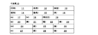
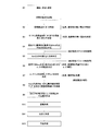
- FIG. 7 shows a dimension table 10 for entering measurement dimensions, and the following columns are provided. That is, Measurement date and time column 11, wearer's name column 12, body type column 13 describing the distinction and dimensions of the body and the body, A column 14 for entering the shoulder inclination angle from the left and right shoulder front base point N, a column 15 for entering the shoulder inclination angle from the left and right shoulder rear base point M, A column 16 for entering an average angle obtained by multiplying the sum of the tilt angle from the left and right shoulder front base point N and the tilt angle from the left and right shoulder rear base point M by 1/2; In order to specify the left and right shoulder base N, the N point dimension column 17 for entering a number obtained by multiplying the length L of (F to D) and (0.56 ⁇ 0.05), To specify the left and right shoulder rear base point M, enter the number L1 obtained by multiplying 1/2 of the chest circumference length P by (0.177
- M point dimension column 18 A height dimension column 19 for entering the length from the back base point O ′ to C located at the lower side by a length obtained by multiplying 1 / 2P of the length of the chest circumference by 0.45, Chest circumference dimension column 20 for entering a numerical value obtained by adding a margin dimension as a space to the actual chest circumference P ′, A chest width column 21 for entering the dimensions of the chest width portion b3 in the bust line B actually measured; Side width column 22 for entering the dimensions of side width part b2 in bust line B, A back width column 23 for entering the dimensions of the back width portion b1 in the bust line B; Waist dimension column 24 for entering dimensions in the waist line W, Waist width column 25 for entering the width dimension of the front body a in the waistline W, Waist rear width column 26 for entering the width dimension of the back body in the waistline W, Hip front width column 27 for entering the actual measurement in the hip line H, Front hip width column 28 for entering the width of the front body a in the hip line H, Hip
- the base point setting measure 30 is then suspended from the neck, and the position of the length rcm of the left neck line WN is taken from the reference point KP, so For non-exemplary standard body wearers this is necessarily the position of the correct left shoulder back origin M (N) in the wearer's body.
- the height measurement measure 40 measures the length of the back side and the chest side from the ground surface (GL), and ⁇ and ⁇ are calculated. put out.
- the trace t1 of the curved length of the curved neck line WN from the back base point O ′ and the actually measured scale length from the ground surface (GL) to the left shoulder rear base point M Let the intersection with the locus t2 be the correct position of the left shoulder rear base point M in the pattern U.
- the position calculation method (paragraph) of the virtual base point M' behind the left shoulder according to the inventor's many years of tailoring results
- the virtual base point M ′ behind the left shoulder is determined from the number [0025]), and the correct base point M behind the left shoulder on the wearer's original body is further added to the values of ⁇ and ⁇ measured by the base point setting measure 30.
- the position of the virtual base point M ′ after the left shoulder calculated from the chest circumference is corrected, and the correct left shoulder base point M on the pattern U is specified.
- the right and left shoulder bases N and M and the right shoulder front and rear base points N and M are determined to be optimal positions that match various body types such as the back, crouch, shoulder, and shoulder. It is possible to balance the balance between the left and right sides of the base point O ′ (swing action), and it is possible to provide a smart and comfortable suit with respect to appearance and wearer activity.
- “Yajirobee” is configured so that the center point is set and balanced by the weights on the left and right sides. Hold.
- the spine is based on the shoulder inclination angles ⁇ and ⁇ ′ from the left and right shoulder front and rear base points N and M, the back side length ⁇ and the ground surface (GL) from the ground surface (GL) to the left and right shoulder front and rear base points N and M.
- the left / right front / rear base points N and M have the same left / right balance function as “Yajirobe” centered on the back base point O ′ when the length ⁇ on the chest side matches the body shape of the suit wearer. And it becomes a suit that fits the wearer most in terms of appearance and comfort (steps S11 and S12).
- the front body and the back part of the body must be It should be noted that the width of the is different from that of a standard size wearer.
- the positions of the left and right shoulder front and rear base points N and M are finely adjusted according to the wearer's chest width and back width body shape. If N and M are moved in parallel, vertical movement occurs in the front body i and back body b. That is, new left and right shoulder front and rear base points N-1 and M-1 obtained by finely adjusting the left and right shoulder front and rear base points N and M by parallel translation by the length of ⁇ (for example, 5 mm) in the dimensional diagram of the pattern shown in FIG. A pattern is created by collecting various dimensions as reference points.
- the area of the front body i will be increased accordingly and Exercise occurs.
- the left and right shoulder rear base point M is moved 5 mm to the right as shown in FIG. 19 to be a new left and right shoulder rear base point M-1
- the area of the rear body B will be increased accordingly, and upward movement will occur in the front body i.
- the left and right shoulder front base point N is moved 5 mm to the right as shown in FIG. 19 to be a new left and right shoulder front base point N-1
- the area of the front body a becomes narrower and the downward movement occurs in the front body a.
- left and right shoulder rear base point M is moved 5 mm to the left as shown in FIG. 19 to be a new left and right shoulder rear base point M-1, the area of the back body will be reduced accordingly, and downward movement will occur in the back body .
- the left and right shoulder front and back base points N and M are finely adjusted by moving by the length of ⁇ , and the chest width and back width are adjusted by using the new left and right shoulder front and rear base points N-1 and M-1 as reference points.
- an important back base point O ′ can be determined by “sagging” (swinging action), and a comfortable suit that fits the body shape can be provided.
- This "Yajirobe” (swing action) occurs not only on the left and right sides of the shoulder but also on the front and rear of the shoulder.
- the swing is centered on the back base point O 'in the lateral and lateral directions and the front and rear direction around the shoulder. Since the spine prototype is tailored in the state of action, it is possible to provide a comfortable suit that fits the wearer's body shape.
Landscapes
- Engineering & Computer Science (AREA)
- Textile Engineering (AREA)
- Life Sciences & Earth Sciences (AREA)
- Biophysics (AREA)
- Corsets Or Brassieres (AREA)
Abstract
Priority Applications (4)
| Application Number | Priority Date | Filing Date | Title |
|---|---|---|---|
| PCT/JP2015/067092 WO2016199308A1 (fr) | 2015-06-12 | 2015-06-12 | Modèle de costume motif et dispositif de mesure pour modèle de costume |
| CN201580080869.4A CN107846992A (zh) | 2015-06-12 | 2015-06-12 | 西装原型以及西装原型用测定器 |
| US15/580,958 US10524520B2 (en) | 2015-06-12 | 2015-06-12 | Suit pattern and measuring device for suit pattern |
| KR1020177035720A KR101992721B1 (ko) | 2015-06-12 | 2015-06-12 | 신사복 원형의 제작방법 |
Applications Claiming Priority (1)
| Application Number | Priority Date | Filing Date | Title |
|---|---|---|---|
| PCT/JP2015/067092 WO2016199308A1 (fr) | 2015-06-12 | 2015-06-12 | Modèle de costume motif et dispositif de mesure pour modèle de costume |
Publications (1)
| Publication Number | Publication Date |
|---|---|
| WO2016199308A1 true WO2016199308A1 (fr) | 2016-12-15 |
Family
ID=57504599
Family Applications (1)
| Application Number | Title | Priority Date | Filing Date |
|---|---|---|---|
| PCT/JP2015/067092 Ceased WO2016199308A1 (fr) | 2015-06-12 | 2015-06-12 | Modèle de costume motif et dispositif de mesure pour modèle de costume |
Country Status (4)
| Country | Link |
|---|---|
| US (1) | US10524520B2 (fr) |
| KR (1) | KR101992721B1 (fr) |
| CN (1) | CN107846992A (fr) |
| WO (1) | WO2016199308A1 (fr) |
Cited By (2)
| Publication number | Priority date | Publication date | Assignee | Title |
|---|---|---|---|---|
| CN107080300A (zh) * | 2017-06-12 | 2017-08-22 | 苏州凤霓绣叶文化艺术有限公司 | 一种节省衣料的旗袍制作方法 |
| CN113966884A (zh) * | 2021-10-28 | 2022-01-25 | 绍兴市博亚服饰有限公司 | 前冲肩特体处理方法 |
Families Citing this family (2)
| Publication number | Priority date | Publication date | Assignee | Title |
|---|---|---|---|---|
| CN109123825B (zh) * | 2018-07-27 | 2021-05-28 | 浙江乔治白服饰股份有限公司 | 一种冲肩体型服装处理方法 |
| CN110274919A (zh) * | 2019-07-10 | 2019-09-24 | 天津工业大学 | 基于Faster R-CNN的裁片花纹参数测量方法 |
Citations (6)
| Publication number | Priority date | Publication date | Assignee | Title |
|---|---|---|---|---|
| JPS5387839A (en) * | 1977-01-11 | 1978-08-02 | Fujii Keori Kk | Auxiliary aid for clothes |
| JPS59157303A (ja) * | 1983-02-22 | 1984-09-06 | 中嶋 達治 | 背広形上衣の製造法 |
| JPH0166004U (fr) * | 1987-10-22 | 1989-04-27 | ||
| JPH0429606U (fr) * | 1990-07-05 | 1992-03-10 | ||
| JP2000265313A (ja) * | 1999-03-12 | 2000-09-26 | Tetsuo Mabuchi | 上着用型紙の作成方法 |
| WO2013190686A1 (fr) * | 2012-06-21 | 2013-12-27 | FUNABASHI Yukihiko | Patron de costume |
Family Cites Families (30)
| Publication number | Priority date | Publication date | Assignee | Title |
|---|---|---|---|---|
| US3745656A (en) * | 1971-05-10 | 1973-07-17 | Warren C Huff | Garment pattern making device and method |
| US3815154A (en) * | 1972-12-07 | 1974-06-11 | G Gearhart | Method of and means for improving the armhole construction of a garment |
| US3979831A (en) * | 1974-11-22 | 1976-09-14 | Lutz Helene P | Method and apparatus for altering clothing patterns |
| ZA771434B (en) * | 1977-03-09 | 1978-10-25 | F Werber | Method of and apparatus for garment patterning |
| US4224740A (en) * | 1978-06-08 | 1980-09-30 | Gibson Donald A | Pants suit pattern |
| HUT60607A (en) * | 1986-08-19 | 1992-10-28 | Horst Forschner | Method for producing wearing apparels carrying out by the user and set for producing such wearing apparels |
| JPS63126905A (ja) * | 1986-11-13 | 1988-05-30 | 伊藤 満 | 上衣 |
| US4885844A (en) * | 1988-11-14 | 1989-12-12 | Chun Joong H | Computer aided custom tailoring with disposable measurement clothing |
| US5060393A (en) * | 1991-03-11 | 1991-10-29 | Pin Dot Products | Apparatus for taking body measurements |
| US6073359A (en) * | 1998-03-25 | 2000-06-13 | Lee; In Bok | Height measuring device |
| US6226881B1 (en) * | 1999-08-12 | 2001-05-08 | Clover Global Group, Inc. | Height-measuring device |
| JP4537553B2 (ja) | 2000-09-01 | 2010-09-01 | 株式会社ゴールドウインテクニカルセンター | 上着 |
| US7263726B2 (en) * | 2002-04-19 | 2007-09-04 | Moshe Gadot | Jacket suitable for machine washing and tumble drying |
| US6957497B2 (en) * | 2004-01-13 | 2005-10-25 | Foot Levelers, Inc. | Method and apparatus for taking measurements for a custom pillow |
| US7249423B2 (en) * | 2005-05-27 | 2007-07-31 | Westmark International, Inc. | Measuring device for garment tailoring, and related methods |
| US8001617B2 (en) * | 2005-09-15 | 2011-08-23 | Cristi Turney | Green means 4 kids attire |
| JP4779085B2 (ja) | 2009-05-29 | 2011-09-21 | 株式会社フェニックス | 衣服、その上パターンおよび下パターン |
| CN101904586A (zh) * | 2009-06-02 | 2010-12-08 | 刘箭 | 适合肥胖体形西服的裁剪方法 |
| CN201504574U (zh) * | 2009-10-21 | 2010-06-16 | 北京威克多制衣中心 | X造型西服 |
| US8528221B2 (en) * | 2010-10-21 | 2013-09-10 | Russell Glock, JR. | Family height recording device |
| US8549763B2 (en) * | 2010-12-15 | 2013-10-08 | Tamara KRAWCHUK | System and method for garment fitting and fabrication |
| EP2581701B1 (fr) * | 2011-10-11 | 2013-05-29 | King Saud University | Appareil pour déterminer une dimension d'une surface donnée d'un objet |
| CN103705081A (zh) * | 2012-09-29 | 2014-04-09 | 米振宇 | 防变形衣架 |
| GB2508183A (en) * | 2012-11-22 | 2014-05-28 | Burberry Ltd | Garments comprising multiple layers |
| US9389056B2 (en) * | 2013-01-21 | 2016-07-12 | James L. Wood | Height measurement system |
| CN104273674A (zh) * | 2013-07-12 | 2015-01-14 | 山东科技职业学院 | 一种无归拔、无垫肩、无胸衬、超轻超薄时尚西装版型 |
| WO2015042372A1 (fr) * | 2013-09-19 | 2015-03-26 | Fenimore Ryan Devin | T-shirt pour prise de mesure |
| CN104207394B (zh) * | 2014-08-22 | 2016-02-10 | 老合兴洋服(杭州)有限公司 | 服装高级定制的试样方法 |
| JP2019044286A (ja) * | 2017-08-31 | 2019-03-22 | 株式会社バーンズファクトリー | テーラードジャケット、およびその製造方法 |
| US20190174842A1 (en) * | 2017-12-12 | 2019-06-13 | Lawrence Kalkstein | Jacket, tie and shirt combination |
-
2015
- 2015-06-12 WO PCT/JP2015/067092 patent/WO2016199308A1/fr not_active Ceased
- 2015-06-12 US US15/580,958 patent/US10524520B2/en not_active Expired - Fee Related
- 2015-06-12 KR KR1020177035720A patent/KR101992721B1/ko not_active Expired - Fee Related
- 2015-06-12 CN CN201580080869.4A patent/CN107846992A/zh active Pending
Patent Citations (6)
| Publication number | Priority date | Publication date | Assignee | Title |
|---|---|---|---|---|
| JPS5387839A (en) * | 1977-01-11 | 1978-08-02 | Fujii Keori Kk | Auxiliary aid for clothes |
| JPS59157303A (ja) * | 1983-02-22 | 1984-09-06 | 中嶋 達治 | 背広形上衣の製造法 |
| JPH0166004U (fr) * | 1987-10-22 | 1989-04-27 | ||
| JPH0429606U (fr) * | 1990-07-05 | 1992-03-10 | ||
| JP2000265313A (ja) * | 1999-03-12 | 2000-09-26 | Tetsuo Mabuchi | 上着用型紙の作成方法 |
| WO2013190686A1 (fr) * | 2012-06-21 | 2013-12-27 | FUNABASHI Yukihiko | Patron de costume |
Cited By (2)
| Publication number | Priority date | Publication date | Assignee | Title |
|---|---|---|---|---|
| CN107080300A (zh) * | 2017-06-12 | 2017-08-22 | 苏州凤霓绣叶文化艺术有限公司 | 一种节省衣料的旗袍制作方法 |
| CN113966884A (zh) * | 2021-10-28 | 2022-01-25 | 绍兴市博亚服饰有限公司 | 前冲肩特体处理方法 |
Also Published As
| Publication number | Publication date |
|---|---|
| CN107846992A (zh) | 2018-03-27 |
| KR101992721B1 (ko) | 2019-06-25 |
| US20180177246A1 (en) | 2018-06-28 |
| US10524520B2 (en) | 2020-01-07 |
| KR20180004809A (ko) | 2018-01-12 |
Similar Documents
| Publication | Publication Date | Title |
|---|---|---|
| EP2849594B1 (fr) | Procédé de dessin de patrons de vêtement à partir de photographies et de dessins de style | |
| Gupta | Anthropometry and the design and production of apparel: an overview | |
| JP5704675B2 (ja) | 背広原型 | |
| US20030011590A1 (en) | Method for three-dimensional digital designing of garment | |
| US9456647B2 (en) | System and method for drafting garment patterns | |
| US6978549B2 (en) | Patterning system for a selected body type and methods of measuring for a selected body type | |
| Beazley | Size and fit: procedures in undertaking a survey of body measurements | |
| US12178271B2 (en) | Patterning system for selected body types and articles of manufacture produced therefrom | |
| JP2004501432A (ja) | 3次元デジタルによる衣服設計方法 | |
| WO2016199308A1 (fr) | Modèle de costume motif et dispositif de mesure pour modèle de costume | |
| JP6424348B2 (ja) | 背広原型の作成方法 | |
| WO2016032943A1 (fr) | Système et procédé destinés à tracer des patrons de vêtements | |
| Kim et al. | Patternmaking for menswear: classic to contemporary | |
| JP3671401B2 (ja) | 計測器及び原型作図法 | |
| Ahmed et al. | The suitability of body scanning measurement in pattern drafting methods | |
| JP2004027462A5 (fr) | ||
| Roy | The Tailor’s Voice: Pattern Drafting Systems and the State of the Art | |
| JP2000265313A (ja) | 上着用型紙の作成方法 | |
| RU2187233C1 (ru) | Способ построения основы плечевого изделия на конкретную фигуру с рукавами или без рукавов | |
| Li et al. | A novel method for making a one-piece tight-fitting garment | |
| Aluculesei et al. | Digital methods in developing textile products for people with locomotor disabilities | |
| HK1251966A1 (zh) | 西装原型以及西装原型用测定器 | |
| Veblen | The complete photo guide to perfect fitting | |
| Ranade et al. | Advancing adaptive clothing design for females with down syndrome: The role of body scanners and AI software | |
| RU2311861C2 (ru) | Способ построения шаблона комбинезона мужского |
Legal Events
| Date | Code | Title | Description |
|---|---|---|---|
| 121 | Ep: the epo has been informed by wipo that ep was designated in this application |
Ref document number: 15894993 Country of ref document: EP Kind code of ref document: A1 |
|
| WWE | Wipo information: entry into national phase |
Ref document number: 15580958 Country of ref document: US |
|
| ENP | Entry into the national phase |
Ref document number: 20177035720 Country of ref document: KR Kind code of ref document: A |
|
| NENP | Non-entry into the national phase |
Ref country code: DE |
|
| NENP | Non-entry into the national phase |
Ref country code: JP |
|
| 122 | Ep: pct application non-entry in european phase |
Ref document number: 15894993 Country of ref document: EP Kind code of ref document: A1 |