WO2016199445A1 - 太陽光発電システムの検査方法および検査装置 - Google Patents
太陽光発電システムの検査方法および検査装置 Download PDFInfo
- Publication number
- WO2016199445A1 WO2016199445A1 PCT/JP2016/053183 JP2016053183W WO2016199445A1 WO 2016199445 A1 WO2016199445 A1 WO 2016199445A1 JP 2016053183 W JP2016053183 W JP 2016053183W WO 2016199445 A1 WO2016199445 A1 WO 2016199445A1
- Authority
- WO
- WIPO (PCT)
- Prior art keywords
- solar cell
- inspection
- cell string
- unit
- power generation
- Prior art date
- Legal status (The legal status is an assumption and is not a legal conclusion. Google has not performed a legal analysis and makes no representation as to the accuracy of the status listed.)
- Ceased
Links
Images


Classifications
-
- H—ELECTRICITY
- H02—GENERATION; CONVERSION OR DISTRIBUTION OF ELECTRIC POWER
- H02S—GENERATION OF ELECTRIC POWER BY CONVERSION OF INFRARED RADIATION, VISIBLE LIGHT OR ULTRAVIOLET LIGHT, e.g. USING PHOTOVOLTAIC [PV] MODULES
- H02S50/00—Monitoring or testing of PV systems, e.g. load balancing or fault identification
- H02S50/10—Testing of PV devices, e.g. of PV modules or single PV cells
-
- H—ELECTRICITY
- H02—GENERATION; CONVERSION OR DISTRIBUTION OF ELECTRIC POWER
- H02H—EMERGENCY PROTECTIVE CIRCUIT ARRANGEMENTS
- H02H7/00—Emergency protective circuit arrangements specially adapted for specific types of electric machines or apparatus or for sectionalised protection of cable or line systems, and effecting automatic switching in the event of an undesired change from normal working conditions
- H02H7/20—Emergency protective circuit arrangements specially adapted for specific types of electric machines or apparatus or for sectionalised protection of cable or line systems, and effecting automatic switching in the event of an undesired change from normal working conditions for electronic equipment
-
- H—ELECTRICITY
- H02—GENERATION; CONVERSION OR DISTRIBUTION OF ELECTRIC POWER
- H02S—GENERATION OF ELECTRIC POWER BY CONVERSION OF INFRARED RADIATION, VISIBLE LIGHT OR ULTRAVIOLET LIGHT, e.g. USING PHOTOVOLTAIC [PV] MODULES
- H02S50/00—Monitoring or testing of PV systems, e.g. load balancing or fault identification
-
- Y—GENERAL TAGGING OF NEW TECHNOLOGICAL DEVELOPMENTS; GENERAL TAGGING OF CROSS-SECTIONAL TECHNOLOGIES SPANNING OVER SEVERAL SECTIONS OF THE IPC; TECHNICAL SUBJECTS COVERED BY FORMER USPC CROSS-REFERENCE ART COLLECTIONS [XRACs] AND DIGESTS
- Y02—TECHNOLOGIES OR APPLICATIONS FOR MITIGATION OR ADAPTATION AGAINST CLIMATE CHANGE
- Y02E—REDUCTION OF GREENHOUSE GAS [GHG] EMISSIONS, RELATED TO ENERGY GENERATION, TRANSMISSION OR DISTRIBUTION
- Y02E10/00—Energy generation through renewable energy sources
- Y02E10/50—Photovoltaic [PV] energy
Definitions
- the present invention relates to an inspection method and an inspection apparatus for a solar power generation system that inspects a plurality of solar cell strings included in the solar power generation system.
- the solar power generation system includes a plurality of solar cell strings, and each solar cell string is configured by connecting a plurality of solar cell modules in series.
- the DC power generated by each solar cell string is converted to AC power by the power conditioner and supplied to the commercial power system.
- Patent Document 1 describes a ground fault detection device that inspects the presence or absence of a ground fault in a solar cell string in a solar power generation system including a plurality of solar cell strings.
- the solar cell string to be inspected is disconnected from the solar power generation system, that is, the solar cell string and the power conditioner are connected by a switch unit provided between the solar cell string and the power conditioner. In the state where is electrically disconnected, the presence or absence of a ground fault of the solar cell string is inspected.
- JP 2012-119382 A (published on June 21, 2012)
- Such a problem is not limited to a ground fault inspection apparatus, but is a common problem in other inspection apparatuses that separate and inspect a solar cell string in a normal power generation state from a power conditioner.
- an object of the present invention is to provide an inspection method and an inspection apparatus for a photovoltaic power generation system that can use a low-cost switch as a switch for disconnecting a solar cell string from a power conditioner and can have a low-cost configuration. .
- an inspection apparatus for a solar power generation system is an inspection apparatus for a solar power generation system that inspects a plurality of solar battery strings connected to a power conversion apparatus.
- a voltage measuring unit that measures an output voltage
- a first switching unit that is switched in step, a determination unit that determines that the switchable state is satisfied when the output voltage of the solar cell string satisfies at least a condition of a first threshold value or less, and the solar cell string is in the switchable state.
- a control unit that controls the first switching unit to switch to the inspection unit side.
- a small and inexpensive switch for example, a relay
- the inspection device can be configured to be small and low cost.
- FIG. 2 is a circuit diagram showing a state in a case where an interelectrode voltage Va-Vb is obtained in the photovoltaic power generation system shown in FIG.
- FIG. 2 is a circuit diagram illustrating a state in a case where a first voltage is obtained in the photovoltaic power generation system illustrated in FIG. 1.
- FIG. 2 is a circuit diagram showing the state in the case of calculating
- FIG. 2 is a circuit diagram showing a state where a solar cell string to be inspected is switched in the solar power generation system shown in FIG. 1.
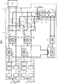
- FIG. 1 is a circuit diagram illustrating a configuration of a photovoltaic power generation system including the inspection apparatus according to the present embodiment.
- the photovoltaic power generation system 1 includes a plurality of solar cell strings 11, a ground fault detection device (inspection device) 12, and a power conditioning system (hereinafter referred to as PCS) 13 as a power conversion device.
- PCS power conditioning system
- FIG. 1 shows a state where the power generated by the solar cell string 11 is supplied to the PCS 13 and the ground fault detection device 12 is not operating (power output state).
- the solar cell string 11 is configured by connecting a plurality of solar cell modules 21 such as 10 to 20 in series.
- Each solar cell module 21 includes a plurality of solar cells (not shown) connected in series, and is formed in a panel shape.
- the ground fault resistance 22 is a resistance between the current path of the solar cell string 11 and the ground.
- Each solar cell string 11 is connected to the PCS 13 by power conducting paths 23a and 23b.
- the power supply paths 23 a and 23 b are provided for each solar cell string 11.
- the ground fault detection device 12 obtains an insulation resistance value between the solar cell string 11 and the ground point, and determines that a ground fault has occurred when the obtained insulation resistance value is smaller than a reference resistance value.
- the ground fault detection device 12 includes a power conduction path switch (first switching unit) 31, a PV switching switch (second switching unit) 32, a ground fault current detection circuit (inspection unit) 33, and a PV current detection unit. (Current measurement unit) 34, PV voltage detection unit (voltage measurement unit) 35, control unit (determination unit) 36, inspection first and second current paths (current paths) 37a, 37b, ground current path 38, and voltage detection unit 39 is provided.
- the power energization path changeover switch 31 is provided in the power energization paths 23a and 23b corresponding to each solar cell string 11, and switches the connection of the solar cell string 11 between the PCS 13 side and the ground fault current detection circuit 33 side. Specifically, the connection of the power conduction paths 23a and 23b, which are power output lines from the solar cell string 11, is switched between the PCS 13 side and the inspection first and second conduction paths 37a and 37b side.
- the inspection first and second energization paths 37 a and 37 b are provided corresponding to each solar cell string 11, and connect the power energization path switch 31 and the ground fault current detection circuit 33.
- PV changeover switch 32 is provided in inspection 1st and 2nd energization ways 37a and 37b corresponding to each solar cell string 11, and opens and closes inspection 1st and 2nd energization ways 37a and 37b.
- the ground fault current detection circuit 33 detects a ground fault current generated when a ground fault occurs in the solar cell string 11.
- the ground fault current detection circuit 33 includes an inspection first changeover switch 41, an inspection second changeover switch 42, an inspection third energization path 43, an inspection resistor R1, and voltage dividing resistors R2 to R5 that are protective resistors. Yes.
- the inspection first changeover switch 41 is connected to one end of the inspection third energization path 43, and the connection of one end of the inspection third energization path 43 is connected to the inspection first changeover switch 41. It switches between 37a and the earthing
- the inspection second changeover switch 42 is connected to the other end of the inspection third energization path 43, and the connection of the other end of the inspection third energization path 43 is connected to the inspection first changeover switch 41. Switching between the energization path 37b and the grounded energization path 38 that is grounded is performed.
- the inspection third energizing path 43 is provided with a detection resistor R1 and voltage dividing resistors R2 to R5 in series.
- the voltage dividing resistors R2 to R3 are provided between the detection resistor R1 and the inspection first changeover switch 41, and the voltage dividing resistors R4 to R5 are provided between the detection resistor R1 and the inspection second changeover switch 42. Yes.
- the voltage across the detection resistor R1 is input to the control unit 36 via the voltage detection unit 39.
- the number of voltage dividing resistors is four, but may be two. However, the risk of an accident due to a short circuit failure can be reduced by using a large number of voltage dividing resistors.
- the voltage dividing resistors R2 to R5 lower the first and second voltages V1 and V2 generated at both ends of the detection resistor R1, thereby reducing the voltage input to the control unit 36.
- the control unit 36 can be configured by a microcomputer, and the ground fault detection device 12 can be miniaturized.
- the voltage dividing resistors R2 to R5 exist in any of a circuit for obtaining the interelectrode voltage Va-Vb, a circuit for obtaining the first voltage V1, and a circuit for obtaining the second voltage V2. .
- Each PV current detection unit 34 is provided in, for example, the power energizing path 23a corresponding to each solar cell string 11, and detects and detects the amount of current flowing through the power energizing path 23a, that is, the amount of current flowing from the solar cell string 11 to the PCS 13. The result is output to the control unit 36.
- the PV voltage detection unit 35 detects the interelectrode voltage Va-Vb (voltage between PN terminals) of the solar cell string 11 and outputs the detection result to the control unit 36.
- the voltage detection unit 39 detects the voltage across the detection resistor R1 in the ground fault current detection circuit 33 and outputs the detection result to the control unit 36.
- the control unit 36 determines the power generation current of the solar cell string 11 detected by the PV current detection unit 34 and the power generation voltage (interelectrode voltage Va ⁇ Vb) of the solar cell string 11 detected by the PV voltage detection unit 35. Monitoring is performed to determine whether or not the solar cell string 11 is in a switchable state. In addition, the control unit 36 controls the switching operation of the power conduction path switch 31, the PV switch 32, the test first switch 41 and the test second switch 42, and a ground fault occurs in the solar cell string 11. The ground fault resistance and the ground fault position are obtained.
- the control unit 36 includes a storage unit 40 that stores various information such as a detection result of the presence or absence of a ground fault of the solar cell string 11 and a ground fault position when a ground fault occurs.
- a ground fault detection device is mentioned as an example of the inspection unit, but there is no problem even if it is a failure detection device for solar cells other than the ground fault.
- An example of a failure other than a ground fault is a broken circuit.
- FIG. 2 is a flowchart showing the operation of the ground fault detection device 12.
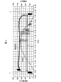
- FIG. 3 is a graph showing changes in the open circuit voltage and the amount of power generation in the solar cell string 11 on the day when the solar power generation system 1 is inspected by the ground fault detection device 12.
- the ground fault detection device 12 inspects the solar cell string 11 for a ground fault when the solar cell string 11 is in a switchable state.
- the switchable state is a state where the power generation amount (output current) of the solar cell string 11 is sufficiently small (for example, the output current of the solar cell string 11 is equal to the standby current of the PCS 13). The same level or a state smaller than the standby current of the PCS 13) (P part).
- the power generation amount (output current) is sufficiently small (for example, the output current of the solar cell string 11 is equal to the standby current of the PCS 13).
- the same level or smaller than the standby current of the PCS 13) Q section). Part P occurs early in the morning and part Q occurs in the evening.
- a range A indicates the operation time of the PCS 13.
- a condition that the output voltage (open voltage) of the solar cell string 11 is larger than zero may be added. By doing so, it is possible to perform an inspection using the generated current of the solar cell string 11.
- the above switchable state satisfies at least the condition that the output voltage of the solar cell string 11 is equal to or lower than the first threshold (for example, equal to or lower than the upper limit value of the specified output voltage in the normal power generation state of the solar cell string 11). Yes.
- the switchable state may further include a condition that the output voltage of the solar cell string 11 is greater than zero.
- the first threshold value may be, for example, 1 ⁇ 2 of the average value of the output voltage of the solar cell string 11 during the operation time of the PCS 13.
- the switchable state is, for example, a state where the value of the output voltage of the solar cell string 11 is equal to or less than the threshold value set to a value larger than zero and smaller than the average value of the output voltage during the operation time of the PCS 13. Also good.
- the state in which the output current of the solar cell string abnormally increases due to some failure can be excluded from the switchable state, and the output current of the solar cell string 11 is normal in the solar cell string 11.
- a condition of a second threshold value or less indicating that the state is present may be included.
- the switchable state may satisfy the condition that the value of the output current of the solar cell string 11 is equal to or less than the threshold value set to a value smaller than the average value of the output current during the operation time of the PCS 13.
- the second threshold value may be, for example, 1 ⁇ 2 of the average value of the output current of the solar cell string 11 during the operation time of the PCS 13.
- the power energization path switch 31 corresponding to each solar cell string 11 is switched to the PCS 13 side, and the PV switch 32 is off. (S11).
- the control unit 36 of the ground fault detection device 12 monitors the output voltage and the output current of the solar cell string 11 based on the detection results of the PV current detection unit 34 and the PV voltage detection unit 35 (S12), and thereby the solar cell. It is determined whether the string 11 is in a switchable state (S13).
- the control unit 36 sets all the power conduction path switching switches 31 from the PCS 13 side to the ground fault current detection circuit 33 side. (S14). As a result, all the solar cell strings 11 are disconnected from the PCS 13 by the switching operation of the power conduction path switch 31.
- the control unit 36 performs this control on the power supply path switching switch 31 when, for example, at least one solar cell string 11 is in a switchable state. That is, for each solar cell string 11, there may be a slight time difference in rising to the switchable state due to a subtle difference in the arrangement angle of the solar cell modules, the arrangement position, or the like. Note that the output current of the solar cell string 11 rises later than the output voltage.
- control unit 36 turns on the PV selector switch 32 corresponding to the solar cell string 11 to be inspected (S15, see FIG. 4).
- the solar cell string 11 corresponding to the PV change-over switch 32 that is turned on is connected to the ground fault current detection circuit 33 via the first and second conducting paths 37a and 37b, and the presence or absence of the ground fault is inspected. Is done.
- the PV switch 32 can be easily turned on and off. It can be carried out.
- the solar cell string 11 to be inspected in S15 is any one of the solar cell strings 11 selected in a predetermined order.
- the predetermined order may be, for example, the order of the solar cell strings 11 in a switchable state.
- the solar cell string 11 to be inspected is inspected for the occurrence of a ground fault, and when a ground fault has occurred, a ground fault position is further detected (S16).
- the control unit 36 determines that the inspection is possible when the condition that the output voltage of the solar cell string 11 is greater than zero is satisfied, turns on the PV changeover switch 32 corresponding to the solar cell string 11 to be inspected,
- the ground fault current detection circuit 33 may inspect the solar cell string 11 to be inspected for the presence of a ground fault.
- the control unit 36 inspects the management device (not shown) of the photovoltaic power generation system 1. That the ground fault has occurred about the solar cell string 11 and the position of the ground fault are notified (S18). Information such as the presence / absence of a ground fault and the position of the ground fault is stored in the storage unit 40.
- control unit 36 turns off the PV changeover switch 32 corresponding to the solar cell string 11 to be inspected (S19), and proceeds to the operation of S21.
- control unit 36 determines whether or not the inspection for all the solar cell strings 11 is completed (S21), and performs the operation of S22 if the inspection is completed. On the other hand, if the inspection is not completed, the process returns to S15 and the operations after S15 are repeated. That is, as shown in FIG. 7, the control unit 36 turns on the PV changeover switch 32 corresponding to the next solar cell string 11 to be inspected. In the same manner, the presence or absence of a ground fault of the solar cell string 11 is inspected in the same manner.
- the grounded solar cell string 11 is connected to the PCS 13 (S21), and the ground fault tested solar cell string 11 is transferred to the PCS 13. Electric power can be supplied. As a result, even if the inspected solar cell string 11 has some trouble (failure that is repaired but not urgent), the power generation function of the solar cell string 11 can be used effectively. However, instead of the above-described operation, only the solar cell string 11 having no abnormality (no ground fault) as a result of the ground fault inspection may be connected to the PCS 13.
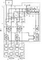
- FIG. 4 is a circuit diagram showing a state in the case where the interelectrode voltage Va-Vb is obtained in the photovoltaic power generation system 1 shown in FIG.
- FIG. 5 is a circuit diagram showing a state when the first voltage V1 is obtained in the photovoltaic power generation system 1 shown in FIG.
- FIG. 6 is a circuit diagram showing a state when the second voltage V2 is obtained in the photovoltaic power generation system 1 shown in FIG.
- the control unit 36 connects the inspection first changeover switch 41 to one end of the inspection third energization path 43 with the inspection first energization path 37a as shown in FIG.
- the second changeover switch 42 is switched so that the other end of the inspection third energization path 43 is connected to the inspection second energization path 37b.
- both positive and negative poles of the solar cell string 11 are connected via the detection resistor R1 and the voltage dividing resistors R2 to R5.
- a voltage corresponding to the resistance value of the detection resistor R1 when the voltage between the positive and negative of the solar cell string 11 is divided by the detection resistor R1 and the voltage dividing resistors R2 to R5 is generated at both ends of the detection resistor R1.
- This voltage is taken into the control unit 36 via the voltage detection unit 39, and the control unit 36 obtains the interelectrode voltage Va-Vb.
- the control part 36 connects the test
- the inspection second changeover switch 42 is switched so that the other end of the inspection third energization path 43 is connected to the ground energization path 38.
- the positive electrode (P terminal) of the solar cell string 11 is grounded via the detection resistor R1 and the voltage dividing resistors R2 to R5.
- both ends of the detection resistor R1 correspond to the resistance value of the detection resistor R1 when the voltage between the positive electrode of the solar cell string 11 and the ground potential is divided by the detection resistor R1 and the voltage dividing resistors R2 to R5.
- the first voltage V1 is generated.
- the first voltage V1 is taken into the control unit 36 via the voltage detection unit 39, and the control unit 36 obtains the first voltage V1.
- the control unit 36 connects the inspection first changeover switch 41 so that one end of the inspection third energization path 43 is connected to the ground energization path 38, as shown in FIG.
- the inspection second switching switch 42 is switched so that the other end of the inspection third energization path 43 is connected to the inspection second energization path 37b.
- the negative electrode (N terminal) of the solar cell string 11 is grounded via the detection resistor R1 and the voltage dividing resistors R2 to R5.
- both ends of the detection resistor R1 correspond to the resistance value of the detection resistor R1 when the voltage between the negative electrode of the solar cell string 11 and the ground potential is divided by the detection resistor R1 and the voltage dividing resistors R2 to R5.
- a second voltage V2 is generated.
- the second voltage V2 is taken into the control unit 36 via the voltage detection unit 39, and the control unit 36 obtains the second voltage V2. Note that the order of obtaining the interelectrode voltage Va-Vb, the first voltage V1, and the second voltage V2 is in no particular order.
- the control unit 36 compares the resistance value Rleake (insulation resistance) with a reference resistance value (threshold value), and determines that a ground fault has occurred when the resistance value Rleake is smaller than the reference resistance value.
- the control unit 36 obtains a ground fault occurrence position (ground fault position) from the ratio of the absolute values of the first and second voltages V1, V2.
- the solar cell string 11 is obtained by connecting five solar cell modules 21 in series, and the ground fault is the fourth solar cell module 21 and the fourth solar cell module 21 when viewed from the P terminal side of the solar cell string 11.
- Reference numeral 22 represents a ground fault resistance at the ground fault position.
- the ratio between the absolute value of the first voltage V1 and the absolute value of the second voltage V2 is
- 3: 2
- the ground fault position can be obtained from this ratio.
- the ground fault detection device 12 switches all the power energization path switch 31 from, for example, the PCS 13 side to the ground fault current detection circuit 33 side all at once. After that, each solar cell string 11 is sequentially inspected for the occurrence of a ground fault.
- the switchable state satisfies at least the condition that the output voltage of the solar cell string 11 is equal to or lower than the first threshold (for example, equal to or lower than the upper limit value of the specified output voltage in the normal power generation state of the solar cell string 11).
- the switchable state satisfies the condition that the output current of the solar cell string 11 is equal to or lower than a second threshold value indicating that the solar cell string is in a normal state.
- the conditions that the value of the output current of the solar cell string 11 is below the 2nd threshold value set to the value smaller than the average value of the output current in the operation time of PCS13 are satisfy
- a small and inexpensive relay with low power resistance can be used for the power energization path changeover switch 31 of the ground fault detection device 12, and the ground fault detection device 12 can be configured to be small and low cost. it can.
- the ground fault current detection circuit 33 sequentially inspects the plurality of solar cell strings 11, it takes a long time to complete the inspection of all the solar cell strings 11, the amount of sunlight increases, and the solar cell string It is conceivable that the output voltage and output current of 11 rise beyond the switchable state. However, even if it becomes such a state, since the electric power supply path switch 31 has already been switched from the PCS 13 side to the ground fault current detection circuit 33 side, it is affected by such a change in the solar cell string 11. The inspection can be easily performed without any problem.
- the switchable state is determined when the output voltage of the solar cell string 11 satisfies at least the condition of the first threshold value or less. Moreover, it determines with the switchable state, when the output current of the solar cell string 11 satisfy
- the solar power generation system 1 is set as the structure provided with the ground fault detection apparatus 12 as an example of an inspection apparatus.
- the inspection device is not limited to the one that detects the ground fault of the solar cell string 11, and may be one that detects the disconnection of the solar cell string 11 with a conventionally known configuration. That is, the inspection device provided in the solar power generation system 1 may be any inspection device that inspects the solar cell string 11 separately from the PCS 13 in a switchable state, such as a ground fault inspection device or a disconnection inspection device of the solar cell string 11. .
- the case where the output voltages of the solar cell strings 11 are equal is described as an example.
- a so-called multistring PCS in which a booster is provided for each solar cell string 11 may be used.
- the solar cell string 11 whose voltage rises earliest in the early morning is extracted from the past measurement history and selected as a reference string, and each solar cell is based on the reference string.
- the switching timing of the string 11 may be determined.
- the ground fault detection device 12 is not limited to the configuration provided with the ground fault current detection circuit 33 shown in the above embodiment, and may detect a ground fault with a conventionally known configuration. Good.
- the ground fault detection device 12 may include a sunshine meter that measures the amount of sunshine of the solar cell string 11 and a clock that detects early morning and evening as auxiliary means for detecting the switchable state.
- An inspection apparatus for a photovoltaic power generation system includes: a voltage measuring unit that measures an output voltage of the solar cell string; in the inspection apparatus for a solar power generation system that inspects a plurality of solar cell strings connected to a power converter; An inspection unit that inspects the solar cell string, a first switching unit that is provided for each solar cell string, and switches the connection of the solar cell string between the power conversion device side and the inspection unit side; When the output voltage of the solar cell string satisfies at least the condition of a first threshold value or less, a determination unit that determines that the switchable state is possible, and when each of the solar cell strings is in the switchable state, each of the first switching And a control unit that controls the unit to switch to the inspection unit side.
- the voltage measurement unit measures the output voltage of the solar cell string, and the determination unit satisfies at least the condition that the output voltage of the solar cell string is equal to or lower than the first threshold (for example, early morning or evening) In the case of).
- the control unit controls the first switching unit to switch to the inspection unit side when the solar cell string is in a switchable state.
- inspection part can test
- each of the first switching units provided for each solar cell string is, for example, all at once when the solar cell string is in a switchable state, from the power converter side to the inspection unit side.
- Switch Therefore, a small and inexpensive switch (for example, a relay) with low power resistance can be used for the first switching unit, and the inspection device can be configured to be small and low cost.
- the inspection unit when the inspection unit is in a switchable state, for example, in the case of sequentially inspecting a plurality of solar cell strings in the early morning, if it takes a long time to complete the inspection of all the solar cell strings, the amount of sunlight increases, It is conceivable that the output voltage and output current of the solar cell string increase. In this case, when the power conversion device operates, a current flows from the solar cell string connected to the power conversion device to the power conversion device, and the first switching unit is a small switch. It becomes difficult to switch the string from the power converter side to the inspection unit side.
- each first switching unit already powers each solar cell string. It has been switched from the conversion device side to the inspection unit side. Therefore, the inspection can be easily performed without being affected by the change in the solar cell string as described above. That is, the output current of the solar cell string is controlled to a minute current by the inspection unit, and the inspection can be easily performed without being affected by the change of the solar cell string.
- the determination unit may determine that the inspection unit is in an inspectable state when a condition that the output voltage of the solar cell string is greater than zero is satisfied.
- a solar cell string in the electric power generation state of a solar cell string, or a substantially electric power generation state, a solar cell string is switched from the power converter device side to the said test
- the switching operation (switchable state) from the power conversion device side to the inspection unit side of the connection of the solar cell string by the first switching unit is limited based on the upper limit voltage of the voltage within a predetermined range, and by the inspection unit
- the inspection (inspectable state) is limited based on the lower limit voltage of the voltage within the predetermined range.
- the inspection apparatus for the solar power generation system further includes a current measurement unit that measures an output current of the solar cell string, and the determination unit further includes that the output current of the solar cell string is equal to or less than a second threshold value. It is good also as a structure which determines with the said switchable state, when satisfy
- a determination part is further switched when the output current of a solar cell string is below a 2nd threshold value (for example, below the upper limit of the output current which shows that a solar cell string is a normal state). Judged as possible.
- the inspection unit sequentially performs inspection on each of the solar cell strings, and the control unit converts the solar cell string that has been inspected by the inspection unit into the power conversion device. It is good also as a structure which controls the said 1st switching part so that it may be connected.
- the power generation function of the solar cell string can be used effectively.
- the inspection apparatus for the solar power generation system further includes a second switching unit that opens and closes each energization path between each of the first switching units and the inspection unit, and the control unit is configured to inspect the sun to be inspected. While the battery string is sequentially connected to the inspection unit, the second switching unit may be controlled so that the solar cell string that has been inspected is disconnected from the inspection unit.
- the solar cell strings to be inspected are sequentially connected to the inspection unit, while the solar cell strings that have been inspected are disconnected from the inspection unit. Therefore, the inspection of each solar cell string by the inspection unit can be appropriately performed sequentially.
- An inspection method for a solar power generation system is an inspection method for a solar power generation system for inspecting a plurality of solar cell strings connected to a power converter, and an inspection step for inspecting the solar cell string, and the solar cell
- the determination step of determining the switchable state, and the determination step determines that each of the solar cells is in the switchable state.
- the present invention can be used for an apparatus for inspecting a ground fault or disconnection of a plurality of solar cell strings provided in a solar power generation system.
Landscapes
- Engineering & Computer Science (AREA)
- Power Engineering (AREA)
- Photovoltaic Devices (AREA)
- Testing Of Short-Circuits, Discontinuities, Leakage, Or Incorrect Line Connections (AREA)
Abstract
低コストのスイッチを使用できるようにする。地絡検出装置(12)は、PV電流検出部(34)、地絡電流検出回路(33)、太陽電池ストリング(11)の接続をPCS(13)側と地絡電流検出回路(33)とで切り替える電力通電路切替スイッチ(31)、および太陽電池ストリング(11)が切替可能状態である場合に、各電力通電路切替スイッチ(31)を地絡電流検出回路(33)側へ切り替えさせる制御部(36)を備える。
Description
本発明は、太陽光発電システムが備える複数の太陽電池ストリングを検査する太陽光発電システムの検査方法および検査装置に関する。
太陽光発電システムは、複数の太陽電池ストリングを備え、各太陽電池ストリングは、複数の太陽電池モジュールが直列接続されて構成されている。各太陽電池ストリングにて発電された直流の電力は、パワーコンディショナにて交流の電力に変換され、商用電力系統に供給される。
このような太陽光発電システムでは、安全かつ安定な電力供給を行うため、太陽電池ストリングの検査が行われる。例えば、特許文献1には、複数の太陽電池ストリングを備えた太陽光発電システムにおいて、太陽電池ストリングの地絡の有無を検査する地絡検出装置が記載されている。この地絡検出装置では、検査対象の太陽電池ストリングを太陽光発電システムから解列して、すなわち太陽電池ストリングとパワーコンディショナとの間に設けられたスイッチ部により太陽電池ストリングとパワーコンディショナとを電気的に切り離した状態にて、太陽電池ストリングの地絡の有無を検査するようになっている。
特許文献1に記載されている地絡検出装置において、太陽電池ストリングが通常の発電状態であり、パワーコンディショナが動作している状態では、太陽電池ストリングとパワーコンディショナとの間のスイッチ部に大電流が流れている。したがって、スイッチ部は、大電流に耐え得るスイッチにて構成する必要がある。
しかしながら、このような大電流遮断装置は高価であるため、太陽光発電システムのコストアップを招来するという問題点を有している。このような問題点は、地絡の検査装置に限らず、通常の発電状態の太陽電池ストリングをパワーコンディショナから切り離して検査するその他の検査装置においても、共通の問題点となっている。
したがって、本発明は、太陽電池ストリングをパワーコンディショナから切り離すスイッチとして低コストのスイッチを使用でき、低コストの構成とすることができる太陽光発電システムの検査方法および検査装置の提供を目的としている。
上記の課題を解決するために、本発明の太陽光発電システムの検査装置は、電力変換装置に接続された複数の太陽電池ストリングを検査する太陽光発電システムの検査装置において、前記太陽電池ストリングの出力電圧を測定する電圧測定部と、前記太陽電池ストリングを検査する検査部と、前記太陽電池ストリングごとに設けられ、前記太陽電池ストリングの接続を前記電力変換装置側と前記検査部側との間で切り替える第1切替部と、前記太陽電池ストリングの前記出力電圧が、第1閾値以下という条件を少なくとも満たす場合に切替可能状態と判定する判定部と、前記太陽電池ストリングが前記切替可能状態である場合に、前記の各第1切替部が前記検査部側に切り替わるように制御する制御部とを備えていることを特徴としている。
本発明の構成によれば、第1切替部には、耐電力の小さい小型かつ廉価のスイッチ(例えばリレー)を使用することができ、検査装置は小型かつ低コストの構成とすることができる。
(太陽光発電システムの構成)
本発明の実施の形態を図面に基づいて以下に説明する。図1は、本実施の形態の検査装置を備えた太陽光発電システムの構成を示す回路図である。
本発明の実施の形態を図面に基づいて以下に説明する。図1は、本実施の形態の検査装置を備えた太陽光発電システムの構成を示す回路図である。
図1に示すように、太陽光発電システム1は、複数の太陽電池ストリング11、地絡検出装置(検査装置)12、電力変換装置としてのパワーコンディショニングシステム(以下、PCSと称する)13を備えている。なお、図1は、太陽電池ストリング11が発電した電力をPCS13に供給している状態であって、地絡検出装置12が動作していない状態(電力出力状態)を示している。
(太陽電池ストリング11)
太陽電池ストリング11は、例えば10~20枚といった複数の太陽電池モジュール21が直列接続されて構成されている。各太陽電池モジュール21は、直列接続された複数の太陽電池セル(図示せず)を備え、パネル状に形成されている。なお、地絡抵抗22は、太陽電池ストリング11の通電路と大地との間の抵抗である。各太陽電池ストリング11は、電力通電路23a,23bによりPCS13と接続されている。電力通電路23a,23bは、太陽電池ストリング11毎に設けられている。
太陽電池ストリング11は、例えば10~20枚といった複数の太陽電池モジュール21が直列接続されて構成されている。各太陽電池モジュール21は、直列接続された複数の太陽電池セル(図示せず)を備え、パネル状に形成されている。なお、地絡抵抗22は、太陽電池ストリング11の通電路と大地との間の抵抗である。各太陽電池ストリング11は、電力通電路23a,23bによりPCS13と接続されている。電力通電路23a,23bは、太陽電池ストリング11毎に設けられている。
(地絡検出装置12)
地絡検出装置12は、太陽電池ストリング11と接地点との間の絶縁抵抗値を求め、求めた絶縁抵抗値が基準抵抗値より小さい場合に、地絡が発生していると判定する。
地絡検出装置12は、太陽電池ストリング11と接地点との間の絶縁抵抗値を求め、求めた絶縁抵抗値が基準抵抗値より小さい場合に、地絡が発生していると判定する。
このために、地絡検出装置12は、電力通電路切替スイッチ(第1切替部)31、PV切替スイッチ(第2切替部)32、地絡電流検出回路(検査部)33、PV電流検出部(電流測定部)34、PV電圧検出部(電圧測定部)35、制御部(判定部)36、検査第1および第2通電路(通電路)37a,37b、接地通電路38並びに電圧検出部39を備えている。
電力通電路切替スイッチ31は、各太陽電池ストリング11に対応した電力通電路23a,23bに設けられ、太陽電池ストリング11の接続をPCS13側と地絡電流検出回路33側との間で切り替える。具体的には、太陽電池ストリング11からの電力出力線路である電力通電路23a,23bの接続をPCS13側と検査第1および第2通電路37a,37b側との間で切り替える。
検査第1および第2通電路37a,37bは、各太陽電池ストリング11に対応して設けられ、電力通電路切替スイッチ31と地絡電流検出回路33とを接続している。
PV切替スイッチ32は、各太陽電池ストリング11に対応した検査第1および第2通電路37a,37bに設けられ、検査第1および第2通電路37a,37bを開閉する。
地絡電流検出回路33は、太陽電池ストリング11に地絡が発生した場合に生じる地絡電流を検出する。このために、地絡電流検出回路33は、検査第1切替スイッチ41、検査第2切替スイッチ42、検査第3通電路43、検査抵抗R1および保護抵抗である分圧抵抗R2~R5を備えている。
検査第1切替スイッチ41は、検査第3通電路43の一端部に接続され、検査第3通電路43の一端部の接続を、検査第1切替スイッチ41に接続されている検査第1通電路37aと接地されている接地通電路38との間で切り替える。検査第2切替スイッチ42は、検査第3通電路43の他端部に接続され、検査第3通電路43の他端部の接続を、検査第1切替スイッチ41に接続されている検査第2通電路37bと接地されている接地通電路38との間で切り替える。
検査第3通電路43には、検出抵抗R1および分圧抵抗R2~R5が直列に設けられている。分圧抵抗R2~R3は、検出抵抗R1と検査第1切替スイッチ41との間に設けれ、分圧抵抗R4~R5は、検出抵抗R1と検査第2切替スイッチ42との間に設けられている。検出抵抗R1の両端の電圧は電圧検出部39を介して制御部36へ入力される。なお、図1の例において、分圧抵抗の数量は、4個としているが、2個でもよい。ただし、分圧抵抗を多数個使用することにより、ショート故障による事故リスクを低減することができる。
分圧抵抗R2~R5は、検出抵抗R1の両端に生じる第1および第2電圧V1,V2を低下させて、制御部36へ入力される電圧を小さくしている。これにより、制御部36をマイクロコンピュータにて構成することを可能とし、地絡検出装置12を小型化できるようにしている。また、分圧抵抗R2~R5は、極間電圧Va-Vbを求める場合の回路、第1電圧V1を求める場合の回路、および第2電圧V2を求める場合の回路のいずれにも存在している。
各PV電流検出部34は、各太陽電池ストリング11に対応した例えば電力通電路23aに設けられ、電力通電路23aを流れる電流量、すなわち太陽電池ストリング11からPCS13へ流れる電流量を検出し、検出結果を制御部36へ出力する。
PV電圧検出部35は、太陽電池ストリング11の極間電圧Va-Vb(PN端子間の電圧)を検出し、検出結果を制御部36へ出力する。
電圧検出部39は、地絡電流検出回路33における検出抵抗R1の両端の電圧を検出し、検出結果を制御部36へ出力する。
制御部36は、PV電流検出部34にて検出される太陽電池ストリング11の発電電流、およびPV電圧検出部35にて検出される太陽電池ストリング11の発電電圧(極間電圧Va-Vb)を監視し、太陽電池ストリング11が切替可能状態かどうかを判定する。また、制御部36は、電力通電路切替スイッチ31、PV切替スイッチ32、検査第1切替スイッチ41および検査第2切替スイッチ42の切り替え動作を制御し、太陽電池ストリング11に地絡が発生した場合の地絡抵抗および地絡位置を求める。
制御部36は、太陽電池ストリング11についての地絡の有無の検出結果、および地絡を生じている場合の地絡位置の等の各種情報を記憶する記憶部40を備えている。
なお本発明においては検査部の例として地絡検出装置を挙げているが、地絡以外の太陽電池の故障検出装置であっても問題ない。地絡以外の故障の例としては電路の断線がある。
(地絡検出装置の動作の概要)
上記の構成において、地絡検出装置12の動作について以下に説明する。図2は、地絡検出装置12の動作を示すフローチャートである。図3は、地絡検出装置12により太陽光発電システム1の検査が行われた日の太陽電池ストリング11における開放電圧および発電量の変化を示すグラフである。
上記の構成において、地絡検出装置12の動作について以下に説明する。図2は、地絡検出装置12の動作を示すフローチャートである。図3は、地絡検出装置12により太陽光発電システム1の検査が行われた日の太陽電池ストリング11における開放電圧および発電量の変化を示すグラフである。
地絡検出装置12は、太陽電池ストリング11が切替可能状態であるときに、太陽電池ストリング11の地絡の有無を検査する。切替可能状態は、具体的には、図3に示すように、太陽電池ストリング11の発電量(出力電流)が十分に小さい状態(例えば、太陽電池ストリング11の出力電流が、PCS13の待機電流と同程度の状態、もしくはPCS13の待機電流よりも小さい状態)である(P部)。あるいは、太陽電池ストリング11の出力電圧(開放電圧)が降下途中の状態である一方、発電量(出力電流)が十分に小さい状態(例えば、太陽電池ストリング11の出力電流が、PCS13の待機電流と同程度の状態、もしくはPCS13の待機電流よりも小さい状態)である(Q部)。P部は早朝に生じ、Q部は夕方に生じる。範囲Aは、PCS13の運転時間を示している。
また、切替可能状態には、太陽電池ストリング11の出力電圧(開放電圧)がゼロよりも大きいという条件を加えてもよい。こうすることにより、太陽電池ストリング11の発電電流を用いた検査を行うことが可能となる。
したがって、上記の切替可能状態は、太陽電池ストリング11の出力電圧が、第1閾値以下(例えば、太陽電池ストリング11の通常の発電状態における規定の出力電圧の上限値以下)という条件を少なくとも満たしている。上記の切替可能状態は、さらに太陽電池ストリング11の出力電圧がゼロよりも大きいという条件を含んでいてもよい。第1閾値は、例えばPCS13の運転時間における太陽電池ストリング11の出力電圧の平均値の1/2としてもよい。また、上記の切替可能状態は、例えば、太陽電池ストリング11の出力電圧の値が、ゼロよりも大きく、PCS13の運転時間における出力電圧の平均値よりも小さい値に設定された閾値以下の状態としてもよい。
また、上記の切替可能状態は、何らかの故障により太陽電池ストリングの出力電流が異常に増加している状態を切替可能状態から排除でき、検太陽電池ストリング11の出力電流が、太陽電池ストリング11が正常状態であることを示す第2閾値以下という条件を含んでいてもよい。また、上記の切替可能状態は、太陽電池ストリング11の出力電流の値がPCS13の運転時間における出力電流の平均値よりも小さい値に設定された閾値以下であるという条件を満たしていてもよい。第2閾値は、例えばPCS13の運転時間における太陽電池ストリング11の出力電流の平均値の1/2としてもよい。
図1に示すように、太陽光発電システム1の通常の動作状態では、各太陽電池ストリング11に対応する電力通電路切替スイッチ31はPCS13側へ切り替えられ、PV切替スイッチ32はオフとなっている(S11)。
地絡検出装置12の制御部36は、PV電流検出部34およびPV電圧検出部35による検出結果に基づいて、太陽電池ストリング11の出力電圧および出力電流を監視することにより(S12)、太陽電池ストリング11が切替可能状態かどうかを判定する(S13)。
S13での判定の結果、太陽電池ストリング11が切替可能状態であれば、制御部36は、図4に示すように、全ての電力通電路切替スイッチ31をPCS13側から地絡電流検出回路33側へ切り替える(S14)。これにより、全ての太陽電池ストリング11は、電力通電路切替スイッチ31の切り替え動作により、PCS13との接続を遮断される。
制御部36は、電力通電路切替スイッチ31に対するこの制御を、例えば少なくとも一つの太陽電池ストリング11が切替可能状態である場合に行う。すなわち、各太陽電池ストリング11については、太陽電池モジュールの配置角度の微妙な違いや配置位置等により切替可能状態への立ち上がりに若干の時間差を生じることがある。なお、太陽電池ストリング11の出力電流は、出力電圧よりも遅れて立ち上がる。
次に、制御部36は、検査対象の太陽電池ストリング11に対応するPV切替スイッチ32をオンにする(S15、図4参照)。これにより、オンにされたPV切替スイッチ32に対応する太陽電池ストリング11は、検査第1および第2通電路37a,37bを介して地絡電流検出回路33と接続され、地絡の有無が検査される。
なお、太陽電池ストリング11が地絡電流検出回路33に接続された状態では、太陽電池ストリング11の出力電流が地絡電流検出回路33によって制限されるので、PV切替スイッチ32のオンオフ動作は容易に行うことができる。
なお、S15において検査対象となる太陽電池ストリング11は、所定の順序にて選択されたいずれか一つの太陽電池ストリング11である。上記所定の順序は、例えば切替可能状態となった太陽電池ストリング11の順序であってもよい。
次に、検査対象の太陽電池ストリング11に対して地絡発生の有無を検査し、地絡が発生している場合にはさらに地絡位置を検出する(S16)。
なお、制御部36は、太陽電池ストリング11の出力電圧がゼロよりも大きいという条件を満たす場合に検査可能状態と判定し、検査対象の太陽電池ストリング11に対応するPV切替スイッチ32をオンにし、地絡電流検出回路33が検査対象の太陽電池ストリング11について地絡の有無を検査するようにしてもよい。
S16での検査の結果、検査対象の太陽電池ストリング11に地絡が発生していれば(S17)、制御部36は太陽光発電システム1の管理装置(図示せず)に対して、検査対象の太陽電池ストリング11について地絡が発生していること、および地絡の位置を報知する(S18)。これら、地絡発生の有無および地絡位置等の情報は記憶部40にて記憶される。
また、制御部36は、検査対象の太陽電池ストリング11に対応するPV切替スイッチ32をオフにし(S19)、S21の動作に進む。
次に、制御部36は、全ての太陽電池ストリング11についての検査が完了しているかどうかを判定し(S21)、検査が完了していればS22の動作を行う。一方、検査が完了していなければ、S15に戻り、S15以降の動作を繰り返す。すなわち、制御部36は、図7に示すように、次の検査対象の太陽電池ストリング11に対応するPV切替スイッチ32をオンにする。以下、同様にして、太陽電池ストリング11の地絡の有無を検査する。
その後、制御部36は、S21において全ての太陽電池ストリング11についての検査が完了しているかどうかを確認すると、検査対象の全ての太陽電池ストリング11に対応する電力通電路切替スイッチ31をPCS13側へ切り替えて(S22)、処理を終了する。これにより、地絡検査済の全ての太陽電池ストリング11がPCS13と接続される。
なお、電力通電路切替スイッチ31を地絡電流検出回路33側からPCS13側へ切り替える場合には、地絡電流検出回路33により電流を制限しているため、アークが発生せず、この切り替え動作を容易に行うことができる。
また、上記の動作では、検査の結果(地絡の有無)に関わらず、地絡検査済の太陽電池ストリング11をPCS13と接続し(S21)、地絡検査済の太陽電池ストリング11からPCS13へ電力を供給できるようにしている。これにより、検査済の太陽電池ストリング11に多少の故障(修理は必要であるが緊急性のない故障)があったとしても、その太陽電池ストリング11の発電機能を有効に利用することができる。しかしながら、上記の動作に代えて、地絡検査の結果、異常無し(地絡無し)であった太陽電池ストリング11のみをPCS13に接続するようにしてもよい。
(地絡抵抗の計測動作)
図4は、図1に示した太陽光発電システム1において、極間電圧Va-Vbを求める場合の状態を示す回路図である。図5は、図1に示した太陽光発電システム1において、第1電圧V1を求める場合の状態を示す回路図である。図6は、図1に示した太陽光発電システム1において、第2電圧V2を求める場合の状態を示す回路図である。
図4は、図1に示した太陽光発電システム1において、極間電圧Va-Vbを求める場合の状態を示す回路図である。図5は、図1に示した太陽光発電システム1において、第1電圧V1を求める場合の状態を示す回路図である。図6は、図1に示した太陽光発電システム1において、第2電圧V2を求める場合の状態を示す回路図である。
制御部36は、極間電圧Va-Vbを求める場合、図4に示すように、検査第1切替スイッチ41を検査第3通電路43の一端部が検査第1通電路37aと接続され、検査第2切替スイッチ42を検査第3通電路43の他端部が検査第2通電路37bと接続されるように切り替える。
この状態では、太陽電池ストリング11の正負の両極が検出抵抗R1および分圧抵抗R2~R5を介して接続される。これにより、検出抵抗R1の両端には、太陽電池ストリング11の正負間の電圧を検出抵抗R1および分圧抵抗R2~R5により分圧した場合の検出抵抗R1の抵抗値に応じた電圧が生じる。この電圧は、電圧検出部39を介して制御部36に取り込まれ、制御部36は極間電圧Va-Vbを求める。
次に、第1電圧V1を求める場合、制御部36は、図5に示すように、検査第1切替スイッチ41を検査第3通電路43の一端部が検査第1通電路37aと接続されるように切り替え、検査第2切替スイッチ42を検査第3通電路43の他端部が接地通電路38と接続されるように切り替える。
この状態では、太陽電池ストリング11の正極(P端子)が検出抵抗R1および分圧抵抗R2~R5を介して接地される。これにより、検出抵抗R1の両端には、太陽電池ストリング11の正極と接地電位との間の電圧を検出抵抗R1および分圧抵抗R2~R5により分圧した場合の検出抵抗R1の抵抗値に応じた第1電圧V1が生じる。この第1電圧V1は、電圧検出部39を介して制御部36に取り込まれ、制御部36は第1電圧V1を求める。
次に、第2電圧V2を求める場合、制御部36は、図6に示すように、検査第1切替スイッチ41を検査第3通電路43の一端部が接地通電路38と接続されるように切り替え、検査第2切替スイッチ42を検査第3通電路43の他端部が検査第2通電路37bと接続されるように切り替える。
この状態では、太陽電池ストリング11の負極(N端子)が検出抵抗R1および分圧抵抗R2~R5を介して接地される。これにより、検出抵抗R1の両端には、太陽電池ストリング11の負極と接地電位との間の電圧を検出抵抗R1および分圧抵抗R2~R5により分圧した場合の検出抵抗R1の抵抗値に応じた第2電圧V2が生じる。この第2電圧V2は、電圧検出部39を介して制御部36に取り込まれ、制御部36は第2電圧V2を求める。なお、極間電圧Va-Vb、第1電圧V1および第2電圧V2を求める順序は順不動である。
次に、制御部36は、求めた極間電圧Va-Vb、第1および第2電圧V1,V2、並びに検査第3通電路43の合計抵抗値Rsum(=R1+R2+R3+R4+R5)から、下式により、
Rleake=Rsum×|Va-Vb|÷|V1-V2|-Rsum ……(1)
抵抗値Rleake を求める。
Rleake=Rsum×|Va-Vb|÷|V1-V2|-Rsum ……(1)
抵抗値Rleake を求める。
制御部36は、抵抗値Rleake(絶縁抵抗)を基準抵抗値(閾値)と比較し、抵抗値Rleakeが基準抵抗値よりも小さい場合に、地絡が発生していると判定する。
(地絡位置の検出動作)
制御部36は、第1および第2電圧V1,V2の絶対値の比から、地絡の発生位置(地絡位置)を求める。一例として、太陽電池ストリング11は5個の太陽電池モジュール21を直列接続したものであり、地絡は、太陽電池ストリング11のP端子側から見て、3個目の太陽電池モジュール21と4個目の太陽電池モジュール21との間において発生しているものとする。なお、符号22は、地絡位置の地絡抵抗を示す。この場合、第1電圧V1の絶対値と第2電圧V2の絶対値との比は、
|V1|:|V2|=3:2
となり、この比から地絡位置を求めることができる。
制御部36は、第1および第2電圧V1,V2の絶対値の比から、地絡の発生位置(地絡位置)を求める。一例として、太陽電池ストリング11は5個の太陽電池モジュール21を直列接続したものであり、地絡は、太陽電池ストリング11のP端子側から見て、3個目の太陽電池モジュール21と4個目の太陽電池モジュール21との間において発生しているものとする。なお、符号22は、地絡位置の地絡抵抗を示す。この場合、第1電圧V1の絶対値と第2電圧V2の絶対値との比は、
|V1|:|V2|=3:2
となり、この比から地絡位置を求めることができる。
(地絡検出装置12の利点)
上記のように、地絡検出装置12は、太陽電池ストリング11が切替可能状態である場合に、全ての電力通電路切替スイッチ31を例えば一斉にPCS13側から地絡電流検出回路33側へ切り替え、その後、各太陽電池ストリング11について順次地絡の発生の有無を検査するようにしている。そして、切替可能状態は、太陽電池ストリング11の出力電圧が、第1閾値以下(例えば、太陽電池ストリング11の通常の発電状態における規定の出力電圧の上限値以下)という条件を少なくとも満たしている。あるいは、太陽電池ストリング11の出力電圧の値が、ゼロよりも大きく、PCS13の運転時間における出力電圧の平均値よりも小さい値に設定された第1閾値以下であるという条件を満たしている。さらに、切替可能状態は、太陽電池ストリング11の出力電流が、太陽電池ストリングが正常状態であることを示す第2閾値以下という条件を満たしている。あるいは、太陽電池ストリング11の出力電流の値がPCS13の運転時間における出力電流の平均値よりも小さい値に設定された第2閾値以下であるという条件を満たしている。
上記のように、地絡検出装置12は、太陽電池ストリング11が切替可能状態である場合に、全ての電力通電路切替スイッチ31を例えば一斉にPCS13側から地絡電流検出回路33側へ切り替え、その後、各太陽電池ストリング11について順次地絡の発生の有無を検査するようにしている。そして、切替可能状態は、太陽電池ストリング11の出力電圧が、第1閾値以下(例えば、太陽電池ストリング11の通常の発電状態における規定の出力電圧の上限値以下)という条件を少なくとも満たしている。あるいは、太陽電池ストリング11の出力電圧の値が、ゼロよりも大きく、PCS13の運転時間における出力電圧の平均値よりも小さい値に設定された第1閾値以下であるという条件を満たしている。さらに、切替可能状態は、太陽電池ストリング11の出力電流が、太陽電池ストリングが正常状態であることを示す第2閾値以下という条件を満たしている。あるいは、太陽電池ストリング11の出力電流の値がPCS13の運転時間における出力電流の平均値よりも小さい値に設定された第2閾値以下であるという条件を満たしている。
したがって、地絡検出装置12の電力通電路切替スイッチ31には、耐電力の小さい小型かつ廉価のリレーを使用することができ、地絡検出装置12は、小型かつ低コストの構成とすることができる。
また、地絡電流検出回路33が複数の太陽電池ストリング11を順次検査する場合において、全ての太陽電池ストリング11の検査の完了までに長時間を要し、日照量が増加して、太陽電池ストリング11の出力電圧および出力電流が切替可能状態を超えて上昇することが考えられる。しかしながら、このような状態になったとしても、電力通電路切替スイッチ31は、既にPCS13側から地絡電流検出回路33側へ切り替え済みであるから、このような太陽電池ストリング11の変化に影響されることなく、容易に検査を行うことができる。
本実施の形態では、太陽電池ストリング11の出力電圧が、第1閾値以下という条件を少なくとも満たす場合に切替可能状態と判定している。また、太陽電池ストリング11の出力電流が、第2閾値以下という条件を満たす場合に切替可能状態と判定している。また、太陽電池ストリング11の出力電圧がゼロよりも大きいという条件を満たす場合に検査可能状態と判定している。検査可能状態をこのように設定することにより、何らかの故障により太陽電池ストリング11の出力電流が異常に増加している状態を検査可能状態から排除でき、地絡検出装置12の安全性を高めることができる。
(検査装置のその他の構成例)
なお、上記の実施の形態において、太陽光発電システム1は、検査装置の一例として、地絡検出装置12を備えた構成としている。しかしながら、検査装置は、太陽電池ストリング11の地絡を検出するものに限定されることなく、従来周知の構成により太陽電池ストリング11の断線を検出するものであってもよい。すなわち、太陽光発電システム1が備える検査装置は、太陽電池ストリング11の地絡検査装置や断線検査装置など、切替可能状態において、太陽電池ストリング11をPCS13と切り離して検査する検査装置であればよい。
なお、上記の実施の形態において、太陽光発電システム1は、検査装置の一例として、地絡検出装置12を備えた構成としている。しかしながら、検査装置は、太陽電池ストリング11の地絡を検出するものに限定されることなく、従来周知の構成により太陽電池ストリング11の断線を検出するものであってもよい。すなわち、太陽光発電システム1が備える検査装置は、太陽電池ストリング11の地絡検査装置や断線検査装置など、切替可能状態において、太陽電池ストリング11をPCS13と切り離して検査する検査装置であればよい。
また、本実施の形態では各太陽電池ストリング11の出力電圧が等しい場合を例として挙げたが、例えば太陽電池ストリング11ごとに昇圧器が設けられたいわゆるマルチストリングPCSの場合であってもよい。この場合太陽電池ストリング11ごとに出力電圧が異なるため、早朝に最も早く電圧が上昇する太陽電池ストリング11を過去の測定履歴から抽出して基準ストリングとして選定し、その基準ストリングに基づいて各太陽電池ストリング11の切り替えタイミングを判断してよい。
また、地絡検出装置12は、上記の実施の形態に示した、地絡電流検出回路33を備えた構成に限定されることなく、従来周知の構成により地絡を検出するものであってもよい。
また、地絡検出装置12は、切替可能状態を検出するための補助的手段として、太陽電池ストリング11の日照量を測定する日照計、早朝および夕方を検出する時計などを備えていてもよい。
(まとめ)
本発明の太陽光発電システムの検査装置は、電力変換装置に接続された複数の太陽電池ストリングを検査する太陽光発電システムの検査装置において、前記太陽電池ストリングの出力電圧を測定する電圧測定部と、前記太陽電池ストリングを検査する検査部と、前記太陽電池ストリングごとに設けられ、前記太陽電池ストリングの接続を前記電力変換装置側と前記検査部側との間で切り替える第1切替部と、前記太陽電池ストリングの前記出力電圧が、第1閾値以下という条件を少なくとも満たす場合に切替可能状態と判定する判定部と、前記太陽電池ストリングが前記切替可能状態である場合に、前記の各第1切替部が前記検査部側に切り替わるように制御する制御部とを備えている構成である。
本発明の太陽光発電システムの検査装置は、電力変換装置に接続された複数の太陽電池ストリングを検査する太陽光発電システムの検査装置において、前記太陽電池ストリングの出力電圧を測定する電圧測定部と、前記太陽電池ストリングを検査する検査部と、前記太陽電池ストリングごとに設けられ、前記太陽電池ストリングの接続を前記電力変換装置側と前記検査部側との間で切り替える第1切替部と、前記太陽電池ストリングの前記出力電圧が、第1閾値以下という条件を少なくとも満たす場合に切替可能状態と判定する判定部と、前記太陽電池ストリングが前記切替可能状態である場合に、前記の各第1切替部が前記検査部側に切り替わるように制御する制御部とを備えている構成である。
上記の構成によれば、電圧測定部は、太陽電池ストリングの出力電圧を測定し、判定部は、太陽電池ストリングの出力電圧が、第1閾値以下という条件を少なくとも満たす場合(例えば早朝あるいは夕方の場合)に切替可能状態と判定する。制御部は、太陽電池ストリングが切替可能状態である場合に、各第1切替部が検査部側に切り替わるように制御する。これにより、検査部は、各太陽電池ストリングを検査することができる。
上記のように、太陽電池ストリングごとに設けられた各第1切替部は、太陽電池ストリングが切替可能状態である場合に、例えば一斉に、各太陽電池ストリングを電力変換装置側から検査部側へ切り替える。したがって、第1切替部には、耐電力の小さい小型かつ廉価のスイッチ(例えばリレー)を使用することができ、検査装置は小型かつ低コストの構成とすることができる。
また、検査部が切替可能状態である例えば早朝に複数の太陽電池ストリングを順次検査する場合には、全ての太陽電池ストリングの検査の完了までに長時間を要すると、日照量が増加して、太陽電池ストリングの出力電圧および出力電流が上昇することが考えられる。この場合には、電力変換装置の動作により、電力変換装置とつながっている太陽電池ストリングから電力変換装置へ電流が流れ、第1切替部が小型のスイッチである場合、第1切替部により太陽電池ストリングを電力変換装置側から検査部側へ切り替えることが困難になる。
しかしながら、本発明の構成によれば、日照量が増加して、太陽電池ストリングの出力電圧および出力電流が上昇する状態になったとしても、各第1切替部は、既に各太陽電池ストリングを電力変換装置側から検査部側へ切り替え済である。したがって、上記のような太陽電池ストリングの変化に影響されることなく、容易に検査を行うことができる。すなわち、太陽電池ストリングの出力電流は、検査部にて微小な電流に制御され、太陽電池ストリングの変化に影響されることなく、容易に検査を実施できる。
上記の太陽光発電システムの検査装置において、前記判定部は、さらに前記太陽電池ストリングの前記出力電圧がゼロよりも大きいという条件を満たす場合に検査可能状態であると判定する構成としてもよい。
上記の構成によれば、太陽電池ストリングの発電状態にて、あるいは略発電状態にて、太陽電池ストリングが電力変換装置側から前記検査部側へと切り替えられ、検査部により太陽電池ストリングの検査を行うことが可能となる。
検査装置では、第1切替部による太陽電池ストリングの接続の電力変換装置側から検査部側への切り替え動作(切替可能状態)は、所定範囲の電圧の上限電圧に基づいて制限され、検査部による検査の実施(検査可能状態)は、前記所定範囲の電圧の下限電圧に基づいて制限される。
上記の太陽光発電システムの検査装置は、前記太陽電池ストリングの出力電流を測定する電流測定部をさらに備え、前記判定部は、さらに、前記太陽電池ストリングの前記出力電流が、第2閾値以下という条件を満たす場合に前記切替可能状態と判定する構成としてもよい。
上記の構成によれば、判定部は、さらに、太陽電池ストリングの出力電流が第2閾値以下(例えば、太陽電池ストリングが正常状態であることを示す出力電流の上限値以下)である場合に切替可能状態と判定する。
正常状態であれば、PVパネルの特性通り、低電圧・低電流の状態であるが、異常状態(例えばストリング短絡)があると電圧は低くとも、大きな電流が流れることがある。上記構成により、何らかの故障により太陽電池ストリングの出力電流が異常に増加している状態を切替可能状態から排除でき、検出装置の安全性を高めることができる。
上記の太陽光発電システムの検査装置において、前記検査部は、前記の各太陽電池ストリングについての検査を順次行い、前記制御部は、前記検査部による検査済の太陽電池ストリングが前記電力変換装置に接続されるように、前記第1切替部を制御する構成としてもよい。
上記の構成によれば、検査済の太陽電池ストリングは電力変換装置に接続されるので、検査済の太陽電池ストリングに多少の故障(修理は必要であるが緊急性のない故障)があったとしても、その太陽電池ストリングの発電機能を有効に利用することができる。
上記の太陽光発電システムの検査装置は、前記の各第1切替部と前記検査部との間の各通電路を開閉する第2切替部をさらに備え、前記制御部は、検査される前記太陽電池ストリングが順次前記検査部と接続される一方、検査が終了した前記太陽電池ストリングが前記検査部から切り離されるように、前記第2切替部を制御する構成としてもよい。
上記の構成によれば、検査される太陽電池ストリングが順次検査部と接続される一方、検査が終了した太陽電池ストリングが検査部から切り離される。したがって、検査部による各太陽電池ストリングについての検査を順次適切に行うことができる。
本発明の太陽光発電システムの検査方法は、電力変換装置に接続された複数の太陽電池ストリングを検査する太陽光発電システムの検査方法において、前記太陽電池ストリングを検査する検査工程と、前記太陽電池ストリングの前記出力電圧が、第1閾値以下という条件を少なくとも満たす場合に切替可能状態と判定する判定工程と、前記判定工程にて、前記切替可能状態であると判定した場合に、前記の各太陽電池ストリングの接続を前記電力変換装置側から前記検査部側へと切り替える切替工程とを備えている構成である。
上記の構成によれば、上記の太陽光発電システムの検査装置と同様の作用効果を奏する。
本発明は上述した各実施形態に限定されるものではなく、請求項に示した範囲で種々の変更が可能であり、異なる実施形態にそれぞれ開示された技術的手段を適宜組み合わせて得られる実施形態についても本発明の技術的範囲に含まれる。
本発明は、太陽光発電システムが備える複数の太陽電池ストリングの地絡や断線等を検査する装置に利用することができる。
1 太陽光発電システム
11 太陽電池ストリング
12 地絡検出装置(検査装置)
13 パワーコンディショニングシステム(電力変換装置)
21 太陽電池モジュール
22 地絡抵抗
23a,23b 電力通電路
31 電力通電路切替スイッチ(第1切替部)
32 PV切替スイッチ(第2切替部)
33 地絡電流検出回路(検査部)
34 PV電流検出部(電流測定部)
35 PV電圧検出部(電圧測定部)
36 制御部(判定部)
37a,37b 検査第1および第2通電路(通電路)
11 太陽電池ストリング
12 地絡検出装置(検査装置)
13 パワーコンディショニングシステム(電力変換装置)
21 太陽電池モジュール
22 地絡抵抗
23a,23b 電力通電路
31 電力通電路切替スイッチ(第1切替部)
32 PV切替スイッチ(第2切替部)
33 地絡電流検出回路(検査部)
34 PV電流検出部(電流測定部)
35 PV電圧検出部(電圧測定部)
36 制御部(判定部)
37a,37b 検査第1および第2通電路(通電路)
Claims (6)
- 電力変換装置に接続された複数の太陽電池ストリングを検査する太陽光発電システムの検査装置において、
前記太陽電池ストリングの出力電圧を測定する電圧測定部と、
前記太陽電池ストリングを検査する検査部と、
前記太陽電池ストリングごとに設けられ、前記太陽電池ストリングの接続を前記電力変換装置側と前記検査部側との間で切り替える第1切替部と、
前記太陽電池ストリングの前記出力電圧が、第1閾値以下という条件を少なくとも満たす場合に切替可能状態と判定する判定部と、
前記太陽電池ストリングが前記切替可能状態である場合に、前記の各第1切替部が前記検査部側に切り替わるように制御する制御部とを備えていることを特徴とする太陽光発電システムの検査装置。 - 前記判定部は、さらに前記太陽電池ストリングの前記出力電圧がゼロよりも大きいという条件を満たす場合に検査可能状態であると判定することを特徴とする請求項1に記載の太陽光発電システムの検査装置。
- 前記太陽電池ストリングの出力電流を測定する電流測定部をさらに備え、
前記判定部は、さらに、前記太陽電池ストリングの前記出力電流が、第2閾値以下という条件を満たす場合に前記切替可能状態と判定することを特徴とする請求項1または2に記載の太陽光発電システムの検査装置。 - 前記検査部は、前記の各太陽電池ストリングについての検査を順次行い、
前記制御部は、前記検査部による検査済の太陽電池ストリングが前記電力変換装置に接続されるように、前記第1切替部を制御することを特徴とする請求項1から3のいずれか1項に記載の太陽光発電システムの検査装置。 - 前記の各第1切替部と前記検査部との間の各通電路を開閉する第2切替部をさらに備え、
前記制御部は、検査される前記太陽電池ストリングが順次前記検査部と接続される一方、検査が終了した前記太陽電池ストリングが前記検査部から切り離されるように、前記第2切替部を制御することを特徴とする請求項1から4のいずれか1項に記載の太陽光発電システムの検査装置。 - 電力変換装置に接続された複数の太陽電池ストリングを検査する太陽光発電システムの検査方法において、
前記太陽電池ストリングを検査する検査工程と、
前記太陽電池ストリングの前記出力電圧が、第1閾値以下という条件を少なくとも満たす場合に切替可能状態と判定する判定工程と、
前記判定工程にて、前記切替可能状態であると判定した場合に、前記の各太陽電池ストリングの接続を前記電力変換装置側から前記検査部側へと切り替える切替工程とを備えていることを特徴とする太陽光発電システムの検査方法。
Priority Applications (2)
| Application Number | Priority Date | Filing Date | Title |
|---|---|---|---|
| EP16807152.0A EP3282578A4 (en) | 2015-06-09 | 2016-02-03 | Method and device for testing photovoltaic generation system |
| US15/789,246 US20180041164A1 (en) | 2015-06-09 | 2017-10-20 | Solar power generation system inspection method and inspection apparatus |
Applications Claiming Priority (2)
| Application Number | Priority Date | Filing Date | Title |
|---|---|---|---|
| JP2015116961A JP2017005852A (ja) | 2015-06-09 | 2015-06-09 | 太陽光発電システムの検査方法および検査装置 |
| JP2015-116961 | 2015-06-09 |
Related Child Applications (1)
| Application Number | Title | Priority Date | Filing Date |
|---|---|---|---|
| US15/789,246 Continuation US20180041164A1 (en) | 2015-06-09 | 2017-10-20 | Solar power generation system inspection method and inspection apparatus |
Publications (1)
| Publication Number | Publication Date |
|---|---|
| WO2016199445A1 true WO2016199445A1 (ja) | 2016-12-15 |
Family
ID=57503336
Family Applications (1)
| Application Number | Title | Priority Date | Filing Date |
|---|---|---|---|
| PCT/JP2016/053183 Ceased WO2016199445A1 (ja) | 2015-06-09 | 2016-02-03 | 太陽光発電システムの検査方法および検査装置 |
Country Status (4)
| Country | Link |
|---|---|
| US (1) | US20180041164A1 (ja) |
| EP (1) | EP3282578A4 (ja) |
| JP (1) | JP2017005852A (ja) |
| WO (1) | WO2016199445A1 (ja) |
Families Citing this family (5)
| Publication number | Priority date | Publication date | Assignee | Title |
|---|---|---|---|---|
| KR101868433B1 (ko) * | 2017-07-28 | 2018-07-23 | 한국산전(주) | 태양광 모듈 스트링 사고예방을 위한 스트링 블록 디바이스가 구비된 태양광 발전 시스템용 접속반 및 이를 구비한 태양광발전시스템 |
| JP6930370B2 (ja) * | 2017-10-30 | 2021-09-01 | オムロン株式会社 | 地絡検出装置 |
| KR102630252B1 (ko) * | 2018-08-28 | 2024-01-29 | 엘지이노텍 주식회사 | 태양광 연계 에너지 저장 시스템용 dc-dc 컨버터 및 그 제어방법 |
| US12063011B2 (en) | 2018-10-31 | 2024-08-13 | The University Of Queensland | Solar farm fault detection and diagnosis |
| KR20230148908A (ko) * | 2022-04-19 | 2023-10-26 | 주식회사 엘지에너지솔루션 | 에너지 저장 시스템 및 에너지 저장 시스템의 접지구조 제어 장치 |
Citations (2)
| Publication number | Priority date | Publication date | Assignee | Title |
|---|---|---|---|---|
| JP2013065797A (ja) * | 2011-09-20 | 2013-04-11 | Tokyo Univ Of Science | 太陽電池アレイの診断装置、パワーコンディショナ、太陽電池アレイの診断方法、及びプログラム |
| JP2013069974A (ja) * | 2011-09-26 | 2013-04-18 | System Jd:Kk | 太陽電池アレイの検査装置 |
Family Cites Families (3)
| Publication number | Priority date | Publication date | Assignee | Title |
|---|---|---|---|---|
| JPH07177652A (ja) * | 1993-12-17 | 1995-07-14 | Canon Inc | 太陽光発電システムおよび太陽光発電システムの保護方式 |
| JP5642030B2 (ja) * | 2011-08-01 | 2014-12-17 | Jx日鉱日石エネルギー株式会社 | 地絡検出装置、地絡検出方法、太陽光発電システム、及び地絡検出プログラム |
| JP2014081669A (ja) * | 2012-10-12 | 2014-05-08 | Ntt Facilities Inc | 電力供給システム、電力供給制御装置、電力供給制御方法、及びプログラム |
-
2015
- 2015-06-09 JP JP2015116961A patent/JP2017005852A/ja active Pending
-
2016
- 2016-02-03 WO PCT/JP2016/053183 patent/WO2016199445A1/ja not_active Ceased
- 2016-02-03 EP EP16807152.0A patent/EP3282578A4/en not_active Withdrawn
-
2017
- 2017-10-20 US US15/789,246 patent/US20180041164A1/en not_active Abandoned
Patent Citations (2)
| Publication number | Priority date | Publication date | Assignee | Title |
|---|---|---|---|---|
| JP2013065797A (ja) * | 2011-09-20 | 2013-04-11 | Tokyo Univ Of Science | 太陽電池アレイの診断装置、パワーコンディショナ、太陽電池アレイの診断方法、及びプログラム |
| JP2013069974A (ja) * | 2011-09-26 | 2013-04-18 | System Jd:Kk | 太陽電池アレイの検査装置 |
Non-Patent Citations (1)
| Title |
|---|
| See also references of EP3282578A4 * |
Also Published As
| Publication number | Publication date |
|---|---|
| US20180041164A1 (en) | 2018-02-08 |
| JP2017005852A (ja) | 2017-01-05 |
| EP3282578A1 (en) | 2018-02-14 |
| EP3282578A4 (en) | 2018-03-28 |
Similar Documents
| Publication | Publication Date | Title |
|---|---|---|
| JP5443327B2 (ja) | 組電池装置 | |
| JP4780416B2 (ja) | 太陽電池アレイ故障診断方法 | |
| JP6390359B2 (ja) | 太陽光発電システムの検査方法および検査装置 | |
| US20120049627A1 (en) | Current collecting box for photovoltaic power generation | |
| EP2626712B1 (en) | Failure detecting apparatus | |
| JP5642030B2 (ja) | 地絡検出装置、地絡検出方法、太陽光発電システム、及び地絡検出プログラム | |
| JP6158916B2 (ja) | 蓄電装置の異常検出回路およびそれを備えた蓄電装置 | |
| WO2012073836A1 (ja) | 地絡検出装置、地絡検出方法、太陽光発電システム、及び地絡検出プログラム | |
| EP2741094A1 (en) | Ground fault detection device, ground fault detection method, solar energy system, and ground fault detection program | |
| US10436853B2 (en) | Failure detection apparatus | |
| KR20120027181A (ko) | 태양광 발전기 고장 진단 방법 | |
| WO2016199445A1 (ja) | 太陽光発電システムの検査方法および検査装置 | |
| JP6597394B2 (ja) | アーク発生位置検出装置およびアーク発生位置検出方法 | |
| JP6481571B2 (ja) | 検査装置および検査方法 | |
| KR101728690B1 (ko) | 태양광 발전에서의 실시간 고장 알림 시스템 및 방법 | |
| JP6702168B2 (ja) | 太陽光発電システムの検査装置および検査方法 | |
| WO2016031269A1 (ja) | 地絡検出装置および地絡検出方法 | |
| JP2015188306A (ja) | 太陽電池回路の検査装置及び検査方法 | |
| JP6405932B2 (ja) | 地絡検出装置および地絡検出方法 | |
| JP6541485B2 (ja) | 駅舎補助電源用地絡検出装置 | |
| EP4456417A1 (en) | Apparatus for inspecting insulation state of photovoltaic module, and method for inspecting insulation state by using same | |
| JP7073802B2 (ja) | 太陽光発電システムの故障検査装置 | |
| JP2016123232A (ja) | 太陽電池の検査方法およびその装置並びに太陽電池検査装置に用いられる信号源 | |
| JP6428396B2 (ja) | 太陽光発電システムの検査方法および検査装置 | |
| JP2017147931A (ja) | 太陽電池検査装置および太陽電池検査方法 |
Legal Events
| Date | Code | Title | Description |
|---|---|---|---|
| 121 | Ep: the epo has been informed by wipo that ep was designated in this application |
Ref document number: 16807152 Country of ref document: EP Kind code of ref document: A1 |
|
| NENP | Non-entry into the national phase |
Ref country code: DE |