WO2016199445A1 - Procédé et dispositif de test de système de production d'énergie photovoltaïque - Google Patents
Procédé et dispositif de test de système de production d'énergie photovoltaïque Download PDFInfo
- Publication number
- WO2016199445A1 WO2016199445A1 PCT/JP2016/053183 JP2016053183W WO2016199445A1 WO 2016199445 A1 WO2016199445 A1 WO 2016199445A1 JP 2016053183 W JP2016053183 W JP 2016053183W WO 2016199445 A1 WO2016199445 A1 WO 2016199445A1
- Authority
- WO
- WIPO (PCT)
- Prior art keywords
- solar cell
- inspection
- cell string
- unit
- power generation
- Prior art date
- Legal status (The legal status is an assumption and is not a legal conclusion. Google has not performed a legal analysis and makes no representation as to the accuracy of the status listed.)
- Ceased
Links
Images




Classifications
-
- H—ELECTRICITY
- H02—GENERATION; CONVERSION OR DISTRIBUTION OF ELECTRIC POWER
- H02S—GENERATION OF ELECTRIC POWER BY CONVERSION OF INFRARED RADIATION, VISIBLE LIGHT OR ULTRAVIOLET LIGHT, e.g. USING PHOTOVOLTAIC [PV] MODULES
- H02S50/00—Monitoring or testing of PV systems, e.g. load balancing or fault identification
- H02S50/10—Testing of PV devices, e.g. of PV modules or single PV cells
-
- H—ELECTRICITY
- H02—GENERATION; CONVERSION OR DISTRIBUTION OF ELECTRIC POWER
- H02H—EMERGENCY PROTECTIVE CIRCUIT ARRANGEMENTS
- H02H7/00—Emergency protective circuit arrangements specially adapted for specific types of electric machines or apparatus or for sectionalised protection of cable or line systems, and effecting automatic switching in the event of an undesired change from normal working conditions
- H02H7/20—Emergency protective circuit arrangements specially adapted for specific types of electric machines or apparatus or for sectionalised protection of cable or line systems, and effecting automatic switching in the event of an undesired change from normal working conditions for electronic equipment
-
- H—ELECTRICITY
- H02—GENERATION; CONVERSION OR DISTRIBUTION OF ELECTRIC POWER
- H02S—GENERATION OF ELECTRIC POWER BY CONVERSION OF INFRARED RADIATION, VISIBLE LIGHT OR ULTRAVIOLET LIGHT, e.g. USING PHOTOVOLTAIC [PV] MODULES
- H02S50/00—Monitoring or testing of PV systems, e.g. load balancing or fault identification
-
- Y—GENERAL TAGGING OF NEW TECHNOLOGICAL DEVELOPMENTS; GENERAL TAGGING OF CROSS-SECTIONAL TECHNOLOGIES SPANNING OVER SEVERAL SECTIONS OF THE IPC; TECHNICAL SUBJECTS COVERED BY FORMER USPC CROSS-REFERENCE ART COLLECTIONS [XRACs] AND DIGESTS
- Y02—TECHNOLOGIES OR APPLICATIONS FOR MITIGATION OR ADAPTATION AGAINST CLIMATE CHANGE
- Y02E—REDUCTION OF GREENHOUSE GAS [GHG] EMISSIONS, RELATED TO ENERGY GENERATION, TRANSMISSION OR DISTRIBUTION
- Y02E10/00—Energy generation through renewable energy sources
- Y02E10/50—Photovoltaic [PV] energy
Definitions
- the present invention relates to an inspection method and an inspection apparatus for a solar power generation system that inspects a plurality of solar cell strings included in the solar power generation system.
- the solar power generation system includes a plurality of solar cell strings, and each solar cell string is configured by connecting a plurality of solar cell modules in series.
- the DC power generated by each solar cell string is converted to AC power by the power conditioner and supplied to the commercial power system.
- Patent Document 1 describes a ground fault detection device that inspects the presence or absence of a ground fault in a solar cell string in a solar power generation system including a plurality of solar cell strings.
- the solar cell string to be inspected is disconnected from the solar power generation system, that is, the solar cell string and the power conditioner are connected by a switch unit provided between the solar cell string and the power conditioner. In the state where is electrically disconnected, the presence or absence of a ground fault of the solar cell string is inspected.
- JP 2012-119382 A (published on June 21, 2012)
- Such a problem is not limited to a ground fault inspection apparatus, but is a common problem in other inspection apparatuses that separate and inspect a solar cell string in a normal power generation state from a power conditioner.
- an object of the present invention is to provide an inspection method and an inspection apparatus for a photovoltaic power generation system that can use a low-cost switch as a switch for disconnecting a solar cell string from a power conditioner and can have a low-cost configuration. .
- an inspection apparatus for a solar power generation system is an inspection apparatus for a solar power generation system that inspects a plurality of solar battery strings connected to a power conversion apparatus.
- a voltage measuring unit that measures an output voltage
- a first switching unit that is switched in step, a determination unit that determines that the switchable state is satisfied when the output voltage of the solar cell string satisfies at least a condition of a first threshold value or less, and the solar cell string is in the switchable state.
- a control unit that controls the first switching unit to switch to the inspection unit side.
- a small and inexpensive switch for example, a relay
- the inspection device can be configured to be small and low cost.
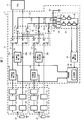
- FIG. 2 is a circuit diagram showing a state in a case where an interelectrode voltage Va-Vb is obtained in the photovoltaic power generation system shown in FIG.
- FIG. 2 is a circuit diagram illustrating a state in a case where a first voltage is obtained in the photovoltaic power generation system illustrated in FIG. 1.
- FIG. 2 is a circuit diagram showing the state in the case of calculating
- FIG. 2 is a circuit diagram showing a state where a solar cell string to be inspected is switched in the solar power generation system shown in FIG. 1.
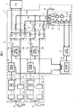
- FIG. 1 is a circuit diagram illustrating a configuration of a photovoltaic power generation system including the inspection apparatus according to the present embodiment.
- the photovoltaic power generation system 1 includes a plurality of solar cell strings 11, a ground fault detection device (inspection device) 12, and a power conditioning system (hereinafter referred to as PCS) 13 as a power conversion device.
- PCS power conditioning system
- FIG. 1 shows a state where the power generated by the solar cell string 11 is supplied to the PCS 13 and the ground fault detection device 12 is not operating (power output state).
- the solar cell string 11 is configured by connecting a plurality of solar cell modules 21 such as 10 to 20 in series.
- Each solar cell module 21 includes a plurality of solar cells (not shown) connected in series, and is formed in a panel shape.
- the ground fault resistance 22 is a resistance between the current path of the solar cell string 11 and the ground.
- Each solar cell string 11 is connected to the PCS 13 by power conducting paths 23a and 23b.
- the power supply paths 23 a and 23 b are provided for each solar cell string 11.
- the ground fault detection device 12 obtains an insulation resistance value between the solar cell string 11 and the ground point, and determines that a ground fault has occurred when the obtained insulation resistance value is smaller than a reference resistance value.
- the ground fault detection device 12 includes a power conduction path switch (first switching unit) 31, a PV switching switch (second switching unit) 32, a ground fault current detection circuit (inspection unit) 33, and a PV current detection unit. (Current measurement unit) 34, PV voltage detection unit (voltage measurement unit) 35, control unit (determination unit) 36, inspection first and second current paths (current paths) 37a, 37b, ground current path 38, and voltage detection unit 39 is provided.
- the power energization path changeover switch 31 is provided in the power energization paths 23a and 23b corresponding to each solar cell string 11, and switches the connection of the solar cell string 11 between the PCS 13 side and the ground fault current detection circuit 33 side. Specifically, the connection of the power conduction paths 23a and 23b, which are power output lines from the solar cell string 11, is switched between the PCS 13 side and the inspection first and second conduction paths 37a and 37b side.
- the inspection first and second energization paths 37 a and 37 b are provided corresponding to each solar cell string 11, and connect the power energization path switch 31 and the ground fault current detection circuit 33.
- PV changeover switch 32 is provided in inspection 1st and 2nd energization ways 37a and 37b corresponding to each solar cell string 11, and opens and closes inspection 1st and 2nd energization ways 37a and 37b.
- the ground fault current detection circuit 33 detects a ground fault current generated when a ground fault occurs in the solar cell string 11.
- the ground fault current detection circuit 33 includes an inspection first changeover switch 41, an inspection second changeover switch 42, an inspection third energization path 43, an inspection resistor R1, and voltage dividing resistors R2 to R5 that are protective resistors. Yes.
- the inspection first changeover switch 41 is connected to one end of the inspection third energization path 43, and the connection of one end of the inspection third energization path 43 is connected to the inspection first changeover switch 41. It switches between 37a and the earthing
- the inspection second changeover switch 42 is connected to the other end of the inspection third energization path 43, and the connection of the other end of the inspection third energization path 43 is connected to the inspection first changeover switch 41. Switching between the energization path 37b and the grounded energization path 38 that is grounded is performed.
- the inspection third energizing path 43 is provided with a detection resistor R1 and voltage dividing resistors R2 to R5 in series.
- the voltage dividing resistors R2 to R3 are provided between the detection resistor R1 and the inspection first changeover switch 41, and the voltage dividing resistors R4 to R5 are provided between the detection resistor R1 and the inspection second changeover switch 42. Yes.
- the voltage across the detection resistor R1 is input to the control unit 36 via the voltage detection unit 39.
- the number of voltage dividing resistors is four, but may be two. However, the risk of an accident due to a short circuit failure can be reduced by using a large number of voltage dividing resistors.
- the voltage dividing resistors R2 to R5 lower the first and second voltages V1 and V2 generated at both ends of the detection resistor R1, thereby reducing the voltage input to the control unit 36.
- the control unit 36 can be configured by a microcomputer, and the ground fault detection device 12 can be miniaturized.
- the voltage dividing resistors R2 to R5 exist in any of a circuit for obtaining the interelectrode voltage Va-Vb, a circuit for obtaining the first voltage V1, and a circuit for obtaining the second voltage V2. .
- Each PV current detection unit 34 is provided in, for example, the power energizing path 23a corresponding to each solar cell string 11, and detects and detects the amount of current flowing through the power energizing path 23a, that is, the amount of current flowing from the solar cell string 11 to the PCS 13. The result is output to the control unit 36.
- the PV voltage detection unit 35 detects the interelectrode voltage Va-Vb (voltage between PN terminals) of the solar cell string 11 and outputs the detection result to the control unit 36.
- the voltage detection unit 39 detects the voltage across the detection resistor R1 in the ground fault current detection circuit 33 and outputs the detection result to the control unit 36.
- the control unit 36 determines the power generation current of the solar cell string 11 detected by the PV current detection unit 34 and the power generation voltage (interelectrode voltage Va ⁇ Vb) of the solar cell string 11 detected by the PV voltage detection unit 35. Monitoring is performed to determine whether or not the solar cell string 11 is in a switchable state. In addition, the control unit 36 controls the switching operation of the power conduction path switch 31, the PV switch 32, the test first switch 41 and the test second switch 42, and a ground fault occurs in the solar cell string 11. The ground fault resistance and the ground fault position are obtained.
- the control unit 36 includes a storage unit 40 that stores various information such as a detection result of the presence or absence of a ground fault of the solar cell string 11 and a ground fault position when a ground fault occurs.
- a ground fault detection device is mentioned as an example of the inspection unit, but there is no problem even if it is a failure detection device for solar cells other than the ground fault.
- An example of a failure other than a ground fault is a broken circuit.
- FIG. 2 is a flowchart showing the operation of the ground fault detection device 12.
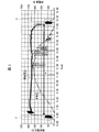
- FIG. 3 is a graph showing changes in the open circuit voltage and the amount of power generation in the solar cell string 11 on the day when the solar power generation system 1 is inspected by the ground fault detection device 12.
- the ground fault detection device 12 inspects the solar cell string 11 for a ground fault when the solar cell string 11 is in a switchable state.
- the switchable state is a state where the power generation amount (output current) of the solar cell string 11 is sufficiently small (for example, the output current of the solar cell string 11 is equal to the standby current of the PCS 13). The same level or a state smaller than the standby current of the PCS 13) (P part).
- the power generation amount (output current) is sufficiently small (for example, the output current of the solar cell string 11 is equal to the standby current of the PCS 13).
- the same level or smaller than the standby current of the PCS 13) Q section). Part P occurs early in the morning and part Q occurs in the evening.
- a range A indicates the operation time of the PCS 13.
- a condition that the output voltage (open voltage) of the solar cell string 11 is larger than zero may be added. By doing so, it is possible to perform an inspection using the generated current of the solar cell string 11.
- the above switchable state satisfies at least the condition that the output voltage of the solar cell string 11 is equal to or lower than the first threshold (for example, equal to or lower than the upper limit value of the specified output voltage in the normal power generation state of the solar cell string 11). Yes.
- the switchable state may further include a condition that the output voltage of the solar cell string 11 is greater than zero.
- the first threshold value may be, for example, 1 ⁇ 2 of the average value of the output voltage of the solar cell string 11 during the operation time of the PCS 13.
- the switchable state is, for example, a state where the value of the output voltage of the solar cell string 11 is equal to or less than the threshold value set to a value larger than zero and smaller than the average value of the output voltage during the operation time of the PCS 13. Also good.
- the state in which the output current of the solar cell string abnormally increases due to some failure can be excluded from the switchable state, and the output current of the solar cell string 11 is normal in the solar cell string 11.
- a condition of a second threshold value or less indicating that the state is present may be included.
- the switchable state may satisfy the condition that the value of the output current of the solar cell string 11 is equal to or less than the threshold value set to a value smaller than the average value of the output current during the operation time of the PCS 13.
- the second threshold value may be, for example, 1 ⁇ 2 of the average value of the output current of the solar cell string 11 during the operation time of the PCS 13.
- the power energization path switch 31 corresponding to each solar cell string 11 is switched to the PCS 13 side, and the PV switch 32 is off. (S11).
- the control unit 36 of the ground fault detection device 12 monitors the output voltage and the output current of the solar cell string 11 based on the detection results of the PV current detection unit 34 and the PV voltage detection unit 35 (S12), and thereby the solar cell. It is determined whether the string 11 is in a switchable state (S13).
- the control unit 36 sets all the power conduction path switching switches 31 from the PCS 13 side to the ground fault current detection circuit 33 side. (S14). As a result, all the solar cell strings 11 are disconnected from the PCS 13 by the switching operation of the power conduction path switch 31.
- the control unit 36 performs this control on the power supply path switching switch 31 when, for example, at least one solar cell string 11 is in a switchable state. That is, for each solar cell string 11, there may be a slight time difference in rising to the switchable state due to a subtle difference in the arrangement angle of the solar cell modules, the arrangement position, or the like. Note that the output current of the solar cell string 11 rises later than the output voltage.
- control unit 36 turns on the PV selector switch 32 corresponding to the solar cell string 11 to be inspected (S15, see FIG. 4).
- the solar cell string 11 corresponding to the PV change-over switch 32 that is turned on is connected to the ground fault current detection circuit 33 via the first and second conducting paths 37a and 37b, and the presence or absence of the ground fault is inspected. Is done.
- the PV switch 32 can be easily turned on and off. It can be carried out.
- the solar cell string 11 to be inspected in S15 is any one of the solar cell strings 11 selected in a predetermined order.
- the predetermined order may be, for example, the order of the solar cell strings 11 in a switchable state.
- the solar cell string 11 to be inspected is inspected for the occurrence of a ground fault, and when a ground fault has occurred, a ground fault position is further detected (S16).
- the control unit 36 determines that the inspection is possible when the condition that the output voltage of the solar cell string 11 is greater than zero is satisfied, turns on the PV changeover switch 32 corresponding to the solar cell string 11 to be inspected,
- the ground fault current detection circuit 33 may inspect the solar cell string 11 to be inspected for the presence of a ground fault.
- the control unit 36 inspects the management device (not shown) of the photovoltaic power generation system 1. That the ground fault has occurred about the solar cell string 11 and the position of the ground fault are notified (S18). Information such as the presence / absence of a ground fault and the position of the ground fault is stored in the storage unit 40.
- control unit 36 turns off the PV changeover switch 32 corresponding to the solar cell string 11 to be inspected (S19), and proceeds to the operation of S21.
- control unit 36 determines whether or not the inspection for all the solar cell strings 11 is completed (S21), and performs the operation of S22 if the inspection is completed. On the other hand, if the inspection is not completed, the process returns to S15 and the operations after S15 are repeated. That is, as shown in FIG. 7, the control unit 36 turns on the PV changeover switch 32 corresponding to the next solar cell string 11 to be inspected. In the same manner, the presence or absence of a ground fault of the solar cell string 11 is inspected in the same manner.
- the grounded solar cell string 11 is connected to the PCS 13 (S21), and the ground fault tested solar cell string 11 is transferred to the PCS 13. Electric power can be supplied. As a result, even if the inspected solar cell string 11 has some trouble (failure that is repaired but not urgent), the power generation function of the solar cell string 11 can be used effectively. However, instead of the above-described operation, only the solar cell string 11 having no abnormality (no ground fault) as a result of the ground fault inspection may be connected to the PCS 13.
- FIG. 4 is a circuit diagram showing a state in the case where the interelectrode voltage Va-Vb is obtained in the photovoltaic power generation system 1 shown in FIG.
- FIG. 5 is a circuit diagram showing a state when the first voltage V1 is obtained in the photovoltaic power generation system 1 shown in FIG.
- FIG. 6 is a circuit diagram showing a state when the second voltage V2 is obtained in the photovoltaic power generation system 1 shown in FIG.
- the control unit 36 connects the inspection first changeover switch 41 to one end of the inspection third energization path 43 with the inspection first energization path 37a as shown in FIG.
- the second changeover switch 42 is switched so that the other end of the inspection third energization path 43 is connected to the inspection second energization path 37b.
- both positive and negative poles of the solar cell string 11 are connected via the detection resistor R1 and the voltage dividing resistors R2 to R5.
- a voltage corresponding to the resistance value of the detection resistor R1 when the voltage between the positive and negative of the solar cell string 11 is divided by the detection resistor R1 and the voltage dividing resistors R2 to R5 is generated at both ends of the detection resistor R1.
- This voltage is taken into the control unit 36 via the voltage detection unit 39, and the control unit 36 obtains the interelectrode voltage Va-Vb.
- the control part 36 connects the test
- the inspection second changeover switch 42 is switched so that the other end of the inspection third energization path 43 is connected to the ground energization path 38.
- the positive electrode (P terminal) of the solar cell string 11 is grounded via the detection resistor R1 and the voltage dividing resistors R2 to R5.
- both ends of the detection resistor R1 correspond to the resistance value of the detection resistor R1 when the voltage between the positive electrode of the solar cell string 11 and the ground potential is divided by the detection resistor R1 and the voltage dividing resistors R2 to R5.
- the first voltage V1 is generated.
- the first voltage V1 is taken into the control unit 36 via the voltage detection unit 39, and the control unit 36 obtains the first voltage V1.
- the control unit 36 connects the inspection first changeover switch 41 so that one end of the inspection third energization path 43 is connected to the ground energization path 38, as shown in FIG.
- the inspection second switching switch 42 is switched so that the other end of the inspection third energization path 43 is connected to the inspection second energization path 37b.
- the negative electrode (N terminal) of the solar cell string 11 is grounded via the detection resistor R1 and the voltage dividing resistors R2 to R5.
- both ends of the detection resistor R1 correspond to the resistance value of the detection resistor R1 when the voltage between the negative electrode of the solar cell string 11 and the ground potential is divided by the detection resistor R1 and the voltage dividing resistors R2 to R5.
- a second voltage V2 is generated.
- the second voltage V2 is taken into the control unit 36 via the voltage detection unit 39, and the control unit 36 obtains the second voltage V2. Note that the order of obtaining the interelectrode voltage Va-Vb, the first voltage V1, and the second voltage V2 is in no particular order.
- the control unit 36 compares the resistance value Rleake (insulation resistance) with a reference resistance value (threshold value), and determines that a ground fault has occurred when the resistance value Rleake is smaller than the reference resistance value.
- the control unit 36 obtains a ground fault occurrence position (ground fault position) from the ratio of the absolute values of the first and second voltages V1, V2.
- the solar cell string 11 is obtained by connecting five solar cell modules 21 in series, and the ground fault is the fourth solar cell module 21 and the fourth solar cell module 21 when viewed from the P terminal side of the solar cell string 11.
- Reference numeral 22 represents a ground fault resistance at the ground fault position.
- the ratio between the absolute value of the first voltage V1 and the absolute value of the second voltage V2 is
- 3: 2
- the ground fault position can be obtained from this ratio.
- the ground fault detection device 12 switches all the power energization path switch 31 from, for example, the PCS 13 side to the ground fault current detection circuit 33 side all at once. After that, each solar cell string 11 is sequentially inspected for the occurrence of a ground fault.
- the switchable state satisfies at least the condition that the output voltage of the solar cell string 11 is equal to or lower than the first threshold (for example, equal to or lower than the upper limit value of the specified output voltage in the normal power generation state of the solar cell string 11).
- the switchable state satisfies the condition that the output current of the solar cell string 11 is equal to or lower than a second threshold value indicating that the solar cell string is in a normal state.
- the conditions that the value of the output current of the solar cell string 11 is below the 2nd threshold value set to the value smaller than the average value of the output current in the operation time of PCS13 are satisfy
- a small and inexpensive relay with low power resistance can be used for the power energization path changeover switch 31 of the ground fault detection device 12, and the ground fault detection device 12 can be configured to be small and low cost. it can.
- the ground fault current detection circuit 33 sequentially inspects the plurality of solar cell strings 11, it takes a long time to complete the inspection of all the solar cell strings 11, the amount of sunlight increases, and the solar cell string It is conceivable that the output voltage and output current of 11 rise beyond the switchable state. However, even if it becomes such a state, since the electric power supply path switch 31 has already been switched from the PCS 13 side to the ground fault current detection circuit 33 side, it is affected by such a change in the solar cell string 11. The inspection can be easily performed without any problem.
- the switchable state is determined when the output voltage of the solar cell string 11 satisfies at least the condition of the first threshold value or less. Moreover, it determines with the switchable state, when the output current of the solar cell string 11 satisfy
- the solar power generation system 1 is set as the structure provided with the ground fault detection apparatus 12 as an example of an inspection apparatus.
- the inspection device is not limited to the one that detects the ground fault of the solar cell string 11, and may be one that detects the disconnection of the solar cell string 11 with a conventionally known configuration. That is, the inspection device provided in the solar power generation system 1 may be any inspection device that inspects the solar cell string 11 separately from the PCS 13 in a switchable state, such as a ground fault inspection device or a disconnection inspection device of the solar cell string 11. .
- the case where the output voltages of the solar cell strings 11 are equal is described as an example.
- a so-called multistring PCS in which a booster is provided for each solar cell string 11 may be used.
- the solar cell string 11 whose voltage rises earliest in the early morning is extracted from the past measurement history and selected as a reference string, and each solar cell is based on the reference string.
- the switching timing of the string 11 may be determined.
- the ground fault detection device 12 is not limited to the configuration provided with the ground fault current detection circuit 33 shown in the above embodiment, and may detect a ground fault with a conventionally known configuration. Good.
- the ground fault detection device 12 may include a sunshine meter that measures the amount of sunshine of the solar cell string 11 and a clock that detects early morning and evening as auxiliary means for detecting the switchable state.
- An inspection apparatus for a photovoltaic power generation system includes: a voltage measuring unit that measures an output voltage of the solar cell string; in the inspection apparatus for a solar power generation system that inspects a plurality of solar cell strings connected to a power converter; An inspection unit that inspects the solar cell string, a first switching unit that is provided for each solar cell string, and switches the connection of the solar cell string between the power conversion device side and the inspection unit side; When the output voltage of the solar cell string satisfies at least the condition of a first threshold value or less, a determination unit that determines that the switchable state is possible, and when each of the solar cell strings is in the switchable state, each of the first switching And a control unit that controls the unit to switch to the inspection unit side.
- the voltage measurement unit measures the output voltage of the solar cell string, and the determination unit satisfies at least the condition that the output voltage of the solar cell string is equal to or lower than the first threshold (for example, early morning or evening) In the case of).
- the control unit controls the first switching unit to switch to the inspection unit side when the solar cell string is in a switchable state.
- inspection part can test
- each of the first switching units provided for each solar cell string is, for example, all at once when the solar cell string is in a switchable state, from the power converter side to the inspection unit side.
- Switch Therefore, a small and inexpensive switch (for example, a relay) with low power resistance can be used for the first switching unit, and the inspection device can be configured to be small and low cost.
- the inspection unit when the inspection unit is in a switchable state, for example, in the case of sequentially inspecting a plurality of solar cell strings in the early morning, if it takes a long time to complete the inspection of all the solar cell strings, the amount of sunlight increases, It is conceivable that the output voltage and output current of the solar cell string increase. In this case, when the power conversion device operates, a current flows from the solar cell string connected to the power conversion device to the power conversion device, and the first switching unit is a small switch. It becomes difficult to switch the string from the power converter side to the inspection unit side.
- each first switching unit already powers each solar cell string. It has been switched from the conversion device side to the inspection unit side. Therefore, the inspection can be easily performed without being affected by the change in the solar cell string as described above. That is, the output current of the solar cell string is controlled to a minute current by the inspection unit, and the inspection can be easily performed without being affected by the change of the solar cell string.
- the determination unit may determine that the inspection unit is in an inspectable state when a condition that the output voltage of the solar cell string is greater than zero is satisfied.
- a solar cell string in the electric power generation state of a solar cell string, or a substantially electric power generation state, a solar cell string is switched from the power converter device side to the said test
- the switching operation (switchable state) from the power conversion device side to the inspection unit side of the connection of the solar cell string by the first switching unit is limited based on the upper limit voltage of the voltage within a predetermined range, and by the inspection unit
- the inspection (inspectable state) is limited based on the lower limit voltage of the voltage within the predetermined range.
- the inspection apparatus for the solar power generation system further includes a current measurement unit that measures an output current of the solar cell string, and the determination unit further includes that the output current of the solar cell string is equal to or less than a second threshold value. It is good also as a structure which determines with the said switchable state, when satisfy
- a determination part is further switched when the output current of a solar cell string is below a 2nd threshold value (for example, below the upper limit of the output current which shows that a solar cell string is a normal state). Judged as possible.
- the inspection unit sequentially performs inspection on each of the solar cell strings, and the control unit converts the solar cell string that has been inspected by the inspection unit into the power conversion device. It is good also as a structure which controls the said 1st switching part so that it may be connected.
- the power generation function of the solar cell string can be used effectively.
- the inspection apparatus for the solar power generation system further includes a second switching unit that opens and closes each energization path between each of the first switching units and the inspection unit, and the control unit is configured to inspect the sun to be inspected. While the battery string is sequentially connected to the inspection unit, the second switching unit may be controlled so that the solar cell string that has been inspected is disconnected from the inspection unit.
- the solar cell strings to be inspected are sequentially connected to the inspection unit, while the solar cell strings that have been inspected are disconnected from the inspection unit. Therefore, the inspection of each solar cell string by the inspection unit can be appropriately performed sequentially.
- An inspection method for a solar power generation system is an inspection method for a solar power generation system for inspecting a plurality of solar cell strings connected to a power converter, and an inspection step for inspecting the solar cell string, and the solar cell
- the determination step of determining the switchable state, and the determination step determines that each of the solar cells is in the switchable state.
- the present invention can be used for an apparatus for inspecting a ground fault or disconnection of a plurality of solar cell strings provided in a solar power generation system.
Landscapes
- Engineering & Computer Science (AREA)
- Power Engineering (AREA)
- Photovoltaic Devices (AREA)
- Testing Of Short-Circuits, Discontinuities, Leakage, Or Incorrect Line Connections (AREA)
Abstract
L'objectif de la présente invention est de rendre possible l'utilisation d'un commutateur à faible coût. Un dispositif de détection de défaut à la terre (12) est pourvu : d'une unité de détection de courant photovoltaïque (PV) (34) ; d'un circuit de détection de courant de défaut à la terre (33) ; de commutateurs sélecteurs de chemin d'alimentation (31) pour commuter la connexion de chaînes de cellules photovoltaïques (11) vers le côté PCS (13) ou vers le circuit de détection de courant de défaut à la terre (33) ; et d'une unité de commande (36) pour, lorsque les chaînes de cellules photovoltaïques (11) sont dans un état commutable, commuter les commutateurs sélecteurs de chemin d'alimentation (31) respectifs vers le côté circuit de détection de courant de défaut à la terre (33).
Priority Applications (2)
| Application Number | Priority Date | Filing Date | Title |
|---|---|---|---|
| EP16807152.0A EP3282578A4 (fr) | 2015-06-09 | 2016-02-03 | Procédé et dispositif de test de système de production d'énergie photovoltaïque |
| US15/789,246 US20180041164A1 (en) | 2015-06-09 | 2017-10-20 | Solar power generation system inspection method and inspection apparatus |
Applications Claiming Priority (2)
| Application Number | Priority Date | Filing Date | Title |
|---|---|---|---|
| JP2015-116961 | 2015-06-09 | ||
| JP2015116961A JP2017005852A (ja) | 2015-06-09 | 2015-06-09 | 太陽光発電システムの検査方法および検査装置 |
Related Child Applications (1)
| Application Number | Title | Priority Date | Filing Date |
|---|---|---|---|
| US15/789,246 Continuation US20180041164A1 (en) | 2015-06-09 | 2017-10-20 | Solar power generation system inspection method and inspection apparatus |
Publications (1)
| Publication Number | Publication Date |
|---|---|
| WO2016199445A1 true WO2016199445A1 (fr) | 2016-12-15 |
Family
ID=57503336
Family Applications (1)
| Application Number | Title | Priority Date | Filing Date |
|---|---|---|---|
| PCT/JP2016/053183 Ceased WO2016199445A1 (fr) | 2015-06-09 | 2016-02-03 | Procédé et dispositif de test de système de production d'énergie photovoltaïque |
Country Status (4)
| Country | Link |
|---|---|
| US (1) | US20180041164A1 (fr) |
| EP (1) | EP3282578A4 (fr) |
| JP (1) | JP2017005852A (fr) |
| WO (1) | WO2016199445A1 (fr) |
Families Citing this family (5)
| Publication number | Priority date | Publication date | Assignee | Title |
|---|---|---|---|---|
| KR101868433B1 (ko) * | 2017-07-28 | 2018-07-23 | 한국산전(주) | 태양광 모듈 스트링 사고예방을 위한 스트링 블록 디바이스가 구비된 태양광 발전 시스템용 접속반 및 이를 구비한 태양광발전시스템 |
| JP6930370B2 (ja) * | 2017-10-30 | 2021-09-01 | オムロン株式会社 | 地絡検出装置 |
| KR102630252B1 (ko) * | 2018-08-28 | 2024-01-29 | 엘지이노텍 주식회사 | 태양광 연계 에너지 저장 시스템용 dc-dc 컨버터 및 그 제어방법 |
| US12063011B2 (en) | 2018-10-31 | 2024-08-13 | The University Of Queensland | Solar farm fault detection and diagnosis |
| KR20230148908A (ko) * | 2022-04-19 | 2023-10-26 | 주식회사 엘지에너지솔루션 | 에너지 저장 시스템 및 에너지 저장 시스템의 접지구조 제어 장치 |
Citations (2)
| Publication number | Priority date | Publication date | Assignee | Title |
|---|---|---|---|---|
| JP2013065797A (ja) * | 2011-09-20 | 2013-04-11 | Tokyo Univ Of Science | 太陽電池アレイの診断装置、パワーコンディショナ、太陽電池アレイの診断方法、及びプログラム |
| JP2013069974A (ja) * | 2011-09-26 | 2013-04-18 | System Jd:Kk | 太陽電池アレイの検査装置 |
Family Cites Families (3)
| Publication number | Priority date | Publication date | Assignee | Title |
|---|---|---|---|---|
| JPH07177652A (ja) * | 1993-12-17 | 1995-07-14 | Canon Inc | 太陽光発電システムおよび太陽光発電システムの保護方式 |
| JP5642030B2 (ja) * | 2011-08-01 | 2014-12-17 | Jx日鉱日石エネルギー株式会社 | 地絡検出装置、地絡検出方法、太陽光発電システム、及び地絡検出プログラム |
| JP2014081669A (ja) * | 2012-10-12 | 2014-05-08 | Ntt Facilities Inc | 電力供給システム、電力供給制御装置、電力供給制御方法、及びプログラム |
-
2015
- 2015-06-09 JP JP2015116961A patent/JP2017005852A/ja active Pending
-
2016
- 2016-02-03 WO PCT/JP2016/053183 patent/WO2016199445A1/fr not_active Ceased
- 2016-02-03 EP EP16807152.0A patent/EP3282578A4/fr not_active Withdrawn
-
2017
- 2017-10-20 US US15/789,246 patent/US20180041164A1/en not_active Abandoned
Patent Citations (2)
| Publication number | Priority date | Publication date | Assignee | Title |
|---|---|---|---|---|
| JP2013065797A (ja) * | 2011-09-20 | 2013-04-11 | Tokyo Univ Of Science | 太陽電池アレイの診断装置、パワーコンディショナ、太陽電池アレイの診断方法、及びプログラム |
| JP2013069974A (ja) * | 2011-09-26 | 2013-04-18 | System Jd:Kk | 太陽電池アレイの検査装置 |
Non-Patent Citations (1)
| Title |
|---|
| See also references of EP3282578A4 * |
Also Published As
| Publication number | Publication date |
|---|---|
| EP3282578A4 (fr) | 2018-03-28 |
| EP3282578A1 (fr) | 2018-02-14 |
| US20180041164A1 (en) | 2018-02-08 |
| JP2017005852A (ja) | 2017-01-05 |
Similar Documents
| Publication | Publication Date | Title |
|---|---|---|
| JP5443327B2 (ja) | 組電池装置 | |
| JP4780416B2 (ja) | 太陽電池アレイ故障診断方法 | |
| JP6390359B2 (ja) | 太陽光発電システムの検査方法および検査装置 | |
| US20120049627A1 (en) | Current collecting box for photovoltaic power generation | |
| EP2626712B1 (fr) | Appareil de détection de défauts | |
| JP5642030B2 (ja) | 地絡検出装置、地絡検出方法、太陽光発電システム、及び地絡検出プログラム | |
| JP6158916B2 (ja) | 蓄電装置の異常検出回路およびそれを備えた蓄電装置 | |
| WO2012073836A1 (fr) | Dispositif, procédé et programme de détection de défaut de mise à la terre et système générateur à énergie solaire | |
| EP2741094A1 (fr) | Dispositif de détection de défaut de terre, procédé de détection de défaut de terre, système d'énergie solaire et programme détection de défaut de terre | |
| US10436853B2 (en) | Failure detection apparatus | |
| KR20120027181A (ko) | 태양광 발전기 고장 진단 방법 | |
| WO2016199445A1 (fr) | Procédé et dispositif de test de système de production d'énergie photovoltaïque | |
| JP6597394B2 (ja) | アーク発生位置検出装置およびアーク発生位置検出方法 | |
| JP6481571B2 (ja) | 検査装置および検査方法 | |
| KR101728690B1 (ko) | 태양광 발전에서의 실시간 고장 알림 시스템 및 방법 | |
| JP6702168B2 (ja) | 太陽光発電システムの検査装置および検査方法 | |
| WO2016031269A1 (fr) | Dispositif de détection de défaut à la terre et procédé de détection de défaut à la terre | |
| JP2015188306A (ja) | 太陽電池回路の検査装置及び検査方法 | |
| JP6405932B2 (ja) | 地絡検出装置および地絡検出方法 | |
| JP6541485B2 (ja) | 駅舎補助電源用地絡検出装置 | |
| EP4456417A1 (fr) | Appareil d'inspection d'état d'isolation de module photovoltaïque, et procédé d'inspection d'état d'isolation au moyen de ce dernier | |
| JP7073802B2 (ja) | 太陽光発電システムの故障検査装置 | |
| JP2016123232A (ja) | 太陽電池の検査方法およびその装置並びに太陽電池検査装置に用いられる信号源 | |
| JP6428396B2 (ja) | 太陽光発電システムの検査方法および検査装置 | |
| JP2017147931A (ja) | 太陽電池検査装置および太陽電池検査方法 |
Legal Events
| Date | Code | Title | Description |
|---|---|---|---|
| 121 | Ep: the epo has been informed by wipo that ep was designated in this application |
Ref document number: 16807152 Country of ref document: EP Kind code of ref document: A1 |
|
| NENP | Non-entry into the national phase |
Ref country code: DE |