WO2016199465A1 - Bus articulé - Google Patents
Bus articulé Download PDFInfo
- Publication number
- WO2016199465A1 WO2016199465A1 PCT/JP2016/057202 JP2016057202W WO2016199465A1 WO 2016199465 A1 WO2016199465 A1 WO 2016199465A1 JP 2016057202 W JP2016057202 W JP 2016057202W WO 2016199465 A1 WO2016199465 A1 WO 2016199465A1
- Authority
- WO
- WIPO (PCT)
- Prior art keywords
- electric wire
- vehicle
- voltage electric
- wire portion
- low
- Prior art date
- Legal status (The legal status is an assumption and is not a legal conclusion. Google has not performed a legal analysis and makes no representation as to the accuracy of the status listed.)
- Ceased
Links
Images


Classifications
-
- B—PERFORMING OPERATIONS; TRANSPORTING
- B60—VEHICLES IN GENERAL
- B60K—ARRANGEMENT OR MOUNTING OF PROPULSION UNITS OR OF TRANSMISSIONS IN VEHICLES; ARRANGEMENT OR MOUNTING OF PLURAL DIVERSE PRIME-MOVERS IN VEHICLES; AUXILIARY DRIVES FOR VEHICLES; INSTRUMENTATION OR DASHBOARDS FOR VEHICLES; ARRANGEMENTS IN CONNECTION WITH COOLING, AIR INTAKE, GAS EXHAUST OR FUEL SUPPLY OF PROPULSION UNITS IN VEHICLES
- B60K6/00—Arrangement or mounting of plural diverse prime-movers for mutual or common propulsion, e.g. hybrid propulsion systems comprising electric motors and internal combustion engines
- B60K6/20—Arrangement or mounting of plural diverse prime-movers for mutual or common propulsion, e.g. hybrid propulsion systems comprising electric motors and internal combustion engines the prime-movers consisting of electric motors and internal combustion engines, e.g. HEVs
- B60K6/42—Arrangement or mounting of plural diverse prime-movers for mutual or common propulsion, e.g. hybrid propulsion systems comprising electric motors and internal combustion engines the prime-movers consisting of electric motors and internal combustion engines, e.g. HEVs characterised by the architecture of the hybrid electric vehicle
- B60K6/48—Parallel type
- B60K6/485—Motor-assist type
-
- B—PERFORMING OPERATIONS; TRANSPORTING
- B60—VEHICLES IN GENERAL
- B60K—ARRANGEMENT OR MOUNTING OF PROPULSION UNITS OR OF TRANSMISSIONS IN VEHICLES; ARRANGEMENT OR MOUNTING OF PLURAL DIVERSE PRIME-MOVERS IN VEHICLES; AUXILIARY DRIVES FOR VEHICLES; INSTRUMENTATION OR DASHBOARDS FOR VEHICLES; ARRANGEMENTS IN CONNECTION WITH COOLING, AIR INTAKE, GAS EXHAUST OR FUEL SUPPLY OF PROPULSION UNITS IN VEHICLES
- B60K1/00—Arrangement or mounting of electrical propulsion units
- B60K1/04—Arrangement or mounting of electrical propulsion units of the electric storage means for propulsion
-
- B—PERFORMING OPERATIONS; TRANSPORTING
- B60—VEHICLES IN GENERAL
- B60K—ARRANGEMENT OR MOUNTING OF PROPULSION UNITS OR OF TRANSMISSIONS IN VEHICLES; ARRANGEMENT OR MOUNTING OF PLURAL DIVERSE PRIME-MOVERS IN VEHICLES; AUXILIARY DRIVES FOR VEHICLES; INSTRUMENTATION OR DASHBOARDS FOR VEHICLES; ARRANGEMENTS IN CONNECTION WITH COOLING, AIR INTAKE, GAS EXHAUST OR FUEL SUPPLY OF PROPULSION UNITS IN VEHICLES
- B60K6/00—Arrangement or mounting of plural diverse prime-movers for mutual or common propulsion, e.g. hybrid propulsion systems comprising electric motors and internal combustion engines
- B60K6/20—Arrangement or mounting of plural diverse prime-movers for mutual or common propulsion, e.g. hybrid propulsion systems comprising electric motors and internal combustion engines the prime-movers consisting of electric motors and internal combustion engines, e.g. HEVs
- B60K6/22—Arrangement or mounting of plural diverse prime-movers for mutual or common propulsion, e.g. hybrid propulsion systems comprising electric motors and internal combustion engines the prime-movers consisting of electric motors and internal combustion engines, e.g. HEVs characterised by apparatus, components or means specially adapted for HEVs
- B60K6/40—Arrangement or mounting of plural diverse prime-movers for mutual or common propulsion, e.g. hybrid propulsion systems comprising electric motors and internal combustion engines the prime-movers consisting of electric motors and internal combustion engines, e.g. HEVs characterised by apparatus, components or means specially adapted for HEVs characterised by the assembly or relative disposition of components
-
- B—PERFORMING OPERATIONS; TRANSPORTING
- B60—VEHICLES IN GENERAL
- B60K—ARRANGEMENT OR MOUNTING OF PROPULSION UNITS OR OF TRANSMISSIONS IN VEHICLES; ARRANGEMENT OR MOUNTING OF PLURAL DIVERSE PRIME-MOVERS IN VEHICLES; AUXILIARY DRIVES FOR VEHICLES; INSTRUMENTATION OR DASHBOARDS FOR VEHICLES; ARRANGEMENTS IN CONNECTION WITH COOLING, AIR INTAKE, GAS EXHAUST OR FUEL SUPPLY OF PROPULSION UNITS IN VEHICLES
- B60K6/00—Arrangement or mounting of plural diverse prime-movers for mutual or common propulsion, e.g. hybrid propulsion systems comprising electric motors and internal combustion engines
- B60K6/20—Arrangement or mounting of plural diverse prime-movers for mutual or common propulsion, e.g. hybrid propulsion systems comprising electric motors and internal combustion engines the prime-movers consisting of electric motors and internal combustion engines, e.g. HEVs
- B60K6/42—Arrangement or mounting of plural diverse prime-movers for mutual or common propulsion, e.g. hybrid propulsion systems comprising electric motors and internal combustion engines the prime-movers consisting of electric motors and internal combustion engines, e.g. HEVs characterised by the architecture of the hybrid electric vehicle
- B60K6/48—Parallel type
-
- B—PERFORMING OPERATIONS; TRANSPORTING
- B62—LAND VEHICLES FOR TRAVELLING OTHERWISE THAN ON RAILS
- B62D—MOTOR VEHICLES; TRAILERS
- B62D47/00—Motor vehicles or trailers predominantly for carrying passengers
- B62D47/02—Motor vehicles or trailers predominantly for carrying passengers for large numbers of passengers, e.g. omnibus
- B62D47/025—Motor vehicles or trailers predominantly for carrying passengers for large numbers of passengers, e.g. omnibus articulated buses with interconnecting passageway, e.g. bellows
-
- B—PERFORMING OPERATIONS; TRANSPORTING
- B60—VEHICLES IN GENERAL
- B60D—VEHICLE CONNECTIONS
- B60D1/00—Traction couplings; Hitches; Draw-gear; Towing devices
-
- B—PERFORMING OPERATIONS; TRANSPORTING
- B60—VEHICLES IN GENERAL
- B60K—ARRANGEMENT OR MOUNTING OF PROPULSION UNITS OR OF TRANSMISSIONS IN VEHICLES; ARRANGEMENT OR MOUNTING OF PLURAL DIVERSE PRIME-MOVERS IN VEHICLES; AUXILIARY DRIVES FOR VEHICLES; INSTRUMENTATION OR DASHBOARDS FOR VEHICLES; ARRANGEMENTS IN CONNECTION WITH COOLING, AIR INTAKE, GAS EXHAUST OR FUEL SUPPLY OF PROPULSION UNITS IN VEHICLES
- B60K1/00—Arrangement or mounting of electrical propulsion units
- B60K1/04—Arrangement or mounting of electrical propulsion units of the electric storage means for propulsion
- B60K2001/0405—Arrangement or mounting of electrical propulsion units of the electric storage means for propulsion characterised by their position
- B60K2001/0411—Arrangement in the front part of the vehicle
-
- B—PERFORMING OPERATIONS; TRANSPORTING
- B60—VEHICLES IN GENERAL
- B60L—PROPULSION OF ELECTRICALLY-PROPELLED VEHICLES; SUPPLYING ELECTRIC POWER FOR AUXILIARY EQUIPMENT OF ELECTRICALLY-PROPELLED VEHICLES; ELECTRODYNAMIC BRAKE SYSTEMS FOR VEHICLES IN GENERAL; MAGNETIC SUSPENSION OR LEVITATION FOR VEHICLES; MONITORING OPERATING VARIABLES OF ELECTRICALLY-PROPELLED VEHICLES; ELECTRIC SAFETY DEVICES FOR ELECTRICALLY-PROPELLED VEHICLES
- B60L2200/00—Type of vehicles
- B60L2200/18—Buses
-
- B—PERFORMING OPERATIONS; TRANSPORTING
- B60—VEHICLES IN GENERAL
- B60W—CONJOINT CONTROL OF VEHICLE SUB-UNITS OF DIFFERENT TYPE OR DIFFERENT FUNCTION; CONTROL SYSTEMS SPECIALLY ADAPTED FOR HYBRID VEHICLES; ROAD VEHICLE DRIVE CONTROL SYSTEMS FOR PURPOSES NOT RELATED TO THE CONTROL OF A PARTICULAR SUB-UNIT
- B60W2300/00—Indexing codes relating to the type of vehicle
- B60W2300/10—Buses
-
- B—PERFORMING OPERATIONS; TRANSPORTING
- B60—VEHICLES IN GENERAL
- B60Y—INDEXING SCHEME RELATING TO ASPECTS CROSS-CUTTING VEHICLE TECHNOLOGY
- B60Y2200/00—Type of vehicle
- B60Y2200/10—Road Vehicles
- B60Y2200/14—Trucks; Load vehicles, Busses
- B60Y2200/143—Busses
- B60Y2200/1432—Low floor busses
-
- B—PERFORMING OPERATIONS; TRANSPORTING
- B62—LAND VEHICLES FOR TRAVELLING OTHERWISE THAN ON RAILS
- B62D—MOTOR VEHICLES; TRAILERS
- B62D12/00—Steering specially adapted for vehicles operating in tandem or having pivotally connected frames
- B62D12/02—Steering specially adapted for vehicles operating in tandem or having pivotally connected frames for vehicles operating in tandem
-
- Y—GENERAL TAGGING OF NEW TECHNOLOGICAL DEVELOPMENTS; GENERAL TAGGING OF CROSS-SECTIONAL TECHNOLOGIES SPANNING OVER SEVERAL SECTIONS OF THE IPC; TECHNICAL SUBJECTS COVERED BY FORMER USPC CROSS-REFERENCE ART COLLECTIONS [XRACs] AND DIGESTS
- Y02—TECHNOLOGIES OR APPLICATIONS FOR MITIGATION OR ADAPTATION AGAINST CLIMATE CHANGE
- Y02T—CLIMATE CHANGE MITIGATION TECHNOLOGIES RELATED TO TRANSPORTATION
- Y02T10/00—Road transport of goods or passengers
- Y02T10/60—Other road transportation technologies with climate change mitigation effect
- Y02T10/62—Hybrid vehicles
Definitions
- the present invention relates to an articulated bus in which a front vehicle and a rear vehicle are articulated in a swingable manner.
- the articulated bus is a bus in which openings are provided on the rear surface of the front vehicle and the front surface of the rear vehicle so that passengers can move between the front vehicle and the rear vehicle.
- This articulated bus is a towing (puller) articulated bus in which a front vehicle pulls a rear vehicle. Since the engine is disposed under the center floor of the front vehicle, the towed articulated bus becomes a two-step bus having a two-step step at the entrance and exit with the floor surface raised.
- non-step low-floor buses have been adopted in which the floor is lowered and steps are eliminated for the purpose of improving ease of getting on and off.
- the engine is disposed at the rear end of the vehicle, thereby realizing a low floor and a non-step.
- a hybrid system using two types of driving sources of an engine and a motor generator has been adopted (see, for example, Patent Document 1).
- the motor generator charges the HV battery by converting the kinetic energy of the rotating engine into electric energy, and rotates the electric energy charged in the HV battery to drive the vehicle.
- the motor generator is arranged at the rear end of the rear vehicle in the same manner as the engine. Moreover, since the motor generator and the HV battery are connected by a high-voltage electric wire, it is preferable to make the distance between the motor generator and the HV battery closer. For this reason, the HV battery is arranged on the roof of the rear vehicle.
- the motor generator and the HV battery of the hybrid system are heavy items of articulated buses. For this reason, when the motor generator is disposed at the rear end of the rear vehicle and the HV battery is disposed on the roof of the rear vehicle, the front vehicle becomes too light with respect to the rear vehicle, and the axle weight of the steered wheels is increased. Run short. As a result, steering stability is lowered, and further, uneven wear of tires and deterioration of the air bellows of the rear vehicle suspension are increased.
- an air conditioner unit evaporator
- evaporator is also arranged on the roof of each vehicle. Then, since the position of the center of gravity becomes high, a large change in the vehicle such as a tread expansion is necessary to secure the maximum stable inclination angle (turning angle). As a result, vehicle weight and manufacturing costs increase.
- an object of the present invention is to provide an articulated bus capable of suppressing a reduction in steering stability, an increase in weight of a rear vehicle, and an increase in cost.
- the present inventor has found that it is better to shorten the high-voltage electric wire, contrary to the technical common knowledge of those skilled in the art, the longer the high-voltage electric wire, the lower the steering stability. As a result, the inventors have found that the increase in weight and cost of rear vehicles can be suppressed.
- the articulated bus includes a front vehicle having a steering wheel and a rear wheel disposed rearward in the vehicle front-rear direction with respect to the steering wheel, and a vehicle front-rear direction rear of the front vehicle.
- a rear vehicle that is disposed and mounted with an engine, a joint that articulates the front vehicle and the rear vehicle, a motor generator that functions as a motor and a generator, and a motor generator that generates power.
- a hybrid system having an HV battery for storing electric energy and supplying electric energy to the motor generator.
- the HV battery is disposed on the roof of the front vehicle.
- the front vehicle for the rear vehicle is compared with the case where the HV battery is disposed on the roof of the rear vehicle.
- the weight ratio of increases.
- the position of the center of gravity of the rear vehicle is lowered as compared with the case where the HV battery is disposed on the roof of the rear vehicle.
- the HV battery may be disposed at the same position as the axle of the steering wheel in the vehicle front-rear direction.
- a high-voltage electric wire connected to the motor generator and the HV battery through which a higher-voltage current flows than the low-voltage electric wire, and the joint portion is a passage that communicates the front vehicle and the rear vehicle.
- a hood forming a space is provided, and the low-voltage electric wire is wired inside the hood, a first low-voltage electric wire portion wired inside the rear vehicle, a second low-voltage electric wire portion wired inside the front vehicle, and the hood.
- a third high-voltage cable section that may be provided.
- a first shielding portion made of metal that is disposed between the first low-voltage electric wire portion and the first high-voltage electric wire portion at the front end of the rear vehicle and shields the first low-voltage electric wire portion and the first high-voltage electric wire portion;
- the second shielding part made of metal which is disposed between the second low voltage electric wire part and the second high voltage electric cable part at the rear end of the front vehicle and shields the second low voltage electric cable part and the second high voltage electric cable part And may be provided.
- front and rear in the vehicle front-rear direction are also simply referred to as front and rear
- upper and lower in the vehicle vertical direction are also simply referred to as upper and lower.
- Fig. 1 is a schematic side view of an articulated bus.
- the articulated bus 1 of the present embodiment includes a front vehicle 2, a rear vehicle 3, a articulated portion 4, and a hybrid system 5.
- the front vehicle 2 is disposed on the front side of the articulated bus 1 in the vehicle front-rear direction.
- the front vehicle 2 is a driven vehicle on which an engine that drives the articulated bus 1 is not mounted.
- the front vehicle 2 has a low floor like a non-step bus. For this reason, the front vehicle 2 is not provided with a step for getting on and off.
- the front vehicle 2 is attached with a front wheel 23a located on the front side in the vehicle front-rear direction and a first rear wheel 23b located on the rear side in the vehicle front-rear direction with respect to the front wheel 23a.
- the front wheels 23a are steering wheels connected to a steering mechanism.
- the front wheel 23a and the first rear wheel 23b are driven wheels that are not rotationally driven.
- the front vehicle 2 includes a front chassis frame 21 and a front vehicle body 22.
- the front chassis frame 21 is composed of a plurality of skeleton members.
- the front chassis frame 21 includes at least a laterally extending portion 21a (see FIG. 2) extending in the vehicle width direction at the rear end portion in the vehicle front-rear direction.
- the laterally extending portion 21a is a member connected to the articulated portion 4 and is also called a bulkhead.
- the front vehicle body 22 is connected to the front chassis frame 21 to form a passenger compartment.
- a front vehicle air conditioner unit 25 and an HV (Hybrid Vehicle) battery 52 described later are disposed on the roof 24 of the front body 22 .
- the front vehicle air conditioner unit 25 includes an evaporator (not shown) that air-conditions the passenger compartment of the front vehicle 2.
- the front vehicle air conditioner unit 25 (particularly an evaporator) is disposed between the front wheel 23a and the first rear wheel 23b in the vehicle longitudinal direction.
- a passage opening (not shown) is formed at the rear end of the front vehicle body 22 for a passenger to travel between the front vehicle 2 and the rear vehicle 3.
- the rear vehicle 3 is disposed on the rear side in the vehicle front-rear direction of the articulated bus 1 and behind the front vehicle 2 in the vehicle front-rear direction.
- the rear vehicle 3 is a drive vehicle in which an engine E / G that drives the articulated bus 1 is mounted at a rear end portion in the vehicle front-rear direction.
- An alternator 36 that generates electric power by rotational driving of the engine E / G is mounted on the rear end of the rear vehicle 3 in the vehicle longitudinal direction.
- the rear vehicle 3 is lowered like a non-step bus. For this reason, the rear vehicle 3 is not provided with a step for getting on and off.
- the rear vehicle 3 is attached with a second rear wheel 33 located at the center in the vehicle longitudinal direction.
- the second rear wheel 33 is a drive wheel that is driven to rotate by the rotation of the engine E / G to drive the articulated bus 1.
- the second rear wheel 33 is disposed in front of the engine E / G in the vehicle longitudinal direction.
- the rear vehicle 3 includes a rear chassis frame 31 and a rear vehicle body 32.
- the rear chassis frame 31 is composed of a plurality of skeleton members.
- the rear chassis frame 31 includes at least a first laterally extending portion 31a (see FIG. 2) extending in the vehicle width direction at the front end portion in the vehicle front-rear direction.
- the first laterally extending portion 31a is a member connected to the articulating portion 4 and is also called a bulkhead.
- the rear vehicle body 32 is connected to the rear chassis frame 31 to form a passenger compartment.
- a rear vehicle air conditioner unit 35 is disposed on the roof 34 of the rear vehicle body 32.
- the rear vehicle air conditioner unit 35 includes an evaporator (not shown) that air-conditions the passenger compartment of the rear vehicle 3.
- the rear vehicle air conditioner unit 35 (particularly an evaporator) is disposed at a position between the front end of the rear vehicle 3 and the second rear wheel 33 in the vehicle front-rear direction.
- a passage opening (not shown) is formed at the front end of the rear vehicle body 32 for a passenger to move between the front vehicle 2 and the rear vehicle 3.
- FIG. 2 is a schematic plan view showing the articulated portion.
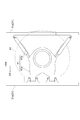
- 3 is a cross-sectional view of the joint portion taken along line III-III shown in FIG.
- the articulating portion 4 articulates the front chassis frame 21 and the rear chassis frame 31 between the front vehicle 2 and the rear vehicle 3 so as to be swingable.
- the articulated portion 4 includes an articulated mechanism portion 41, a passage portion 42, and a hood 43.
- the articulation mechanism portion 41 includes a front connection portion 41a connected to the laterally extending portion 21a of the front chassis frame 21 and a rear side connection portion 41b connected to the first laterally extending portion 31a of the rear chassis frame 31.
- the front connection portion 41a and the rear connection portion 41b are connected between the front vehicle 2 and the rear vehicle 3 so as to be swingable about an axis extending in the vehicle vertical direction.
- the articulation mechanism 41 does not connect the front chassis frame 21 and the rear chassis frame 31 easily and detachably like a trailer (towing vehicle), but is connected to the front chassis frame 21 by fastening bolts.
- the rear chassis frame 31 is detachably connected. However, when there are special circumstances such as when maintenance is performed, the front chassis frame 21 and the rear chassis frame 31 can be separated by removing the bolts.
- the passage portion 42 is bridged between the front vehicle 2 and the rear vehicle 3 and placed on the articulation mechanism portion 41.
- the hood 43 is attached to the front vehicle 2 and the rear vehicle 3 to cover the articulation mechanism 41 and the passage 42.
- the hood 43 has a double structure of an outer lining 43a and an inner lining 43b, and a space A is formed between the outer lining 43a and the inner lining 43b.
- the outer cover 43 a forms the outer shape of the hood 43.
- the lining 43 b forms a passage space B that communicates with the passage opening of the front vehicle 2 and the passage opening of the rear vehicle 3 together with the passage portion 42.
- the hybrid system 5 includes a motor generator 51 and an HV battery 52.
- the motor generator 51 is a motor generator that functions as an electric motor and a generator. That is, when the motor generator 51 functions as a generator, it converts the kinetic energy of the rotating engine E / G into electric energy and charges the HV battery 52. On the other hand, when the motor generator 51 functions as an electric motor, the motor generator 51 rotates by the electric energy charged in the HV battery 52 and rotationally drives the second rear wheel 33. For this reason, the motor generator 51 is disposed at the rear end of the rear vehicle 3 in the vicinity of the engine E / G and the second rear wheel 33.
- the HV battery 52 is a battery dedicated to the hybrid system 5.
- the HV battery 52 stores the electric energy generated by the motor generator 51 and supplies the electric energy to the motor generator 51.
- the HV battery 52 is a module composed of a plurality of cells, and its weight is, for example, about 500 kg.
- the HV battery 52 is disposed on the roof 24 of the front vehicle 2. Specifically, the HV battery 52 is disposed at the same position as the axle of the front wheel 23a in the vehicle longitudinal direction.
- the HV battery 52 is mounted on the hybrid unit 53.
- a PCU inverter 54 that performs conversion between high-voltage direct current and alternating current, and a battery computer (not shown) that manages the SOC (State of Charge) to an appropriate value
- a cooling fan (not shown) that sends cooling air to the HV battery 52, a system main relay (not shown) that cuts off / shuts off the power supply of the high voltage circuit, and the like are mounted.
- the total weight of the hybrid unit 53 is about 700 kg, for example.
- FIG. 4 is a schematic cross-sectional view of the vicinity of the articulated portion.
- the articulated bus 1 includes an upper low-voltage electric wire 61, a lower low-voltage electric wire 62, and a high-voltage electric wire 63.
- the lower low voltage electric wire 62 is a power supply electric wire connected to the alternator 36.
- the lower low-voltage electric wire 62 is wired near the floor inside the front vehicle 2 and the rear vehicle 3 and is connected to each device of the articulated bus 1 excluding the HV battery 52.
- Devices connected to the lower low voltage electric wire 62 are a low voltage battery (24V), a heater unit, a push button, and the like.
- the lower low-voltage electric wire 62 includes a first lower low-voltage electric wire portion 62a, a second lower low-voltage electric wire portion 62b, and a third lower low-voltage electric wire portion 62c.
- the first lower side low voltage electric wire 62a is connected to the alternator 36 and wired near the floor inside the rear vehicle 3.
- the first lower low-voltage electric wire portion 62a extends from the alternator 36 to the vicinity of the floor around the front of the engine E / G at the rear end portion of the rear vehicle 3.
- the second lower low-voltage electric wire portion 62b is wired near the floor inside the front vehicle 2.
- the third lower low-voltage electric wire portion 62c is wired inside the hood 43 and connects the first lower low-voltage electric wire portion 62a and the second lower low-voltage electric wire portion 62b.
- the third lower low-voltage electric wire portion 62c is accommodated in the space A1 (see FIG. 3), similarly to the third upper low-voltage electric wire portion 61c.
- the upper low-voltage wire 61 is a control system (signal system) wire connected to a junction block (not shown).
- the junction block is disposed above the engine E / G and is supplied with power from the low voltage battery (24V) via the lower low voltage electric wire 62.
- the upper low-voltage electric wire 61 is wired near the ceiling inside the front vehicle 2 and the rear vehicle 3, and is connected to each device of the articulated bus 1 excluding the HV battery 52.
- a device connected to the upper low-voltage electric wire 61 is a chassis electrical component such as a computer or a fuse. Specifically, they are HV / ECU, engine ECU, ABS, vehicle height adjusting device, transmission and the like.
- the upper low-voltage wire 61 includes a first upper low-voltage wire portion 61a (first low-voltage wire portion), a second upper low-voltage wire portion 61b (second low-voltage wire portion), and a third upper low-voltage wire portion 61c (third low-voltage wire portion). Part).
- the first upper low-voltage electric wire 61a is connected to the junction block and wired near the ceiling inside the rear vehicle 3.
- the second upper low-voltage electric wire portion 61 b is wired near the ceiling inside the front vehicle 2.
- the third upper low-voltage electric wire 61c is wired inside the hood 43 and connects the first upper low-voltage electric wire 61a and the second upper low-voltage electric wire 61b.
- the first upper low-voltage electric wire portion 61a and the second upper low-voltage electric wire portion 61b are accommodated in a ceiling space (not shown) of the rear vehicle 3 and the front vehicle 2, respectively.
- the ceiling space is a space that is located above the passenger compartment and is isolated from the passenger compartment.
- the third upper low-voltage electric wire 61c is accommodated in a space A1 (see FIG. 3) on the side of the passage space B in the space A between the outer lining 43a and the inner lining 43b of the hood 43.
- the high voltage electric wire 63 is an electric wire connected to the motor generator 51, and a higher voltage current flows than the upper low voltage electric wire 61 and the lower low voltage electric wire 62. For example, a current of 600 V flows through the high-voltage wire 63, and a current of 24 V flows through the upper low-voltage wire 61 and the lower low-voltage wire 62.
- the high-voltage electric wire 63 is wired on the roof 24 of the front vehicle 2 and the roof 34 of the rear vehicle 3, and is connected to the HV battery 52 through the PCU inverter 54.
- the high voltage electric wire 63 includes a first high voltage electric wire portion 63a, a second high voltage electric wire portion 63b, and a third high voltage electric wire portion 63c.
- the first high voltage electric wire portion 63 a is connected to the motor generator 51 and wired on the roof 34 of the rear vehicle 3.
- the first high-voltage electric wire portion 63 a extends from the motor generator 51 to the top of the roof 34 of the rear vehicle 3 at the rear end portion of the rear vehicle 3.
- a cover (not shown) that covers the first high-voltage electric wire portion 63a is attached. Further, the first high-voltage electric wire portion 63 a enters the inside of the rear vehicle 3 from the top of the roof 34 of the rear vehicle 3 at the front end portion of the rear vehicle 3.
- both the first upper low-voltage electric wire portion 61 a and the first high-voltage electric wire portion 63 a are accommodated in the ceiling space of the rear vehicle 3.
- the first upper low-voltage electric wire portion 61a and the first high-voltage electric wire portion 63a may be affected by each other's noise by being arranged at positions close to each other. Therefore, at the front end portion of the rear vehicle 3, the first shielding portion 71 is disposed between the first upper low-voltage electric wire portion 61a and the first high-voltage electric wire portion 63a.
- the first shielding part 71 is a metal member that shields the first upper low-voltage electric wire part 61a and the first high-voltage electric wire part 63a.
- a thin metal plate can be used, for example.
- both the first upper low-voltage electric wire portion 61a and the first high-voltage electric wire portion 63a are arranged inside the rear vehicle body 32, but at this position, the first upper low-voltage electric wire portion 61a. Can be sufficiently separated from the first high-voltage electric wire portion 63a so as not to be affected by noise, so that a shielding portion is not disposed between the first upper low-voltage electric wire portion 61a and the first high-voltage electric wire portion 63a. Also good.
- the second high voltage electric wire portion 63 b is wired on the roof 24 of the front vehicle 2 and connected to the HV battery 52 via the PCU inverter 54.
- a cover (not shown) that covers the second high-voltage electric wire portion 63b is attached.
- the second high voltage electric wire portion 63 b enters the inside of the front vehicle 2 from the top of the roof 24 of the front vehicle 2 at the rear end portion of the front vehicle 2. That is, at the rear end portion of the front vehicle 2, both the second upper low-voltage electric wire portion 61 b and the second high-voltage electric wire portion 63 b are accommodated in the ceiling space of the front vehicle 2. For this reason, at the rear end portion of the front vehicle 2, the second upper low-voltage electric wire portion 61b and the second high-voltage electric wire portion 63b may be affected by each other's noise by being arranged at positions close to each other. is there.
- the second shielding portion 72 is disposed between the second upper low-voltage electric wire portion 61b and the second high-voltage electric wire portion 63b.
- the second shielding portion 72 is a metal member that shields the second upper low-voltage electric wire portion 61b and the second high-voltage electric wire portion 63b.
- a thin metal plate can be used, for example.
- the third high-voltage electric wire portion 63c is wired inside the hood 43 and connects the first high-voltage electric wire portion 63a and the second high-voltage electric wire portion 63b.
- the third high-voltage electric wire portion 63c includes a first high-voltage electric wire portion 63a at the front end of the rear vehicle 3 that has entered the inside of the rear vehicle 3 and a front vehicle 2 that has entered the inside of the front vehicle 2.
- the second high-voltage electric wire portion 63b at the rear end is connected.
- the third high-voltage electric wire portion 63c is accommodated in a space A2 (see FIG. 3) behind the ceiling, in the space A between the outer lining 43a and the inner lining 43b of the hood 43.
- the third upper low-voltage electric wire portion 61c and the third lower low-voltage electric wire portion 62c can be sufficiently separated from the third high-voltage electric wire portion 63c so as not to be affected by noise. It is not necessary to arrange a shielding part between the low voltage electric wire part 61c and the third lower low voltage electric cable part 62c and the third high voltage electric cable part 63c.
- the HV battery 52 is disposed on the roof 24 of the front vehicle 2, and therefore the HV battery 52 is disposed on the roof 34 of the rear vehicle 3.
- the weight ratio of the front vehicle 2 to the rear vehicle 3 is increased. Accordingly, it is possible to suppress a decrease in steering stability due to insufficient axial weight of the front wheel 23a which is a steered wheel.
- the position of the center of gravity of the rear vehicle 3 is lowered as compared with the case where the HV battery 52 is disposed on the roof 34 of the rear vehicle 3. Thereby, since the maximum stable inclination angle (turning angle) of the rear vehicle 3 is reduced, an increase in weight and an increase in cost of the rear vehicle 3 can be suppressed.
- the HV battery 52 and the axle of the front wheel 23a that is the steering wheel are arranged at the same position in the vehicle front-rear direction. Stability is improved.
- the high voltage electric wire 63 is wired on the roof 24 of the front vehicle 2 and the roof 34 of the rear vehicle 3 to which the cover can be easily attached, thereby extending the life of the high voltage electric wire 63.
- the hood 43 is bent while expanding and contracting as the rear vehicle 3 swings with respect to the front vehicle 2, so it is difficult to attach a cover to the outside of the hood 43. Therefore, between the rear vehicle 3 and the front vehicle 2, the life of the high voltage electric wire 63 can be extended by wiring the high voltage electric wire 63 inside the hood 43.
- the upper low-voltage electric wire 61 and the high-voltage electric wire 63 are wired inside the rear vehicle 3 and the front vehicle 2 at the front end portion of the rear vehicle 3 and the rear end portion of the front vehicle 2,
- the electric wires 63 may be affected by each other's noise. Therefore, in the articulated bus 1, the metal first shielding portion 71 and the second shielding are provided between the upper low-voltage electric wire 61 and the high-voltage electric wire 63 at the front end portion of the rear vehicle 3 and the rear end portion of the front vehicle 2.
- positioning the part 72 it can suppress that the upper side low voltage electric wire 61 and the high voltage electric wire 63 receive the influence of a mutual noise.
- the HV battery may be arranged at a position different from the front wheel axle in the vehicle longitudinal direction.
- the third high-voltage electric wire may be wired outside the hood (for example, on the hood) in the same manner as the first high-voltage electric wire and the second high-voltage electric wire.
- the PCU inverter 54 may be separated from the hybrid unit 53 and transferred to another location. For example, it may be moved near the motor generator 51.
- SYMBOLS 1 ... Articulated bus, 2 ... Front vehicle, 3 ... Rear vehicle, 4 ... Articulated part, 5 ... Hybrid system, 21 ... Front chassis frame, 21a ... Lateral extension part, 22 ... Front vehicle body, 23a ... Front wheel , 23b ... first rear wheel, 24 ... roof, 25 ... front vehicle air conditioner unit, 31 ... rear chassis frame, 31a ... first lateral extension, 32 ... rear body, 33 ... second rear wheel, 34 ... roof , 35 ... rear vehicle air conditioner unit, 36 ... alternator, 41 ... articulation mechanism, 41a ... front side connection part, 41b ... rear side connection part, 42 ... passage part, 43 ... hood, 43a ...
Landscapes
- Engineering & Computer Science (AREA)
- Chemical & Material Sciences (AREA)
- Combustion & Propulsion (AREA)
- Transportation (AREA)
- Mechanical Engineering (AREA)
- Arrangement Or Mounting Of Propulsion Units For Vehicles (AREA)
- Hybrid Electric Vehicles (AREA)
Abstract
La présente invention concerne un bus articulé comprenant : un véhicule avant ayant des roues directrices et des roues arrière situées derrière les roues directrices dans la direction avant-arrière du véhicule; un véhicule arrière placé derrière le véhicule avant dans la direction avant-arrière du véhicule et sur lequel est monté un moteur; une section d'articulation destinée à relier le véhicule avant et le véhicule arrière de sorte que le véhicule avant et le véhicule arrière peuvent pivoter l'un par rapport à l'autre; un système hybride comprenant un moteur-générateur fonctionnant en tant que moteur et en tant que générateur, le système hybride comprenant en outre une batterie HT destinée à stocker de l'énergie électrique qui est générée par le moteur-générateur et à fournir de l'énergie électrique au moteur-générateur. La batterie HT est disposée sur le toit du véhicule avant.
Priority Applications (3)
| Application Number | Priority Date | Filing Date | Title |
|---|---|---|---|
| CN201680020732.4A CN107428236B (zh) | 2015-06-08 | 2016-03-08 | 铰接式公共汽车 |
| US15/580,119 US10369874B2 (en) | 2015-06-08 | 2016-03-08 | Articulated bus |
| EP16807172.8A EP3305570A4 (fr) | 2015-06-08 | 2016-03-08 | Bus articulé |
Applications Claiming Priority (2)
| Application Number | Priority Date | Filing Date | Title |
|---|---|---|---|
| JP2015115895A JP6545535B2 (ja) | 2015-06-08 | 2015-06-08 | 連節バス |
| JP2015-115895 | 2015-06-08 |
Publications (1)
| Publication Number | Publication Date |
|---|---|
| WO2016199465A1 true WO2016199465A1 (fr) | 2016-12-15 |
Family
ID=57503194
Family Applications (1)
| Application Number | Title | Priority Date | Filing Date |
|---|---|---|---|
| PCT/JP2016/057202 Ceased WO2016199465A1 (fr) | 2015-06-08 | 2016-03-08 | Bus articulé |
Country Status (5)
| Country | Link |
|---|---|
| US (1) | US10369874B2 (fr) |
| EP (1) | EP3305570A4 (fr) |
| JP (1) | JP6545535B2 (fr) |
| CN (1) | CN107428236B (fr) |
| WO (1) | WO2016199465A1 (fr) |
Families Citing this family (5)
| Publication number | Priority date | Publication date | Assignee | Title |
|---|---|---|---|---|
| CN107323241B (zh) * | 2017-06-29 | 2020-08-11 | 江西博能上饶客车有限公司 | 换电式电动汽车 |
| CN108394688A (zh) * | 2018-04-28 | 2018-08-14 | 南通龙鹰真空科技有限公司 | 一种运输物品进出于加热烘房的运输装置 |
| CN108860186B (zh) * | 2018-06-26 | 2020-03-10 | 中车株洲电力机车研究所有限公司 | 自导向虚拟轨道列车用贯通道及其设计方法 |
| US10569641B1 (en) * | 2018-08-07 | 2020-02-25 | Anthony L. Brewer | Multi-passenger electric transporter |
| EP3995334B1 (fr) | 2020-11-06 | 2025-01-22 | Carrosserie Hess AG | Bus électrique |
Citations (2)
| Publication number | Priority date | Publication date | Assignee | Title |
|---|---|---|---|---|
| JP2004066889A (ja) * | 2002-08-02 | 2004-03-04 | Mitsubishi Fuso Truck & Bus Corp | バッテリユニット搭載構造 |
| US20110287888A1 (en) * | 2008-11-19 | 2011-11-24 | Zf Friedrichshafen Ag | Multi-axle hybrid drive system for a vehicle |
Family Cites Families (9)
| Publication number | Priority date | Publication date | Assignee | Title |
|---|---|---|---|---|
| DE3211621C2 (de) * | 1982-03-30 | 1986-07-03 | Daimler-Benz Ag, 7000 Stuttgart | Kraftfahrzeug-Antriebsachse |
| CA2253437C (fr) * | 1996-05-03 | 2005-01-25 | Hubner Gummi- Und Kunststoff Gmbh | Cadre central d'un soufflet, divise en deux moities, d'un element de raccordement |
| US6076470A (en) * | 1996-05-03 | 2000-06-20 | Hubner Gummi-Und Kunststoff Gmbh | Central frame of a connecting corridor bellows subdivided in two halves |
| US6838782B2 (en) | 2002-11-05 | 2005-01-04 | Thomas H. Vu | Wind energy capturing device for moving vehicles |
| JP4940749B2 (ja) * | 2006-04-28 | 2012-05-30 | トヨタ自動車株式会社 | 電源装置の車両搭載構造 |
| JP2009018803A (ja) | 2008-08-22 | 2009-01-29 | Toyota Motor Corp | 車両 |
| DE102009045448B4 (de) * | 2009-08-20 | 2025-09-04 | Proton Motor Fuel Cell Gmbh | Fahrzeug für einen Fahrbetrieb in Etappen mit einem Elektromotor und einer Batterie und Verfahren für den Fahrbetrieb eines Fahrzeuges |
| CN102381172B (zh) * | 2011-09-22 | 2014-03-12 | 上海中科深江电动车辆有限公司 | 蓄电装置及搭载该蓄电装置的电动汽车 |
| WO2013178089A1 (fr) * | 2012-06-01 | 2013-12-05 | 台湾立凯绿能移动股份有限公司 | Structure de configuration de module de batterie pour bus électrique articulé |
-
2015
- 2015-06-08 JP JP2015115895A patent/JP6545535B2/ja active Active
-
2016
- 2016-03-08 CN CN201680020732.4A patent/CN107428236B/zh not_active Expired - Fee Related
- 2016-03-08 WO PCT/JP2016/057202 patent/WO2016199465A1/fr not_active Ceased
- 2016-03-08 EP EP16807172.8A patent/EP3305570A4/fr not_active Withdrawn
- 2016-03-08 US US15/580,119 patent/US10369874B2/en not_active Expired - Fee Related
Patent Citations (2)
| Publication number | Priority date | Publication date | Assignee | Title |
|---|---|---|---|---|
| JP2004066889A (ja) * | 2002-08-02 | 2004-03-04 | Mitsubishi Fuso Truck & Bus Corp | バッテリユニット搭載構造 |
| US20110287888A1 (en) * | 2008-11-19 | 2011-11-24 | Zf Friedrichshafen Ag | Multi-axle hybrid drive system for a vehicle |
Non-Patent Citations (1)
| Title |
|---|
| See also references of EP3305570A4 * |
Also Published As
| Publication number | Publication date |
|---|---|
| EP3305570A1 (fr) | 2018-04-11 |
| US20180297460A1 (en) | 2018-10-18 |
| EP3305570A4 (fr) | 2018-12-26 |
| JP6545535B2 (ja) | 2019-07-17 |
| CN107428236B (zh) | 2019-08-16 |
| CN107428236A (zh) | 2017-12-01 |
| JP2017001465A (ja) | 2017-01-05 |
| US10369874B2 (en) | 2019-08-06 |
Similar Documents
| Publication | Publication Date | Title |
|---|---|---|
| US8720617B2 (en) | Electric bus | |
| CN102438863B (zh) | 车辆部件安装结构 | |
| WO2016199465A1 (fr) | Bus articulé | |
| US6220380B1 (en) | Electric vehicle with battery box arrangement | |
| JP6600260B2 (ja) | 4輪車両 | |
| US20110162896A1 (en) | Mode of transportation type having inner-motorized omniwheel apparatus and method of control | |
| CN107031718A (zh) | 四轮车辆 | |
| US11148738B2 (en) | Vehicle | |
| US20110017527A1 (en) | Adjustable length delivery vehicle | |
| WO2007129759A1 (fr) | Dispositif accumulateur | |
| CN104284791A (zh) | 电动汽车 | |
| WO2012017935A1 (fr) | Structure de protection arrière de véhicule | |
| JP2011006050A (ja) | 電気自動車の電気部品搭載構造 | |
| TWI680068B (zh) | 電動車輛 | |
| JP6602554B2 (ja) | 連節バス | |
| CN114929497A (zh) | 电动车辆中的电源单元的配置构造 | |
| JP2013112168A (ja) | 電気自動車の車体構造 | |
| JP7315335B2 (ja) | 車両 | |
| JP2013216224A (ja) | 運搬車両 | |
| CN118254569A (zh) | 燃料电池车辆 | |
| CN208484684U (zh) | 用于轨道车辆的转向架以及轨道车辆 | |
| JP7650686B2 (ja) | 車両 | |
| US12233712B2 (en) | Cradle for a commercial electric vehicle chassis | |
| JP7700700B2 (ja) | 車体前部構造 | |
| JP7650707B2 (ja) | 車両 |
Legal Events
| Date | Code | Title | Description |
|---|---|---|---|
| 121 | Ep: the epo has been informed by wipo that ep was designated in this application |
Ref document number: 16807172 Country of ref document: EP Kind code of ref document: A1 |
|
| WWE | Wipo information: entry into national phase |
Ref document number: 15580119 Country of ref document: US |
|
| NENP | Non-entry into the national phase |
Ref country code: DE |