WO2016199499A1 - Structure pour partie arrière d'une carrosserie de véhicule - Google Patents
Structure pour partie arrière d'une carrosserie de véhicule Download PDFInfo
- Publication number
- WO2016199499A1 WO2016199499A1 PCT/JP2016/062282 JP2016062282W WO2016199499A1 WO 2016199499 A1 WO2016199499 A1 WO 2016199499A1 JP 2016062282 W JP2016062282 W JP 2016062282W WO 2016199499 A1 WO2016199499 A1 WO 2016199499A1
- Authority
- WO
- WIPO (PCT)
- Prior art keywords
- damper
- house
- leg
- frame
- joined
- Prior art date
- Legal status (The legal status is an assumption and is not a legal conclusion. Google has not performed a legal analysis and makes no representation as to the accuracy of the status listed.)
- Ceased
Links
Images






Classifications
-
- B—PERFORMING OPERATIONS; TRANSPORTING
- B62—LAND VEHICLES FOR TRAVELLING OTHERWISE THAN ON RAILS
- B62D—MOTOR VEHICLES; TRAILERS
- B62D25/00—Superstructure or monocoque structure sub-units; Parts or details thereof not otherwise provided for
- B62D25/08—Front or rear portions
- B62D25/088—Details of structures as upper supports for springs or dampers
-
- B—PERFORMING OPERATIONS; TRANSPORTING
- B62—LAND VEHICLES FOR TRAVELLING OTHERWISE THAN ON RAILS
- B62D—MOTOR VEHICLES; TRAILERS
- B62D25/00—Superstructure or monocoque structure sub-units; Parts or details thereof not otherwise provided for
- B62D25/08—Front or rear portions
-
- B—PERFORMING OPERATIONS; TRANSPORTING
- B62—LAND VEHICLES FOR TRAVELLING OTHERWISE THAN ON RAILS
- B62D—MOTOR VEHICLES; TRAILERS
- B62D25/00—Superstructure or monocoque structure sub-units; Parts or details thereof not otherwise provided for
- B62D25/08—Front or rear portions
- B62D25/087—Luggage compartments
-
- B—PERFORMING OPERATIONS; TRANSPORTING
- B62—LAND VEHICLES FOR TRAVELLING OTHERWISE THAN ON RAILS
- B62D—MOTOR VEHICLES; TRAILERS
- B62D25/00—Superstructure or monocoque structure sub-units; Parts or details thereof not otherwise provided for
- B62D25/20—Floors or bottom sub-units
- B62D25/2009—Floors or bottom sub-units in connection with other superstructure subunits
- B62D25/2027—Floors or bottom sub-units in connection with other superstructure subunits the subunits being rear structures
Definitions
- the present invention relates to a rear body structure in which a rear frame is extended in the longitudinal direction of the vehicle body, a wheel house is provided on the rear frame, and a damper is disposed on the outer side of the wheel house.
- a rear bulkhead is interposed between the left and right rear wheel houses, an upper end of the rear bulkhead is connected to a damper mounting portion of the rear wheel housing, and a shock absorber is mounted on a damper mounting portion of the rear wheel housing , And dampers) are known to be connected.
- the vehicle rear portion structure is configured to support a load input from the damper by securing a large plate thickness dimension of the damper mounting portion (see, for example, Patent Document 1).
- Patent Document 1 hinders the suppression of an increase in vehicle weight in order to increase the plate thickness dimension of the damper mounting portion. Furthermore, it is difficult to satisfactorily support the load input from the damper only by increasing the plate thickness dimension of the damper mounting portion, and there is a possibility that the damper mounting portion may be deformed by the load input from the damper.
- damper attachment portions of left and right rear wheel houses are reinforced by a box body, and dampers are connected to a bottom portion of the box body and the damper attachment portion.
- An opening is formed in the ceiling of the box, and the damper is connected to the bottom of the box and the damper attachment using the opening.
- the rigidity of the damper mounting portion can be increased by reinforcing the damper mounting portion with a box (see, for example, Patent Document 2).
- An object of the present invention is to provide a vehicle rear portion structure capable of suppressing an increase in weight and preferably supporting a load input from a damper.
- the vehicle includes a rear frame extending in the longitudinal direction of the vehicle body, a wheel house provided on the rear frame, and a damper disposed on the outer side of the wheel house, the rear wheel being supported by the damper
- a rear bulkhead is joined to the wheel house to divide the cabin and the rear loading space, and inclined downward toward the rear frame toward the rear frame, and the rear bulkhead through the wheel house
- a damper base which is disposed on the vehicle outside of the wheel house by being joined together and to which the damper is connected, and the wheel house covers the rear wheel from the cabin side and is directed to the rear frame
- a house peripheral wall having a house corner portion inclined downward to the rear of the vehicle body, and a house top portion formed at an upper end portion of the house peripheral wall
- the rigidity of the damper support portion can be increased by joining the damper base to the wheel house and forming the damper support portion in a bag shape (box shape) by the damper base and the wheel house.
- the damper is coupled to the damper base of the damper support portion. Therefore, the load input from the damper to the damper base can be suitably supported by the high rigidity bag-like damper support portion. As a result, there is no need to increase the plate thickness of the damper base to increase the rigidity, and the increase in vehicle weight can be suppressed.
- the damper support portion is connected to the rear frame by the rear bulkhead, and the damper support portion is connected to the rear frame at the house corner portion.
- the rigidity of the house corner portion is formed to be high due to the shape of the corner portion.
- the rear bulkhead is used as a frame member of the rear structure of the vehicle body, and a house ridge line portion is formed on the closed cross section to secure rigidity.
- the rear frame is used as a frame member of the rear structure of the vehicle body, and is formed in a closed cross section to secure rigidity.
- the rigid rear bulkhead and the house corner portion are formed in an inverted V shape in a side view.
- the damper support portion can be supported in a stable state at the rear bulkhead or the house corner portion.
- the load transmitted from the damper to the damper support can be suitably transmitted as a tensile load to the rear frame through the rigid rear bulkhead and the house corner portion.
- the rear frame is a rigid frame member extending in the longitudinal direction of the vehicle body, and the transmitted tensile load can be suitably supported by the rear frame.
- the rear bulkhead is a member commonly used as a bulkhead in vehicles having a cabin and a rear luggage compartment.
- This rear bulkhead can also be used as a member forming an inverted V-shape. As a result, it is not necessary to provide a dedicated member for forming an inverted V-shape, and the increase in vehicle weight can be further favorably suppressed.
- the wheel houses are provided on both sides in the vehicle width direction of the rear bulkhead
- the rear bulkheads are a pair of legs respectively joined to the wheel houses on both sides in the vehicle width direction, and the pair of legs And a lower cross member disposed below the upper cross member and connecting the lower ends of the pair of legs, the pair of legs and the lower cross member
- the rear bulkhead is annularly formed by the upper cross member and the lower cross member, whereby an opening is formed in the rear bulk head, and the leg portion intersects the upper cross member to form an upper corner portion.
- a lower corner is formed by crossing the lower cross member with the legs, the legs being joined to the wheel house and the front leg wall of the legs
- a front plate portion having a front flange projecting toward the opening, and an inner leg wall and a rear leg wall joined to the wheel house to form an inner leg wall and a rear leg wall of the leg portion;
- a rear plate portion having a rear flange to be joined, a flange joint portion to which the front flange and the rear flange are joined is projected to the opening side, and the flange joint portion is the upper corner portion Extends to the lower corner portion.
- the rear bulkhead has an upper corner and a lower corner. It is known that the load input from the damper is transmitted to the upper corner portion and the lower corner portion. It is conceivable that stress is concentrated on the upper corner portion or the lower corner portion by the load being transmitted to the upper corner portion or the lower corner portion.
- the front flange of the front plate portion and the rear flange of the rear plate portion were joined to form a flange joint portion, and the flange joint portion was projected to the opening side of the rear bulkhead. Furthermore, the flange joint was extended from the upper corner to the lower corner. Therefore, the rigidity of the upper corner portion and the lower corner portion can be secured high at the flange joint portion. Thereby, the load transmitted to the upper corner portion and the lower corner portion can be supported by the flange joint. Therefore, it is not necessary to make the plate
- the vehicle body rear structure includes reinforcement legs extending upward from the rear frame along the house corner portion and provided on the wheel house so as to straddle the house corner portion, the rear portion
- the frame includes an overhang projecting upward along the wheel house, and the reinforcing leg has the lower end of the reinforcing leg joined to the overhang and the upper end of the reinforcing leg The part is joined to the rear bulkhead.
- the rigidity of the corner portion of the house at which a relatively large load can be transmitted can be further secured by the reinforcing leg, and the reinforcement leg and the corner portion of the house can support a relatively large load.
- the reinforcement leg and the corner portion of the house can support a relatively large load.
- the lower end portion of the reinforcing leg portion is joined to the overhanging portion of the rear frame, and the upper end portion of the reinforcing leg portion is joined to the rear bulkhead.
- the damper base is disposed on the outer side of the wheel house below the top of the house, and includes a damper attachment portion to which the damper is attached, a support wall which is raised upward from the damper attachment portion, and A damper mounting portion and a peripheral flange formed along each outer periphery of the support wall and joined to the wheel house, the damper supporting portion being joined by the peripheral flange being joined to the wheel house It is formed in the shape of a bag.
- the damper support and the wheel house are formed into a bag shape. Therefore, the entire circumference of the damper support portion is closed, and high rigidity of the damper support portion is ensured. That is, only by joining the peripheral flange of the damper base to the wheel house, the damper support with high rigidity can be easily formed, and the configuration can be simplified.
- the height of the damper mounting portion can be adjusted by changing the height dimension of the support wall. Therefore, the height of the damper mounting portion can be adjusted according to the height dimension of the damper. As a result, it is possible to make the damper support portion correspond to various types of dampers, and the application can be expanded.
- a bulkhead is provided inside the damper support, the lower end of the bulkhead is joined to the damper mounting portion, the upper end of the bulkhead is joined to the top of the house, and the lower end of the bulkhead A part is fastened by the fastening part which attaches the said damper to the said damper support part.
- the bulkhead that is, the partition member
- the damper support portion can be secured higher by reinforcing the damper support portion with a bulkhead.
- the lower end portion of the bulkhead was fastened at the fastening portion of the damper. Therefore, the load input from the damper to the damper mounting portion can be transmitted to the bulkhead through the fastening portion.
- the load input from the damper to the damper mounting portion can be suitably supported by the damper support portion through the bulkhead, and deformation of the damper mounting portion can be suppressed.
- the damper base is joined to the leg of the rear bulkhead via the wheel house, and the leg is joined to the rear frame.
- the load input from the damper to the damper base can be transmitted as a tensile load to the rear frame through the wheel house and the legs of the rear bulkhead.
- the rear frame is a rigid frame member extending in the longitudinal direction of the vehicle body, and the transmitted tensile load can be suitably supported by the rear frame.
- the damper base is joined to the upper end of the rear bulkhead via the wheel house, and the upper end of the rear bulkhead is joined to the reinforcing leg, so that the damper base is the wheel.
- the house is joined to the reinforcing leg through the upper end of the rear bulkhead.
- the damper base was joined to the upper end of the rear bulkhead via the wheel house. Furthermore, the upper end of the rear bulkhead was joined to the reinforcing leg. Therefore, the damper base can be joined to the upper end portion of the rear bulkhead and the reinforcing leg portion without joining the four members in which the wheel house, the upper end portion of the rear bulkhead, and the reinforcing leg portion are superimposed on the damper base.
- the damper base, the upper end of the rear bulkhead, and the three members of the wheel house are joined, and the upper end of the rear bulkhead is joined to the reinforcing leg, so that the damper base is the upper end of the rear bulkhead, reinforced It can be joined to the legs.
- the joining operation which joins a damper base to a reinforcement leg part can be made easy.
- the damper base was joined to the reinforcing leg through the upper end of the wheel house and the rear bulkhead.
- the lower end portion of the reinforcing leg portion is joined to the overhang portion of the rear frame. Therefore, the load input from the damper to the damper base can be transmitted as a tensile load to the rear frame through the wheel house, the upper end of the rear bulkhead, and the reinforcing leg.
- the rear frame is a rigid frame member extending in the longitudinal direction of the vehicle body, and the transmitted tensile load can be suitably supported by the rear frame.
- the rear bulkhead includes a pair of legs respectively joined to the wheel houses on both sides in the vehicle width direction, an upper cross member connecting upper ends of the pair of legs, and an upper cross member And a lower cross member disposed below and connecting lower ends of the pair of legs, wherein the pair of legs, the upper cross member, and the lower cross member are annularly formed, and the vehicle rear portion structure
- the reinforcing legs are provided on both sides in the vehicle width direction by providing the wheel house on both sides in the vehicle width direction of the rear bulkhead, and the rear frames are provided on both sides in the vehicle width direction.
- a rear cross member which is bridged to the rear frames on both sides in the width direction and is connected to the lower end of the reinforcing legs; the rear frame, the reinforcing legs, and the rear bulk
- the triangular frame portion is provided on both sides in the vehicle width direction by forming a triangular frame portion substantially triangular in side view with the leg portion of the dod, and the upper, front and rear portions of the triangular frame portion on both sides in the vehicle width direction
- a triangular prism frame is formed by being respectively connected by the upper cross member, the lower cross member and the rear cross member, and the damper support portion is provided on the upper portion of the triangular frame portions on both sides in the vehicle width direction.
- sub frames are provided on rear frames on both sides in the vehicle width direction, and dampers are supported on the sub frames. Therefore, it is preferable to support the load input from the damper to the sub-frame by the rear frame. Therefore, triangular frame portions are formed on both sides in the vehicle width direction by the rear frame, the reinforcing legs and the legs.
- the upper, front and rear portions of the triangular frame on both sides in the vehicle width direction are connected by the upper cross member, the lower cross member and the rear cross member to form a triangular column frame.
- the bag-like damper support part was provided in the upper part of the triangular frame part of the vehicle width direction both sides.
- the damper support portion is a bag-shaped high-rigidity portion. Therefore, the triangular column frame can be reinforced by the damper support portion with high rigidity. As a result, steering stability can be improved by favorably supporting the load transmitted from the sub-frame to the rear frame by the triangular prism frame body.
- the load transmitted from the damper to the damper support can be favorably supported by the triangular column frame. Furthermore, by reinforcing the triangular column frame with the highly rigid damper support portion, it is possible to ensure high rigidity of the vehicle rear portion structure in a state in which an increase in weight is suppressed.
- an increase in weight of the vehicle rear structure can be suppressed, and a load input from the damper to the vehicle rear structure can be suitably supported.
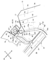
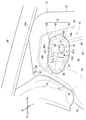
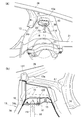
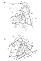
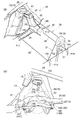
- FIG. 1 is a perspective view showing a vehicle body rear structure according to the present invention as seen obliquely from the front. It is a perspective view which shows the state which looked at the vehicle body rear part structure of FIG. 1 from diagonally back.
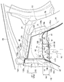
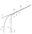
- FIG. 3 is a view on arrow 3 of FIG. 1; It is four parts enlarged view of FIG. It is a disassembled perspective view which shows the vehicle body rear part structure of FIG.
- FIG. 6 is a cross-sectional view showing a state of being broken along line 6-6 in FIG. 4; It is 7 part enlarged view of FIG. It is a perspective view which shows the wheel house and damper base of FIG. It is sectional drawing which shows the state fractured
- FIG. 8 is a cross-sectional view showing a state of being broken along line 16-16 in FIG. 7; It is a figure explaining the example which supports the load input into a damper base from the damper which concerns on this invention by a damper support part.
- the vehicle rear structure 10 according to the embodiment will be described.
- the vehicle rear portion structure 10 is a substantially symmetrical member, and the left side member and the right side member of each component constituting the vehicle rear portion structure 10 will be described with the same reference numerals.
- the vehicle body rear structure 10 includes a vehicle body frame 11 that forms a main frame of the vehicle body rear structure 10 and a pair of wheel houses 13 provided on the left and right sides of the vehicle body frame 11 in the vehicle width direction. And a damper base 15 provided in the interior 14 of the wheel house 13, a damper 16 (see FIG. 3 for the damper 16 on the left side) attached to the damper base 15, and a reinforcing leg 17 provided on the wheel house 13.
- the inside 14 of the wheel house 13 is a storage portion of the damper 16 on the outer side 29 of the wheel house 13.
- the inside 14 of the wheel house 13 is referred to as a "house space 14".
- the vehicle body frame 11 includes a pair of rear frames 21 provided on the left and right sides in the vehicle width direction, a floor panel 22 provided between the pair of rear frames 21, and a subframe 23 provided below the pair of rear frames 21 (see FIG. 3), the rear bulkhead 24 interposed between the pair of wheel houses 13, the rear cross member 25 disposed between the pair of reinforcing legs 17, and the upper end 13a of the pair of wheel houses 13 And a rear pillar 26.
- a triangular frame portion 31 substantially triangular in a side view is formed on the left side in the vehicle width direction by the left rear frame 21, the left reinforcing leg 17, and the left leg 45 of the rear bulkhead 24.
- a triangular frame portion 31 having a substantially triangular shape in a side view is formed on the right side in the vehicle width direction by the right rear frame 21, the right reinforcing leg 17, and the right leg 45 of the rear bulkhead 24. That is, the triangular frame portions 31 are provided on both sides in the vehicle width direction of the vehicle rear structure 10.
- the upper portion 32 of the left triangular frame portion 31 and the upper portion 32 of the right triangular frame portion 31 are connected by the upper cross member 46 of the rear bulkhead 24. Further, the front 33 of the left triangular frame 31 and the front 33 of the right triangular frame 31 are connected by the lower cross member 48 of the rear bulkhead 24. Furthermore, the rear portion 34 of the left triangular frame portion 31 and the rear portion 34 of the right triangular frame portion 31 are connected by the rear cross member 25.
- the triangular column frame 35 is formed by the left triangular frame portion 31, the right triangular frame portion 31, the upper cross member 46 of the rear bulkhead 24, the lower cross member 48 of the rear bulk head 24, and the rear cross member 25.
- the rear frame 21 is a frame member of the vehicle rear structure 10, and is formed in a closed cross section to ensure rigidity (see also FIG. 16).
- the rear frame 21 extends in the longitudinal direction of the vehicle body, and in this state, the rear frame 21 is provided along the house peripheral wall 74 of the wheel house 13.
- the rear frame 21 is provided with an overhang 38 on the outer wall 37 (see FIG. 16) on the wheel house 13 side.
- the overhanging portion 38 projects from the outer side wall 37 above the upper surface 21 a of the rear frame 21.
- the overhanging portion 38 is joined along the outer surface 74 a of the wheel house 13 (specifically, the house circumferential wall 74), and is joined to the lower end 17 a of the reinforcing leg 17.
- a floor panel 22 is provided between the pair of rear frames 21, and the floor panel 22 forms a floor of the passenger compartment 27.
- the overhanging portion 38 is projected above the floor panel 22.
- a sub-frame 23 is provided below the pair of rear frames 21.
- the left side of the sub-frame 23 is attached to the left rear frame 21, and the right side of the sub-frame 23 is attached to the right rear frame 21. Furthermore, the left and right sides of the sub-frame 23 are linked by a cross member.
- the lower end portion of the left damper 16 is supported on the left side portion of the sub-frame 23.
- the lower end portion of the right damper 16 is supported on the right side portion of the sub-frame 23.
- the mounting bracket 41 at the upper end is attached to the damper support 18 (described later), and the left rear wheel 42 is supported at the lower end.
- the right damper 16 has a mounting bracket at the upper end attached to the damper support 18 (not shown), and the right rear wheel 42 is supported at the lower end.
- a rear bulkhead 24 is interposed between the pair of wheel houses 13. Further, the left end of the rear bulkhead 24 is joined to the left wheel house 13, and the right end of the rear bulkhead 24 is joined to the right wheelhouse 13. Furthermore, the rear bulkheads 24 are directed to the pair of rear frames 21 and inclined downward toward the front of the vehicle body. In this state, the rear bulkhead 24 divides the space into a compartment 27 and a rear luggage compartment 28.
- the rear bulkhead 24 is a substantially rectangular frame-shaped member that divides the vehicle compartment 27 and the rear luggage compartment 28.
- the rear bulkhead 24 comprises a pair of leg portions 45 respectively joined to the wheel houses 13 on both sides in the vehicle width direction, an upper cross member 46 connecting the upper end portions 45a of the pair of leg portions 45, and a pair And a lower cross member 48 connecting the lower end 45b of the leg 45 of
- the upper end 45 a of the leg 45 is a portion included in the upper portion 32 of the triangular frame 31.
- the lower end 45 b of the leg 45 is a portion included in the front portion 33 of the triangular frame 31.
- the upper cross member 46 is formed in a substantially rectangular closed cross section, is connected to the upper end 45 a of the pair of legs 45, and is connected to the upper end 13 a of the pair of wheel houses 13.
- a rear parcel 52 is integrally provided from the upper cross member 46 toward the rear of the vehicle body, and the rear parcel 52 separates the vehicle compartment 27 from the rear luggage compartment 28.
- the lower cross member 48 is connected to the lower end 45 b of the pair of legs 45 (that is, the front 33 of the pair of triangular frames 31). In this state, the lower cross member 48 is provided below the upper cross member 46 and on the front side of the upper cross member 46 in the vehicle body.
- the rear bulkhead 24 is annularly formed (in detail, in the form of a rectangular frame) by the pair of legs 45, the upper cross member 46 and the lower cross member 48.
- the pair of legs 45, the upper cross member 46, and the lower cross member 48 are highly rigid frame members.
- an annular skeleton of the vehicle rear structure 10 is formed by the rear bulkhead 24.
- a bulkhead opening (opening) 51 is formed inside the rear bulkhead 24.
- the upper end portion 45 a of the left leg 45 crosses the left end portion 47 of the upper cross member 46 to form the left upper corner portion 53.
- the upper end 45 a of the right leg 45 crosses the right end 47 of the upper cross member 46 to form the right upper corner 53.
- the lower end 45b of the left leg 45 (that is, the front 33 of the triangular frame 31) intersects the left end 49 of the lower cross member 48, whereby the left lower corner 54 is formed.
- the lower end 45b of the right leg 45 (that is, the front 33 of the triangular frame 31) intersects the right end 49 of the lower cross member 48 to form the lower corner 54 on the right.
- the load F1 input from the left damper 16 is transmitted to the left leg 45, and transmitted from the left leg 45 to the left upper corner 53 and the left lower corner 54.
- the load input from the right damper 16 (see FIG. 2) is transmitted to the right leg 45 and transmitted from the right leg 45 to the right upper corner 53 and the right lower corner 54.
- the left flange joint portion 56 is made to project to the left upper corner portion 53 and the left lower corner portion 54.
- the flange joint 56 on the right side is made to project at the upper corner 53 on the right side and the lower corner 54 on the right side.
- the left side flange joint 56 and the right side flange joint 56 are symmetrical parts, and the left side flange joint 56 will be described based on FIGS. 4 to 8, and the right side flange joint 56 will be described below. I omit it. Also, the leg 45 on the left, the upper corner 53 on the left, the lower corner 54 on the left, and the flange joint 56 on the left are described as the leg 45, the upper corner 53, the lower corner 54 and the flange joint 56 Do.
- the leg portion 45 is joined to the wheel house 13 at the outer side, and is sloped downward toward the front of the vehicle from the upper end 45a to the lower end 45b.
- the upper end 45 a of the leg 45 is joined to the left end 47 of the upper cross member 46.
- the lower end 45 b of the leg 45 (the front 33 of the triangular frame 31) is joined to the left end 49 of the rear frame 21 and the lower cross member 48.
- the leg 45 is a front plate 58 joined to the wheel house 13 and a rear plate 59 disposed behind the front plate 58 on the vehicle body and joined to the wheel house 13.
- the front plate portion 58 is a plate formed in a substantially flat shape by three members of a central plate, an upper plate, and a lower plate.
- the front plate portion 58 has a front leg wall 61 facing the front of the vehicle body, an outer joint portion 62 projecting outward from the front leg wall 61 in the vehicle width direction, and a front flange 63 projecting from the front leg wall 61 to the bulkhead opening 51 Have.
- the outer joint portion 62 of the front plate portion 58 is joined to the wheel house 13 (specifically, the house peripheral wall 74), whereby the front leg wall 61 is disposed to face the front of the vehicle body.
- the front flange 63 has a central portion 63a extending linearly, an upper curved portion 63b extending in a curved shape upward from the central portion 63a, and a lower curved portion 63c extending in a curved shape downward from the central portion 63a.
- the upper curved portion 63b is a portion corresponding to the upper corner portion 53 (see FIG. 4), and is formed in a concave curve.
- the lower curved portion 63c is a portion corresponding to the lower corner portion 54 (see FIG. 4), and is formed in a concave curve.
- the front flange 63 is formed in a substantially U shape at the central portion 63a, the upper curved portion 63b and the lower curved portion 63c.
- a rear plate portion 59 is provided at the rear of the front plate portion 58 in the vehicle body.
- the rear plate portion 59 is disposed on the rear side of the front plate portion 58 in the vehicle body and has an inner leg wall 65 and a rear leg wall 66 formed in a substantially L-shaped cross section, and an outer joint projecting from the rear leg wall 66 to the rear of the vehicle body And a rear flange 68 projecting from the inner leg wall 65 to the bulkhead opening 51.
- the outside joint portion 62 of the rear plate portion 59 is joined to the house peripheral wall 74 of the wheel house 13, and the rear flange 68 is joined to the front flange 63 from the vehicle rear side.
- a rear leg wall 66 is spaced apart from the front leg wall 61 at the rear of the vehicle body, and extends in the vertical direction along the front leg wall 61.
- the inner leg wall 65 is disposed at an interval inward in the vehicle width direction of the wheel house 13 (specifically, the house peripheral wall 74), and extends in a substantially U shape along the front flange 63 .
- the rear flange 68 like the front flange 63, has a central portion 63a extending in a straight line, an upper curved portion 63b extending in a curved shape upward from the central portion 63a, and a lower curved portion extending in a curved shape downward from the central portion 63a. And 63c.
- the rear flange 68 is formed in a substantially U shape along the front flange 63 at the central portion 63a, the upper curved portion 63b and the lower curved portion 63c.
- the front flange 63 and the rear flange 68 are joined to form a flange joint 56 with the front flange 63 and the rear flange 68.
- the flange joint portion 56 is formed in a substantially U shape by being extended to the bulkhead opening 51 side and extending from the upper corner portion 53 to the lower corner portion 54.
- the flange joint 56 is extended so as to wrap around the upper corner 53 and the lower corner 54. Therefore, the upper corner portion 53 and the lower corner portion 54 are reinforced by the flange joint portion 56, and high rigidity of the upper corner portion 53 and the lower corner portion 54 is ensured.
- the load transmitted from the left damper 16 to the upper corner portion 53 can be supported by the flange joint portion 56 of the upper corner portion 53.
- the load transmitted from the left damper 16 to the lower corner portion 54 can be supported by the flange joint portion 56 of the lower corner portion 54. Therefore, in order to secure the rigidity of the upper corner portion 53 and the lower corner portion 54, it is not necessary to make the plate thickness dimensions of the front plate portion 58 and the rear plate portion 59 larger than necessary, and an increase in vehicle weight can be suppressed.
- the load F1 is input from the damper 16 to the damper base 15
- the load F2 is transmitted upward to the leg 45.
- a tensile load F 3 acts on the lower end 45 b of the leg 45 and the joint 71.
- the joint portion 71 is a portion to which the lower end portion 45 b and the rear frame 21 are joined.
- the lower end 45 b of the leg 45 and the joint 71 are portions included in the front portion 33 of the triangular frame 31.
- the lower end 45 b of the leg 45 is joined to the rear frame 21 at the joint 71 in consideration of the tensile load F 3 acting on the lower end 45 b of the leg 45 and the joint 71. . Furthermore, the lower end 45 b of the leg 45 was joined to the floor panel 22 at the joint 72. Thus, the lower end 45 b of the leg 45 is firmly connected to the rear frame 21. Thereby, the tensile load F3 transmitted to the leg 45 is transmitted to the rear frame 21 and is suitably supported by the rear frame 21.
- the tensile load F3 is transmitted to the lower end 45b of the leg 45 via the flange joint 56.
- the flange joint portion 56 is curved and deformed at the lower corner portion 54 inward in the vehicle width direction (i.e., the compartment 27 and the rear luggage compartment 28). Therefore, the tensile load F3 acting on the lower end 45b of the leg 45 is transmitted to the floor panel 22 through the flange joint 56 and the lower end 58a of the front plate 58. Therefore, the lower end portion 58 a of the front plate portion 58 is joined to the floor panel 22 at the joining portion 72.
- the tensile load F2 transmitted to the leg 45 can be transmitted to the rear frame 21 and suitably supported by the rear frame 21.
- the leg portion 45 is joined to the house peripheral wall 74 of the wheel house 13 and is formed in a closed cross section together with the house peripheral wall 74.
- the outer joint portion 62 of the front plate portion 58 and the outer joint portion 67 of the rear plate portion 59 are joined to the house peripheral wall 74 of the wheel house 13.
- the front flange 63 and the rear flange 68 are joined.
- a closed cross section is formed by the front leg wall 61, the inner leg wall 65, the rear leg wall 66, and the house peripheral wall 74 of the wheel house 13. That is, a closed cross section is formed by the leg 45 and the house peripheral wall 74, and the rigidity of the leg 45 is enhanced.
- the intersection 69 of the inner leg wall 65 and the rear leg wall 66 is formed in a ridge shape projecting outward.
- the “intersection 69” is referred to as “the ridge 69”.
- the rigidity of the ridge portion 69 is enhanced by the ridge portion 69 protruding outward, and the rigidity of the left leg 45 is enhanced by the ridge portion 69.
- the rear cross member 25 is disposed at the rear of the lower cross member 48 in the vehicle body and between the lower end 17 a of the left reinforcing leg 17 and the lower end 17 a of the right reinforcing leg 17.
- the lower end portion 17 a of the reinforcing leg portion 17 is a portion included in the rear portion 34 of the triangular frame portion 31.
- the rear cross member 25 extends in the vehicle width direction between the lower end 17a on the left side and the lower end 17a on the right side, and spans over the left rear frame 21 and the right rear frame 21.
- the overhanging portion 38 of the rear frame 21 is joined to the lower end portion 17 a of the reinforcing leg portion 17.
- the lower end 17a of the left reinforcing leg 17 is connected to the left rear frame 21.
- the lower end portion 17 a of the right reinforcing leg 17 is connected to the right rear frame 21.
- the left end 25a of the rear cross member 25 is connected to the lower end 17a of the left reinforcing leg 17 via the left rear frame 21.
- the right end 25a of the rear cross member 25 is connected to the lower end 17a of the right reinforcing leg 17 via the right rear frame 21.
- wheel houses 13 are provided on both sides in the vehicle width direction of the rear bulkhead 24.
- the left wheel house 13 is a rear wheel house joined to the left side portion of the rear bulkhead 24 and having a lower end portion 13 b joined to the left rear frame 21.
- the left damper 16 (see FIG. 3) is disposed on the house space 14 side of the left wheel house 13.
- the left damper 16 supports the left rear wheel 42 and the left rear wheel 42 is covered by the left wheel house 13.
- the wheel house 13 on the right side is a rear wheel house joined to the right side portion of the rear bulkhead 24 and having the lower end portion 13 b joined to the rear frame 21 on the right side, similarly to the wheel house 13 on the left side.
- the right damper 16 is disposed on the house space 14 side of the right wheel house 13.
- the right damper 16 supports the right rear wheel 42 and the right rear wheel 42 is covered by the right wheel house 13.
- the wheel house 13 on the left side and the wheel house 13 on the right side are symmetrical parts, and hereinafter, the wheel house 13 on the left side will be described, and the description of the wheel house 13 on the right side will be omitted.
- the wheel house 13 includes a house peripheral wall 74 forming a peripheral wall of the wheel house 13, a house top portion 75 closing the upper end 74 b of the house peripheral wall 74, a house peripheral wall 74 and a house top 75 And a house overhanging portion 76 projecting outward. Further, the left wheel house 13 has an opening 77 (see also FIG. 6) open toward the outside in the vehicle width direction.
- the house peripheral wall 74 is formed in a substantially U-shaped cross section so as to cover the left rear wheel 42 from the side of the compartment 27.
- the house peripheral wall 74 includes a house front wall 81 (see FIG. 6), a house rear wall 82, a house side wall 83, a house front corner ridge portion 84, and a house rear corner ridge portion (house corner ridge portion) 85. .
- the house front wall 81 is provided on the front surface 42 a side of the left rear wheel 42, and the surface is disposed to face the front of the vehicle body.
- a house rear wall 82 is disposed at the rear of the vehicle body of the house front wall 81.
- the house rear wall 82 is provided on the rear surface 42b side of the left rear wheel 42, and the surface is disposed to face the rear of the vehicle body.
- the house rear wall 82 is inclined downward to the rear of the vehicle body from the upper end 82a to the left rear frame 21 to the lower end 82b (see also FIG. 8).
- a house sidewall 83 is formed between the inside of the house front wall 81 and the inside of the house rear wall 82.
- the house side wall 83 extends in the longitudinal direction of the vehicle body, and the surface is disposed to face the rear luggage compartment 28 (that is, the inner side in the vehicle width direction).
- a house rear corner ridge 85 is formed at the intersection of the rear end of the house side wall 83 and the outer side of the house rear wall 82.
- the house rear corner ridge portion 85 is formed in a ridge line shape with high rigidity by projecting inward in the vehicle width direction.
- the house rear corner ridge portion 85 extends from the upper end portion 85a on the house top portion 75 side toward the left rear frame 21 so as to incline downward to the rear of the vehicle body from the lower end portion 85b.
- a house front corner ridge 84 is formed at the intersection of the front end of the house side wall 83 and the outer side of the house front wall 81. Similar to the house rear corner ridge portion 85, the house front corner ridge portion 84 is formed in a ridge shape having high rigidity by projecting inward in the vehicle width direction.
- a house peripheral wall 74 is formed in a substantially U-shaped cross section by the house front wall 81, the house front corner ridge portion 84, the house side wall 83, the house rear corner ridge portion 85, and the house rear wall 82 (see also FIG. 10).
- a house top 75 is formed at an upper end 74 b of the house peripheral wall 74.
- the house top 75 is formed on the upper end 74 b of the house peripheral wall 74, whereby the upper end 74 b of the house peripheral wall 74 is closed by the house top 75.
- the house top 75 has a horizontal top 87 formed substantially horizontally, and an inclined top 88 extending upward from the outer side 87a of the horizontal top 87 outward in the vehicle width direction.
- a house space 14 is formed on the outer side 29 of the wheel house 13 by forming the house peripheral wall 74 in a substantially U-shaped cross section in the wheel house 13.
- the house space 14 is separated from the rear luggage compartment 28 by the wheel house 13.
- a damper 16 and a rear wheel 42 are disposed on the house space 14 side.
- a damper base 15 is provided in the house space 14 on the outer side 29 of the wheel house 13 and on the outer side 29 of the rear bulkhead 24.
- the damper base 15 includes a damper mounting portion 91 disposed below the top portion 75 of the house in the housing space 14, a support wall 92 raised upward from the damper mounting portion 91, and the damper mounting portion 91 and the support wall 92. And a peripheral flange 93 formed along.
- the damper mounting portion 91 includes a first flat portion 95 disposed substantially parallel to the house top 75, a second flat portion 96 disposed above the first flat portion 95, a first flat portion 95, and a first flat portion 95. And an inclined portion 97 connecting the two flat portions 96.
- the first flat portion 95 of the damper mounting portion 91 is disposed between the rear corner flange portion 85 and the leg 45 of the house peripheral wall 74 in the longitudinal direction of the vehicle body.
- the damper mounting portion 91 is formed in a step-like shape by the first flat portion 95, the second flat portion 96, and the inclined portion 97, and the rigidity of the damper mounting portion 91 is secured.
- a damper fitting opening 98 is formed substantially at the center of the first flat portion 95. Therefore, the damper fitting opening 98 is disposed between the rear corner flange portion 85 and the leg 45 of the house peripheral wall 74 in the front-rear direction of the vehicle body. Furthermore, in the first flat portion 95, a front attachment hole 101 and a rear attachment hole 102 are formed in the vicinity of the peripheral edge of the damper fitting opening 98.
- the front mounting hole 101 is located in front of the vehicle and on the inner side in the vehicle width direction.
- the rear mounting hole 102 is located at the rear of the vehicle body and on the outer side in the vehicle width direction.
- the support wall portion 92 is raised upward from the outer side portion 91 a of the damper mounting portion 91 toward the house top portion 75.
- the outer side portion 91 a of the damper mounting portion 91 is a side portion of the damper mounting portion 91 on the side of the opening portion 77 of the wheel house 13 (in other words, the opposite side of the house side wall 83).
- the support wall 92 is raised upward from the outer side portion 91 a of the damper mounting portion 91, whereby the damper base 15 is formed in a substantially L-shaped cross section by the damper mounting portion 91 and the support wall 92. Thereby, the damper mounting portion 91 is reinforced by the support wall portion 92, and the rigidity of the damper mounting portion 91 is further secured.
- a peripheral flange 93 is formed endlessly (in other words, annular) along the outer periphery 91 b of the damper mounting portion 91 and the outer periphery 92 a of the support wall 92.
- the peripheral flange 93 is joined to the inner surface of the upper end 74 b of the house peripheral wall 74 and the inner surface of the house top 75.
- the damper support 18 is formed by the damper base 15, the upper end 74 b of the house peripheral wall 74, and the house top 75.
- the peripheral flange 93 is joined to the inner surface of the upper end portion 74b of the house peripheral wall 74 and the inner surface of the house top portion 75, whereby the entire periphery of the damper base 15 is kept closed.
- the damper support portion 18 is formed in a bag shape (box shape) by the damper base 15, the upper end portion 74b of the house peripheral wall 74, and the house top portion 75 (see also FIGS. 9 and 13).
- a bag shape By forming the damper support portion 18 in a bag shape, high rigidity of the damper support portion 18 is ensured.
- the damper support portion 18 with high rigidity can be easily formed, and the configuration can be simplified.
- a bulkhead 105 is provided substantially at the center in the longitudinal direction of the vehicle body in the interior 19 (see FIGS. 9 and 13) of the damper support portion 18.
- the bulkhead 105 is provided with a lower flange (lower end) 107 joined to the damper mounting portion 91 and the support wall 92, an upright wall 108 raised upward from the lower flange 107, and an upper end of the upright wall 108 And an upper flange (upper end) 109 to be taken out.
- the upper flange 109 is joined to the house top 75.
- the mounting hole 111 is formed in the inner end portion 107 a of the lower flange 107.
- the mounting hole 111 of the lower flange 107 is disposed at a position corresponding to the front mounting hole 101 of the damper mounting portion 91.
- the mounting bracket 41 of the damper 16 is attached to the damper support portion 18 (see FIG. 13) using the attachment hole 111, the front attachment hole 101, and the rear attachment hole 102.
- the front mounting hole 113 and the rear mounting hole 114 are formed in the mounting bracket 41 of the damper 16.
- a bolt 116 is inserted into the front mounting hole 113 of the mounting bracket 41, the front mounting hole 101 of the first flat portion 95, and the mounting hole 111 of the lower flange 107, and the nut 117 is screwed to the bolt 116.
- a bolt 116 is inserted into the rear mounting hole 114 of the mounting bracket 41 and the rear mounting hole 102 of the first flat portion 95, and the nut 117 is screwed to the bolt 116.
- the bolt 116 and the nut 117 are fastening portions.
- the upper portion 16a of the left damper 16 is fitted into the damper fitting opening 98, and the mounting bracket 41 of the left damper 16 is fastened to the first flat portion 95 (that is, the damper mounting portion 91). .
- the damper 16 is connected to the highly rigid damper support portion 18 and disposed on the outer side 29 of the wheel house 13.
- the mounting bracket 41 of the damper 16 is disposed between the rear rear flange portion 85 (see FIG. 11) and the leg 45 of the peripheral wall 74 in the longitudinal direction of the vehicle body.
- bolts 116 are inserted into the front mounting holes 113 of the mounting bracket 41, the front mounting holes 101 of the first flat portion 95, and the mounting holes 111 of the lower flange 107, and the nuts 117 are screwed to the bolts 116. . That is, the lower flange 107 of the bulkhead 105 is fastened to the damper attachment portion 91 by the bolt 116 and the nut 117 for attaching the damper 16 to the attachment bracket 41. Accordingly, the load F1 input from the damper 16 to the damper mounting portion 91 is transmitted to the bulkhead 105 through the bolt 116 and the nut 117.
- the lower flange 107 of the bulkhead 105 is joined to the damper attachment portion 91 and the support wall portion 92. Further, the upper flange 109 of the bulkhead 105 is joined to the house top 75.
- the load input from the damper 16 to the damper attachment portion 91 that is, the damper base 15
- the load F1 input from the damper 16 to the damper base 15 can be suitably supported by the damper support portion 18, and the deformation of the damper attachment portion 91 can be suppressed.
- the height H ⁇ b> 2 of the damper attachment portion 91 is adjusted by changing the height dimension H ⁇ b> 1 of the support wall portion 92. Therefore, by changing the height dimension H1 of the support wall 92, the height of the damper mounting portion 91 can be adjusted according to the height dimensions (that is, the length dimensions) of the various dampers 16. As a result, it becomes possible to make the damper support 18 correspond to various types of dampers 16, and the application of the damper support 18 can be expanded.
- the damper support 18 is connected to the upper end 45 a of the rear bulkhead 24 (specifically, the leg 45).
- the damper support portion 18 is formed by the damper base 15, the upper end portion 74 b of the house peripheral wall 74, and the house top portion 75.
- the upper end portion 45a of the leg portion 45 (that is, the upper end portion of the front plate portion 58 and the upper end portion of the rear plate portion 59) is joined to the upper end portion 74b of the house peripheral wall 74.
- the damper base 15 is joined to the upper end 45 a of the leg 45 via the upper end 74 b of the house peripheral wall 74.
- the upper end portion 74 b of the house peripheral wall 74 includes the upper end portion 85 a of the rear rear corner flange portion 85.
- the damper base 15 is joined to the upper end portion 85 a of the rear rear corner flange portion 85.
- the leg 45 is inclined downward from the upper end 45 a to the lower end 45 b toward the front of the vehicle body.
- the house rear corner ridge portion 85 is inclined downward toward the rear of the vehicle body from the upper end portion 85a to the lower end portion 85b. Therefore, as the house rear corner ridge portion 85 and the leg portion 45 go from the damper support portion 18 toward the rear frame 21, the space in the vehicle longitudinal direction is extended gradually. That is, the house rear corner ridge portion 85 and the leg portion 45 are provided in an inverted V shape in a side view.
- the damper support 18 is connected to the rear frame 21 via the legs 45.
- the lower end portion 85 b of the house rear corner ridge portion 85 is connected to the overhang portion 38 of the rear frame 21.
- the damper support portion 18 is connected to the rear frame 21 through the house rear corner flange portion 85.
- the rigidity of the rear rear corner hook portion 85, the leg 45, and the rear frame 21 is secured high.
- the damper support portion 18 is supported in a stable state by the rear rear corner hook portion 85, the leg 45, and the rear frame 21.
- the reinforcing legs 17 are provided so as to straddle the house rear corner ridge portion 85 from the outside of the house peripheral wall 74.
- the reinforcing legs 17 extend in the vertical direction along the house rear corner ridge 85.
- the reinforcing leg 17 has an apex 121 facing the house rear corner ridge 85, an inner wall 122 and an outer wall 123 formed on the apex 121, and an inner flange formed on the inner wall 122. And an outer flange 125 formed on the outer wall 123.
- the inner wall 122 projects from the inner end of the top 121 toward the house sidewall 83.
- the outer wall 123 projects from the outer end of the top 121 toward the house rear wall 82.
- the inner flange 124 projects from the side end of the inner wall 122 along the house side wall 83 toward the front of the vehicle body.
- the outer flange 125 projects from the side end of the outer wall 123 along the house rear wall 82 outward in the vehicle width direction.
- the top portion 121, the inner wall 122 and the outer wall 123 are formed in a substantially U-shaped cross section.
- the reinforcing leg portion 17 is formed in a hat-like shape in cross section by the top portion 121, the inner wall 122, the outer wall 123, the inner flange 124 and the outer flange 125.
- the inner flange 124 is joined to the house side wall 83 and the outer flange 125 is joined to the house rear wall 82 in a state where the top 121 is opposed to the house rear corner ridge 85.
- the upper end 17 b of the reinforcing leg 17 is joined to the upper end 74 b of the house peripheral wall 74.
- the lower end portion 17 a of the reinforcing leg portion 17 is joined to the lower end portion 74 c of the house peripheral wall 74.
- the reinforcing leg portion 17 is joined to the house peripheral wall 74 so as to straddle the house rear corner ridge portion 85.
- the reinforcing leg 17 is directed from the rear frame 21 along the house rear corner ridge portion 85 toward the left end 47 (see FIG. 7) of the rear bulkhead 24 (specifically, the upper cross member 46). It is extended upward.
- the upper cross member 46 is formed of a front member 127 and a rear member 128 in a substantially rectangular closed cross section. Further, the left end portion 47 of the upper cross member 46 includes a front bracket 131 extended outward from the front member 127 in the vehicle width direction, and a rear bracket 132 joined to the rear of the front bracket 131 in the vehicle body. The left end portion 47 of the upper cross member 46 is formed into a box shape having a substantially U-shaped cross section by the front bracket 131 and the rear bracket 132.
- the front bracket 131 has a front wall 134 protruding upward from the upper end 81 a of the house front wall 81 and a top 135 bent from the upper end of the front wall 134 to the rear of the vehicle body.
- the front bracket 131 is formed in a substantially V-shaped cross section by the front wall 134 and the top portion 135.
- the lower end portion of the front wall 134 is joined to the upper end portion 81 a of the house front wall 81, and the flange 134 a of the front wall 134 is joined to the house overhang portion 76 of the wheel house 13.
- the flange 135 a of the top portion 135 is joined to the house overhang portion 76.
- the rear end 135 b of the top 135 is joined to the upper end 132 a of the rear bracket 132.
- the rear bracket 132 has a rear wall 137 projecting upward from the upper end 82 a of the house rear wall 82 and a side wall 138 bent from the inner side of the rear wall 137 along the house side wall 83 to the front of the vehicle body.
- the lower end portion of the rear wall 137 is joined to the upper end portion 82 a of the house rear wall 82, and the flange 137 a of the rear wall 137 is joined to the house overhang portion 76 of the wheel house 13.
- the lower end of the side wall 138 is joined to the upper end 83 a of the house side wall 83, and the front end of the side wall 138 is joined to the upper end 45 a of the leg 45 and the rear member 128 of the upper cross member 46.
- the lower end portion of the rear wall 137 is joined to the upper end portion 82a of the house rear wall 82, and the lower end portion of the side wall 138 is joined to the upper end portion 83a of the house side wall 83.
- the front bracket 131 and the rear bracket 132 are formed to be substantially U-shaped in cross section and joined to the upper end 74 b of the house peripheral wall 74.
- the upper end portion 74 b of the house peripheral wall 74 is a portion that forms the damper support portion 18.
- the damper support 18 is reinforced by the front bracket 131 and the rear bracket 132.
- three members of the peripheral flange 93 of the damper base 15 (specifically, the damper mounting portion 91), the upper end 74b of the house peripheral wall 74, and the lower end 132b of the rear bracket 132 overlap one another. It joins in the state where it is done.
- a plurality of plate members are stacked and welded (specifically, spot welding), it is usually preferable to suppress three plate members to be stacked.
- the upper end 24 a of the rear bulkhead 24 is formed at the left end 47 of the upper cross member 46.
- the rear bracket 132 is included at the left end 47 of the upper cross member 46.
- the damper base 15 is joined to the upper end 24 a of the rear bulkhead 24 via the upper end 74 b of the house peripheral wall 74.
- the rear bracket 132 (specifically, the front end of the side wall 138) is joined to the upper end 45a of the leg 45 and the left end 128a of the upper cross member 46 (specifically, the rear member 128).
- the three members ie, the peripheral flange 93 of the damper base 15 (the damper mounting portion 91), the upper end 74b of the house peripheral wall 74, and the lower end 132b of the rear bracket 132, are joined together. Further, the three members of the upper end 17b of the reinforcing leg 17, the upper end 74b of the house peripheral wall 74, and the lower end 132b of the rear bracket 132 are joined in a superimposed state.
- the damper base 15 is joined to the reinforcing leg 17 via the upper end 74 b of the house peripheral wall 74 and the lower end 132 b of the rear bracket 132 (that is, the upper end 24 a of the rear bulkhead 24).
- the damper base 15 is not welded to the four members by welding (spot welding) by overlapping the upper end 74b of the house peripheral wall 74, the lower end 132b of the rear bracket 132, and the reinforcement leg 17 on the damper base 15. It can be joined to the reinforcing legs 17. Thereby, joining operation which joins damper base 15 to reinforcement leg 17 can be made easy.
- the lower end 17 a of the reinforcing leg 17 is joined to the lower end 74 c of the house peripheral wall 74. Furthermore, the overhanging portion 38 of the rear frame 21 is joined to the lower end portion 17 a of the reinforcing leg portion 17. That is, the lower end portion 17 a of the reinforcing leg portion 17 is joined to the rear frame 21. Further, the upper end 17 b of the reinforcing leg 17 is joined to the upper end 74 b of the house peripheral wall 74. Furthermore, the upper end portion 17 b of the reinforcing leg portion 17 is joined to the upper end portion 45 a of the leg portion 45 via the side wall 138 of the rear bracket 132.
- the reinforcing leg portion 17 is provided so as to straddle the rear rear corner ridge portion 85 (see also FIG. 8) from the outer side (i.e., the rear luggage compartment 28 side) of the wheel house 13. Therefore, the rigidity of the rear rear corner ridge portion 85 can be further secured by the reinforcing leg portion 17, and the relatively large load can be supported by the rear rear corner ridge portion 85 and the reinforcement leg portion 17. As a result, for example, a relatively large load can be supported without increasing the thickness of the wheel house 13 more than necessary, and the increase in vehicle weight can be favorably suppressed.
- the reinforcing leg 17 is joined to the house peripheral wall 74, and the upper end 45 a of the leg 45 and the rear frame 21 are connected by the reinforcing leg 17 by the reinforcing leg 17. Thereby, the rigidity of the rear bulkhead 24, the rear frame 21 and the wheel house 13 (that is, the rigidity of the vehicle rear structure 10) is secured high.
- a reinforcing leg 17 is provided so as to straddle the house rear corner ridge 85.
- the reinforcing leg portion 17 and the house rear corner ridge portion 85 will be described as “the rear leg portion 86”.
- the damper support portion 18 is supported in a stable state by the rear leg 86, the leg 45, and the rear frame 21. In this state, the mounting bracket 41 (see FIG. 3) of the damper 16 is disposed between the rear leg 86 and the leg 45 in the longitudinal direction of the vehicle body.
- the damper 16 transmits a load F1 (see FIG. 3) to the damper support 18.
- the load F1 transmitted to the damper support 18 is suitably transmitted as a tensile load to the rear frame 21 through the rear leg 86 and the leg 45.
- the tensile load transmitted to the rear frame 21 is supported by the rear frame 21.
- the rear bulkhead 24 is a member generally used in a vehicle provided with the passenger compartment 27 and the rear luggage compartment 28.
- the legs 45 of the rear bulkhead 24 can be used also as a member forming an inverted V-shape. Thereby, it is not necessary to provide a dedicated member for forming an inverted V-shape, and an increase in vehicle weight can be favorably suppressed.
- the rear bulkhead 24 is formed in a rectangular frame shape by the left leg 45, the right leg 45, the upper cross member 46 and the lower cross member 48. Further, each member 45, 45, 46, 48 is formed in a closed cross-sectional shape, and is provided with a ridged portion. Therefore, the load transmitted to the legs 45 can be transmitted to the rectangular bulky rear bulkhead 24 (in particular, a ridge-like portion), and the rear bulkhead 24 can support the load. As a result, torsional deformation (in particular, torsional deformation of the vehicle rear structure 10 in the vertical direction) is generated in the vehicle rear structure 10 by the load F1 input to the damper support 18 from the damper 16 (see FIG. 3). It is possible to suppress and improve the steering stability.
- connection brace 141 is raised from the top portion 135 of the left end portion 47 of the upper cross member 46 toward the rear pillar 26. Therefore, the left end portion 47 of the upper cross member 46 and the rear pillar 26 are connected by the connection brace 141. Thereby, when the load F1 is transmitted from the damper 16 to the damper support portion 18, the transmitted load F1 is transmitted to the rear pillar 26 through the left end portion 47 of the upper cross member 46 and the connection brace 141.
- the rear pillar 26 is a highly rigid member formed in a closed cross section. Therefore, the load transmitted from the connection brace 141 to the rear pillar 26 is suitably supported by the rear pillar 26. Thereby, the load F1 transmitted from the damper 16 to the damper support 18 can be supported in a state where the plate thickness dimension of the damper support 18 (particularly, the damper base 15) is suppressed.
- the sub-frame 23 is provided below the left rear frame 21 and the right rear frame 21. Specifically, the front attachment portion 147 of the left side portion of the sub frame 23 is connected to the front attachment portion 144 of the left rear frame 21 by a bolt 151. Further, the rear mounting portion 148 of the left side portion of the sub frame 23 is connected to the rear mounting portion 145 of the left rear frame 21 by a bolt 151. Similarly, the front mounting portion 147 of the right side portion of the sub frame 23 is connected to the front mounting portion 144 of the right rear frame 21 by a bolt 151. Further, the rear attachment portion 148 of the right side portion of the sub frame 23 is connected to the rear attachment portion 145 of the right rear frame 21 by a bolt 151.
- the left damper 16 is supported on the left side of the sub-frame 23.
- the right damper 16 is supported on the right side of the sub-frame 23.
- the load input from the left damper 16 to the left side of the sub frame 23 is transmitted to the front mounting portion 144 and the rear mounting portion 145 of the left rear frame 21 as a load F4 and a load F5.
- the load input from the right damper 16 to the right side of the sub frame 23 is transmitted to the front mounting portion 144 and the rear mounting portion 145 of the right rear frame 21 as a load F6 and a load F7.
- front attachment portion 144 and the rear attachment portion 145 of the left rear frame 21 are provided at portions adjacent to the front portion 33 and the rear portion 34 of the left triangular frame portion 31.
- front attachment portion 144 and the rear attachment portion 145 of the right rear frame 21 are provided at portions adjacent to the front portion 33 and the rear portion 34 of the right triangular frame portion 31.
- the left triangular frame portion 31 is formed with high rigidity by the left rear frame 21, the left rear leg 86 and the left leg 45.
- the right triangular frame portion 31 is formed with high rigidity by the right rear frame 21, the right rear leg 86, and the right leg 45.
- the triangular frame 31 is formed by connecting the triangular frame 31 on the left side and the triangular frame 31 on the right side by the upper cross member 46 of the rear bulk head 24 and the lower cross member 48 of the rear bulk head 24 and the rear cross member 25. Is formed.
- the triangular prism frame 35 is a portion with high rigidity.
- the left damper support 18 is provided on the upper portion 32 of the left triangular frame 31. Further, the damper support portion 18 on the right side is provided on the upper portion 32 of the triangular frame portion 31 on the right side.
- the left damper support 18 and the right damper support 18 are bag-shaped high-rigidity parts. Therefore, the triangular column frame 35 is reinforced by the left damper support 18 and the right damper support 18. Since the triangular column frame body 35 is reinforced by the left damper support 18 and the right damper support 18, high rigidity can be ensured while suppressing an increase in weight of the vehicle rear structure 10.
- the loads F4 and F5 transmitted from the left side of the sub-frame 23 (see FIG. 3) to the front mounting portion 144 and the rear mounting portion 145 of the left rear frame 21 Can support.
- the loads F6 and F7 transmitted from the right side of the sub-frame 23 to the front attachment portion 144 and the rear attachment portion 145 of the right rear frame 21 can be supported by the right triangular frame portion 31 or triangular column frame 35 .
- the left damper support 18 is provided on the upper portion 32 of the left triangular frame 31, and the right damper support 18 is provided on the upper portion 32 of the right triangular frame 31. Therefore, the triangular column frame 35 is reinforced by the left damper support 18 and the right damper support 18.
- the load F1 (see FIG. 3) transmitted from the left damper 16 to the left damper support 18 and the load F1 transmitted from the right damper 16 to the right damper support 18 are It can be well supported.
- the damper base 15 is provided in the house space 14 of the wheel house 13, and the mounting bracket 41 of the damper 16 is attached to the damper base 15. Therefore, for example, in the state of vehicle travel, the load F8 is input from the damper 16 to the damper attachment portion 91.
- the damper base 15 is formed on a bag-like damper support 18 together with an upper end 74b of a house peripheral wall 74 and a house top 75. Furthermore, a bulkhead 105 is provided inside the damper support 18. Therefore, the rigidity of the damper support portion 18 is secured high. Thereby, the load F8 input from the damper 16 to the damper base 15 can be suitably supported by the damper support portion 18.
- the load F ⁇ b> 8 input to the damper base 15 is supported by the damper support 18.
- the load F8 transmitted to the damper support 18 is transmitted to the leg 45 (see FIG. 18 (a)) as the tensile load F9, and to the rear leg 86 (see FIG. 18 (b)) as the tensile load F10. It is transmitted.
- the compressive load F11 acts on the upper corner portion 53
- the tensile load F12 acts on the lower corner portion 54.
- the flange joint portion 56 of the leg portion 45 extends from the upper corner portion 53 to the lower corner portion 54, and the rigidity of the upper corner portion 53 and the lower corner portion 54 is secured by the flange joint portion 56.
- the compressive load F11 transmitted to the upper corner portion 53 can be supported by the flange joint portion 56 of the upper corner portion 53.
- the tensile load F12 transmitted to the lower corner portion 54 can be supported by the flange joint portion of the lower corner portion 54.
- the tensile load F9 transmitted to the leg 45 is transmitted to the rear frame 21 through the leg 45. Further, the tensile load F ⁇ b> 10 transmitted to the rear leg 86 is transmitted to the rear frame 21 through the rear leg 86.
- the rear frame 21 is a rigid frame member extending in the longitudinal direction of the vehicle body, and the transmitted tensile load is suitably supported by the rear frame 21.
- the loads F11 to F14 input from the sub-frame 23 to the rear frame 21 are supported by the triangular column frame 35
- the upper portion 32 of the left triangular frame portion 31 is reinforced by the left damper support portion 18, and the upper portion 32 of the right triangular frame portion 31 is reinforced by the right damper support portion 18 There is.
- the triangular column frame 35 is reinforced by the left damper support 18 and the right damper support 18.
- the front attachment portion 147 of the left side of the sub frame 23 is attached to the left rear frame 21.
- the load F11 is transmitted to the part 144.
- the load F12 is transmitted from the rear attachment portion 148 on the left side of the sub-frame 23 to the rear attachment portion 145 on the left rear frame 21.
- the load F13 is transmitted from the front attachment portion 147 on the right side of the sub frame 23 to the front attachment portion 144 on the right rear frame 21.
- the load F14 is transmitted from the rear attachment portion 148 on the right side of the sub-frame 23 to the rear attachment portion 145 on the right rear frame 21.
- the load F11 and the load F12 transmitted to the left rear frame 21 are supported by the triangular column frame 35 (in particular, the left triangular frame portion 31). Further, the load F13 and the load F14 transmitted to the right rear frame 21 are supported by the triangular column frame body 35 (in particular, the triangular frame portion 31 on the right side).
- the triangular column frame body 35 in particular, the triangular frame portion 31 on the right side.
- the triangular column frame body 35 is reinforced by the left damper support 18 and the right damper support 18.
- the load F8 transmitted from the left damper 16 (see FIG. 19B) to the left damper support 18 can be supported well by the triangular column frame 35 (particularly, the left triangular frame 31).
- the load F8 transmitted from the right damper 16 to the right damper support 18 can be favorably supported by the triangular column frame 35 (in particular, the right triangular frame 31).
- the rear structure of the vehicle body according to the present invention is not limited to the above-described embodiment, and appropriate changes, improvements and the like can be made.
- the example which provides the reinforcement leg 17 so that it straddles the house rear corner ridge part 85 of the wheel house 13 was demonstrated in the said Example, it is not restricted to this, and it is set as the structure which does not provide the reinforcement leg 17. Is also possible.
- the house rear corner ridge 85 and the left leg 45 are provided in an inverted V shape in a side view. Therefore, the damper support portion 18 is supported in a stable state by the rear rear corner hook portion 85, the left leg 45 and the rear frame 21.
- the load transmitted from the damper 16 to the damper support 18 is transmitted as a tensile load to the rear frame 21 through the rear rear corner flange 85 and the leg 45.
- the tensile load transmitted to the rear frame 21 is suitably supported by the rear frame 21.
- the lower flange 107 of the bulkhead 105 is fastened to the mounting bracket 41 and the damper base 15 of the damper 16 by the bolt 116 and the nut 117.
- the present invention is not limited to this.
- the same effect can be obtained by providing the bulkhead 105 in the vicinity of the bolt 116 and the nut 117 for fastening the mounting bracket 41 of the damper 16 and the damper base 15.
- the load input from the damper 16 to the damper base 15 can be transmitted to the support wall 92 and the house top 75 through the bulkhead 105 as in the embodiment.
- the load input to the damper base 15 can be suitably supported by the damper support portion 18, and the deformation of the damper base 15 can be suppressed.
- front attachment portion 144 and the rear attachment portion 145 of the rear frame 21 are provided at the portions adjacent to the front 33 and the rear 34 of the triangular frame 31 . is not.
- the front attachment portion 144 and the rear attachment portion 145 of the rear frame 21 may be vertically aligned with the front portion 33 and the rear portion 34 of the triangular frame portion 31.
- the shape and configuration of the rear leg wall, rear flange, house peripheral wall, house top, house rear corner ridge, damper mounting part, support wall, peripheral flange, bulkhead, etc. are not limited to those illustrated, and appropriate changes may be made. It is possible.
- the present invention is suitable for application to an automobile having a vehicle rear portion structure in which a wheel house is provided on a rear frame extending in the front-rear direction of the vehicle body and a damper is disposed on the outer side of the wheel house.
Landscapes
- Engineering & Computer Science (AREA)
- Chemical & Material Sciences (AREA)
- Combustion & Propulsion (AREA)
- Transportation (AREA)
- Mechanical Engineering (AREA)
- Body Structure For Vehicles (AREA)
Abstract
Priority Applications (4)
| Application Number | Priority Date | Filing Date | Title |
|---|---|---|---|
| JP2017523144A JP6402249B2 (ja) | 2015-06-08 | 2016-04-18 | 車体後部構造 |
| BR112017026152-9A BR112017026152A2 (pt) | 2015-06-08 | 2016-04-18 | estrutura de corpo traseiro de veículo |
| CN201680033289.4A CN107635860B (zh) | 2015-06-08 | 2016-04-18 | 车身后部结构 |
| US15/580,130 US10300959B2 (en) | 2015-06-08 | 2016-04-18 | Vehicle rear body structure |
Applications Claiming Priority (2)
| Application Number | Priority Date | Filing Date | Title |
|---|---|---|---|
| JP2015115880 | 2015-06-08 | ||
| JP2015-115880 | 2015-06-08 |
Publications (1)
| Publication Number | Publication Date |
|---|---|
| WO2016199499A1 true WO2016199499A1 (fr) | 2016-12-15 |
Family
ID=57503670
Family Applications (1)
| Application Number | Title | Priority Date | Filing Date |
|---|---|---|---|
| PCT/JP2016/062282 Ceased WO2016199499A1 (fr) | 2015-06-08 | 2016-04-18 | Structure pour partie arrière d'une carrosserie de véhicule |
Country Status (6)
| Country | Link |
|---|---|
| US (1) | US10300959B2 (fr) |
| JP (1) | JP6402249B2 (fr) |
| CN (1) | CN107635860B (fr) |
| BR (1) | BR112017026152A2 (fr) |
| MY (1) | MY179670A (fr) |
| WO (1) | WO2016199499A1 (fr) |
Cited By (6)
| Publication number | Priority date | Publication date | Assignee | Title |
|---|---|---|---|---|
| US20160297483A1 (en) * | 2013-09-25 | 2016-10-13 | Toyota Jidosha Kabushiki Kaisha | Vehicle rear portion structure |
| CN107901990A (zh) * | 2017-10-20 | 2018-04-13 | 宁波吉利汽车研究开发有限公司 | 一种提升后碰性能的后地板框架梁 |
| WO2019008717A1 (fr) * | 2017-07-06 | 2019-01-10 | 本田技研工業株式会社 | Structure de carrosserie de véhicule |
| WO2020261917A1 (fr) * | 2019-06-27 | 2020-12-30 | 本田技研工業株式会社 | Structure arrière de véhicule |
| US11273874B2 (en) * | 2019-04-17 | 2022-03-15 | Mazda Motor Corporation | Vehicle rear body structure |
| US20220340209A1 (en) * | 2021-04-26 | 2022-10-27 | Hyundai Motor Company | Rear body structure |
Families Citing this family (12)
| Publication number | Priority date | Publication date | Assignee | Title |
|---|---|---|---|---|
| US10279845B2 (en) * | 2015-06-08 | 2019-05-07 | Honda Motor Co., Ltd. | Vehicle rear body structure |
| US20180065683A1 (en) * | 2016-09-07 | 2018-03-08 | Thunder Power New Energy Vehicle Development Company Limited | Rear shock tower |
| JP7054652B2 (ja) * | 2018-06-26 | 2022-04-14 | 本田技研工業株式会社 | 車体リヤフロア構造 |
| DE102018126040B4 (de) * | 2018-10-19 | 2022-12-29 | Benteler Automobiltechnik Gmbh | Verbindungshülsenanordnung zum Verbinden von rohrförmigen Querträgern in einem Fahrzeug |
| JP7081533B2 (ja) * | 2019-02-27 | 2022-06-07 | マツダ株式会社 | 車両の後部車体構造 |
| US10864947B2 (en) * | 2019-03-27 | 2020-12-15 | Honda Motor Co., Ltd. | Rear support structure for a vehicle |
| US10967913B2 (en) * | 2019-08-28 | 2021-04-06 | Ford Global Technologies, Llc | Detachable quarter panel bracket |
| KR20220085231A (ko) * | 2020-12-15 | 2022-06-22 | 현대자동차주식회사 | 후방 차체 구조 |
| CN115140180B (zh) * | 2021-03-31 | 2024-10-18 | 本田技研工业株式会社 | 车身后部结构 |
| CN115214787B (zh) * | 2022-03-14 | 2023-09-29 | 广州汽车集团股份有限公司 | 车身后部结构和汽车 |
| FR3141433A1 (fr) * | 2022-10-27 | 2024-05-03 | Psa Automobiles Sa | Caisse de véhicule à support de suspension à faible encombrement latéral dans un passage de roue |
| CN121201214B (zh) * | 2024-06-24 | 2026-07-17 | 张家港长城汽车研发有限公司 | 后备箱结构总成及车辆 |
Citations (4)
| Publication number | Priority date | Publication date | Assignee | Title |
|---|---|---|---|---|
| JPH02258481A (ja) * | 1989-03-30 | 1990-10-19 | Mazda Motor Corp | 車両の後部車体構造 |
| JP2004345624A (ja) * | 2003-05-21 | 2004-12-09 | Hyundai Motor Co Ltd | リアストラットアセンブリの上端マウンティング部構造 |
| JP2008254604A (ja) * | 2007-04-05 | 2008-10-23 | Honda Motor Co Ltd | 車体後部構造 |
| JP2012236601A (ja) * | 2007-06-22 | 2012-12-06 | Honda Motor Co Ltd | 車体後部構造 |
Family Cites Families (7)
| Publication number | Priority date | Publication date | Assignee | Title |
|---|---|---|---|---|
| JP3214342B2 (ja) | 1996-03-12 | 2001-10-02 | 日産自動車株式会社 | 自動車の車体後部構造 |
| JP4376277B2 (ja) | 2007-06-22 | 2009-12-02 | 本田技研工業株式会社 | 車体後部構造 |
| KR100925959B1 (ko) * | 2008-08-06 | 2009-11-09 | 현대자동차주식회사 | 차량의 리어 차체구조 |
| US9381952B2 (en) | 2012-02-13 | 2016-07-05 | Honda Motor Co., Ltd. | Vehicle body bottom structure |
| WO2014034309A1 (fr) * | 2012-08-31 | 2014-03-06 | 本田技研工業株式会社 | Structure arrière de carrosserie de véhicule |
| US9302711B2 (en) | 2012-08-31 | 2016-04-05 | Honda Motor Co., Ltd. | Vehicle body rear structure |
| JP5798605B2 (ja) * | 2013-10-04 | 2015-10-21 | 本田技研工業株式会社 | 車両後部構造 |
-
2016
- 2016-04-18 US US15/580,130 patent/US10300959B2/en active Active
- 2016-04-18 MY MYPI2017704682A patent/MY179670A/en unknown
- 2016-04-18 BR BR112017026152-9A patent/BR112017026152A2/pt not_active IP Right Cessation
- 2016-04-18 JP JP2017523144A patent/JP6402249B2/ja not_active Expired - Fee Related
- 2016-04-18 CN CN201680033289.4A patent/CN107635860B/zh not_active Expired - Fee Related
- 2016-04-18 WO PCT/JP2016/062282 patent/WO2016199499A1/fr not_active Ceased
Patent Citations (4)
| Publication number | Priority date | Publication date | Assignee | Title |
|---|---|---|---|---|
| JPH02258481A (ja) * | 1989-03-30 | 1990-10-19 | Mazda Motor Corp | 車両の後部車体構造 |
| JP2004345624A (ja) * | 2003-05-21 | 2004-12-09 | Hyundai Motor Co Ltd | リアストラットアセンブリの上端マウンティング部構造 |
| JP2008254604A (ja) * | 2007-04-05 | 2008-10-23 | Honda Motor Co Ltd | 車体後部構造 |
| JP2012236601A (ja) * | 2007-06-22 | 2012-12-06 | Honda Motor Co Ltd | 車体後部構造 |
Cited By (14)
| Publication number | Priority date | Publication date | Assignee | Title |
|---|---|---|---|---|
| US9758194B2 (en) * | 2013-09-25 | 2017-09-12 | Toyota Jidosha Kabushiki Kaisha | Vehicle rear portion structure |
| US20160297483A1 (en) * | 2013-09-25 | 2016-10-13 | Toyota Jidosha Kabushiki Kaisha | Vehicle rear portion structure |
| WO2019008717A1 (fr) * | 2017-07-06 | 2019-01-10 | 本田技研工業株式会社 | Structure de carrosserie de véhicule |
| CN110785340A (zh) * | 2017-07-06 | 2020-02-11 | 本田技研工业株式会社 | 车身结构 |
| JPWO2019008717A1 (ja) * | 2017-07-06 | 2020-03-26 | 本田技研工業株式会社 | 車体構造 |
| US11279415B2 (en) | 2017-07-06 | 2022-03-22 | Honda Motor Co., Ltd. | Vehicle body structure |
| CN110785340B (zh) * | 2017-07-06 | 2022-02-01 | 本田技研工业株式会社 | 车身结构 |
| CN107901990A (zh) * | 2017-10-20 | 2018-04-13 | 宁波吉利汽车研究开发有限公司 | 一种提升后碰性能的后地板框架梁 |
| US11273874B2 (en) * | 2019-04-17 | 2022-03-15 | Mazda Motor Corporation | Vehicle rear body structure |
| WO2020261917A1 (fr) * | 2019-06-27 | 2020-12-30 | 本田技研工業株式会社 | Structure arrière de véhicule |
| CN114007930A (zh) * | 2019-06-27 | 2022-02-01 | 本田技研工业株式会社 | 车身后部结构 |
| JPWO2020261917A1 (fr) * | 2019-06-27 | 2020-12-30 | ||
| US20220340209A1 (en) * | 2021-04-26 | 2022-10-27 | Hyundai Motor Company | Rear body structure |
| US11840281B2 (en) * | 2021-04-26 | 2023-12-12 | Hyundai Motor Company | Rear body structure |
Also Published As
| Publication number | Publication date |
|---|---|
| US10300959B2 (en) | 2019-05-28 |
| CN107635860B (zh) | 2019-10-11 |
| MY179670A (en) | 2020-11-11 |
| JP6402249B2 (ja) | 2018-10-10 |
| US20180297642A1 (en) | 2018-10-18 |
| JPWO2016199499A1 (ja) | 2018-03-15 |
| CN107635860A (zh) | 2018-01-26 |
| BR112017026152A2 (pt) | 2018-08-14 |
Similar Documents
| Publication | Publication Date | Title |
|---|---|---|
| JP6402249B2 (ja) | 車体後部構造 | |
| JP5999134B2 (ja) | 車両前部構造 | |
| US10046806B2 (en) | Vehicle body structure for automobile | |
| US20140159428A1 (en) | Vehicle body rear structure | |
| JP6517590B2 (ja) | 車体後部構造 | |
| WO2014034309A1 (fr) | Structure arrière de carrosserie de véhicule | |
| JP6668743B2 (ja) | 車体構造 | |
| KR20140025611A (ko) | 차체 후부 구조 | |
| JP6253625B2 (ja) | 車体後部構造 | |
| JP6402250B2 (ja) | 車体後部構造 | |
| WO2013094133A1 (fr) | Structure inférieure de carrosserie de véhicule d'un véhicule | |
| JP6181099B2 (ja) | 車体の後部構造 | |
| US10322753B2 (en) | Vehicle body front structure | |
| CN107031736B (zh) | 车身前部结构 | |
| CN110785340B (zh) | 车身结构 | |
| JP2020157983A (ja) | 車両のサイドメンバ構造 | |
| CN107021138A (zh) | 汽车的车身结构以及汽车的制造方法 | |
| JP5529225B2 (ja) | 車体後部構造 | |
| KR101703620B1 (ko) | 차체 멤버 체결구조 | |
| JP5640053B2 (ja) | 車体後部構造 | |
| WO2015029531A1 (fr) | Structure pour l'avant d'une carrosserie de véhicule | |
| JP5986159B2 (ja) | 車体前部構造 | |
| KR101776732B1 (ko) | 프론트 엔드 모듈과 차체 체결구조 | |
| JP2019093863A (ja) | 車体後部構造 |
Legal Events
| Date | Code | Title | Description |
|---|---|---|---|
| 121 | Ep: the epo has been informed by wipo that ep was designated in this application |
Ref document number: 16807206 Country of ref document: EP Kind code of ref document: A1 |
|
| ENP | Entry into the national phase |
Ref document number: 2017523144 Country of ref document: JP Kind code of ref document: A |
|
| WWE | Wipo information: entry into national phase |
Ref document number: 15580130 Country of ref document: US |
|
| NENP | Non-entry into the national phase |
Ref country code: DE |
|
| REG | Reference to national code |
Ref country code: BR Ref legal event code: B01A Ref document number: 112017026152 Country of ref document: BR |
|
| 122 | Ep: pct application non-entry in european phase |
Ref document number: 16807206 Country of ref document: EP Kind code of ref document: A1 |
|
| ENP | Entry into the national phase |
Ref document number: 112017026152 Country of ref document: BR Kind code of ref document: A2 Effective date: 20171205 |