WO2016199640A1 - Appareil d'imagerie par résonance magnétique ouvert - Google Patents
Appareil d'imagerie par résonance magnétique ouvert Download PDFInfo
- Publication number
- WO2016199640A1 WO2016199640A1 PCT/JP2016/066205 JP2016066205W WO2016199640A1 WO 2016199640 A1 WO2016199640 A1 WO 2016199640A1 JP 2016066205 W JP2016066205 W JP 2016066205W WO 2016199640 A1 WO2016199640 A1 WO 2016199640A1
- Authority
- WO
- WIPO (PCT)
- Prior art keywords
- magnetic field
- frequency transmission
- static magnetic
- transmission coil
- base plate
- Prior art date
- Legal status (The legal status is an assumption and is not a legal conclusion. Google has not performed a legal analysis and makes no representation as to the accuracy of the status listed.)
- Ceased
Links
Images

Classifications
-
- A—HUMAN NECESSITIES
- A61—MEDICAL OR VETERINARY SCIENCE; HYGIENE
- A61B—DIAGNOSIS; SURGERY; IDENTIFICATION
- A61B5/00—Measuring for diagnostic purposes; Identification of persons
- A61B5/05—Detecting, measuring or recording for diagnosis by means of electric currents or magnetic fields; Measuring using microwaves or radio waves
- A61B5/055—Detecting, measuring or recording for diagnosis by means of electric currents or magnetic fields; Measuring using microwaves or radio waves involving electronic [EMR] or nuclear [NMR] magnetic resonance, e.g. magnetic resonance imaging
-
- A—HUMAN NECESSITIES
- A61—MEDICAL OR VETERINARY SCIENCE; HYGIENE
- A61B—DIAGNOSIS; SURGERY; IDENTIFICATION
- A61B5/00—Measuring for diagnostic purposes; Identification of persons
- A61B5/70—Means for positioning the patient in relation to the detecting, measuring or recording means
- A61B5/704—Tables
Definitions
- the present invention relates to an open-type magnetic resonance imaging (hereinafter referred to as “MRI”) apparatus, and more particularly to a support structure for a high-frequency transmission coil.
- MRI magnetic resonance imaging
- MRI equipment measures the NMR signals generated by the spins of the subject, especially the tissues of the human body, and visualizes the shape of the head, abdomen, limbs, etc. in two dimensions or three dimensions It is.
- the NMR signal is given different phase encoding depending on the gradient magnetic field, frequency-encoded, and measured as time series data.
- the measured NMR signal is reconstructed into an image by two-dimensional or three-dimensional Fourier transform.
- an open MRI apparatus in which the static magnetic field direction is the vertical direction orthogonal to the body axis direction of the subject will be described.
- a pair of static magnetic field generating magnets are opposed to each other with an imaging space in which an object is placed during imaging to generate a spatially uniform static magnetic field in the imaging space. Then, a pair of substantially flat plate-like gradient magnetic field coils are disposed opposite to each other at a position on the imaging region side of the pair of static magnetic field generating magnets with the imaging region interposed therebetween. Further, a pair of substantially flat plate-like high-frequency transmission coils that irradiate a human body with a high-frequency magnetic field are disposed to face each other at a position on the imaging region side of the pair of gradient magnetic field coils with the imaging region interposed therebetween. Each static magnetic field generating magnet is fixed with a static magnetic field correction plate that holds correction iron for adjusting the uniformity of the static magnetic field.
- the pair of gradient magnetic field coils and the pair of high frequency transmission coils are each supported by a pair of static magnetic field generating magnets (for example, Patent Document 1). Therefore, when the top plate on which the subject is mounted at the time of imaging moves to a desired position in the imaging region, the load on the top plate and the subject is transferred to the lower static magnetic field via the lower high-frequency transmission coil and its support member. It acts on the generated magnet.
- a static magnetic field generating magnet and a static magnetic field correction plate form a spatially uniform static magnetic field in the imaging space, but the static magnetic field uniformity in the imaging space deteriorates when these relative positions shift.
- the lower static magnetic field generating magnet and the static magnetic field correction plate are distorted due to the load on the top plate and the subject, and the position of the correction iron is displaced, which can reduce the static magnetic field uniformity. There is sex.
- Patent Document 1 no consideration is given to the reduction of the static magnetic field uniformity due to such a load.
- Patent Document 1 does not consider the influence on the distance between the opposing surfaces by the member that supports the top plate or the exterior cover.
- an object of the present invention is to provide an open MRI apparatus that can ensure the static magnetic field uniformity of the imaging space even when the subject is placed in the imaging space without impairing the openness.
- the present invention provides a pair of static magnetic field generating magnets that generate a static magnetic field in the imaging space opposite to each other with an imaging space in which the subject is placed therebetween, and an imaging space.
- a pair of gradient magnetic field coils arranged on the imaging space side of the pair of static magnetic field generating magnets, and a pair of gradient magnetic field coils opposed vertically with the imaging space interposed therebetween A pair of high-frequency transmission coils disposed on the imaging space side, and a pair of high-frequency transmission coil base plates that respectively support the pair of high-frequency transmission coils with respect to the static magnetic field generating magnet.
- Each of the transmission coil base plates is different from each other in at least one of the shape and the support structure supported by each of the pair of static magnetic field generating magnets.
- an open MRI apparatus that can ensure the uniformity of a static magnetic field even when a subject is placed in an imaging space without impairing openness.
- the figure for demonstrating the open type MRI apparatus of this invention The figure for demonstrating the whole structure of this invention BRIEF DESCRIPTION OF THE DRAWINGS The figure for demonstrating the open type MRI apparatus which concerns on Example 1 of this invention.
- the figure for demonstrating the base plate 31a for high frequency transmission coils which concerns on Example 1 of this invention The figure for demonstrating the base plate 31b for high frequency transmission coils which concerns on Example 1 of this invention.
- the figure for demonstrating the open type MRI apparatus which concerns on Example 2 of this invention The figure for demonstrating the open type MRI apparatus which concerns on Example 3 of this invention.
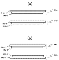
- (a) is a diagram showing the arrangement of the circuit pattern surface in the first and second embodiments
- (b) is a diagram showing the arrangement of the circuit pattern surface in the third embodiment.
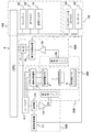
- FIG. 1 is a perspective view of an example of an open MRI apparatus according to the present invention
- FIG. 2 is a block diagram showing the overall configuration thereof.
- This open-type MRI apparatus uses a NMR phenomenon to obtain a tomographic image of a subject.
- a static magnetic field generation system 200 a gradient magnetic field generation system 300, a transmission system 500, and a reception system
- a system 600 a signal processing system 700, a sequencer 4, and a central processing unit (CPU) 8 are provided.
- CPU central processing unit
- the static magnetic field generation system 200 generates a static magnetic field that is uniform both spatially and temporally in the imaging space. Permanent magnet type, normal conduction type, or superconducting type static magnetic field generation sources are arranged around the imaging space. Made up.
- a pair of static magnetic field generating magnets are arranged to face each other with an imaging space interposed therebetween in order to generate a static magnetic field perpendicular to the body axis direction of the subject 1 placed in the imaging space.
- Up to four struts secure the imaging space and support the other static magnetic field generating magnet with respect to one static magnetic field generating magnet.
- a pair of (two) support columns (26-1, 26-2) that support the upper static magnetic field generating magnet from the lower static magnetic field generating magnet pass through the center of the imaging space.
- positioned on the horizontal line is shown.
- the angle formed by the straight line connecting the pair of columns and the straight line in the longitudinal direction of the bed 34 is not 90 degrees, but is less than 90 degrees or greater than 90 degrees.
- the gradient magnetic field generation system 300 drives a gradient magnetic field coil 9 that applies a gradient magnetic field in the three-axis directions of X, Y, and Z, which are the coordinate system (stationary coordinate system) of the open MRI apparatus, and the respective gradient magnetic field coils. It consists of a gradient magnetic field power supply 10, and by driving the gradient magnetic field power supply 10 of each coil according to a command from the sequencer 4 to be described later, gradient magnetic fields Gx, Gy, Gz are set in the three axis directions of X, Y, and Z. Apply.
- a slice direction gradient magnetic field pulse is applied in a direction orthogonal to the slice plane (imaging cross section) to set a slice plane for the subject 1, and the remaining two orthogonal to the slice plane and orthogonal to each other
- a phase encoding direction gradient magnetic field pulse (Gp) and a frequency encoding direction gradient magnetic field pulse (Gf) are applied in one direction, and position information in each direction is encoded into an echo signal.
- the sequencer 4 is a control means that repeatedly applies a high-frequency magnetic field pulse (hereinafter referred to as “RF pulse”) and a gradient magnetic field pulse in a predetermined pulse sequence, and operates under the control of the CPU 8 to collect tomographic image data of the subject 1.
- RF pulse high-frequency magnetic field pulse
- Various commands necessary for the transmission are sent to the transmission system 500, the gradient magnetic field generation system 300, and the reception system 600.
- the transmission system 500 irradiates the subject 1 with RF pulses in order to cause nuclear magnetic resonance to occur in the nuclear spins of the atoms constituting the living tissue of the subject 1, and includes a high-frequency oscillator 11, a modulator 12, and a high-frequency amplifier. 13 and a high-frequency coil (high-frequency transmission coil) 14 on the transmission side.
- the RF pulse output from the high-frequency oscillator 11 is amplitude-modulated by the modulator 12 at the timing according to the command from the sequencer 4, and the amplitude-modulated RF pulse is amplified by the high-frequency amplifier 13 and then placed close to the subject 1.
- the RF pulse is applied to the subject 1 by being supplied to the high-frequency transmission coil 14.
- the receiving system 600 detects an echo signal (NMR signal) emitted by nuclear magnetic resonance of nuclear spins constituting the biological tissue of the subject 1, and includes a receiving side high frequency coil (high frequency receiving coil) 26 and a signal amplifier. 15, a quadrature detector 16, and an A / D converter 17.
- the NMR signal of the response of the subject 1 induced by the electromagnetic wave irradiated from the high frequency transmitting coil 14 on the transmitting side was detected by the high frequency receiving coil 26 arranged close to the subject 1 and amplified by the signal amplifier 15 Thereafter, the signals are divided into two orthogonal signals by the quadrature phase detector 16 at a timing according to a command from the sequencer 4, converted into digital quantities by the A / D converter 17, and sent to the signal processing system 700.
- the signal processing system 700 performs various data processing and display and storage of processing results, and has an external storage device such as an optical disk 19 and a magnetic disk 18 and a display 20 made up of a CRT or the like.
- an external storage device such as an optical disk 19 and a magnetic disk 18 and a display 20 made up of a CRT or the like.
- the CPU 8 executes processing such as signal processing and image reconstruction, and displays the tomographic image of the subject 1 as a result on the display 20, and an external storage device On the magnetic disk 18 or the like.
- the operation unit 25 inputs various control information of the open MRI apparatus and control information of processing performed by the signal processing system 700, and includes a trackball or mouse 23 and a keyboard 24.
- the operation unit 25 is disposed in the vicinity of the display 20, and the operator interactively controls various processes of the open MRI apparatus through the operation unit 25 while looking at the display 20.
- the high-frequency transmission coil 14 and the gradient magnetic field coil 9 on the transmission side are opposed to the subject 1 in the static magnetic field space of the static magnetic field generation system 200 in which the subject 1 is inserted if the vertical magnetic field method is used. If the horizontal magnetic field method is used, it is installed so as to surround the subject 1.
- the high-frequency receiving coil 26 on the receiving side is disposed so as to face or surround the subject 1.
- the radionuclide to be imaged by an open MRI apparatus is a hydrogen nucleus (proton), which is a main constituent material of the subject, as widely used in clinical practice.
- proton a hydrogen nucleus
- the form or function of the human head, abdomen, limbs, etc. is imaged two-dimensionally or three-dimensionally.
- the open-type MRI apparatus of the present invention generates a static magnetic field (generally uniform both spatially and temporally) in the imaging space so as to face each other vertically with an imaging space in which the subject is placed therebetween.
- Each of the pair of high frequency transmission coil base plates has a shape different from that of at least one of the support structure supported by each of the pair of static magnetic field generating magnets.
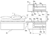
- FIG. 3 shows the configuration of the bed 34 and the half on the bed 34 side from the central axis of the static magnetic field generating magnet 2.
- the configuration of the half on the opposite side of the bed 34 from the central axis of the static magnetic field generating magnet 2 is substantially the same as the configuration of the half on the side of the bed 34 from the central axis of the static magnetic field generating magnet shown in FIG.
- symbol of each structure part which has a pair structure, "a" is attached to an upper part, and "b" is attached to a lower part, respectively.
- the open-type MRI apparatus shown in FIG. 3 has an upper part and a lower part that are vertically opposed to each other with an imaging space in between.
- the upper part includes a static magnetic field generating magnet 2a, a static magnetic field correction plate 30a, a gradient magnetic field coil 9a, a high frequency transmission coil 14a, a high frequency transmission coil base plate 31a, a base plate support member 32a, and an exterior cover 33a. It is configured.
- the lower part includes a static magnetic field generating magnet 2b, a static magnetic field correction plate 30b, a gradient magnetic field coil 9b, a high frequency transmission coil 14b, a high frequency transmission coil base plate 31b, a base plate support member 32b, It has an exterior cover 33b.
- the base plate 31a and the high-frequency transmission coil base plate 31b, and the exterior cover 33a and the exterior cover 33b each have a pair of configurations that face each other with an imaging space interposed therebetween.
- Arrangement order is the outer cover 33 (33a, 33b), the high frequency transmission coil 14 (14a, 14b) or the high frequency transmission coil base plate 31 (31a, 31b), and the gradient magnetic field coil 9 (9a, 9b) in order from the imaging space. ),
- the static magnetic field correction plate 30 (30a, 30b).
- a pair of static magnetic field generating magnets 2 (2a, 2b) are arranged opposite to each other with an imaging space in between
- a pair of static magnetic field correction plates 30 (30a, 30b) are disposed opposite to each other at a position on the imaging space side of the pair of static magnetic field generating magnets 2 (2a, 2b) with the imaging space interposed therebetween
- a pair of gradient magnetic field coils 9 (9a, 9b) are disposed opposite to each other at a position on the imaging space side of the pair of static magnetic field correction plates 30 (30a, 30b) with the imaging space interposed therebetween
- a pair of high-frequency transmission coil base plates 31 (31a, 31b) and a pair of high-frequency transmission coils 14 (14a, 14b) are formed of a pair of gradient magnetic field coils 9 (9a, 9b) with an imaging space therebetween. Oppositely arranged at a position on the imaging space side.
- the pair of exterior covers 33 (33a, 33b) are arranged to face the imaging space with the imaging space interposed therebetween, and make the surface on the imaging space side uniform and flat.
- Each static magnetic field generating magnet 2 (2a, 2b) is provided with a static magnetic field generating source composed of a superconducting coil inside a vacuum vessel having a gap at the center thereof.
- the gap is formed in the vacuum vessel as a concave portion with only one side open or a through hole with both sides open.
- the vacuum vessel has a cylindrical shape.
- recess are collectively referred to as a recess.
- a recess 35 (35a, 35b), which is a gap formed in the central part of the imaging space side of the vacuum vessel, has a cylindrical shape with an inner diameter D1, and in this recess 35, a static magnetic field correction plate 30 and a gradient magnetic field coil 9 A high-frequency transmission coil 14 is accommodated.
- the static magnetic field correction plate 30 has a substantially flat plate shape, holds correction iron for correcting the spatial uniformity of the static magnetic field, is fixed to the bottom surface in the recess 35, and is static magnetic field in the imaging space.
- the spatial nonuniformity is corrected to improve the uniformity.
- the gradient coil 9 has a substantially flat plate shape, is disposed in the concave portion 35 of the static magnetic field generating magnet 2, and is supported via a support member that penetrates the static magnetic field correction plate 30 from the bottom surface of the concave portion 35.
- the high-frequency transmission coil 14 has a substantially flat plate shape, and is disposed so as to be accommodated in the recess 35 while being fixed to the high-frequency transmission coil base plate 31.
- a circuit pattern (copper wire circuit and circuit component) for generating an RF pulse is formed on one surface of the flat plate-shaped high-frequency transmission coil.
- the high-frequency transmission coil base plate 31 is a support member for fixing the high-frequency transmission coil 14 and arranging the high-frequency transmission coil 14 in the recess 35.
- the feature of the open type MRI apparatus according to the present invention is that the high-frequency transmission coil base plate 31 is formed in an up and down asymmetric shape and support structure using the concave portion 35, so that the subject can be opened without impairing openness. The uniformity of the static magnetic field can be ensured even in the state of being arranged in the imaging space.
- the asymmetric shape and support structure of the base plate 31 for the high-frequency transmission coil will be described in detail in each embodiment of the present invention described later.
- the base plate support member 32 is a support member for supporting the high frequency transmission coil base plate 31 from the static magnetic field generating magnet 2.
- the support structure will be described in detail in each embodiment of the present invention described later.
- the exterior cover 33 covers the surface on the imaging space side of the high-frequency transmission coil 14 and the base plate 31 for the high-frequency transmission coil and the static magnetic field generating magnet 2, faces the imaging space, and the surface on the imaging space side is uniform and It is what makes it flat. Thereby, traveling of the top board is improved.
- the high frequency transmission coil base plates 31a and 31b and the exterior covers 33a and 33b are preferably high in density, non-magnetic and non-conductive.
- materials such as glass fiber reinforced plastic and engineer plastic are used.
- the base plate support members 32a and 32b are preferably non-magnetic and high in strength, and metals such as stainless steel and brass are used.
- the high frequency transmission coil base plates 31a and 31b and the outer covers 33a and 33b may have a structure divided into two or more in consideration of assembling.
- Example 1 of the present invention will be described.
- the thickness and shape of the base plate for the high-frequency transmission coil and the support structure thereof are made different from each other in the upper and lower directions, so that the upper and lower sides are asymmetric.
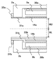
- the first embodiment will be described in detail with reference to FIG.
- the high frequency transmission coil base plate 31a is accommodated in the recess 35a of the static magnetic field generating magnet 2a and supported from the static magnetic field generating magnet 2a via the base plate support member 32a.
- the base plate support member 32a is fixed to the upper surface of the static magnetic field generating magnet 2a and opposite to the imaging space, and passes through the concave portion of the static magnetic field generating magnet 2a to support the high frequency transmission coil base plate 31a.
- the base plate support member 32a is fixed to the static magnetic field generating magnet 2a by screws or welding. Further, a gap is provided between the side surface of the concave portion 35a of the static magnetic field generating magnet 2a and the base plate support member 32a so as not to contact each other. This prevents vibration from being transmitted from the side surface of the recess 35a of the static magnetic field generating magnet 2a to the base plate support member 32a.
- the base plate 31b for the high-frequency transmission coil is supported from the static magnetic field generating magnet 2b via a base plate support member 32b fixed to the outer side surface of the static magnetic field generating magnet 2b.
- the base plate 31b for the high-frequency transmission coil comes into contact with the surface on the imaging space side of the static magnetic field generating magnet 2b and is also supported from the surface.
- the base plate support member 32b is fixed to the static magnetic field generating magnet 2b by screws or welding.
- the subject 1 is mounted on the top plate 37 that travels on the upper surface of the bed 34 and the upper surface of the exterior cover 33b, and is arranged in the imaging space.
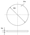
- FIG. 4 shows the base plate 31a for the high-frequency transmission coil.
- the outer diameter DU of the high-frequency transmission coil base plate 31a is smaller than the inner diameter D1 of the recess 35a of the magnetic field generator 2, and larger than the outer diameter of the high-frequency transmission coil 14a.
- the high-frequency transmission coil 14a can be fixed to the high-frequency transmission coil base plate 31a and disposed inside the recess 35a of the static magnetic field generating magnet 2a.
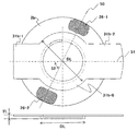
- FIG. 5 shows the base plate 31b for the high-frequency transmission coil.
- the base plate 31b for the high-frequency transmission coil is provided between the outer cover 33b serving as the traveling surface of the top plate 37 and the static magnetic field generating magnet 2b, and has an outer diameter DL larger than the inner diameter D1 of the recess 35b of the static magnetic field generating magnet 2b.
- the central portion 31b-0 and the both sides of the central portion 31b-0 extend beyond the outer side surface of the static magnetic field generating magnet 2b across the cylindrical vacuum vessel of the lower static magnetic field generating magnet 2b. It has extension parts 31b-1 and 31b-2.
- the central portion 31b-0 is provided with a concave portion that is concentric with the outer diameter DL and larger than the outer shape of the high-frequency transmission coil 14 on the surface on the imaging space side, and accommodates and fixes the high-frequency transmission coil 14b in the concave portion.
- each extending part 31b-1, 31b-2 extends beyond the outer side surface of the static magnetic field generating magnet 2b across the cylindrical vacuum vessel of the static magnetic field generating magnet 2b from the central part 31b-0. It has a rectangular shape and supports the top plate 37 via the exterior cover 33b. In order to increase the travelable distance of the top plate 37, the lengths of the extending portions 31b-1 and 31b-2 in the longitudinal direction (that is, the travel direction of the top plate 37) are different from each other.
- the extension part 31b-2 on the opposite side of the bed 34 is made longer than the extension part 31b-1 on the bed 34 side.
- the extension part 31b-1 is an end part thereof, and the extension part 31b-2 is a middle part thereof.
- the extension part 31b-1 is fixed to the base plate support member 32b, and the static magnetic field generating magnet 2b is fixed via the base plate support member 32b. It is supported from the outer side surface.
- high-frequency transmission is performed such that an angle 52 formed by a straight line 50 connecting the pair of support posts 26-1, 26-2 and a straight line 51 in the longitudinal direction of the base plate 31b for the high-frequency transmission coil is less than 90 degrees or greater than 90 degrees.
- the coil base plate 31b is fixed to the static magnetic field generating magnet 2b. That is, the top 37 on which the subject 1 is placed is inserted into the imaging space from an oblique direction with respect to the straight line 50 connecting the pair of support posts 26-1, 26-2, thereby improving the sense of openness felt by the subject. .
- the plate thickness of each of the pair of high frequency transmitting coil base plates 31 (31a, 31b) is different and has an asymmetric shape.
- the plate thickness TL of the lower high-frequency transmission coil base plate 31b (that is, the side receiving the weight of the subject 1) is thicker than the plate thickness TU of the upper high-frequency transmission coil base plate 31a. Yes.
- each circuit pattern surface of the high-frequency transmission coil 14 fixed to the base plate 31 for the asymmetrical high-frequency transmission coil in this way (that is, the surface on which the copper wire serving as the coil electrical circuit is disposed) and imaging The distance from the center of the space needs to be substantially the same at the top and bottom.
- the high-frequency transmission coil 14b on the lower side is such that its circuit pattern surface 14b-2 is on the opposite side of the imaging space in the coil base 14b-1 (that is, the high-frequency transmission coil 14b Is fixed to the base plate 31b for the high frequency transmission coil.
- the high-frequency transmission coil 14a is fixed to the high-frequency transmission coil base plate 31a so that the circuit pattern surface 14a-2 is on the imaging space side of the coil base 14a-1.
- the upper side can be made longer than the lower side with respect to the distance from the center of the imaging space to the exterior cover 33.
- the distance HU between the exterior cover 33a and the center of the imaging space is set to the distance between the exterior cover 33b and the center of the imaging space.
- the distance HL can be longer than the distance HL, and the space in the upper part from the center of the imaging space can be made wider than the space in the lower part. As a result, the feeling of opening felt by the subject can be improved.
- the load on the top plate 34 and the subject 1 is applied to the exterior cover 33b and the base plate 31b for the high frequency transmission coil. Supported. Since the base plate support member 32b of the base plate 31b for the high frequency transmission coil and the support point of the static magnetic field correction plate 30b fixed in the recess of the static magnetic field generating magnet 2b are sufficiently separated from each other, The displacement received by the static magnetic field correction plate 30b due to the load of the subject 1 is reduced, and the spatial uniformity of the static magnetic field can be ensured.
- the base plate for the high-frequency transmission coil is 1) For the plate thickness, make the lower side thicker than the upper side. 2) About the shape, a concave portion is provided on the lower side, and the high-frequency transmission coil is accommodated and fixed in the concave portion. 3) As for the support structure, the upper side is supported from the surface opposite to the imaging space of the static magnetic field generating magnet, and the lower side is supported from the outer side surface of the static magnetic field generating magnet.
- a base plate for a high-frequency transmission coil having a structure in which at least one of the above 1) to 3) is combined may be used.
- the thickness and shape of the base plate for the high-frequency transmission coil and the support structure thereof asymmetric, it is possible to maintain the spatial uniformity of the static magnetic field while ensuring the openness.
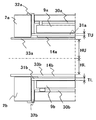
- the high-frequency transmission coil base plate 31a also serves as the exterior cover 33a and is supported from the outer side surface of the static magnetic field generating magnet 2a in the upper portion.
- the difference from the first embodiment is the shape and support structure of the base plate 31a for the high-frequency transmission coil and the base plate support member 32a.
- the lower part is the same as in the first embodiment.
- the base plate 31a for the high-frequency transmission coil is larger than the recessed portion inner diameter D1 of the static magnetic field generating magnet 2a and covers the surface of the static magnetic field generating magnet 2a on the imaging space side, thereby also serving as the exterior cover 33a. That is, the exterior cover 33a is not required by forming the surface on the imaging space side of the base plate 31a for the high-frequency transmission coil uniformly and flatly.
- the high frequency transmission coil base plate 31a is supported by a base plate support member 32a on the outer side surface of the static magnetic field generating magnet 2a, with the high frequency transmission coil 14a fixed to the upper surface (the surface opposite to the imaging space).
- the base plate support member 32a is fixed to the static magnetic field generating magnet 2a by screws or welding.
- the high-frequency transmission coil 14b on the lower side has a circuit pattern surface 14b-2 at the coil base portion 14b-1.
- the high frequency transmission coil base plate 31b is fixed so as to be opposite to the imaging space.
- the high-frequency transmission coil 14a is fixed to the high-frequency transmission coil base plate 31a so that the circuit pattern surface 14a-2 is on the imaging space side of the coil base 14a-1.
- the relative positional relationship between the static magnetic field generating magnet 2a and the static magnetic field correction plate 30a is maintained, Uniformity can be ensured.
- the high frequency transmission coil base plate 31a also serves as the exterior cover 33a, the exterior cover 33a can be omitted.
- the distance HU between the high frequency transmission coil base plate 31a and the center of the imaging space is made longer than the distance HL between the exterior cover 33b and the center of the imaging space. Can do.
- Example 3 of the present invention will be described.
- the high-frequency transmission coil base plate 31b is housed in the recess 35b of the static magnetic field generating magnet 2b and supported from the lower surface of the static magnetic field generating magnet 2b.
- the difference from the first embodiment is a high-frequency transmission coil base plate 31b and a base plate support member 32b.
- the upper part is the same as in the first embodiment.
- only different portions will be described with reference to FIG. 7, and description of the same portions will be omitted.
- the base plate 31b for the high-frequency transmission coil is smaller than the inner diameter D1 of the concave portion 35b of the static magnetic field generating magnet 2b, and is accommodated in the concave portion 35b, and the static magnetic field generating magnet 2b is interposed via the base plate support member 32b. Supported by.
- the base plate support member 32b is fixed to the lower surface of the static magnetic field generating magnet 2b (that is, the surface on the opposite side of the imaging space), passes through the recess 35b of the static magnetic field generating magnet 2b, and is used for the base plate 31b for the high frequency transmission coil Support.
- the base plate support member 32b is fixed to the static magnetic field generating magnet 2b by screws or welding.
- a gap is provided between the side surface of the recess 35b of the static magnetic field generating magnet 2b and the base plate support member 32b so as not to contact each other. This prevents vibration from being transmitted from the side surface of the recess 35b of the static magnetic field generating magnet 2b to the base plate support member 32b.
- the exterior cover 33b is directly supported from the surface on the imaging space side of the static magnetic field generating magnet 2b. As a result, the distance HL from the outer cover 33b and the center of the imaging space can be increased, and the space from the center of the imaging space to the lower part can be made wider than in the first embodiment, and the subject feels An open feeling can be improved.
- the plate thickness TL of the high-frequency transmission coil base plate 31b is thicker than the plate thickness TU of the high-frequency transmission coil base plate 31a, To do.
- the gap between the gradient magnetic field coil 9b and the high-frequency transmission coil base plate 31b on the lower side is narrowed, so that the vibration isolating material and the sound absorbing material arranged in the narrowed gap are reduced, or the gap ( It may be left in the non-contact state with the gradient coil 3b.
- the circuit pattern surfaces 14a-2 and 14b-2 are located on the upper and lower sides of the imaging bases 14a-1 and 14b-1, respectively. Even if the upper and lower high-frequency transmission coils 14a and 14b are arranged on the high-frequency transmission coil base plate 31 so as to be on the side, the distance from the center of the imaging space to each circuit pattern surface 14a-2 and 14b-2 is substantially reduced. Be the same.
- Example 3 As described above, according to the configuration of Example 3, as in Example 1 described above, the relative positional relationship between the static magnetic field generating magnet 2 and the static magnetic field correction plates 30a and 30b is maintained, and the static magnetic field Uniformity can be ensured. Furthermore, since the base plate 31b for the high-frequency transmission coil is housed in the recess 35b of the static magnetic field generating magnet 2b, the distance HL from the center of the imaging space to the base plate 31b for the high-frequency transmission coil can be further increased. The space from the center of the space to the lower portion can be made wider than in the first embodiment.
- 1 subject 200 static magnetic field generation system, 300 gradient magnetic field generation system, 4 sequencer, 500 transmission system, 600 reception system, 700 signal processing system, 8 central processing unit (CPU), 9 gradient magnetic field coils (9a, 9b), 10 Gradient magnetic field power supply, 11 High frequency transmitter, 12 Modulator, 13 High frequency amplifier, 14, 14a, 14b High frequency coil (high frequency transmission coil), 15 Signal amplifier, 16 Quadrature phase detector, 17 A / D converter, 18 Magnetic Disc, 19 optical disc, 20 display, 21 ROM, 22 RAM, 23 trackball or mouse, 24 keyboard, 25 operation unit, 26 high frequency coil (high frequency receiving coil), 30, 30a, 30b static magnetic field correction plate, 31, 31a, 31b Base plate for high frequency transmission coil, 32, 32a, 32b Base plate support member, 33, 33a, 33b Exterior cover, 34 bed
Landscapes
- Health & Medical Sciences (AREA)
- Life Sciences & Earth Sciences (AREA)
- Physics & Mathematics (AREA)
- Medical Informatics (AREA)
- Surgery (AREA)
- Engineering & Computer Science (AREA)
- Biomedical Technology (AREA)
- Heart & Thoracic Surgery (AREA)
- Biophysics (AREA)
- Molecular Biology (AREA)
- Pathology (AREA)
- Animal Behavior & Ethology (AREA)
- General Health & Medical Sciences (AREA)
- Public Health (AREA)
- Veterinary Medicine (AREA)
- Nuclear Medicine, Radiotherapy & Molecular Imaging (AREA)
- High Energy & Nuclear Physics (AREA)
- Radiology & Medical Imaging (AREA)
- Magnetic Resonance Imaging Apparatus (AREA)
Abstract
L'objet de la présente invention est de fournir un appareil d'IRM ouvert qui permette, sans compromettre l'ouverture, de maintenir l'homogénéité d'un champ magnétique statique dans un espace d'imagerie, même lorsqu'un objet est placé dans l'espace d'imagerie. L'appareil d'IRM ouvert comprend : une paire d'aimants générant un champ magnétique statique qui se font face l'un l'autre, sont positionnés au-dessus et au-dessous d'un espace d'imagerie dans lequel un objet est placé et génèrent un champ magnétique statique dans l'espace d'imagerie ; une paire de bobines de champ magnétique à gradient qui se font face l'une l'autre sont positionnées au-dessus et au-dessous de l'espace d'imagerie et sont disposées plus près de l'espace d'imagerie que la paire d'aimants générant un champ magnétique statique ; une paire de bobines d'émission de radiofréquence qui se font face l'une l'autre sont positionnées au-dessus et au-dessous de l'espace d'imagerie et sont disposées plus près de l'espace d'imagerie que la paire de bobines de champ magnétique à gradient et une paire de plaques de base pour les bobines d'émission de radiofréquence qui supportent les bobines d'émission de radiofréquence respectives de la paire par rapport aux aimants générant un champ magnétique statique. La paire de plaques de base pour les bobines d'émission de radiofréquence ont des formes mutuellement différentes et/ou des structures de support mutuellement différentes supportées par la paire d'aimants générant un champ magnétique statique.
Applications Claiming Priority (2)
| Application Number | Priority Date | Filing Date | Title |
|---|---|---|---|
| JP2015-118126 | 2015-06-11 | ||
| JP2015118126 | 2015-06-11 |
Publications (1)
| Publication Number | Publication Date |
|---|---|
| WO2016199640A1 true WO2016199640A1 (fr) | 2016-12-15 |
Family
ID=57503902
Family Applications (1)
| Application Number | Title | Priority Date | Filing Date |
|---|---|---|---|
| PCT/JP2016/066205 Ceased WO2016199640A1 (fr) | 2015-06-11 | 2016-06-01 | Appareil d'imagerie par résonance magnétique ouvert |
Country Status (1)
| Country | Link |
|---|---|
| WO (1) | WO2016199640A1 (fr) |
Cited By (1)
| Publication number | Priority date | Publication date | Assignee | Title |
|---|---|---|---|---|
| WO2020195983A1 (fr) * | 2019-03-22 | 2020-10-01 | 日本電産リード株式会社 | Dispositif d'inspection |
Citations (6)
| Publication number | Priority date | Publication date | Assignee | Title |
|---|---|---|---|---|
| JP2000333929A (ja) * | 1999-05-25 | 2000-12-05 | Hitachi Medical Corp | Mri装置用静磁場発生装置およびそれを用いたmri装置 |
| JP2001299719A (ja) * | 2000-04-27 | 2001-10-30 | Hitachi Medical Corp | 磁気共鳴イメージング装置 |
| JP2004173722A (ja) * | 2002-11-25 | 2004-06-24 | Hitachi Ltd | 磁気共鳴イメージング装置 |
| JP2005304597A (ja) * | 2004-04-19 | 2005-11-04 | Hitachi Medical Corp | 磁気共鳴イメージング装置 |
| JP2006136531A (ja) * | 2004-11-12 | 2006-06-01 | Mitsubishi Electric Corp | 磁気共鳴イメージング装置 |
| JP2008212504A (ja) * | 2007-03-07 | 2008-09-18 | Hitachi Medical Corp | 磁気共鳴イメージング装置 |
-
2016
- 2016-06-01 WO PCT/JP2016/066205 patent/WO2016199640A1/fr not_active Ceased
Patent Citations (6)
| Publication number | Priority date | Publication date | Assignee | Title |
|---|---|---|---|---|
| JP2000333929A (ja) * | 1999-05-25 | 2000-12-05 | Hitachi Medical Corp | Mri装置用静磁場発生装置およびそれを用いたmri装置 |
| JP2001299719A (ja) * | 2000-04-27 | 2001-10-30 | Hitachi Medical Corp | 磁気共鳴イメージング装置 |
| JP2004173722A (ja) * | 2002-11-25 | 2004-06-24 | Hitachi Ltd | 磁気共鳴イメージング装置 |
| JP2005304597A (ja) * | 2004-04-19 | 2005-11-04 | Hitachi Medical Corp | 磁気共鳴イメージング装置 |
| JP2006136531A (ja) * | 2004-11-12 | 2006-06-01 | Mitsubishi Electric Corp | 磁気共鳴イメージング装置 |
| JP2008212504A (ja) * | 2007-03-07 | 2008-09-18 | Hitachi Medical Corp | 磁気共鳴イメージング装置 |
Cited By (1)
| Publication number | Priority date | Publication date | Assignee | Title |
|---|---|---|---|---|
| WO2020195983A1 (fr) * | 2019-03-22 | 2020-10-01 | 日本電産リード株式会社 | Dispositif d'inspection |
Similar Documents
| Publication | Publication Date | Title |
|---|---|---|
| US7034537B2 (en) | MRI apparatus correcting vibratory static magnetic field fluctuations, by utilizing the static magnetic fluctuation itself | |
| US10890637B2 (en) | Magnetic resonance gradient coil for generating a magnetic field gradient and a magnetic field of a higher order | |
| JP5243437B2 (ja) | オープン型mri装置及びオープン型超電導mri装置 | |
| WO2015133352A1 (fr) | Système d'imagerie par résonance magnétique, système de réglage d'uniformité de champ magnétique statique, procédé de réglage d'uniformité de champ magnétique, et programme de réglage d'uniformité de champ magnétique | |
| JP5566085B2 (ja) | 磁気共鳴イメージング装置用傾斜磁場コイル、これを用いた磁気共鳴イメージング装置 | |
| US7123014B2 (en) | Magnetic gradient field projection | |
| JP5771354B2 (ja) | 磁気共鳴イメージング装置用受信コイル装置、およびそれを用いた磁気共鳴イメージング装置 | |
| WO2016199640A1 (fr) | Appareil d'imagerie par résonance magnétique ouvert | |
| JP2006518242A (ja) | Mriシステムの振動による磁界の乱れの補償 | |
| JP5670037B2 (ja) | 静磁場測定器 | |
| JP2015039461A (ja) | 磁気共鳴イメージング装置 | |
| JP6334444B2 (ja) | 磁気共鳴イメージング装置 | |
| JP4416578B2 (ja) | 磁気共鳴イメージング装置 | |
| JP2005160842A (ja) | 磁気共鳴イメージング装置 | |
| JPH10262947A (ja) | 磁気共鳴検査装置 | |
| JP2003116812A5 (fr) | ||
| JP4817966B2 (ja) | Mri装置およびmri装置用の高周波コイル | |
| JP5149004B2 (ja) | 磁気共鳴イメージング装置 | |
| JP5322614B2 (ja) | 磁気共鳴イメージング装置 | |
| JP4969933B2 (ja) | 磁気共鳴イメージング装置 | |
| JP2011015702A (ja) | 磁気共鳴イメージング装置 | |
| Rim | Synthesized Magnetic Field Focusing Using a Current-Controlled Coil Array | |
| JP6151583B2 (ja) | 静磁場発生磁石及び磁気共鳴撮影装置 | |
| JP2013244288A (ja) | 磁気共鳴イメージング装置及びその傾斜磁場コイル装置 | |
| JP2017086736A (ja) | 磁気共鳴イメージング装置、及び方法 |
Legal Events
| Date | Code | Title | Description |
|---|---|---|---|
| 121 | Ep: the epo has been informed by wipo that ep was designated in this application |
Ref document number: 16807347 Country of ref document: EP Kind code of ref document: A1 |
|
| NENP | Non-entry into the national phase |
Ref country code: DE |
|
| 122 | Ep: pct application non-entry in european phase |
Ref document number: 16807347 Country of ref document: EP Kind code of ref document: A1 |
|
| NENP | Non-entry into the national phase |
Ref country code: JP |