WO2016199654A1 - 作業機械の油圧駆動システム - Google Patents
作業機械の油圧駆動システム Download PDFInfo
- Publication number
- WO2016199654A1 WO2016199654A1 PCT/JP2016/066307 JP2016066307W WO2016199654A1 WO 2016199654 A1 WO2016199654 A1 WO 2016199654A1 JP 2016066307 W JP2016066307 W JP 2016066307W WO 2016199654 A1 WO2016199654 A1 WO 2016199654A1
- Authority
- WO
- WIPO (PCT)
- Prior art keywords
- pressure
- regeneration
- hydraulic
- hydraulic actuator
- flow rate
- Prior art date
- Legal status (The legal status is an assumption and is not a legal conclusion. Google has not performed a legal analysis and makes no representation as to the accuracy of the status listed.)
- Ceased
Links
Images





Classifications
-
- E—FIXED CONSTRUCTIONS
- E02—HYDRAULIC ENGINEERING; FOUNDATIONS; SOIL SHIFTING
- E02F—DREDGING; SOIL-SHIFTING
- E02F9/00—Component parts of dredgers or soil-shifting machines, not restricted to one of the kinds covered by groups E02F3/00 - E02F7/00
- E02F9/20—Drives; Control devices
- E02F9/22—Hydraulic or pneumatic drives
- E02F9/2221—Control of flow rate; Load sensing arrangements
-
- E—FIXED CONSTRUCTIONS
- E02—HYDRAULIC ENGINEERING; FOUNDATIONS; SOIL SHIFTING
- E02F—DREDGING; SOIL-SHIFTING
- E02F9/00—Component parts of dredgers or soil-shifting machines, not restricted to one of the kinds covered by groups E02F3/00 - E02F7/00
- E02F9/20—Drives; Control devices
- E02F9/22—Hydraulic or pneumatic drives
- E02F9/2203—Arrangements for controlling the attitude of actuators, e.g. speed, floating function
-
- F—MECHANICAL ENGINEERING; LIGHTING; HEATING; WEAPONS; BLASTING
- F15—FLUID-PRESSURE ACTUATORS; HYDRAULICS OR PNEUMATICS IN GENERAL
- F15B—SYSTEMS ACTING BY MEANS OF FLUIDS IN GENERAL; FLUID-PRESSURE ACTUATORS, e.g. SERVOMOTORS; DETAILS OF FLUID-PRESSURE SYSTEMS, NOT OTHERWISE PROVIDED FOR
- F15B21/00—Common features of fluid actuator systems; Fluid-pressure actuator systems or details thereof, not covered by any other group of this subclass
- F15B21/14—Energy-recuperation means
-
- E—FIXED CONSTRUCTIONS
- E02—HYDRAULIC ENGINEERING; FOUNDATIONS; SOIL SHIFTING
- E02F—DREDGING; SOIL-SHIFTING
- E02F9/00—Component parts of dredgers or soil-shifting machines, not restricted to one of the kinds covered by groups E02F3/00 - E02F7/00
- E02F9/20—Drives; Control devices
- E02F9/22—Hydraulic or pneumatic drives
- E02F9/2217—Hydraulic or pneumatic drives with energy recovery arrangements, e.g. using accumulators, flywheels
-
- E—FIXED CONSTRUCTIONS
- E02—HYDRAULIC ENGINEERING; FOUNDATIONS; SOIL SHIFTING
- E02F—DREDGING; SOIL-SHIFTING
- E02F9/00—Component parts of dredgers or soil-shifting machines, not restricted to one of the kinds covered by groups E02F3/00 - E02F7/00
- E02F9/20—Drives; Control devices
- E02F9/22—Hydraulic or pneumatic drives
- E02F9/2264—Arrangements or adaptations of elements for hydraulic drives
- E02F9/2267—Valves or distributors
-
- E—FIXED CONSTRUCTIONS
- E02—HYDRAULIC ENGINEERING; FOUNDATIONS; SOIL SHIFTING
- E02F—DREDGING; SOIL-SHIFTING
- E02F9/00—Component parts of dredgers or soil-shifting machines, not restricted to one of the kinds covered by groups E02F3/00 - E02F7/00
- E02F9/20—Drives; Control devices
- E02F9/22—Hydraulic or pneumatic drives
- E02F9/2264—Arrangements or adaptations of elements for hydraulic drives
- E02F9/2271—Actuators and supports therefor and protection therefor
-
- E—FIXED CONSTRUCTIONS
- E02—HYDRAULIC ENGINEERING; FOUNDATIONS; SOIL SHIFTING
- E02F—DREDGING; SOIL-SHIFTING
- E02F9/00—Component parts of dredgers or soil-shifting machines, not restricted to one of the kinds covered by groups E02F3/00 - E02F7/00
- E02F9/20—Drives; Control devices
- E02F9/22—Hydraulic or pneumatic drives
- E02F9/2278—Hydraulic circuits
- E02F9/2285—Pilot-operated systems
-
- E—FIXED CONSTRUCTIONS
- E02—HYDRAULIC ENGINEERING; FOUNDATIONS; SOIL SHIFTING
- E02F—DREDGING; SOIL-SHIFTING
- E02F9/00—Component parts of dredgers or soil-shifting machines, not restricted to one of the kinds covered by groups E02F3/00 - E02F7/00
- E02F9/20—Drives; Control devices
- E02F9/22—Hydraulic or pneumatic drives
- E02F9/2278—Hydraulic circuits
- E02F9/2292—Systems with two or more pumps
-
- E—FIXED CONSTRUCTIONS
- E02—HYDRAULIC ENGINEERING; FOUNDATIONS; SOIL SHIFTING
- E02F—DREDGING; SOIL-SHIFTING
- E02F9/00—Component parts of dredgers or soil-shifting machines, not restricted to one of the kinds covered by groups E02F3/00 - E02F7/00
- E02F9/20—Drives; Control devices
- E02F9/22—Hydraulic or pneumatic drives
- E02F9/2278—Hydraulic circuits
- E02F9/2296—Systems with a variable displacement pump
-
- E—FIXED CONSTRUCTIONS
- E02—HYDRAULIC ENGINEERING; FOUNDATIONS; SOIL SHIFTING
- E02F—DREDGING; SOIL-SHIFTING
- E02F9/00—Component parts of dredgers or soil-shifting machines, not restricted to one of the kinds covered by groups E02F3/00 - E02F7/00
- E02F9/26—Indicating devices
- E02F9/267—Diagnosing or detecting failure of vehicles
- E02F9/268—Diagnosing or detecting failure of vehicles with failure correction follow-up actions
-
- F—MECHANICAL ENGINEERING; LIGHTING; HEATING; WEAPONS; BLASTING
- F15—FLUID-PRESSURE ACTUATORS; HYDRAULICS OR PNEUMATICS IN GENERAL
- F15B—SYSTEMS ACTING BY MEANS OF FLUIDS IN GENERAL; FLUID-PRESSURE ACTUATORS, e.g. SERVOMOTORS; DETAILS OF FLUID-PRESSURE SYSTEMS, NOT OTHERWISE PROVIDED FOR
- F15B19/00—Testing; Calibrating; Fault detection or monitoring; Simulation or modelling of fluid-pressure systems or apparatus not otherwise provided for
- F15B19/005—Fault detection or monitoring
-
- F—MECHANICAL ENGINEERING; LIGHTING; HEATING; WEAPONS; BLASTING
- F15—FLUID-PRESSURE ACTUATORS; HYDRAULICS OR PNEUMATICS IN GENERAL
- F15B—SYSTEMS ACTING BY MEANS OF FLUIDS IN GENERAL; FLUID-PRESSURE ACTUATORS, e.g. SERVOMOTORS; DETAILS OF FLUID-PRESSURE SYSTEMS, NOT OTHERWISE PROVIDED FOR
- F15B20/00—Safety arrangements for fluid actuator systems; Applications of safety devices in fluid actuator systems; Emergency measures for fluid actuator systems
-
- F—MECHANICAL ENGINEERING; LIGHTING; HEATING; WEAPONS; BLASTING
- F15—FLUID-PRESSURE ACTUATORS; HYDRAULICS OR PNEUMATICS IN GENERAL
- F15B—SYSTEMS ACTING BY MEANS OF FLUIDS IN GENERAL; FLUID-PRESSURE ACTUATORS, e.g. SERVOMOTORS; DETAILS OF FLUID-PRESSURE SYSTEMS, NOT OTHERWISE PROVIDED FOR
- F15B20/00—Safety arrangements for fluid actuator systems; Applications of safety devices in fluid actuator systems; Emergency measures for fluid actuator systems
- F15B20/004—Fluid pressure supply failure
-
- F—MECHANICAL ENGINEERING; LIGHTING; HEATING; WEAPONS; BLASTING
- F15—FLUID-PRESSURE ACTUATORS; HYDRAULICS OR PNEUMATICS IN GENERAL
- F15B—SYSTEMS ACTING BY MEANS OF FLUIDS IN GENERAL; FLUID-PRESSURE ACTUATORS, e.g. SERVOMOTORS; DETAILS OF FLUID-PRESSURE SYSTEMS, NOT OTHERWISE PROVIDED FOR
- F15B20/00—Safety arrangements for fluid actuator systems; Applications of safety devices in fluid actuator systems; Emergency measures for fluid actuator systems
- F15B20/002—Electrical failure
-
- F—MECHANICAL ENGINEERING; LIGHTING; HEATING; WEAPONS; BLASTING
- F15—FLUID-PRESSURE ACTUATORS; HYDRAULICS OR PNEUMATICS IN GENERAL
- F15B—SYSTEMS ACTING BY MEANS OF FLUIDS IN GENERAL; FLUID-PRESSURE ACTUATORS, e.g. SERVOMOTORS; DETAILS OF FLUID-PRESSURE SYSTEMS, NOT OTHERWISE PROVIDED FOR
- F15B20/00—Safety arrangements for fluid actuator systems; Applications of safety devices in fluid actuator systems; Emergency measures for fluid actuator systems
- F15B20/007—Overload
-
- F—MECHANICAL ENGINEERING; LIGHTING; HEATING; WEAPONS; BLASTING
- F15—FLUID-PRESSURE ACTUATORS; HYDRAULICS OR PNEUMATICS IN GENERAL
- F15B—SYSTEMS ACTING BY MEANS OF FLUIDS IN GENERAL; FLUID-PRESSURE ACTUATORS, e.g. SERVOMOTORS; DETAILS OF FLUID-PRESSURE SYSTEMS, NOT OTHERWISE PROVIDED FOR
- F15B2211/00—Circuits for servomotor systems
- F15B2211/20—Fluid pressure source, e.g. accumulator or variable axial piston pump
- F15B2211/205—Systems with pumps
- F15B2211/2053—Type of pump
- F15B2211/20546—Type of pump variable capacity
-
- F—MECHANICAL ENGINEERING; LIGHTING; HEATING; WEAPONS; BLASTING
- F15—FLUID-PRESSURE ACTUATORS; HYDRAULICS OR PNEUMATICS IN GENERAL
- F15B—SYSTEMS ACTING BY MEANS OF FLUIDS IN GENERAL; FLUID-PRESSURE ACTUATORS, e.g. SERVOMOTORS; DETAILS OF FLUID-PRESSURE SYSTEMS, NOT OTHERWISE PROVIDED FOR
- F15B2211/00—Circuits for servomotor systems
- F15B2211/20—Fluid pressure source, e.g. accumulator or variable axial piston pump
- F15B2211/205—Systems with pumps
- F15B2211/20576—Systems with pumps with multiple pumps
-
- F—MECHANICAL ENGINEERING; LIGHTING; HEATING; WEAPONS; BLASTING
- F15—FLUID-PRESSURE ACTUATORS; HYDRAULICS OR PNEUMATICS IN GENERAL
- F15B—SYSTEMS ACTING BY MEANS OF FLUIDS IN GENERAL; FLUID-PRESSURE ACTUATORS, e.g. SERVOMOTORS; DETAILS OF FLUID-PRESSURE SYSTEMS, NOT OTHERWISE PROVIDED FOR
- F15B2211/00—Circuits for servomotor systems
- F15B2211/30—Directional control
- F15B2211/305—Directional control characterised by the type of valves
- F15B2211/3056—Assemblies of multiple valves
- F15B2211/30565—Assemblies of multiple valves having multiple valves for a single output member, e.g. for creating higher valve function by use of multiple valves like two 2/2-valves replacing a 5/3-valve
- F15B2211/3058—Assemblies of multiple valves having multiple valves for a single output member, e.g. for creating higher valve function by use of multiple valves like two 2/2-valves replacing a 5/3-valve having additional valves for interconnecting the fluid chambers of a double-acting actuator, e.g. for regeneration mode or for floating mode
-
- F—MECHANICAL ENGINEERING; LIGHTING; HEATING; WEAPONS; BLASTING
- F15—FLUID-PRESSURE ACTUATORS; HYDRAULICS OR PNEUMATICS IN GENERAL
- F15B—SYSTEMS ACTING BY MEANS OF FLUIDS IN GENERAL; FLUID-PRESSURE ACTUATORS, e.g. SERVOMOTORS; DETAILS OF FLUID-PRESSURE SYSTEMS, NOT OTHERWISE PROVIDED FOR
- F15B2211/00—Circuits for servomotor systems
- F15B2211/30—Directional control
- F15B2211/305—Directional control characterised by the type of valves
- F15B2211/3056—Assemblies of multiple valves
- F15B2211/3059—Assemblies of multiple valves having multiple valves for multiple output members
- F15B2211/30595—Assemblies of multiple valves having multiple valves for multiple output members with additional valves between the groups of valves for multiple output members
-
- F—MECHANICAL ENGINEERING; LIGHTING; HEATING; WEAPONS; BLASTING
- F15—FLUID-PRESSURE ACTUATORS; HYDRAULICS OR PNEUMATICS IN GENERAL
- F15B—SYSTEMS ACTING BY MEANS OF FLUIDS IN GENERAL; FLUID-PRESSURE ACTUATORS, e.g. SERVOMOTORS; DETAILS OF FLUID-PRESSURE SYSTEMS, NOT OTHERWISE PROVIDED FOR
- F15B2211/00—Circuits for servomotor systems
- F15B2211/60—Circuit components or control therefor
- F15B2211/63—Electronic controllers
- F15B2211/6303—Electronic controllers using input signals
- F15B2211/6306—Electronic controllers using input signals representing a pressure
- F15B2211/6309—Electronic controllers using input signals representing a pressure the pressure being a pressure source supply pressure
-
- F—MECHANICAL ENGINEERING; LIGHTING; HEATING; WEAPONS; BLASTING
- F15—FLUID-PRESSURE ACTUATORS; HYDRAULICS OR PNEUMATICS IN GENERAL
- F15B—SYSTEMS ACTING BY MEANS OF FLUIDS IN GENERAL; FLUID-PRESSURE ACTUATORS, e.g. SERVOMOTORS; DETAILS OF FLUID-PRESSURE SYSTEMS, NOT OTHERWISE PROVIDED FOR
- F15B2211/00—Circuits for servomotor systems
- F15B2211/60—Circuit components or control therefor
- F15B2211/63—Electronic controllers
- F15B2211/6303—Electronic controllers using input signals
- F15B2211/6306—Electronic controllers using input signals representing a pressure
- F15B2211/6313—Electronic controllers using input signals representing a pressure the pressure being a load pressure
-
- F—MECHANICAL ENGINEERING; LIGHTING; HEATING; WEAPONS; BLASTING
- F15—FLUID-PRESSURE ACTUATORS; HYDRAULICS OR PNEUMATICS IN GENERAL
- F15B—SYSTEMS ACTING BY MEANS OF FLUIDS IN GENERAL; FLUID-PRESSURE ACTUATORS, e.g. SERVOMOTORS; DETAILS OF FLUID-PRESSURE SYSTEMS, NOT OTHERWISE PROVIDED FOR
- F15B2211/00—Circuits for servomotor systems
- F15B2211/60—Circuit components or control therefor
- F15B2211/63—Electronic controllers
- F15B2211/6303—Electronic controllers using input signals
- F15B2211/6306—Electronic controllers using input signals representing a pressure
- F15B2211/6316—Electronic controllers using input signals representing a pressure the pressure being a pilot pressure
-
- F—MECHANICAL ENGINEERING; LIGHTING; HEATING; WEAPONS; BLASTING
- F15—FLUID-PRESSURE ACTUATORS; HYDRAULICS OR PNEUMATICS IN GENERAL
- F15B—SYSTEMS ACTING BY MEANS OF FLUIDS IN GENERAL; FLUID-PRESSURE ACTUATORS, e.g. SERVOMOTORS; DETAILS OF FLUID-PRESSURE SYSTEMS, NOT OTHERWISE PROVIDED FOR
- F15B2211/00—Circuits for servomotor systems
- F15B2211/60—Circuit components or control therefor
- F15B2211/665—Methods of control using electronic components
- F15B2211/6652—Control of the pressure source, e.g. control of the swash plate angle
-
- F—MECHANICAL ENGINEERING; LIGHTING; HEATING; WEAPONS; BLASTING
- F15—FLUID-PRESSURE ACTUATORS; HYDRAULICS OR PNEUMATICS IN GENERAL
- F15B—SYSTEMS ACTING BY MEANS OF FLUIDS IN GENERAL; FLUID-PRESSURE ACTUATORS, e.g. SERVOMOTORS; DETAILS OF FLUID-PRESSURE SYSTEMS, NOT OTHERWISE PROVIDED FOR
- F15B2211/00—Circuits for servomotor systems
- F15B2211/70—Output members, e.g. hydraulic motors or cylinders or control therefor
- F15B2211/705—Output members, e.g. hydraulic motors or cylinders or control therefor characterised by the type of output members or actuators
- F15B2211/7051—Linear output members
- F15B2211/7053—Double-acting output members
-
- F—MECHANICAL ENGINEERING; LIGHTING; HEATING; WEAPONS; BLASTING
- F15—FLUID-PRESSURE ACTUATORS; HYDRAULICS OR PNEUMATICS IN GENERAL
- F15B—SYSTEMS ACTING BY MEANS OF FLUIDS IN GENERAL; FLUID-PRESSURE ACTUATORS, e.g. SERVOMOTORS; DETAILS OF FLUID-PRESSURE SYSTEMS, NOT OTHERWISE PROVIDED FOR
- F15B2211/00—Circuits for servomotor systems
- F15B2211/70—Output members, e.g. hydraulic motors or cylinders or control therefor
- F15B2211/71—Multiple output members, e.g. multiple hydraulic motors or cylinders
- F15B2211/7142—Multiple output members, e.g. multiple hydraulic motors or cylinders the output members being arranged in multiple groups
-
- F—MECHANICAL ENGINEERING; LIGHTING; HEATING; WEAPONS; BLASTING
- F15—FLUID-PRESSURE ACTUATORS; HYDRAULICS OR PNEUMATICS IN GENERAL
- F15B—SYSTEMS ACTING BY MEANS OF FLUIDS IN GENERAL; FLUID-PRESSURE ACTUATORS, e.g. SERVOMOTORS; DETAILS OF FLUID-PRESSURE SYSTEMS, NOT OTHERWISE PROVIDED FOR
- F15B2211/00—Circuits for servomotor systems
- F15B2211/70—Output members, e.g. hydraulic motors or cylinders or control therefor
- F15B2211/76—Control of force or torque of the output member
- F15B2211/761—Control of a negative load, i.e. of a load generating hydraulic energy
-
- F—MECHANICAL ENGINEERING; LIGHTING; HEATING; WEAPONS; BLASTING
- F15—FLUID-PRESSURE ACTUATORS; HYDRAULICS OR PNEUMATICS IN GENERAL
- F15B—SYSTEMS ACTING BY MEANS OF FLUIDS IN GENERAL; FLUID-PRESSURE ACTUATORS, e.g. SERVOMOTORS; DETAILS OF FLUID-PRESSURE SYSTEMS, NOT OTHERWISE PROVIDED FOR
- F15B2211/00—Circuits for servomotor systems
- F15B2211/80—Other types of control related to particular problems or conditions
- F15B2211/86—Control during or prevention of abnormal conditions
- F15B2211/862—Control during or prevention of abnormal conditions the abnormal condition being electric or electronic failure
-
- F—MECHANICAL ENGINEERING; LIGHTING; HEATING; WEAPONS; BLASTING
- F15—FLUID-PRESSURE ACTUATORS; HYDRAULICS OR PNEUMATICS IN GENERAL
- F15B—SYSTEMS ACTING BY MEANS OF FLUIDS IN GENERAL; FLUID-PRESSURE ACTUATORS, e.g. SERVOMOTORS; DETAILS OF FLUID-PRESSURE SYSTEMS, NOT OTHERWISE PROVIDED FOR
- F15B2211/00—Circuits for servomotor systems
- F15B2211/80—Other types of control related to particular problems or conditions
- F15B2211/86—Control during or prevention of abnormal conditions
- F15B2211/863—Control during or prevention of abnormal conditions the abnormal condition being a hydraulic or pneumatic failure
- F15B2211/8636—Circuit failure, e.g. valve or hose failure
-
- F—MECHANICAL ENGINEERING; LIGHTING; HEATING; WEAPONS; BLASTING
- F15—FLUID-PRESSURE ACTUATORS; HYDRAULICS OR PNEUMATICS IN GENERAL
- F15B—SYSTEMS ACTING BY MEANS OF FLUIDS IN GENERAL; FLUID-PRESSURE ACTUATORS, e.g. SERVOMOTORS; DETAILS OF FLUID-PRESSURE SYSTEMS, NOT OTHERWISE PROVIDED FOR
- F15B2211/00—Circuits for servomotor systems
- F15B2211/80—Other types of control related to particular problems or conditions
- F15B2211/87—Detection of failures
-
- F—MECHANICAL ENGINEERING; LIGHTING; HEATING; WEAPONS; BLASTING
- F15—FLUID-PRESSURE ACTUATORS; HYDRAULICS OR PNEUMATICS IN GENERAL
- F15B—SYSTEMS ACTING BY MEANS OF FLUIDS IN GENERAL; FLUID-PRESSURE ACTUATORS, e.g. SERVOMOTORS; DETAILS OF FLUID-PRESSURE SYSTEMS, NOT OTHERWISE PROVIDED FOR
- F15B2211/00—Circuits for servomotor systems
- F15B2211/80—Other types of control related to particular problems or conditions
- F15B2211/875—Control measures for coping with failures
- F15B2211/8752—Emergency operation mode, e.g. fail-safe operation mode
-
- F—MECHANICAL ENGINEERING; LIGHTING; HEATING; WEAPONS; BLASTING
- F15—FLUID-PRESSURE ACTUATORS; HYDRAULICS OR PNEUMATICS IN GENERAL
- F15B—SYSTEMS ACTING BY MEANS OF FLUIDS IN GENERAL; FLUID-PRESSURE ACTUATORS, e.g. SERVOMOTORS; DETAILS OF FLUID-PRESSURE SYSTEMS, NOT OTHERWISE PROVIDED FOR
- F15B2211/00—Circuits for servomotor systems
- F15B2211/80—Other types of control related to particular problems or conditions
- F15B2211/88—Control measures for saving energy
Definitions
- the present invention relates to a hydraulic drive system for a work machine, and more particularly to a work machine having a hydraulic actuator, such as a hydraulic excavator, which regenerates pressure oil energy from the hydraulic actuator.
- a hydraulic actuator such as a hydraulic excavator
- a work machine in which return pressure oil from a hydraulic actuator is regenerated through a hydraulic valve to save energy (see, for example, Patent Document 1).
- Patent Document 1 includes a boom lowering operation and an arm dumping operation (ON), and the regeneration valve is opened to regenerate when the boom bottom pressure is higher than the arm rod pressure.
- the control which restricts a tank passage is indicated.
- the controller determines that all the regeneration conditions have been met and opens the regeneration valve. It is conceivable that oil is regenerated to the arm rod and the boom cylinder is inadvertently lowered.
- the controller To reduce the flow rate for bleed-off and control the tank passage.
- An object of the present invention is to provide a hydraulic drive system for a work machine that can ensure the operation of a hydraulic actuator according to an operator's operation even when an abnormality occurs in a sensor device.
- the present invention provides a first hydraulic actuator, a second hydraulic actuator, a hydraulic pump device that supplies pressure oil to the first hydraulic actuator and the second hydraulic actuator, and the first hydraulic pressure A control valve for adjusting the flow rate of return oil from the actuator, a regenerating device for supplying return oil from the first hydraulic actuator to the second hydraulic actuator, and a first for operating the first hydraulic actuator An operating device, a second operating device for operating the second hydraulic actuator, a first operating amount detector for detecting an operating amount of the first operating device, and a first for detecting an operating amount of the second operating device.
- a sensor device including at least one second pressure detector for detecting a pressure between the sensor, an abnormality detection unit for determining whether the sensor device is abnormal, and the sensor device is normal.
- a control device having a first control unit that controls the regenerating device so that return oil from the first hydraulic actuator is not supplied to the second hydraulic actuator.
- the return oil from the first hydraulic actuator is not supplied to the second hydraulic actuator (not regenerated). For this reason, even if an abnormality occurs in the sensor device, the operation of the hydraulic actuator according to the operation of the operator can be ensured.
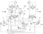
- FIG. 1 is a configuration diagram of a hydraulic drive system according to a first embodiment of the present invention.
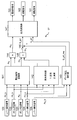
- FIG. 2 is a diagram for explaining control logic of a controller shown in FIG.
- FIG. 3 is a configuration diagram of a reproduction control calculation unit shown in FIG.
- FIG. 2 is an opening area diagram of the regeneration control valve shown in FIG.
- FIG. 2 is a characteristic diagram of the pressure sensor shown in FIG. 3 is a flowchart for explaining a determination process of an abnormality detection unit shown in FIG.
- FIG. 2 is a configuration diagram of a pump flow rate calculation unit shown in FIG.
- FIG. 4 is a configuration diagram of a hydraulic drive system according to a second embodiment of the present invention.
- FIG. 8 is a diagram for explaining control logic of the controller shown in FIG. FIG.
- FIG. 8B is a schematic diagram of the changeover switch shown in FIG. 8A.
- FIG. 8B is a configuration diagram of a playback control calculation unit shown in FIG. 8A.
- FIG. 5 is a configuration diagram of a hydraulic drive system according to a third embodiment of the present invention.
- FIG. 11 is a diagram for explaining control logic of the controller shown in FIG.
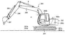
- FIG. 3 is a diagram showing the external appearance of a hydraulic excavator equipped with a hydraulic drive system according to the first to third embodiments of the present invention.
- the hydraulic drive system drives a driven part (boom, arm, etc.) provided in a work machine (hydraulic excavator, etc.) with hydraulic pressure.
- FIG. 12 is an external view of a hydraulic excavator equipped with the hydraulic drive system according to the first to third embodiments of the present invention.
- the hydraulic excavator includes a lower traveling body 201, an upper turning body 202, and a front work machine 203.
- the lower traveling body 201 has left and right crawler type traveling devices 201a and 201b (only one side is shown), and is driven by left and right traveling motors 201c and 201d (only one side is shown).
- the upper turning body 202 is mounted on the lower traveling body 201 so as to be turnable, and is driven to turn by a turning motor 202a.
- the front work machine 203 is attached to the front part of the upper swing body 202 so as to be able to be raised and lowered.
- the upper swing body 202 is provided with a cabin (operator's cab) 202b, and operation devices such as an operation lever and a travel operation pedal device are disposed in the cabin 202b.
- the front work machine 203 has an articulated structure having a boom 205 (first driven body), an arm 206 (second driven body), and a bucket 207.
- the boom 205 is expanded and contracted by a boom cylinder 4 (first hydraulic actuator).
- the arm 206 is rotated in the vertical direction with respect to the upper swinging body 202, and the arm 206 is rotated in the vertical and front-back directions with respect to the boom 205 by the expansion and contraction of the arm cylinder 8 (second hydraulic actuator). By extending and contracting, the arm 206 is rotated up and down and back and forth.
- FIG. 1 is a configuration diagram of a hydraulic drive system 100A according to a first embodiment of the present invention.
- the boom circuit and arm circuit of the excavator are extracted and displayed for easy viewing.
- the hydraulic pump 1 is a variable displacement hydraulic pump that supplies pressure oil to the control valve 5.
- the hydraulic pump 1 is also connected to another actuator (not shown), and the discharge flow rate is controlled by the controller 27 (control device) in accordance with the operation lever of the other actuator.
- the hydraulic pump 2 is a variable displacement hydraulic pump, the discharge flow rate can be controlled by the controller 27, and pressure oil is supplied to the control valve 9. Pressure oil from the hydraulic pump 1 is transmitted to the bottom side of the boom cylinder 4 via the control valve 5 and the bottom side pipe line 15. Further, the pressure oil from the pump 1 is transmitted to the rod side of the boom cylinder 4 through the control valve 5 through the rod side pipe line 13.
- the hydraulic pump 1 and the hydraulic pump 2 constitute a hydraulic pump device 51.
- the hydraulic pump device 51 supplies pressure oil to the boom cylinder 4 (first hydraulic actuator) and the arm cylinder 8 (second hydraulic actuator).
- the hydraulic pumps 1 and 2 are provided with regulators 1a and 2a, respectively, and the tilt angle (capacity) of the hydraulic pumps 1 and 2 is controlled by controlling the regulators 1a and 2a by a control signal from the controller 27, so that the discharge flow rate is Be controlled.
- the pilot valve 7 attached to the operation lever 6 generates a pilot pressure corresponding to the operation amount of the operation lever 6.
- the pilot pressure Pu_b generated by the raising side operation is transmitted to the operation port 5a of the control valve 5 through the raising side pilot pipeline, and the control valve 5 is switched and controlled according to the pilot pressure. .
- the pilot pressure Pd_b generated by the lower side operation is transmitted to the operation port 5b of the control valve 5 through the lower side pilot pipeline, and the control valve 5 is switched and controlled according to the pilot pressure. . Further, the pilot pressure Pd_b is also transmitted to the communication control valve 16, and the communication control valve 16 is switched and controlled.
- the operating lever 6 and the pilot valve 7 constitute a first operating device 41 for operating the boom cylinder 4 (first hydraulic actuator).
- the control valve 5 adjusts the flow rate of return oil from the boom cylinder 4 (first hydraulic actuator).
- the bottom pipeline 15 of the boom cylinder 4 is provided with a communication pipeline 14 that regenerates the bottom pressure oil into a rod, and the communication pipeline 14 is provided with a communication control valve 16.
- the communication control valve 16 is operated by the pilot pressure Pd_b, and when the communication control valve 16 is opened, the pressure oil of the boom cylinder 4 is sent to the rod to prevent negative pressure of the rod.
- the bottom side pipe line 15 is further provided with a regeneration control valve 17 for regenerating the oil discharged from the boom cylinder 4 to the outlet of the hydraulic pump 2, with the port on one side regenerating to the control valve 5 and the other side regenerating. It is connected to the side pipe line 18.
- the regeneration control valve 17 (regeneration valve), the regeneration side pipe 18 (regeneration passage), and the electromagnetic proportional valve 22 (first solenoid valve) return oil from the boom cylinder 4 (first hydraulic actuator) to the arm cylinder.
- a regenerating device 61 for supplying to 8 (second hydraulic actuator) is configured.
- the regeneration control valve 17 of the regeneration device 61 is a direction control having a port for supplying return oil from the boom cylinder 4 to the arm cylinder 8 and a port for discharging the return oil from the boom cylinder 4 to the control valve 5. It is a valve. Thereby, for example, the regeneration flow rate and the bleed flow rate can be controlled collectively.
- the pressure oil from the hydraulic pump 2 is transmitted to the rod side via the control valve 9 and the bottom side pipe line 20 via the bottom side of the arm cylinder 8 and the rod side pipe line 21.
- the pilot valve 11 attached to the operation lever 10 generates a pilot pressure corresponding to the operation amount of the operation lever 10.
- the pilot pressure Pc_a generated by operating the operation lever 10 to the cloud side is transmitted to the operation port 9a of the control valve 9 via the cloud side pilot conduit, and the control valve 9 is switched and controlled according to the pilot pressure. Is done.
- the pilot pressure Pd_a generated by the dump side operation is transmitted to the operation port 9b of the control valve 9 via the dump side pilot pipe, and the control valve 9 is switched and controlled according to the pilot pressure. .
- the operating lever 10 and the pilot valve 11 constitute a second operating device 42 for operating the arm cylinder 8 (second hydraulic actuator).
- a relief valve 19 is provided.
- the electromagnetic proportional valve 22 operates in accordance with a control signal from the controller 27, converts the pressure oil supplied from the pilot pump 3 into a desired Pi pressure, leads it to the regeneration control valve 17, and controls the opening degree.
- the pilot-side pilot pressure Pu_b and the pilot-side pilot pressure Pd_b of the pilot valve 7 are detected by pressure sensors 28 and 23, the bottom pressure Pb_b of the boom cylinder 4 is detected by the pressure sensor 25, and the pump pressure is detected by the pressure sensor 26. Input to the controller 27.
- the controller 27 performs control according to the input pilot pressure, bottom pressure, and pump pressure, and outputs a control command to the electromagnetic proportional valve 22, the pump 1, and the pump 2.
- the pilot pressure Pd_b generated from the pilot valve 7 is input to the operation port 5b of the control valve 5 and the communication control valve 16.
- the control valve 5 is switched and the bottom side pipe line 15 is connected to the tank, whereby the bottom pressure oil of the boom cylinder 4 is discharged to the tank and the cylinder is lowered.
- the communication control valve 16 is switched in the same manner to regenerate the pressure oil from the bottom side pipe line 15 to the rod side pipe line 13, and the controller 27 outputs a tilt command to the hydraulic pump 1, whereby the rod side pipe line 13 Further, the pressure oil from the hydraulic pump 1 also flows into the rod side pipe, thereby preventing the rod side pipe line 13 from becoming a negative pressure.
- the pilot pressure Pd_a generated from the pilot valve 11 is input to the operation port 9b of the control valve 9.
- the control valve 9 is switched, the bottom side pipe line 20 is connected to the tank, and the rod side pipe line 21 is connected to the hydraulic pump 2, whereby the bottom pressure oil is discharged to the tank and the pressure oil from the hydraulic pump 2 is By flowing into the side, the arm cylinder 8 performs a reduction operation.
- the controller 27 receives signals from the pressure sensors 23, 24, 25, 26, and 28, and outputs a signal to the electromagnetic proportional valve 22 by a control logic described later.
- the regeneration control valve 17 is controlled by the pressure signal from the electromagnetic proportional valve 22, and the bottom pressure oil of the boom cylinder 4 is regenerated to the arm cylinder 8 via the regeneration control valve 17.
- the pressure sensor 23 or 28 detects the operation amount of the first operation device 41.
- the pressure sensor 24 (second operation amount detector) detects the operation amount of the second operation device 42.
- the pressure sensor 25 (first pressure detector) detects the bottom hydraulic pressure of the boom cylinder 4 (first hydraulic actuator).
- the pressure sensor 26 (second pressure detector) detects the hydraulic pressure supplied from the hydraulic pump device 51.
- the pressure sensors 23, 24, 25, 26, 28 constitute a sensor device 71.
- the pilot pressure Pd_b generated from the pilot valve 7 is input to the operation port 5b of the control valve 5 and the communication control valve 16.
- the control valve 5 is switched, and the communication control valve 16 is switched in the same manner, whereby the pressure oil discharged from the bottom of the boom cylinder 4 is regenerated, and the pressure oil of the hydraulic pump 1 is also changed to the rod of the boom cylinder. It prevents the negative pressure from flowing into the side pipe line 13.
- controller 27 outputs a tilt command to the hydraulic pump 2, and reduces the pump flow rate according to the regeneration flow rate of the regeneration control valve 17, thereby reducing fuel consumption.
- FIG. 2 is a diagram for explaining the control logic of the controller 27 shown in FIG.
- the controller 27 includes a regeneration control calculation unit 141, an abnormality detection unit 142, a pump flow rate calculation unit 143, integrators 144 to 145, a subtractor 146, and an output conversion unit 147.
- the lever operation signal 123 is a signal indicating the operation amount (pilot pressure Pd_b) of the operation lever 6 detected by the pressure sensor 23.
- the bottom pressure signal 125 is a signal indicating the bottom pressure Pb_b of the boom cylinder 4 detected by the pressure sensor 25.
- the pump pressure signal 126 is a signal indicating the pump pressure Pp detected by the pressure sensor 26.
- the lever operation signal 124 is a signal indicating the operation amount (pilot pressure Pd_a) of the operation lever 10 detected by the pressure sensor 24.
- the lever operation signal 128 is a signal indicating the operation amount (pilot pressure Pu_b) of the operation lever 6 detected by the pressure sensor 28.
- the regeneration control calculation unit 141 calculates the target regeneration-side opening area Ar 3 of the regeneration control valve 17 and outputs it to the integrator 144. Further, the target pump reduction flow rate Qr 3 is calculated and output to the integrator 135. Details of the reproduction control calculation unit 141 are shown in FIG. FIG. 3 is a configuration diagram of the playback control calculation unit 141 shown in FIG.
- the reproduction control calculation unit 141 includes function generators 131 to 134 and integrators 135 to 138.
- the function generator 131 calculates the regeneration-side opening area Ar 1 of the regeneration control valve 17 in accordance with the lever operation signal 123 (value: Pd_b).
- An opening area diagram of the regeneration control valve 17 is shown in FIG.
- FIG. 4 is an opening area diagram of the regeneration control valve 17 shown in FIG.
- the spool stroke of the regeneration control valve 17 represents the spool stroke of the regeneration control valve 17, and the vertical axis represents the opening area.
- the spool stroke is minimum, the tank side is open, and the opening area on the regeneration side is closed.
- the stroke is gradually moved to the right, the tank side is closed and the regeneration side opening is opened, so that the pressure oil discharged from the boom bottom flows into the regeneration side pipeline 18. Further, by adjusting the stroke, the opening area on the regeneration side can be changed, and the regeneration flow rate can be controlled.
- the lever operation signal 123 (value: PD_B) is large, by widening the opening area Ar 1 of increasing the stroke of the regeneration control valve 17 reproducing side is controlled so as to increase the playback rate.
- the table of the function generator 131 and the opening area diagram of the regeneration control valve 17 may be adjusted so that the oil discharged on the bottom side of the boom cylinder is equivalent to the case where the oil is not regenerated.
- the function generator 132 obtains the pump reduction flow rate Qr 1 according to the lever operation signal 123 (value: Pd_b).
- the function generator 132 may be set according to the characteristics of the opening area Ar 1 set by the function generator 131. That is, since the regeneration flow rate increases as the opening area Ar 1 output from the function generator 131 increases, it is necessary to set a larger pump reduction flow rate Qr 1 .
- the subtractor 130 calculates a differential pressure between the bottom pressure signal 125 (value: Pb_b) and the pump pressure signal 126 (value: Pp).
- the function generator 133 outputs 1 when the differential pressure exceeds a certain set value, and outputs 0 when the differential pressure is less than or equal to the set value.
- the regeneration-side opening area Ar 1 of the regeneration control valve 17 output from the function generator 131 is determined to be unrecoverable when the differential pressure is lower than the set value, and the regeneration-side opening area Ar
- the integrator 135 calculates so that 2 is set to 0.
- the integrator 135 calculates the regeneration-side opening area Ar 2 to be the value Ar 1 output from the function generator 131.
- the integrator 135 outputs the integrated value of the output value Ar 1 of the function generator 131 and the output value (0 or 1) of the function generator 133 as the reproduction-side opening area Ar 2 .
- the output of the function generator 132 is similar to the pump reduced flow rate Qr 1 output from the function generator 132. If the differential pressure is lower than the set value, it is determined that regeneration is impossible, and the pump reduced flow rate Qr 2 is set to 0. Is calculated by the integrator 136 so as to be set to When the differential pressure is higher than the set value, it is determined that regeneration is possible, and the accumulator 136 calculates the pump reduced flow rate Qr 2 to be the value Qr 1 output from the function generator 132.
- the integrator 136 outputs the integrated value of the output value Qr 1 of the function generator 132 and the output value (0 or 1) of the function generator 133 as the pump reduced flow rate Qr 2 .
- the lever operation signal 124 (value: Pd_a) is input to the function generator 134.
- the function generator 134 outputs 0 when the operation amount (pilot pressure Pd_a) indicated by the lever operation signal 124 is equal to or smaller than a certain value, and outputs 1 when it is equal to or larger than the certain value.
- the lever operation signal 124 that is, the operation amount of the operation lever 10 is low
- the control valve 9 seems to be closed, and even if the regeneration side opening area of the regeneration control valve 17 is opened, the flow rate hardly flows to the arm rod side.
- the lever operation signal 124 is sufficiently high, the control valve 9 is open and the regeneration flow rate can flow sufficiently. Therefore, the function generator 134 determines whether or not playback is possible according to the lever operation signal 124 (value: Pd_a).
- the regeneration-side opening area Ar 1 of the regeneration control valve 17 output from the function generator 131 is determined to be unreproducible when the lever operation signal 124 (value: Pd_a) is lower than the set value.
- the integrator 137 calculates so that the reproduction-side opening area Ar 3 is set to zero. If the lever operation signal 124 (value: Pd_a) is higher than the set value, it is determined that reproduction is possible, and the reproduction-side opening area Ar 3 is set to the value output from the function generator 131 by the integrator 137. Calculated.
- the integrator 137 outputs the integrated value Ar 3 of the output value Ar 2 of the integrator 135 and the output value (0 or 1) of the function generator 134 as the target reproduction-side opening area 139.
- the output of the function generator 132 determines that the pump reduction flow rate Qr 1 output from the function generator 132 cannot be regenerated when the lever operation signal 124 (value: Pd_a) is lower than the set value.
- the integrator 138 calculates so that the pump reduction flow rate Qr 3 is set to 0.
- the accumulator 138 calculates the pump reduced flow rate Qr 3 so as to be the value output from the function generator 132.
- the integrator 138 outputs the integrated value Qr 3 of the output value Qr 2 of the integrator 136 and the output value (0 or 1) of the function generator 134 as the target pump reduced flow rate 140.
- the output Ar 3 of the integrator 137 is output as the target regeneration side opening area 139, and the output Qr 3 of the integrator 138 is output as the target pump reduced flow rate 140.
- the abnormality detection unit 142 inputs each sensor signal and determines whether the sensor signal is normal or abnormal, and outputs 1 to the integrators 144 and 145 if normal or 0 if abnormal. .
- FIG. 5A is a characteristic diagram of the pressure sensor shown in FIG.
- FIG. 5B is a flowchart for explaining the determination process of the abnormality detection unit 142 shown in FIG.
- the horizontal axis indicates the pressure input to the pressure sensor
- the vertical axis indicates the output voltage of the pressure sensor.
- the output voltage for the minimum pressure Pmin determined by the specifications of the pressure sensor is Emin
- the output voltage for the maximum pressure Pmax is Emax.
- the normal output voltage Emin is set to a value higher than 0V
- the output voltage Emax is set to a value lower than the power supply voltage.
- the output voltage will be 0V or near the power supply voltage, and a voltage outside the range of Emin and Emax will be output.
- the abnormality detection unit 142 determines that an abnormality occurs when the output voltage deviates from Emin and Emax, and outputs 0 to the integrators 144 and 145 when any of the sensors is determined to be abnormal. 1 is output.
- the abnormality detection unit 142 determines that there is an abnormality when the electric signal output from the pressure sensor becomes smaller than a preset lower limit value Emin or becomes larger than a preset upper limit value Emax. Thereby, the abnormality of the sensor device 71 can be determined with a simple configuration.
- Emax and Emin may be set for each pressure sensor.
- the lower limit output voltage Emin1 corresponding to the lower limit pressure Pmin1 is set for the pressure sensors 23 and 24 for detecting the pilot pressure output from the first operating device 41 and the second operating device 42, and the upper limit pressure Pmax1 is supported.
- the upper limit output voltage Emax1 is supported.
- the lower limit output voltage Emin2 corresponding to the lower limit pressure Pmin2 is set for the pressure sensor 25 for detecting the hydraulic pressure on the bottom side of the boom cylinder 4 and the pressure sensor 26 for detecting the pump pressure, and the upper limit corresponding to the upper limit pressure Pmax2.
- the determination process of the abnormality detection unit 142 will be described with reference to FIG. 5B.
- the abnormality detection unit 142 executes the following process using a predetermined cycle as a trigger.
- the abnormality detection unit 142 sets a target pressure sensor (step S10).
- the abnormality detection unit 142 determines whether or not the output voltage E of the pressure sensor is greater than the maximum voltage Emax (step S15).
- the abnormality detection unit 142 determines that the sensor device 71 including this pressure sensor is abnormal (failure) (step S35).
- the abnormality detection unit 142 proceeds with the process to step S20.
- the abnormality detection unit 142 determines whether or not the output voltage E of the pressure sensor is smaller than the minimum voltage Emin (step S20). If the abnormality detection unit 142 determines that the output voltage E of the pressure sensor is smaller than the minimum voltage Emin (step S20; YES), the abnormality detection unit 142 determines that the sensor device 71 is abnormal. On the other hand, if the abnormality detection unit 142 determines that the output voltage E of the pressure sensor is greater than the minimum voltage Emin (step S20; NO), the process proceeds to step S25.
- the abnormality detection unit 142 determines whether or not the index of the pressure sensor is smaller than n (step S25). If the index of the pressure sensor is n, the abnormality detection unit 142 proceeds to step S30. Here, when the output voltages E of all the pressure sensors are within a predetermined voltage range (Emin ⁇ E ⁇ Emax), the process proceeds to step S30.
- the abnormality detection unit 142 determines that the sensor device 71 is normal (no failure) (step S30), and ends the process. As described above, the abnormality detection unit 142 outputs 1 when determined to be normal, and outputs 0 when determined as abnormal.
- the abnormality detection unit 142 determines that each sensor signal is normal, the signal input from the reproduction control calculation unit 141 to the integrator 144 or 145 is output as it is, and the abnormality detection unit 142 Is determined to be abnormal, it is multiplied by 0 output from the abnormality detection unit 142, so that a 0 signal is output from the integrator 144 or 145.
- the target regeneration side opening area Ar 4 and the target pump reduction flow rate Qr 4 of the regeneration control valve 17 are 0, and the boom cylinder 4 is armed.
- the regeneration to the cylinder 8 is canceled, and the control for reducing the discharge flow rate of the hydraulic pump 2 is also canceled by a regeneration flow rate described later.
- the pump flow rate calculation unit 143 controls the flow rate of the hydraulic pump 1 according to the lever operation signals 123 and 128, and executes control logic for controlling the flow rate of the hydraulic pump 2 according to the lever operation signal 124. Details are shown in FIG. FIG. 6 is a configuration diagram of the pump flow rate calculation unit 143 shown in FIG.
- the pump flow rate calculation unit 143 includes function generators 151 to 153 and a maximum value selector 154.
- the lever operation signal 124 is input to the function generator 151, and the function generator 151 outputs the hydraulic pump 2 required flow rate 155 so that the pump flow rate Q_p2_req corresponding to the lever operation is obtained.
- the function generator 151 has a characteristic such that a minimum flow rate is output from the hydraulic pump 2 when the lever operation signal 124 (value: Pd_a) is not input. This is to improve the response when the operation lever is inserted and to prevent seizure of the hydraulic pump.
- the lever operation signal 124 rises, the flow rate of the hydraulic pump 2 is increased accordingly, and the pressure oil flowing into the arm cylinder 8 is increased. As a result, the arm cylinder speed according to the operation amount is obtained.
- the lever operation signal 123 (value: Pd_b) is input to the function generator 152, and the lever operation signal 128 (value: Pu_b) is input to the function generator 153.
- the function generators 152 and 153 output the flow rates Qd_p1 and Qu_p1 of the hydraulic pump 1 according to the boom lowering operation and the raising operation to the maximum value selector 154, respectively.
- the function generators 152 and 153 have characteristics such that a minimum flow rate is output from the hydraulic pump 1 when no lever operation signal is input.
- the lever operation signal rises, the flow rate of the hydraulic pump 1 is increased accordingly, and the pressure oil flowing into the boom cylinder 4 is increased.
- the boom cylinder speed according to the operation amount is obtained.
- the function generator 152 has a characteristic that the increase in the flow rate corresponding to the lever operation signal is smaller than that of the function generator 153.
- the lever operation signal 123 (value: Pd_b) is a boom lowering operation signal, and a small amount of flow is sent from the hydraulic pump 1 to the boom cylinder 4 during the boom lowering operation. That is, during boom lowering operation, it is necessary to send pressure oil from the hydraulic pump 1 so that the rod of the boom cylinder 4 does not become negative pressure, but the communication control valve 16 is flowing pressure oil from the bottom to the rod, Furthermore, the rod area is about half of the bottom area, and a large flow rate is not required compared to the boom raising operation.
- the maximum value selector 154 outputs the larger one of the output values Qd_p1 and Qu_p1 of the function generators 152 and 153 as the hydraulic pump 1 target flow rate 156 (value: Q_p1).
- the subtractor 146 receives the hydraulic pump 2 required flow rate Q_p2_req and the target pump reduced flow rate Qr 4 and subtracts the hydraulic pump 2 target flow rate, that is, the regeneration flow rate Qr 4 minutes, from the hydraulic pump 2 required flow rate Q_p2_req. And output from the subtractor 146 as the hydraulic pump 2 target flow rate Q_p2.
- the output conversion unit 147 receives the output Ar 4 of the integrator 144, the output Q_p2 of the subtractor 146, and the hydraulic pump 1 target flow rate 156 (value: Q_p1) from the pump flow rate calculation unit 143. Are output as a solenoid valve command 122, a tilt command 102 to the hydraulic pump 2, and a tilt command 101 to the hydraulic pump 1.
- the electromagnetic proportional valve 22 is controlled, and the regeneration control valve 17 is controlled to a desired opening area by the driving pressure output from the electromagnetic proportional valve 22.
- the hydraulic pump 2 is controlled to a desired tilt by the tilt command 102, and the pump flow rate with a reduced regenerative flow rate is discharged.
- the hydraulic pump 1 is controlled to a desired tilt by the tilt command 101, and the flow rate is sent to the boom cylinder 4.
- a differential pressure is calculated from the bottom pressure signal 125 (value: Pb_b) and the pump pressure signal 126 (value: Pp) through the subtractor 130, and the function generator 133 determines whether or not regeneration is possible.
- the function generator 134 determines whether or not playback is possible from the lever operation signal 124 (value: Pd_a).
- the regeneration-side opening area Ar 1 of the regeneration control valve 17 output from the function generator 131 is the integrator.
- the pump reduction flow rate Qr 1 output as the target regeneration side opening area 139 (value: Ar 3 ) via 135 and 137 and output from the function generator 132 is reduced to the target pump via the integrators 136 and 138.
- the abnormality detection unit 142 determines whether each sensor signal is normal or abnormal. If it is determined to be normal, 1 is output to the integrators 144 and 145 if 1 is determined to be abnormal.
- the target regeneration side opening area Ar 4 and the target pump reduction flow rate Qr 4 are set to zero.
- the subtractor 146 receives the hydraulic pump 2 required flow rate Q_p2_req and the target pump reduced flow rate Qr 4 from the pump flow rate calculation unit 143, and the pump flow rate is reduced by the regeneration flow rate Qr 4 minutes to output the hydraulic pump 2 target flow rate Q_p2. .
- the target regeneration side opening area Ar 4 , the hydraulic pump 2 target flow rate Q_p2, and the hydraulic pump 1 target flow rate Q_p1 are converted respectively, and the electromagnetic valve command 122, the tilt command 102, and the tilt command 101 are respectively converted into electromagnetic Output to the proportional valve 22, the hydraulic pump 2, and the hydraulic pump 1.
- the abnormality detection unit 142 determines that each sensor is normal, the target regeneration side opening area 139 and the target pump reduced flow rate 140 are output as they are, and the desired regeneration control valve opening area and pump Since the flow rate is controlled, the oil discharged from the boom cylinder 4 is controlled and adjusted by the regeneration control valve 17, passed through the regeneration side pipe 18, and regenerated to the hydraulic pump 2.
- the pump flow rate is reduced by the regenerative flow rate to achieve the desired speed desired by the operator, and the fuel consumption is improved by reducing the pump flow rate.
- the abnormality detection unit 142 When any one of the sensors is determined to be abnormal by the abnormality detection unit 142, the abnormality detection unit 142 performs an operation so that the target regeneration side opening area 139 and the target pump reduction flow rate 140 are zero. As a result, the regeneration control valve 17 is not switched, the speed is adjusted by the opening area of the control valve 5 corresponding to the operation lever 6, and the flow rate of the hydraulic pump 2 is also a flow rate corresponding to the operation lever 10, so that the operator Adjusted to the desired speed.
- the controller 27 supplies the return oil from the boom cylinder 4 (first hydraulic actuator) to the arm cylinder 8. It functions as a first control unit that controls the regeneration device 61 so as to be supplied to the (second hydraulic actuator). In addition, when the sensor device 71 is abnormal, the controller 27 (first control unit) supplies the return oil from the boom cylinder 4 to the arm cylinder 8 even if the value detected by the sensor device 71 satisfies the regeneration condition. The playback device 61 is controlled so as not to be supplied.
- the regeneration condition is a condition required when the return oil from the boom cylinder 4 is supplied to the arm cylinder 8.
- the controller 27 reproduces the flow rate for supplying the return oil from the boom cylinder 4 to the arm cylinder 8 when the sensor device 71 is normal and the value detected by the sensor device 71 satisfies the regeneration condition. It functions as a second control unit that controls the hydraulic pump device 51 so as to reduce the discharge flow rate of the hydraulic pump device 51 according to the flow rate.
- the controller 27 cancels the control for reducing the discharge flow rate of the hydraulic pump device 51 even if the value detected by the sensor device 71 satisfies the regeneration condition. To do.
- the target regeneration side opening area 139 and the target pump reduction flow rate 140 are output as they are as the electromagnetic valve command 122 and the tilt command 102 via the output conversion unit 147.
- the regeneration control valve 17 is switched and the flow rate of the hydraulic pump 2 is further reduced, so that the pressure oil at the boom bottom is regenerated to the arm rod, the boom cylinder is inadvertently lowered, and the speed of the arm cylinder 8 is It will change.
- the target regeneration side opening area 139 and the target pump reduced flow rate 140 are respectively set. Set to 0.
- the output from the proportional solenoid valve 22 based on the solenoid valve command 122 can be suppressed, so that the regeneration control valve 17 can be prevented from being inadvertently switched, and the boom cylinder can be prevented from dropping at an unexpected speed. I can do it.
- the tilt command 102 becomes an output corresponding to the hydraulic pump required flow rate 155. Therefore, since the flow rate of the hydraulic pump 2 does not change carelessly, the speed of the arm cylinder 8 can be set to a desired speed desired by the operator.
- the arm rod pressure is higher than the boom bottom pressure during the boom lowering arm dumping operation.
- the arm rod pressure is higher than the boom bottom pressure, so control is performed so that the regeneration control valve is not opened, but if it is determined that the boom bottom pressure is higher due to an abnormality in the boom bottom pressure sensor, regeneration control calculation is performed.
- the function generator 133 in the unit 141 outputs a target reproduction-side opening area 139 in order to output 1 for determining that reproduction is possible.
- the target regeneration side opening area 139 is output as it is as the electromagnetic valve command 122 via the output conversion unit 147, and the regeneration control valve 17 is switched.
- the arm rod pressure is actually higher than the boom bottom pressure, so even if the regeneration control valve is opened, it does not flow from the boom bottom to the arm rod, and the tank passage is throttled, so it is discharged from the boom bottom.
- the boom cylinder suddenly decelerates and stops suddenly, making the operability uncomfortable.
- the target regeneration-side opening area 139 is set to 0 by outputting 0 to the integrator 144 from the abnormality detection unit 142.
- the output from the electromagnetic valve command 122 is suppressed and the regeneration control valve 17 is not switched unintentionally, so that sudden deceleration and sudden stop can be prevented.
- each actuator is controlled at a speed desired by the operator regardless of whether each sensor is normal or abnormal.
- FIG. 7 is a configuration diagram of a hydraulic drive system 100B according to the second embodiment of the present invention. The description of the same parts as those in the first embodiment will be omitted.
- the regeneration control valve 17 having a port on each of the control valve 5 and the regeneration side pipe line 18 in the first embodiment adjusts only the flow rate of the regeneration side pipe line 18 in the second embodiment. It is valve 30. Further, a normally open electromagnetic proportional valve 31 for reducing the lower pilot pressure Pd_b of the pilot valve 7 is disposed and controlled by the controller 27.
- the regeneration side pipe 18 (regeneration passage), the regeneration control valve 30 (regeneration valve), the electromagnetic proportional valve 22 (first electromagnetic valve), and the electromagnetic proportional valve 31 (second electromagnetic valve) Configure 61.
- the regeneration side pipe 18 supplies the return oil from the boom cylinder 4 (first hydraulic actuator) to the arm cylinder 8 (second hydraulic actuator).
- the regeneration control valve 30 adjusts the flow rate of the pressure oil in the regeneration side pipeline 18.
- the electromagnetic proportional valve 22 hydraulically controls the regeneration control valve 30.
- the normally open electromagnetic proportional valve 31 receives a first pilot pressure corresponding to the operation amount of the first operating device 41, outputs a second pilot pressure obtained by reducing the first pilot pressure to the control valve 5, 2 Control valve 5 is controlled by pilot pressure.
- the pilot pressure Pd_a generated from the pilot valve 11 is input to the operation port 9b of the control valve 9.
- the control valve 9 is switched, the bottom side pipe line 20 is connected to the tank, and the rod side pipe line 21 is connected to the hydraulic pump 2, whereby the bottom pressure oil is discharged to the tank and the pressure oil from the hydraulic pump 2 is By flowing into the side, the arm cylinder 8 performs a reduction operation.
- the controller 27 receives the signals from the pressure sensors 23, 24, 25, 26, and 28, and outputs the signals to the electromagnetic proportional valves 22 and 31 by the control logic described later.
- the regeneration control valve 30 (regeneration valve) is controlled by the pressure signal from the electromagnetic proportional valve 22, and the bottom pressure oil of the boom cylinder 4 is regenerated to the arm cylinder 8 via the regeneration control valve 30.
- the pilot pressure Pd_b is moderately reduced by the electromagnetic proportional valve 31, and the control valve 5 is throttled and adjusted.
- the controller 27 when the sensor device 71 is normal and the value detected by the sensor device 71 satisfies the regeneration condition, the controller 27 is configured to reduce the first pilot pressure so as to reduce the first pilot pressure. It functions as a third control unit for controlling the solenoid valve. In addition, when the sensor device 71 is abnormal, the controller 27 (third control unit) electromagnetically prevents the first pilot pressure from being reduced even if the value detected by the sensor device 71 satisfies the regeneration condition. The proportional valve 31 is controlled.
- the bleed flow rate discharged to the tank is reduced by the amount regenerated through the regeneration control valve 30, and the boom cylinder 4 is adjusted to a desired speed desired by the operator.
- the regeneration control valve 30 and the control valve 5 can be controlled separately compared to the first embodiment, so that the regeneration flow rate and the bleed flow rate are finely controlled, and the fuel consumption reduction effect is further improved. can do.
- the pilot pressure Pd_b generated from the pilot valve 7 is input to the communication control valve 16 so that the pressure oil discharged from the bottom of the boom cylinder 4 is regenerated, and the pressure oil from the hydraulic pump 1 is also This prevents the negative pressure from flowing into the rod-side pipe line 13.
- controller 27 outputs a tilt command to the hydraulic pump 2, and reduces the pump flow rate according to the regeneration flow rate of the regeneration control valve 30, thereby reducing fuel consumption.
- FIG. 8A is a diagram for explaining the control logic of the controller 27 shown in FIG.
- FIG. 8B is a schematic diagram of the changeover switch 81 shown in FIG. 8A.
- the regeneration control calculation unit 141 is arranged on the target tank side in addition to the target regeneration side opening area Ar 11 and the target pump reduced flow rate Qr 12 supplied to the integrator 144 and the integrator 145, respectively.
- FIG. 9 is a configuration diagram of the playback control calculation unit 141 shown in FIG. 8A.
- the lever operation signal 123 value: Pd_b
- the bottom pressure signal 125 value: Pb_b
- the target bottom flow rate Qb_b increases in proportion to the lever operation signal 123, and has a characteristic that the inclination becomes steep as the pressure (Pb_b) increases.
- the output (value: Pd_a) of the lever operation signal 124 is input to the function generator 160, and the required flow rate Q_p2_req of the hydraulic pump 2 is calculated. That is, the characteristic of the function generator 160 is the same as that of the function generator 151 of FIG. 6 shown in the first embodiment.
- the target bottom flow rate Qb_b output from the function generator 158 and the required flow rate Q_p2_req of the hydraulic pump 2 output from the function generator 160 are input to the minimum value selector 161, and the smaller of the input signals is set as the target regeneration flow rate Qr. Decide as 11 .
- the smaller one of the target bottom flow rate Qb_b and the required flow rate Q_p2_req of the hydraulic pump 2 is selected because the regenerative flow rate becomes larger than the flow rate of the hydraulic pump 2 that is going to be released from the original. This is because the arm cylinder 8 is moved faster than the normal hydraulic pump 2 and the operability is deteriorated.
- the subtractor 157 calculates a differential pressure between the bottom pressure Pb_b indicated by the bottom pressure signal 125 and the pump pressure Pp indicated by the pump pressure signal 126, and supplies the differential pressure to the output determination unit 159.
- the differential pressure based on the bottom pressure signal 125 and the pump pressure signal 126 is input to the output determination unit 159 (function generator).
- the output determination unit 159 outputs 1 when the differential pressure exceeds a certain set value, and outputs 0 when the differential pressure is less than or equal to the set value.
- the output determination unit 159 outputs 1 when the bottom pressure signal 125 (value: Pb_b) is higher than the pump pressure signal 126 (value: Pp), and outputs 0 when the pump pressure signal 126 is higher. Output to the device 163.
- the integrator 163 is input the output of the target playback rate Qr 11 and the output determination unit 159 (0 or 1), if the direction of the bottom pressure Pb_b is high and outputs the target playback rate Qr 11, is better in the pump pressure Pp If it is high, 0 is output.
- a 0 signal is output and a command is sent so as not to operate.
- the differential pressure (Pb_b-Pp) based on the target regeneration flow rate Qr 12 , the bottom pressure signal 125 (value: Pb_b) and the pump pressure signal 126 (value: Pp) calculated by the integrator 163 is input to the opening area calculation unit 165.
- the target regeneration-side opening area 139 (value: Ar 11 ) of the regeneration control valve 30 is calculated from the orifice equation (1).
- the target regeneration flow rate Qr 12 output from the integrator 163 is output as the target pump reduced flow rate 140.
- the controller 27 (second control unit) is discharged from the bottom side of the boom cylinder 4 in accordance with the operation amount Pd_b of the first operating device 41 and the hydraulic pressure Pb_b on the bottom side of the boom cylinder 4 (first hydraulic actuator).
- the minimum value of the target bottom flow rate Qb_b indicating the flow rate of the pressure oil to be supplied and the pump request flow rate Q_p2_req indicating the flow rate of the pressure oil to be supplied to the arm cylinder 8 according to the operation amount Pd_a of the second operating device 42 is set.
- the regeneration flow rate Qr 12 is calculated based on the minimum value Qr 11 selected.
- the output of the regeneration control calculation unit 141 includes the target tank side opening area 166 (value: At 1 ), the target regeneration side opening area 139 (value: Ar 11 ), and the target pump reduction flow rate 140 (value: Qr 12 ). Respectively.
- a changeover switch 81 and a maximum value selector 150 are further added, and the maximum value selector 150 includes the target tank side opening area At 1 output from the regeneration control calculation unit 141 and The output value of the changeover switch 81 is input.
- the changeover switch 81 outputs 0 to the maximum value selector 150 when 1 (normal) is input from the abnormality detection unit 142.
- the changeover switch 81 outputs the maximum opening area At_max of the control valve 5 to the maximum value selector 150.
- the maximum opening area At_max is always output from the maximum value selector 150 regardless of the output At 1 of the regeneration control calculation unit 141.
- the abnormality detection unit 142 determines that the value is normal, the value At 1 calculated by the reproduction control calculation unit 141 is output from the maximum value selector 150 as it is.
- the electromagnetic proportional valve 31 is a normally open type electromagnetic proportional valve
- the electromagnetic valve command 231 when the electromagnetic valve command 231 is 0, that is, when the current is 0, the lowered pilot pressure Pd_b is reduced by the electromagnetic proportional valve 31.
- the pressure signal is applied to the control valve 5 as it is.
- the electromagnetic valve command 231 increases, that is, when the current increases, the lowered pilot Pd_b is decompressed by the electromagnetic proportional valve 31, so that the opening degree of the control valve 5 is reduced.
- the target tank side opening area At 1 As shown in FIG. 9, in the regeneration control calculation unit 141, the target tank side opening area At 1 , the target pressure side signal 123, the bottom pressure signal 125, the pump pressure signal 126, and the various signals from the lever operation signal 124.
- the regeneration side opening area Ar 11 and the target pump reduction flow rate Qr 12 are calculated.
- the target regeneration-side opening area Ar 11 regenerates the hydraulic oil discharged from the boom cylinder 4 to the hydraulic pump 2 as much as possible, and the flow rate flowing into the arm cylinder 8 does not become larger than the flow rate when not regenerating. Control adjusted.
- the target tank side opening area At 1 is controlled and adjusted so that the flow rate discharged from the boom cylinder 4 does not change between when the regeneration is performed and when it is not regenerated.
- the calculated regenerative flow rate Qr 12 is output as the target pump reduced flow rate.
- the outputs are converted by the output conversion unit 147 via the integrators 144 and 145, the changeover switch 81, the maximum value selector 150, and the subtractor 146, and the target tank side opening area At 2 is as an electromagnetic valve command 231, the target playback side opening area Ar 12 as the solenoid valve command 122, the hydraulic pump 2 target flow rate Q_p2 as tilting command 102, the hydraulic pump 1 target flow rate Q_p1 is output as a tilting command 101.
- the target tank side opening area At 1 calculated by the regeneration control calculation unit 141 the target regeneration side opening is calculated by outputting 1 to the integrators 144 and 145 and the changeover switch 81.
- the area Ar 11 and the target pump reduced flow rate Qr 12 are output as they are. Therefore, the regeneration control valve 30 is controlled by the electromagnetic proportional valve 22, and the control valve 5 is controlled and adjusted by the electromagnetic proportional valve 31, and the oil discharged from the boom cylinder 4 is regenerated to the hydraulic pump 2 to the maximum, and the speed of the boom cylinder 4 is increased. Control valve 5 is controlled to keep.
- the subtracter 146 reduces the hydraulic pump 2 target flow rate, that is, the regeneration flow rate Qr 13 minutes, from the hydraulic pump 2 required flow rate Q_p2_req. As a result, the flow rate of the hydraulic pump 2 is reduced by the regeneration flow rate, and fuel consumption can be reduced.
- the maximum pilot area At_max is input from the changeover switch 81 to the maximum value selector 150, whereby the lowered pilot pressure Pd_b input to the electromagnetic proportional valve 31 is reduced. Instead, it is added to the control valve 5 as it is, and the opening area is adjusted according to the operation amount of the operation lever 6.
- the regeneration control valve 30 remains closed, and all oil discharged from the boom cylinder 4 flows to the tank via the control valve 5. Since the control valve 5 has an opening area corresponding to the operation lever 6, the speed of the boom cylinder 4 is adjusted to a speed desired by the operator.
- the flow rate of the hydraulic pump 2 also becomes a flow rate corresponding to the operation amount of the operation lever 10, and is adjusted to the arm cylinder speed desired by the operator.
- the oil discharged from the boom cylinder 4 is finely controlled and adjusted by the control valve 5 via the regeneration control valve 30 and the electromagnetic proportional valve 31, so that the first embodiment and In comparison, the discharged oil can be regenerated as much as possible, and the speed of the boom cylinder 4 can be maintained at the speed desired by the operator. Then, by reducing the flow rate of the hydraulic pump 2 by the regenerative flow rate, the arm speed desired by the operator is adjusted, and the fuel consumption can be further reduced.
- the speed of the actuator is adjusted to the speed desired by the operator regardless of whether the sensor is normal or abnormal.
- FIG. 10 is a configuration diagram of a hydraulic drive system 100C according to the third embodiment of the present invention. The description of the same parts as those in the first embodiment will be omitted.
- the regeneration control valve 17 is configured to close the regeneration side during normal operation, whereas in the third embodiment, the regeneration control valve 32 is configured to normally operate the regeneration side. The difference is in the open configuration.
- the controller 27 sends the output from the electromagnetic proportional valve 22 to the regeneration control valve 32 during the normal boom lowering operation in which the pressure oil of the boom cylinder 4 is not regenerated in the arm cylinder 8, thereby switching the boom cylinder.
- the pressure oil discharged from the bottom of 4 is sent to the control valve 5 and the arm cylinder 8 is controlled not to regenerate the pressure oil.
- the controller 27 controls the output of the electromagnetic proportional valve 22 so that the pressure oil discharged from the boom cylinder 4 is regenerated to the arm cylinder 8 via the regeneration control valve 32.
- the regeneration side pipe 18 (regeneration passage), the regeneration control valve 32 (regeneration valve), and the electromagnetic proportional valve 31 (second solenoid valve) constitute a regeneration device 61.
- FIG. 11 is a diagram for explaining the control logic of the controller 27 shown in FIG. Note that the description of the same parts as in FIG. 2 shown in the first embodiment is omitted.
- the target regeneration side opening area 139 (value: Ar 3 ) calculated by the regeneration control calculation unit 141 is input to the function generator 167 via the integrator 144.
- the function generator 167 shows the relationship between the regeneration-side opening area Ar 4 of the regeneration control valve 32 and the control pressure output from the electromagnetic proportional valve 22. That is, the maximum control pressure for switching the regeneration control valve 32 is output when the regeneration opening area of the regeneration control valve 32 is closed, and the regeneration control valve 32 is switched when the regeneration opening area is fully opened. Therefore, the minimum control pressure is output.
- the output conversion unit 168 outputs the control pressure output from the function generator 167 to the electromagnetic proportional valve 22 as the electromagnetic valve command 122.
- the target regeneration side opening area 139 is output when all the regeneration conditions are satisfied.
- the abnormality detection unit 142 determines whether each sensor signal is normal or abnormal. If it is determined to be normal, 1 is output to the integrator 144 if 1 is determined to be abnormal.
- the target regeneration side opening area is set to zero.
- the function generator 167 receives the target regeneration-side opening area output from the integrator 144, and outputs a control pressure at which the regeneration-side opening area of the regeneration control valve 32 has a desired value.
- the output conversion unit 168 outputs the control pressure output from the function generator 167 to the electromagnetic proportional valve 22 as the electromagnetic valve command 122.
- the control pressure that becomes the target regeneration side opening area 139 is output as it is, and is controlled to the opening area of the desired regeneration control valve.
- the oil discharged from the boom cylinder 4 is controlled and adjusted by the regeneration control valve 17 and is regenerated to the hydraulic pump 2 through the regeneration side pipe 18.
- the function generator 167 When any one of the sensors is determined to be abnormal by the abnormality detection unit 142, the function generator 167 performs maximum control by performing an operation from the abnormality detection unit 142 so that the target reproduction-side opening area 139 is zero. Pressure is output. As a result, the regeneration control valve 17 is switched, the speed is adjusted by the opening area of the control valve 5 corresponding to the operation lever 6, and the speed desired by the operator is adjusted.
- the present invention is not limited to the above-described embodiment, and includes various modifications.
- the above-described embodiments describe the present invention in an easy-to-understand manner, and are not necessarily limited to those having all the configurations described.
- a part of the configuration of an embodiment can be replaced with the configuration of another embodiment, and the configuration of another embodiment can be added to the configuration of an embodiment.
- the pressure sensor 26 is provided at the outlet of the hydraulic pump, but may be provided on the rod side of the arm cylinder 8. That is, it is only necessary to detect the pressure between the hydraulic pump 2 and the arm cylinder 8.
- the number of hydraulic pumps constituting the hydraulic pump device 51 is two, but is not limited to this, and may be one.
- the controller 27 (second control unit) indicates that the sensor device 71 is normal and the value detected by the sensor device 71 satisfies the regeneration condition.
- the hydraulic pump is controlled to reduce the discharge flow rate of the hydraulic pump in accordance with the regeneration flow rate.
- the flow rate supplied from the hydraulic pump to the rod side 13 of the boom cylinder 4 also decreases, but the opening of the communication control valve 16 is widened to ensure a sufficient flow rate from the bottom of the boom cylinder 4 to the rod. For example, supply from the hydraulic pump is almost unnecessary and does not affect operability.
- the operation amount of the operation lever 6 is detected by the pressure sensor 23 or 28, but is not limited thereto, and may be, for example, a resistance position sensor.
- the operation amount of the operation lever 10 is the same.
- the first manipulated variable detector (23 or 28), the second manipulated variable detector (24), the first pressure detector (25), and the second pressure detector (26) are detected pressures.
- the type of the pressure sensor is not limited to this.
- the pressure sensor may detect the hydraulic pressure using hydraulic logic.
- the pressure oil of the hydraulic pump 1 flows into the rod side conduit 13 during the boom lowering operation, but the meter-in of the control valve 5 may be closed so that it does not flow.
- each of the above-described configurations, functions, and the like may be realized by software by interpreting and executing a program that realizes each function by the processor.
- Information such as programs, tables, and files for realizing each function can be stored in a recording device such as a memory, a hard disk, or an SSD (Solid State Drive), or a recording medium such as an IC card, an SD card, or a DVD.
- Controller (control device, first control unit, second control unit, third control unit) 28 ... Pressure sensor (first operation amount detector) 30 ... Regeneration control valve (regeneration valve, regeneration device) 31 ... Proportional solenoid valve (second solenoid valve, regenerator) 32.
- Regeneration control valve (regeneration device) DESCRIPTION OF SYMBOLS 41 ... 1st operation apparatus 42 ... 2nd operation apparatus 51 ... Hydraulic pump apparatus 61 ... Regeneration apparatus 71 ... Sensor apparatus 100A, 100B, 100C ... Hydraulic drive system 142 of a working machine ... Abnormality detection part
Landscapes
- Engineering & Computer Science (AREA)
- General Engineering & Computer Science (AREA)
- Mining & Mineral Resources (AREA)
- Civil Engineering (AREA)
- Structural Engineering (AREA)
- Physics & Mathematics (AREA)
- Fluid Mechanics (AREA)
- Mechanical Engineering (AREA)
- Chemical & Material Sciences (AREA)
- Analytical Chemistry (AREA)
- Fluid-Pressure Circuits (AREA)
- Operation Control Of Excavators (AREA)
Abstract
Description
次に、図1を用いて、油圧駆動システム100Aの構成を説明する。図1は、本発明の第1の実施形態による油圧駆動システム100Aの構成図である。なお、図1では、見易くするため、油圧ショベルのブーム回路、アーム回路を抜粋して表示している。
次に、図2を用いて、コントローラ27で演算される制御ロジックについて説明する。図2は、図1に示すコントローラ27の制御ロジックを説明するための図である。
次に、図7を用いて、油圧駆動システム100Bの構成を説明する。図7は、本発明の第2の実施形態による油圧駆動システム100Bの構成図である。尚、第1の実施形態と同様の箇所については説明を割愛する。
次に、図8を用いて、コントローラ27で演算される制御ロジックを説明する。図8Aは、図7に示すコントローラ27の制御ロジックを説明するための図である。図8Bは図8Aに示す切替スイッチ81の模式図である。
Ar = Qr / (C√(Pb_b - Pp)) … (1)
として算出することが出来る。ここでCは流量係数である。
At = Qt / (C√(Pb_b)) … (2)
として算出することが出来る。
次に、図10を用いて、油圧駆動システム100Cの構成を説明する。図10は、本発明の第3の実施形態による油圧駆動システム100Cの構成図である。尚、第1の実施形態と同様の箇所については説明を割愛する。
次に、図11を用いて、コントローラ27で演算される制御ロジックについて説明する。図11は、図10に示すコントローラ27の制御ロジックを説明するための図である。尚、第1の実施形態で示した図2と同様の箇所については説明を割愛する。
2…油圧ポンプ(油圧ポンプ装置)
4…ブームシリンダ(第1油圧アクチュエータ)
5…制御弁
6…操作レバー(第1操作装置)
7…パイロット弁(第1操作装置)
8…アームシリンダ(第2油圧アクチュエータ)
10…操作レバー(第2操作装置)
11…パイロット弁(第2操作装置)
17…再生制御弁(再生装置)
18…再生側管路(再生通路、再生装置)
22…電磁比例弁(第1電磁弁、再生装置)
23…圧力センサ(第1操作量検出器)
24…圧力センサ(第2操作量検出器)
25…圧力センサ(第1圧力検出器)
26…圧力センサ(第2圧力検出器)
27…コントローラ(制御装置、第1制御部、第2制御部、第3制御部)
28…圧力センサ(第1操作量検出器)
30…再生制御弁(再生弁、再生装置)
31…電磁比例弁(第2電磁弁、再生装置)
32…再生制御弁(再生装置)
41…第1操作装置
42…第2操作装置
51…油圧ポンプ装置
61…再生装置
71…センサ装置
100A,100B,100C…作業機械の油圧駆動システム
142…異常検出部
Claims (5)
- 第1油圧アクチュエータと、
第2油圧アクチュエータと、
前記第1油圧アクチュエータ及び前記第2油圧アクチュエータへ圧油を供給する油圧ポンプ装置と、
前記第1油圧アクチュエータからの戻り油の流量を調整する制御弁と、
前記第1油圧アクチュエータからの戻り油を前記第2油圧アクチュエータへ供給するための再生装置と、
前記第1油圧アクチュエータを操作するための第1操作装置と、
前記第2油圧アクチュエータを操作するための第2操作装置と、
前記第1操作装置の操作量を検出する第1操作量検出器、前記第2操作装置の操作量を検出する第2操作量検出器、前記第1油圧アクチュエータのボトム側の圧力を検出する第1圧力検出器、前記油圧ポンプ装置と前記第2油圧アクチュエータの間の圧力を検出する第2圧力検出器のうち少なくとも1つを含むセンサ装置と、
前記センサ装置が異常であるか否かを判定する異常検出部と、前記センサ装置が正常であり、かつ、前記センサ装置によって検出された値が、前記第1油圧アクチュエータからの戻り油を前記第2油圧アクチュエータへ供給するときに要求される条件を示す再生条件を満たす場合、前記第1油圧アクチュエータからの戻り油を前記第2油圧アクチュエータに供給するように前記再生装置を制御し、前記センサ装置が異常である場合、前記センサ装置によって検出された値が前記再生条件を満たしていても、前記第1油圧アクチュエータからの戻り油を前記第2油圧アクチュエータに供給しないように前記再生装置を制御する第1制御部とを有する制御装置と、
を備えることを特徴とする作業機械の油圧駆動システム。 - 請求項1に記載の作業機械の油圧駆動システムであって、
前記制御装置は、
前記センサ装置が正常であり、かつ、前記センサ装置によって検出された値が前記再生条件を満たす場合、前記第1油圧アクチュエータからの戻り油を前記第2油圧アクチュエータへ供給する再生流量に応じて前記油圧ポンプ装置の吐出流量を減少させるように前記油圧ポンプ装置を制御し、前記センサ装置が異常である場合、前記センサ装置によって検出された値が前記再生条件を満たしていても、前記油圧ポンプ装置の吐出流量を減少させる制御をキャンセルする第2制御部をさらに有する
ことを特徴とする作業機械の油圧駆動システム。 - 請求項1に記載の作業機械の油圧駆動システムであって、
前記再生装置は、
前記第1油圧アクチュエータからの戻り油を前記第2油圧アクチュエータへ供給するためのポートと、前記第1油圧アクチュエータからの戻り油を前記制御弁に排出するためのポートを有する方向制御弁である
ことを特徴とする作業機械の油圧駆動システム。 - 請求項1に記載の作業機械の油圧駆動システムであって、
前記再生装置は、
前記第1油圧アクチュエータからの戻り油を前記第2油圧アクチュエータへ供給する再生通路と、
前記再生通路の圧油の流量を調整する再生弁と、
前記再生弁を油圧制御する第1電磁弁と、
前記第1操作装置の操作量に応じた第1パイロット圧が入力され、前記第1パイロット圧を減圧した第2パイロット圧を前記制御弁に出力し、前記第2パイロット圧により前記制御弁を制御するノーマルオープン型の第2電磁弁とを有し、
前記制御装置は、
前記センサ装置が正常であり、かつ、前記センサ装置によって検出された値が、前記再生条件を満たす場合、前記第1パイロット圧を減圧するように前記第2電磁弁を制御し、前記センサ装置が異常である場合、前記センサ装置によって検出された値が前記再生条件を満たしていても、前記第1パイロット圧を減圧しないように前記第2電磁弁を制御する第3制御部をさらに有する
ことを特徴とする作業機械の油圧駆動システム。 - 請求項1に記載の作業機械の油圧駆動システムであって、
前記第1操作量検出器、前記第2操作量検出器、前記第1圧力検出器、前記第2圧力検出器は、検出される圧力に応じた電気信号を出力する圧力センサであり、
前記異常検出部は、
前記圧力センサから出力される前記電気信号が、予め設定した下限値より小さくなった場合又は予め設定した上限値より大きくなった場合に、異常と判定する
ことを特徴とする作業機械の油圧駆動システム。
Priority Applications (4)
| Application Number | Priority Date | Filing Date | Title |
|---|---|---|---|
| EP16807361.7A EP3309409B1 (en) | 2015-06-09 | 2016-06-01 | Hydraulic drive system of industrial machine |
| US15/554,118 US10344458B2 (en) | 2015-06-09 | 2016-06-01 | Hydraulic Drive System for work machine |
| CN201680008906.5A CN107208673B (zh) | 2015-06-09 | 2016-06-01 | 作业机械的液压驱动系统 |
| KR1020177021669A KR101945653B1 (ko) | 2015-06-09 | 2016-06-01 | 작업 기계의 유압 구동 시스템 |
Applications Claiming Priority (2)
| Application Number | Priority Date | Filing Date | Title |
|---|---|---|---|
| JP2015117023A JP6316776B2 (ja) | 2015-06-09 | 2015-06-09 | 作業機械の油圧駆動システム |
| JP2015-117023 | 2015-06-09 |
Publications (1)
| Publication Number | Publication Date |
|---|---|
| WO2016199654A1 true WO2016199654A1 (ja) | 2016-12-15 |
Family
ID=57503484
Family Applications (1)
| Application Number | Title | Priority Date | Filing Date |
|---|---|---|---|
| PCT/JP2016/066307 Ceased WO2016199654A1 (ja) | 2015-06-09 | 2016-06-01 | 作業機械の油圧駆動システム |
Country Status (6)
| Country | Link |
|---|---|
| US (1) | US10344458B2 (ja) |
| EP (1) | EP3309409B1 (ja) |
| JP (1) | JP6316776B2 (ja) |
| KR (1) | KR101945653B1 (ja) |
| CN (1) | CN107208673B (ja) |
| WO (1) | WO2016199654A1 (ja) |
Cited By (3)
| Publication number | Priority date | Publication date | Assignee | Title |
|---|---|---|---|---|
| CN107355453A (zh) * | 2017-08-28 | 2017-11-17 | 福建龙马环卫装备股份有限公司 | 带故障检测的垃圾压缩机液压系统及故障检测方法 |
| AU2020278780B2 (en) * | 2019-05-22 | 2024-05-16 | Cascade Corporation | Hybrid clamp force control for lift truck attachment |
| WO2026105775A1 (ja) * | 2024-11-13 | 2026-05-21 | 住友精密工業株式会社 | 油圧システムおよび油圧システムの制御方法 |
Families Citing this family (19)
| Publication number | Priority date | Publication date | Assignee | Title |
|---|---|---|---|---|
| JP6316776B2 (ja) * | 2015-06-09 | 2018-04-25 | 日立建機株式会社 | 作業機械の油圧駆動システム |
| JP6456277B2 (ja) * | 2015-12-18 | 2019-01-23 | 日立建機株式会社 | 建設機械 |
| JP6360824B2 (ja) * | 2015-12-22 | 2018-07-18 | 日立建機株式会社 | 作業機械 |
| JP6797015B2 (ja) * | 2016-12-22 | 2020-12-09 | 川崎重工業株式会社 | 油圧ショベル駆動システム |
| JP6683640B2 (ja) * | 2017-02-20 | 2020-04-22 | 日立建機株式会社 | 建設機械 |
| JP6956688B2 (ja) * | 2018-06-28 | 2021-11-02 | 日立建機株式会社 | 作業機械 |
| CN111075796A (zh) * | 2018-10-22 | 2020-04-28 | 鹏亚机械科技(上海)有限公司 | 一种液压制动装置 |
| JP7046024B2 (ja) | 2019-02-26 | 2022-04-01 | 日立建機株式会社 | 作業機械 |
| JP7152968B2 (ja) * | 2019-02-28 | 2022-10-13 | 川崎重工業株式会社 | 油圧ショベル駆動システム |
| JP7292928B2 (ja) * | 2019-03-30 | 2023-06-19 | 住友建機株式会社 | 作業機械、情報処理装置、情報処理方法、プログラム |
| US11655130B2 (en) | 2019-05-22 | 2023-05-23 | Cascade Corporation | Synchronized hybrid clamp force controller for lift truck attachment |
| JP7342456B2 (ja) * | 2019-06-28 | 2023-09-12 | コベルコ建機株式会社 | 油圧制御装置 |
| CN110359516A (zh) * | 2019-07-24 | 2019-10-22 | 青岛雷沃工程机械有限公司 | 挖掘机动臂下降液压控制系统及挖掘机 |
| CN113124018B (zh) * | 2020-01-13 | 2022-02-15 | 中联重科股份有限公司 | 流量再生特性试验系统及试验方法 |
| CN113202952B (zh) * | 2021-05-19 | 2023-02-17 | 徐州徐工挖掘机械有限公司 | 一种挖掘机斗杆再生阀控制方法及系统 |
| CN113482986B (zh) * | 2021-06-23 | 2022-08-09 | 河北津西钢板桩型钢科技有限公司 | 液压控制阀的故障检测电路及设备 |
| JP7832856B2 (ja) * | 2022-07-04 | 2026-03-18 | 日立建機株式会社 | 建設機械 |
| CN115898990B (zh) * | 2023-01-05 | 2023-05-23 | 中国人民解放军国防科技大学 | 一种仿生关节驱动液压系统 |
| DE102023202043B3 (de) * | 2023-03-07 | 2024-03-21 | Baumüller Nürnberg GmbH | Verfahren zum Betrieb eines Hydrauliksystems einer Industriemaschine |
Citations (4)
| Publication number | Priority date | Publication date | Assignee | Title |
|---|---|---|---|---|
| JPH061810U (ja) * | 1992-06-18 | 1994-01-14 | 株式会社アイチコーポレーション | 作業装置の作動状態検出装置 |
| JPH11280701A (ja) * | 1998-03-30 | 1999-10-15 | Yutani Heavy Ind Ltd | 油圧制御装置 |
| JP2002089516A (ja) * | 2000-09-18 | 2002-03-27 | Hitachi Constr Mach Co Ltd | 建設機械の安全装置 |
| JP2012215016A (ja) * | 2011-03-31 | 2012-11-08 | Sumitomo (Shi) Construction Machinery Co Ltd | 建設機械 |
Family Cites Families (25)
| Publication number | Priority date | Publication date | Assignee | Title |
|---|---|---|---|---|
| JPH0978635A (ja) | 1995-09-18 | 1997-03-25 | Yutani Heavy Ind Ltd | 油圧合流回路 |
| JP5296570B2 (ja) | 2009-02-16 | 2013-09-25 | 株式会社神戸製鋼所 | 作業機械の油圧制御装置及びこれを備えた作業機械 |
| JP5079827B2 (ja) | 2010-02-10 | 2012-11-21 | 日立建機株式会社 | 油圧ショベルの油圧駆動装置 |
| JP5368414B2 (ja) * | 2010-11-05 | 2013-12-18 | 日立建機株式会社 | 排気ガス浄化装置を備えた建設機械用油圧駆動システム |
| JP5512569B2 (ja) | 2011-02-23 | 2014-06-04 | 日立建機株式会社 | 建設機械制御システム |
| US8826653B2 (en) * | 2011-05-02 | 2014-09-09 | Kobelco Construction Machinery Co., Ltd. | Slewing type working machine |
| CN202063490U (zh) | 2011-05-05 | 2011-12-07 | 安徽绿力生态产品有限公司 | 波浪式输送带接料齿 |
| CN202064390U (zh) * | 2011-05-20 | 2011-12-07 | 长沙理工大学 | 挖掘机工作装置的故障检测系统 |
| US9080481B2 (en) * | 2011-10-04 | 2015-07-14 | Hitachi Construction Machinery Co., Ltd. | Construction machine hydraulic drive system having exhaust gas purifying device |
| CN103958785B (zh) * | 2011-11-29 | 2016-03-09 | 日立建机株式会社 | 建筑机械 |
| JP5928065B2 (ja) * | 2012-03-27 | 2016-06-01 | コベルコ建機株式会社 | 制御装置及びこれを備えた建設機械 |
| JP2014118985A (ja) * | 2012-12-13 | 2014-06-30 | Kobelco Contstruction Machinery Ltd | 建設機械の油圧回路 |
| WO2014152482A2 (en) * | 2013-03-15 | 2014-09-25 | Levant Power Corporation | Multi-path fluid diverter valve |
| JP5857004B2 (ja) * | 2013-07-24 | 2016-02-10 | 日立建機株式会社 | 建設機械のエネルギ回生システム |
| EP3026243B1 (en) * | 2013-07-24 | 2017-11-22 | Sumitomo (S.H.I.) Construction Machinery Co., Ltd. | Shovel and method for controlling shovel |
| US9394922B2 (en) * | 2013-08-29 | 2016-07-19 | Caterpillar Global Mining Llc | Hydraulic control circuit with regeneration valve |
| JP6190728B2 (ja) * | 2014-01-24 | 2017-08-30 | Kyb株式会社 | ハイブリッド建設機械の制御システム |
| JP6302772B2 (ja) * | 2014-06-30 | 2018-03-28 | 日立建機株式会社 | 建設機械の油圧システム |
| JP6317656B2 (ja) * | 2014-10-02 | 2018-04-25 | 日立建機株式会社 | 作業機械の油圧駆動システム |
| JP6291394B2 (ja) * | 2014-10-02 | 2018-03-14 | 日立建機株式会社 | 作業機械の油圧駆動システム |
| JP2016217378A (ja) * | 2015-05-15 | 2016-12-22 | 川崎重工業株式会社 | 建設機械の油圧駆動システム |
| JP6316776B2 (ja) * | 2015-06-09 | 2018-04-25 | 日立建機株式会社 | 作業機械の油圧駆動システム |
| WO2017056200A1 (ja) * | 2015-09-29 | 2017-04-06 | 日立建機株式会社 | 作業機械の圧油エネルギ回生装置 |
| CN107250570B (zh) * | 2015-09-29 | 2019-04-09 | 日立建机株式会社 | 工程机械 |
| US9932993B2 (en) * | 2015-11-09 | 2018-04-03 | Caterpillar Inc. | System and method for hydraulic energy recovery |
-
2015
- 2015-06-09 JP JP2015117023A patent/JP6316776B2/ja active Active
-
2016
- 2016-06-01 EP EP16807361.7A patent/EP3309409B1/en active Active
- 2016-06-01 WO PCT/JP2016/066307 patent/WO2016199654A1/ja not_active Ceased
- 2016-06-01 KR KR1020177021669A patent/KR101945653B1/ko not_active Expired - Fee Related
- 2016-06-01 CN CN201680008906.5A patent/CN107208673B/zh not_active Expired - Fee Related
- 2016-06-01 US US15/554,118 patent/US10344458B2/en active Active
Patent Citations (4)
| Publication number | Priority date | Publication date | Assignee | Title |
|---|---|---|---|---|
| JPH061810U (ja) * | 1992-06-18 | 1994-01-14 | 株式会社アイチコーポレーション | 作業装置の作動状態検出装置 |
| JPH11280701A (ja) * | 1998-03-30 | 1999-10-15 | Yutani Heavy Ind Ltd | 油圧制御装置 |
| JP2002089516A (ja) * | 2000-09-18 | 2002-03-27 | Hitachi Constr Mach Co Ltd | 建設機械の安全装置 |
| JP2012215016A (ja) * | 2011-03-31 | 2012-11-08 | Sumitomo (Shi) Construction Machinery Co Ltd | 建設機械 |
Non-Patent Citations (1)
| Title |
|---|
| See also references of EP3309409A4 * |
Cited By (4)
| Publication number | Priority date | Publication date | Assignee | Title |
|---|---|---|---|---|
| CN107355453A (zh) * | 2017-08-28 | 2017-11-17 | 福建龙马环卫装备股份有限公司 | 带故障检测的垃圾压缩机液压系统及故障检测方法 |
| CN107355453B (zh) * | 2017-08-28 | 2023-06-09 | 福龙马集团股份有限公司 | 带故障检测的垃圾压缩机液压系统及故障检测方法 |
| AU2020278780B2 (en) * | 2019-05-22 | 2024-05-16 | Cascade Corporation | Hybrid clamp force control for lift truck attachment |
| WO2026105775A1 (ja) * | 2024-11-13 | 2026-05-21 | 住友精密工業株式会社 | 油圧システムおよび油圧システムの制御方法 |
Also Published As
| Publication number | Publication date |
|---|---|
| EP3309409A1 (en) | 2018-04-18 |
| KR20170102520A (ko) | 2017-09-11 |
| US10344458B2 (en) | 2019-07-09 |
| CN107208673B (zh) | 2018-11-02 |
| KR101945653B1 (ko) | 2019-02-07 |
| CN107208673A (zh) | 2017-09-26 |
| EP3309409B1 (en) | 2021-05-05 |
| JP6316776B2 (ja) | 2018-04-25 |
| US20180066416A1 (en) | 2018-03-08 |
| EP3309409A4 (en) | 2019-02-27 |
| JP2017002981A (ja) | 2017-01-05 |
Similar Documents
| Publication | Publication Date | Title |
|---|---|---|
| JP6316776B2 (ja) | 作業機械の油圧駆動システム | |
| CN106662131B (zh) | 作业机械的液压驱动系统 | |
| JP6291394B2 (ja) | 作業機械の油圧駆動システム | |
| CN107076181B (zh) | 作业机械的液压驱动系统 | |
| KR102062193B1 (ko) | 작업 기계의 압유 에너지 회생 장치 | |
| KR101932304B1 (ko) | 작업 기계의 유압 구동 장치 | |
| JP6467515B2 (ja) | 建設機械 | |
| CN107532409B (zh) | 工程机械的控制装置 | |
| JP6453711B2 (ja) | 作業機械の圧油エネルギ再生装置 | |
| CN104105888A (zh) | 工程机械 | |
| WO2013145528A1 (ja) | 制御装置及びこれを備えた建設機械 | |
| JP2010078035A (ja) | 作業機械の油圧シリンダ制御回路 | |
| JP2018054047A (ja) | 作業機械の油圧駆動装置 | |
| CN108138818A (zh) | 液压驱动装置 | |
| EP2952638A2 (en) | Hybrid construction machine | |
| JP7342456B2 (ja) | 油圧制御装置 | |
| JP6591370B2 (ja) | 建設機械の油圧制御装置 | |
| JP2021008893A (ja) | 油圧制御装置 |
Legal Events
| Date | Code | Title | Description |
|---|---|---|---|
| 121 | Ep: the epo has been informed by wipo that ep was designated in this application |
Ref document number: 16807361 Country of ref document: EP Kind code of ref document: A1 |
|
| ENP | Entry into the national phase |
Ref document number: 20177021669 Country of ref document: KR Kind code of ref document: A |
|
| WWE | Wipo information: entry into national phase |
Ref document number: 15554118 Country of ref document: US |
|
| REEP | Request for entry into the european phase |
Ref document number: 2016807361 Country of ref document: EP |
|
| NENP | Non-entry into the national phase |
Ref country code: DE |