WO2016199655A1 - 等速自在継手の外側継手部材 - Google Patents
等速自在継手の外側継手部材 Download PDFInfo
- Publication number
- WO2016199655A1 WO2016199655A1 PCT/JP2016/066317 JP2016066317W WO2016199655A1 WO 2016199655 A1 WO2016199655 A1 WO 2016199655A1 JP 2016066317 W JP2016066317 W JP 2016066317W WO 2016199655 A1 WO2016199655 A1 WO 2016199655A1
- Authority
- WO
- WIPO (PCT)
- Prior art keywords
- cup
- shaft
- welding
- outer joint
- velocity universal
- Prior art date
- Legal status (The legal status is an assumption and is not a legal conclusion. Google has not performed a legal analysis and makes no representation as to the accuracy of the status listed.)
- Ceased
Links
Images


Classifications
-
- F—MECHANICAL ENGINEERING; LIGHTING; HEATING; WEAPONS; BLASTING
- F16—ENGINEERING ELEMENTS AND UNITS; GENERAL MEASURES FOR PRODUCING AND MAINTAINING EFFECTIVE FUNCTIONING OF MACHINES OR INSTALLATIONS; THERMAL INSULATION IN GENERAL
- F16D—COUPLINGS FOR TRANSMITTING ROTATION; CLUTCHES; BRAKES
- F16D3/00—Yielding couplings, i.e. with means permitting movement between the connected parts during the drive
- F16D3/16—Universal joints in which flexibility is produced by means of pivots or sliding or rolling connecting parts
- F16D3/20—Universal joints in which flexibility is produced by means of pivots or sliding or rolling connecting parts one coupling part entering a sleeve of the other coupling part and connected thereto by sliding or rolling members
- F16D3/22—Universal joints in which flexibility is produced by means of pivots or sliding or rolling connecting parts one coupling part entering a sleeve of the other coupling part and connected thereto by sliding or rolling members the rolling members being balls, rollers, or the like, guided in grooves or sockets in both coupling parts
- F16D3/223—Universal joints in which flexibility is produced by means of pivots or sliding or rolling connecting parts one coupling part entering a sleeve of the other coupling part and connected thereto by sliding or rolling members the rolling members being balls, rollers, or the like, guided in grooves or sockets in both coupling parts the rolling members being guided in grooves in both coupling parts
-
- B—PERFORMING OPERATIONS; TRANSPORTING
- B23—MACHINE TOOLS; METAL-WORKING NOT OTHERWISE PROVIDED FOR
- B23K—SOLDERING OR UNSOLDERING; WELDING; CLADDING OR PLATING BY SOLDERING OR WELDING; CUTTING BY APPLYING HEAT LOCALLY, e.g. FLAME CUTTING; WORKING BY LASER BEAM
- B23K15/00—Electron-beam welding or cutting
- B23K15/04—Electron-beam welding or cutting for welding annular seams
-
- B—PERFORMING OPERATIONS; TRANSPORTING
- B23—MACHINE TOOLS; METAL-WORKING NOT OTHERWISE PROVIDED FOR
- B23K—SOLDERING OR UNSOLDERING; WELDING; CLADDING OR PLATING BY SOLDERING OR WELDING; CUTTING BY APPLYING HEAT LOCALLY, e.g. FLAME CUTTING; WORKING BY LASER BEAM
- B23K26/00—Working by laser beam, e.g. welding, cutting or boring
- B23K26/20—Bonding
- B23K26/21—Bonding by welding
- B23K26/24—Seam welding
- B23K26/28—Seam welding of curved planar seams
-
- B—PERFORMING OPERATIONS; TRANSPORTING
- B23—MACHINE TOOLS; METAL-WORKING NOT OTHERWISE PROVIDED FOR
- B23K—SOLDERING OR UNSOLDERING; WELDING; CLADDING OR PLATING BY SOLDERING OR WELDING; CUTTING BY APPLYING HEAT LOCALLY, e.g. FLAME CUTTING; WORKING BY LASER BEAM
- B23K33/00—Specially-profiled edge portions of workpieces for making soldering or welding connections; Filling the seams formed thereby
-
- F—MECHANICAL ENGINEERING; LIGHTING; HEATING; WEAPONS; BLASTING
- F16—ENGINEERING ELEMENTS AND UNITS; GENERAL MEASURES FOR PRODUCING AND MAINTAINING EFFECTIVE FUNCTIONING OF MACHINES OR INSTALLATIONS; THERMAL INSULATION IN GENERAL
- F16D—COUPLINGS FOR TRANSMITTING ROTATION; CLUTCHES; BRAKES
- F16D1/00—Couplings for rigidly connecting two coaxial shafts or other movable machine elements
- F16D1/02—Couplings for rigidly connecting two coaxial shafts or other movable machine elements for connecting two abutting shafts or the like
- F16D1/027—Couplings for rigidly connecting two coaxial shafts or other movable machine elements for connecting two abutting shafts or the like non-disconnectable, e.g. involving gluing, welding or the like
-
- F—MECHANICAL ENGINEERING; LIGHTING; HEATING; WEAPONS; BLASTING
- F16—ENGINEERING ELEMENTS AND UNITS; GENERAL MEASURES FOR PRODUCING AND MAINTAINING EFFECTIVE FUNCTIONING OF MACHINES OR INSTALLATIONS; THERMAL INSULATION IN GENERAL
- F16D—COUPLINGS FOR TRANSMITTING ROTATION; CLUTCHES; BRAKES
- F16D3/00—Yielding couplings, i.e. with means permitting movement between the connected parts during the drive
- F16D3/16—Universal joints in which flexibility is produced by means of pivots or sliding or rolling connecting parts
- F16D3/20—Universal joints in which flexibility is produced by means of pivots or sliding or rolling connecting parts one coupling part entering a sleeve of the other coupling part and connected thereto by sliding or rolling members
- F16D3/22—Universal joints in which flexibility is produced by means of pivots or sliding or rolling connecting parts one coupling part entering a sleeve of the other coupling part and connected thereto by sliding or rolling members the rolling members being balls, rollers, or the like, guided in grooves or sockets in both coupling parts
- F16D3/223—Universal joints in which flexibility is produced by means of pivots or sliding or rolling connecting parts one coupling part entering a sleeve of the other coupling part and connected thereto by sliding or rolling members the rolling members being balls, rollers, or the like, guided in grooves or sockets in both coupling parts the rolling members being guided in grooves in both coupling parts
- F16D3/226—Universal joints in which flexibility is produced by means of pivots or sliding or rolling connecting parts one coupling part entering a sleeve of the other coupling part and connected thereto by sliding or rolling members the rolling members being balls, rollers, or the like, guided in grooves or sockets in both coupling parts the rolling members being guided in grooves in both coupling parts the groove centre-lines in each coupling part lying on a cylinder co-axial with the respective coupling part
- F16D3/227—Universal joints in which flexibility is produced by means of pivots or sliding or rolling connecting parts one coupling part entering a sleeve of the other coupling part and connected thereto by sliding or rolling members the rolling members being balls, rollers, or the like, guided in grooves or sockets in both coupling parts the rolling members being guided in grooves in both coupling parts the groove centre-lines in each coupling part lying on a cylinder co-axial with the respective coupling part the joints being telescopic
-
- B—PERFORMING OPERATIONS; TRANSPORTING
- B23—MACHINE TOOLS; METAL-WORKING NOT OTHERWISE PROVIDED FOR
- B23K—SOLDERING OR UNSOLDERING; WELDING; CLADDING OR PLATING BY SOLDERING OR WELDING; CUTTING BY APPLYING HEAT LOCALLY, e.g. FLAME CUTTING; WORKING BY LASER BEAM
- B23K2101/00—Articles made by soldering, welding or cutting
- B23K2101/006—Vehicles
-
- F—MECHANICAL ENGINEERING; LIGHTING; HEATING; WEAPONS; BLASTING
- F16—ENGINEERING ELEMENTS AND UNITS; GENERAL MEASURES FOR PRODUCING AND MAINTAINING EFFECTIVE FUNCTIONING OF MACHINES OR INSTALLATIONS; THERMAL INSULATION IN GENERAL
- F16D—COUPLINGS FOR TRANSMITTING ROTATION; CLUTCHES; BRAKES
- F16D3/00—Yielding couplings, i.e. with means permitting movement between the connected parts during the drive
- F16D3/16—Universal joints in which flexibility is produced by means of pivots or sliding or rolling connecting parts
- F16D3/20—Universal joints in which flexibility is produced by means of pivots or sliding or rolling connecting parts one coupling part entering a sleeve of the other coupling part and connected thereto by sliding or rolling members
- F16D3/22—Universal joints in which flexibility is produced by means of pivots or sliding or rolling connecting parts one coupling part entering a sleeve of the other coupling part and connected thereto by sliding or rolling members the rolling members being balls, rollers, or the like, guided in grooves or sockets in both coupling parts
- F16D3/223—Universal joints in which flexibility is produced by means of pivots or sliding or rolling connecting parts one coupling part entering a sleeve of the other coupling part and connected thereto by sliding or rolling members the rolling members being balls, rollers, or the like, guided in grooves or sockets in both coupling parts the rolling members being guided in grooves in both coupling parts
- F16D2003/22326—Attachments to the outer joint member, i.e. attachments to the exterior of the outer joint member or to the shaft of the outer joint member
-
- F—MECHANICAL ENGINEERING; LIGHTING; HEATING; WEAPONS; BLASTING
- F16—ENGINEERING ELEMENTS AND UNITS; GENERAL MEASURES FOR PRODUCING AND MAINTAINING EFFECTIVE FUNCTIONING OF MACHINES OR INSTALLATIONS; THERMAL INSULATION IN GENERAL
- F16D—COUPLINGS FOR TRANSMITTING ROTATION; CLUTCHES; BRAKES
- F16D2250/00—Manufacturing; Assembly
- F16D2250/0061—Joining
- F16D2250/0076—Welding, brazing
-
- F—MECHANICAL ENGINEERING; LIGHTING; HEATING; WEAPONS; BLASTING
- F16—ENGINEERING ELEMENTS AND UNITS; GENERAL MEASURES FOR PRODUCING AND MAINTAINING EFFECTIVE FUNCTIONING OF MACHINES OR INSTALLATIONS; THERMAL INSULATION IN GENERAL
- F16D—COUPLINGS FOR TRANSMITTING ROTATION; CLUTCHES; BRAKES
- F16D3/00—Yielding couplings, i.e. with means permitting movement between the connected parts during the drive
- F16D3/16—Universal joints in which flexibility is produced by means of pivots or sliding or rolling connecting parts
- F16D3/20—Universal joints in which flexibility is produced by means of pivots or sliding or rolling connecting parts one coupling part entering a sleeve of the other coupling part and connected thereto by sliding or rolling members
- F16D3/202—Universal joints in which flexibility is produced by means of pivots or sliding or rolling connecting parts one coupling part entering a sleeve of the other coupling part and connected thereto by sliding or rolling members one coupling part having radially projecting pins, e.g. tripod joints
- F16D3/205—Universal joints in which flexibility is produced by means of pivots or sliding or rolling connecting parts one coupling part entering a sleeve of the other coupling part and connected thereto by sliding or rolling members one coupling part having radially projecting pins, e.g. tripod joints the pins extending radially outwardly from the coupling part
- F16D3/2055—Universal joints in which flexibility is produced by means of pivots or sliding or rolling connecting parts one coupling part entering a sleeve of the other coupling part and connected thereto by sliding or rolling members one coupling part having radially projecting pins, e.g. tripod joints the pins extending radially outwardly from the coupling part having three pins, i.e. true tripod joints
-
- Y—GENERAL TAGGING OF NEW TECHNOLOGICAL DEVELOPMENTS; GENERAL TAGGING OF CROSS-SECTIONAL TECHNOLOGIES SPANNING OVER SEVERAL SECTIONS OF THE IPC; TECHNICAL SUBJECTS COVERED BY FORMER USPC CROSS-REFERENCE ART COLLECTIONS [XRACs] AND DIGESTS
- Y10—TECHNICAL SUBJECTS COVERED BY FORMER USPC
- Y10S—TECHNICAL SUBJECTS COVERED BY FORMER USPC CROSS-REFERENCE ART COLLECTIONS [XRACs] AND DIGESTS
- Y10S464/00—Rotary shafts, gudgeons, housings, and flexible couplings for rotary shafts
- Y10S464/904—Homokinetic coupling
- Y10S464/906—Torque transmitted via radially spaced balls
-
- Y—GENERAL TAGGING OF NEW TECHNOLOGICAL DEVELOPMENTS; GENERAL TAGGING OF CROSS-SECTIONAL TECHNOLOGIES SPANNING OVER SEVERAL SECTIONS OF THE IPC; TECHNICAL SUBJECTS COVERED BY FORMER USPC CROSS-REFERENCE ART COLLECTIONS [XRACs] AND DIGESTS
- Y10—TECHNICAL SUBJECTS COVERED BY FORMER USPC
- Y10T—TECHNICAL SUBJECTS COVERED BY FORMER US CLASSIFICATION
- Y10T403/00—Joints and connections
- Y10T403/47—Molded joint
- Y10T403/473—Socket or open cup for bonding material
Definitions
- This invention relates to an outer joint member of a constant velocity universal joint.
- the constant velocity universal joint that constitutes the power transmission system of automobiles and various industrial machines connects the two shafts on the drive side and the driven side so that torque can be transmitted, and transmits rotational torque at a constant speed even if the two shafts have an operating angle. can do.
- Constant velocity universal joints are broadly classified into fixed constant velocity universal joints that allow only angular displacement and sliding constant velocity universal joints that allow both angular displacement and axial displacement.
- a sliding type constant velocity universal joint is used on the differential side (inboard side), and a fixed type constant velocity universal joint is used on the drive wheel side (outboard side).
- the constant velocity universal joint is composed of a cup part in which a track groove that engages a torque transmitting element is formed on the inner peripheral surface, and an axial direction from the bottom part of this cup part. And an outer joint member having an extended shaft portion.
- This outer joint member is used to integrally form the cup and shaft by subjecting a solid bar-shaped material (bar material) to plastic processing such as forging and ironing, cutting, heat treatment, grinding, etc. There are many.
- a member having a long shaft portion (long stem) may be used as the outer joint member.
- the inboard side outer joint member of the drive shaft on one side is made a long stem, and this long stem is rotatably supported by a rolling bearing.
- the length of the long stem portion varies depending on the vehicle type, but is approximately 250 to 400 mm.
- the shaft portion since the shaft portion is long, it is difficult to integrally form the cup portion and the shaft portion at low cost with high accuracy. For this reason, a cup part and a shaft part which are made of different members and subjected to electron beam welding has been proposed (Patent Document 1).
- the manufacturing method of the outer joint member described in Patent Document 1 is a method in which a joining end surface of a cup member and a joining end surface of a shaft member are butted and irradiated with a beam in the radial direction from the outside to be welded.
- the outer diameter of the joining end face is the same for each joint size.
- Patent Document 1 has not paid attention to this problem.
- the outer joint member described in Patent Document 2 is provided with a vent hole leading to the hollow cavity, but is not intended for welding in a vacuum environment. In addition, attention has not been paid to the problem that spatter during welding penetrates into the cup portion through the vent hole.
- the present invention has been proposed in view of the above-described problems.
- the object of the present invention is to secure the weld length of the outer joint member of the constant velocity universal joint and to prevent spatter generated during welding from occurring in the outer joint member.
- An object of the present invention is to provide an outer joint member that prevents intrusion into the cup portion and prevents deterioration of the constant velocity universal joint and NVH characteristics.
- the present invention separates a cup portion formed on the inner periphery with a track groove engaged with a torque transmitting element and a shaft portion formed on the bottom portion of the cup portion.
- An outer joint member of a constant velocity universal joint that is formed by a member and welds a cup member that forms the cup portion and a shaft member that forms the shaft portion, the end face for joining the cup member;
- a vent hole communicating with the hollow cavity portion is provided in the axial center of the cup member, and the cup
- a welding sputter receiving groove is formed on the inner diameter side of one of the end face for joining the member and the end face for joining the shaft member.
- the weld length of the outer joint member is secured, and spatter generated during welding is prevented from entering the cup portion of the outer joint member, thereby preventing the durability of the constant velocity universal joint and the deterioration of the NVH characteristics. can do.
- the center hole is formed in the above vent hole, which is advantageous in processing the center hole.
- the weld length of the outer joint member is secured, and spatter generated during welding is prevented from entering the cup portion of the outer joint member, so that the constant velocity universal is possible. It is possible to prevent a decrease in durability and NVH characteristics of the joint.
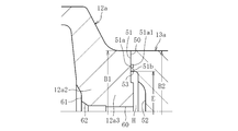
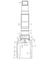
- FIG. 3 is an enlarged view of the vicinity of the joint between the cup member and the shaft member of the outer joint member of FIG. 2, and is a longitudinal sectional view showing a state before welding.
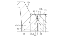
- FIG. 3 is an enlarged view of the vicinity of the joint between the cup member and the shaft member of the outer joint member of FIG. 2, and is a longitudinal sectional view showing a state after welding.
- FIG. 3 is an enlarged view of the vicinity of the joint between the cup member and the shaft member of the outer joint member of FIG. 2, and is a longitudinal sectional view showing a state after welding.
- FIGS. 4 to 11 show a method of manufacturing the outer joint member of the present embodiment.
- FIG. 1 is a diagram showing an overall structure of a drive shaft 1 in which the outer joint member 11 according to the first embodiment is used.
- the drive shaft 1 includes a sliding type constant velocity universal joint 10 disposed on the differential side (right side in the figure: hereinafter also referred to as inboard side) and a drive wheel side (left side in the figure: hereinafter also referred to as outboard side).
- the fixed type constant velocity universal joint 20 and the intermediate shaft 2 that couples the two constant velocity universal joints 10 and 20 so as to transmit torque are the main components.
- a sliding type constant velocity universal joint 10 shown in FIG. 1 is a so-called double offset type constant velocity universal joint (DOJ).
- the constant velocity universal joint 10 includes an outer joint member 11 having a cup portion 12 and a long shaft portion (hereinafter, also referred to as a long stem portion) 13 extending in the axial direction from the bottom portion of the cup portion 12, and an outer joint member 11.
- a cylindrical inner peripheral surface 42 of the member 11 and a spherical outer peripheral surface 43 of the inner joint member 16 are fitted with a spherical outer peripheral surface 45 and a spherical inner peripheral surface 46, respectively, and a cage 44 holding the ball 41.
- the center of curvature O 1 of the spherical outer peripheral surface 45 of the cage 44 and the center of curvature O 2 of the spherical inner peripheral surface 46 are offset from the joint center O by the same distance on the opposite side in the axial direction.
- the inner ring of the support bearing 6 is fixed to the outer peripheral surface of the long stem portion 13, and the outer ring of the support bearing 6 is fixed to the transmission case via a bracket (not shown).
- the outer joint member 11 is rotatably supported by the support bearing 6, and by providing such a support bearing 6, the outer joint member 11 is prevented from swinging during operation or the like as much as possible.
- a fixed type constant velocity universal joint 20 shown in FIG. 1 is a so-called Rzeppa type constant velocity universal joint, and has an outer side having a bottomed cylindrical cup portion 21a and a shaft portion 21b extending in the axial direction from the bottom portion of the cup portion 21a.
- a torque transmission element disposed between the joint member 21, the inner joint member 22 accommodated in the inner periphery of the cup portion 21 a of the outer joint member 21, and the cup portion 21 a and the inner joint member 22 of the outer joint member 21.
- a cage 24 that is disposed between the inner peripheral surface of the cup portion 21 a of the outer joint member 21 and the outer peripheral surface of the inner joint member 22 and holds the ball 23.
- An undercut-free type constant velocity universal joint may be used as the fixed type constant velocity universal joint 20.
- the intermediate shaft 2 has torque transmission splines (including serrations; the same applies hereinafter) 3 at the outer diameters at both ends. Then, the spline 3 on the inboard side is spline-fitted with the hole portion of the inner joint member 16 of the sliding type constant velocity universal joint 10, whereby the inner joint member 16 of the intermediate shaft 2 and the sliding type constant velocity universal joint 10. Are coupled so that torque can be transmitted. Further, the spline 3 on the outboard side is spline-fitted with the hole of the inner joint member 22 of the fixed type constant velocity universal joint 20, so that the intermediate shaft 2 and the inner joint member 22 of the fixed type constant velocity universal joint 20 are connected. Connected to transmit torque. As the intermediate shaft 2, a solid type is shown, but a hollow type can also be used.
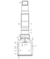
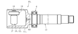
- FIG. 2 is an enlarged partial longitudinal sectional view of the outer joint member 11.
- the outer joint member 11 is open at one end, and has a bottom with a plurality of track grooves 30 and a cylindrical inner peripheral surface 42 on which balls 41 (see FIG. 1) roll at equal intervals in the circumferential direction of the inner peripheral surface.
- the outer joint member 11 is formed by welding a cup member 12a and a shaft member 13a.
- the cup member 12a is made of medium carbon steel containing 0.40 to 0.60% by weight of carbon such as S53C, and has a cylindrical portion 12a1 and a bottom portion in which a track groove 30 and a cylindrical inner peripheral surface 42 are formed on the inner periphery. 12a2 is an integrally molded product. A convex portion 12a3 is formed on the bottom portion 12a2 of the cup member 12a. A boot mounting groove 32 is formed on the outer periphery on the opening side of the cup member 12a, and a retaining ring groove 33 is formed on the inner periphery.
- the shaft member 13a has a bearing mounting surface 14 and a retaining ring groove 15 formed on the outer periphery on the cup member 12a side, and a spline Sp formed on the opposite end.
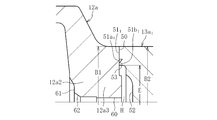
- the shaft member 13a is made of medium carbon steel containing 0.30 to 0.55 wt% carbon such as S40C. As shown in FIGS. 3a and 3b, the joining end surface 50 formed on the convex portion 12a3 of the bottom portion 12a2 of the cup member 12a and the joining end surface 51 of the end portion on the cup member 12a side of the shaft member 13a are abutted to each other. Welded by electron beam welding in the radial direction from the outside of 12a. The welded portion 49 is formed by a bead of a beam irradiated from the radially outer side of the cup member 12a.
- the outer diameters B1 and B2 of the joining end surface 50 and the joining end surface 51 are set to the same dimension for each joint size.
- the outer diameter B1 of the joining end surface 50 of the cup member 12a and the outer diameter B2 of the joining end surface 51 of the shaft member 13a are not necessarily the same size.
- the outer diameter B2 of the bonding end surface 51 is slightly smaller than the outer diameter B1 of the bonding end surface 50, and conversely, the outer diameter B2 of the bonding end surface 51 is slightly smaller than the outer diameter B1 of the bonding end surface 50.
- An appropriate dimensional difference such as a large diameter may be added.
- the outer diameters B1 and B2 of the joining end face 50 and the joining end face 51 are set to the same dimension for each joint size.
- the outer diameter B1 of the joining end face 50 and the joining end face 51 This is a concept including an appropriate dimensional difference with respect to the outer diameter B2.
- the welded portion 49 is formed on the joining end surface 51 closer to the cup member 12a than the bearing mounting surface 14 of the shaft member 13a, so that the bearing mounting surface 14 can be processed in advance and welded. Later post-processing can be abolished. Further, since burrs do not appear in the weld due to electron beam welding, post-processing of the weld can be omitted, and the manufacturing cost can be reduced. Further, 100% inspection by ultrasonic flaw detection of the welded portion is possible.
- FIGS. 3a and 3b the joining end face 50 of the cup member 12a is turned in a ring-shaped configuration, and the forging skin remains in the central portion in the radial direction. This shortens the turning time.
- a vent hole 60 is provided in the axial center of the cup member 12a so as to penetrate the bottom portion 12a2 of the cup member 12a.
- a counterbore 61 is provided on the bottom 12a2 of the cup member 12a, and a center hole 62 is formed in the counterbore 61.
- the center hole 62 is used for centering by fitting the center hole guide in the manufacturing process of the outer joint member 11 described later. Since the vent hole 60 is provided in the axial center of the cup member 12a, it is advantageous in terms of product strength. Further, since the center hole 62 is formed in the vent hole 60, it is advantageous in processing the center hole 62.
- a welding sputter receiving groove 51a is formed on the inner diameter side of the joining end surface 51 of the shaft member 13a, and an annular shielding part 51b is formed on the inner diameter side thereof.
- the weld sputter receiving groove 51 a is formed at the weld joint interface immediately below the bead of the weld 49.
- the hollow cavity H communicates with the outside air through the vent hole 60, when the sealed space at the time of welding is set to a medium vacuum level that establishes industrial production, a slight amount of remaining air enters the air at the time of welding.
- the weld 49 is pushed outward in the radial direction by heat, and the problem of insufficient weld length can be prevented.
- the medium vacuum means a vacuum of 100 Pa to 0.1 Pa defined by JIS 81126-1.
- the vent hole 60 Since the vent hole 60 is provided, the cup member 12a and the shaft member 13a are brought into contact with each other, and electron beam welding is performed in a medium vacuum (low pressure) atmosphere at a level that establishes industrial production of a constant velocity universal joint that is a mass-produced product.
- a medium vacuum (low pressure) atmosphere at a level that establishes industrial production of a constant velocity universal joint that is a mass-produced product.
- no dent is generated on the inner diameter side of the bead of the welded portion 49, and the inner diameter end portion of the bead of the weld 49 is sufficiently formed up to the weld sputter receiving groove 51a, so that the weld length can be secured.
- strength, quality, and reliability of a welding part can be improved.
- spatter during welding is captured by the weld sputter receiving groove 51a, and this spatter remains in the weld spatter receiving groove 51a due to the presence of the annular shielding portion 51b. For this reason, it is possible to prevent spatter from entering the cup portion 12a of the outer joint member 11, and it is possible to prevent the constant velocity universal joint 10 from being deteriorated and the NVH characteristics from being deteriorated.
- the annular shielding part 51b and the joining end face 51 are on the same plane, but a gap is set between the annular shielding part 51b and the joining end face 50 so that spatter does not flow out. Is called. It is desirable that the ratio of the gap between the annular shielding part 51b and the joining end surface 50 and the radial length of the annular shielding part 51b is 4 or more.
- the small spatter that has been confirmed by welding so far has a diameter of about 0.2 mm, and when the gap between the annular shield 51b and the joining end face 50 is 0.2 mm, it can theoretically pass through. The passage of spatter can be prevented by lengthening the length of the annular shielding portion 51b in accordance with the settable gap.
- the weld sputter receiving groove 51a has a width of about 1 to 3 mm and a depth of about 0.5 to 2 mm.
- the groove bottom corner 51a1 (see FIG. 3a) of the weld sputter receiving groove 51a is formed with an appropriate R in consideration of stress concentration.
- the welding spatter receiving groove 51a is also set to the same dimension for each joint size. For this reason, it is advantageous in terms of processing and variety integration.
- the welding spatter accommodation groove 13a can be easily formed when the shaft member 13a is turned.
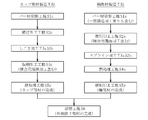
- FIG. 4 shows an outline of the manufacturing process of the outer joint member.
- the cup member 12a is manufactured by a manufacturing process including a bar material cutting process S1c, a forging process S2c, an ironing process S3c, and a turning process S4c, as shown.
- the shaft member 13a is manufactured by a manufacturing process including a bar material cutting process S1s, a turning process S2s, and a spline processing process S3s.
- the intermediate parts of the cup member 12a and the shaft member 13a manufactured in this way are each assigned a product number and managed.
- the outer joint member 11 is completed through the welding step S6, the heat treatment step S7, and the grinding step S8 of the cup member 12a and the shaft member 13a.
- Bar material cutting step S1c Based on the forging weight, the bar material is cut at a predetermined length to produce a billet.
- Forming process S2c The billet is forged, and the cylindrical part, the bottom part, and the convex part are integrally formed as a shape material of the cup member 12a.
- the manufacturing process of the shaft member 13a will be described.
- Bar material cutting process S1s Based on the total length of the shaft part, the bar material is cut at a predetermined length to produce a billet. Thereafter, depending on the shape of the shaft member 13a, the billet may be forged into an approximate shape by upset forging.
- Induction hardening and tempering are performed as heat treatment on at least the track grooves 30, the cylindrical inner peripheral surface 42 and the outer periphery of the shaft portion 13 of the cup portion 12 after welding. The weld is not heat treated.
- a hardened layer of about HRC 58 to 62 is formed on the track groove 30 and the cylindrical inner peripheral surface 42 of the cup portion 12. Further, a hardened layer of about HRC 50 to 62 is formed in a predetermined range on the outer periphery of the shaft portion 13.
- this manufacturing process incorporates a heat treatment process after the welding process, it is suitable for cup members and shaft members having shapes and specifications that affect the hardness of the heat treatment part because the temperature at the periphery increases due to the heat during welding. .
- FIG. 5A is a longitudinal sectional view showing a state after the ironing process of the cup member 12a
- FIG. 5B is a longitudinal sectional view showing a state after the turning process.
- the cylindrical portion 12a1', the bottom portion 12a2 'and the convex portion 12a3' are integrally formed in the forging step S2c.
- the track grooves 30 and the cylindrical cylindrical surface 42 are ironed, and the inner periphery of the cylindrical portion 12a1 'is finished as shown in FIG. 5a.
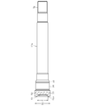
- FIG. 6 shows the state of the shaft member 13a in each processing step.
- 6a is a front view showing a billet 13a ′′ obtained by cutting a bar material
- FIG. 6b is a partial longitudinal sectional view showing a raw material 13a ′ obtained by forging the billet 13a ′′ into an approximate shape by upset forging
- FIG. It is a fragmentary longitudinal cross-section which shows the shaft member 13a after a turning process and a spline process.
- the billet 13a ′′ shown in FIG. 6a is manufactured. If necessary, as shown in FIG. 6b, the billet 13a ′′ is upset by forging and joining the shaft diameter within a predetermined range.
- a shaped member 13a ′ having a recess 52 formed on the side end (the end on the cup member 12a side) is manufactured.
- the outer diameter of the shaft member 13a, the bearing mounting surface 14, the retaining ring groove 15, the inner diameter surface 53 (inner diameter E) of the recess 52, the joining end surface 51, and the outside are turned, and the spline Sp is processed by rolling or pressing at the opposite end of the recess 52 in the spline processing step S3s.
- the outer diameter B1 of the joining end surface 50 of the cup member 12a shown in FIG. 5b is set to be the same size with one joint size.
- the shaft member 13a shown in FIG. 6c is for a long stem
- the outer diameter B2 of the joining end surface 51 is set to the same size with one joint size regardless of the shaft diameter or the outer peripheral shape.
- the joining end surface 51 of the shaft member 13 a is set at a position closer to the cup member 12 a than the bearing mounting surface 14. Since the dimensions are set in this way, the cup member 12a is shared, only the shaft member 13a is manufactured in various shaft diameters, lengths and outer peripheral shapes according to the vehicle type, and both the members 12a and 13a are welded.
- the outer joint member 11 suitable for various vehicle types can be manufactured. Details of sharing the cup member 12a will be described later.
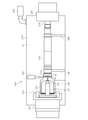
- FIGS. 7 and 8 are schematic views showing the welding apparatus.
- FIG. 7 shows a state before welding
- FIG. 8 shows a state where welding is performed.
- the welding apparatus 100 mainly includes an electron gun 101, a rotating device 102, a chuck 103, a center hole guide 104, a tail stock 105, a work cradle 106, a center hole guide 107, a case 108, and a vacuum pump 109.
- the configuration is mainly includes an electron gun 101, a rotating device 102, a chuck 103, a center hole guide 104, a tail stock 105, a work cradle 106, a center hole guide 107, a case 108, and a vacuum pump 109.
- the cup member 12a and the shaft member 13a which are workpieces, are placed on the workpiece cradle 106 in the welding apparatus 100.
- the chuck 103 and the center hole guide 107 at one end of the welding apparatus 100 are connected to the rotating device 102, and the cup member 12a is fitted by the chuck 103 with the center hole guide 107 fitted into the center hole 62 and the cup member 12a being centered.
- a center hole guide 104 is integrally attached to a tail stock 105 at the other end of the welding apparatus 100, and both are configured to be able to advance and retract in the axial direction (left and right direction in FIGS. 7 and 8).
- the center hole of the shaft member 13a is set in the center hole guide 104 and is centered.
- a vacuum pump 109 is connected to the case 108 of the welding apparatus 100.
- the sealed space means a space 111 formed by the case 108.
- the entire cup member 12 a and the shaft member 13 a are accommodated in the sealed space 111.
- An electron gun 101 is provided at a position corresponding to the joining end faces 50 and 51 of the cup member 12a and the shaft member 13a. The electron gun 101 is configured to be close to a predetermined position with respect to the workpiece.
- the cup member 12a and the shaft member 13a which are workpieces, are stocked at a place different from the welding apparatus 100.
- Each workpiece is taken out by, for example, a robot, conveyed into the case 108 of the welding apparatus 100 opened to the atmosphere shown in FIG. 7, and set at a predetermined position of the workpiece cradle 106.
- the center hole guide 104 and the tail stock 105 are retracted to the right in the drawing, and a gap is provided between the joining end surfaces 50 and 51 of the cup member 12a and the shaft member 13a.
- the door (not shown) of the case 108 is closed, and the vacuum pump 109 is activated to depressurize the sealed space 111 formed in the case 108.
- the recessed part 52 of the shaft member 13a, the internal diameter part 53, and the inside of the vent hole 60 are also decompressed.
- the center hole guide 104 and the tail stock 105 move forward to the left, and the gaps between the end surfaces 50 and 51 for joining the cup member 12a and the shaft member 13a are formed. Disappear.
- the cup member 12 a is centered by fitting the center hole guide 107 into the center hole 62 and fixed by the chuck 103, and the shaft member 13 a is supported by the center hole guide 104.
- the work cradle 106 moves away from the work. Since the distance between the workpiece cradle 106 and the workpiece at this time may be very small, the above-described interval is not shown in FIG. Of course, it is possible to have a structure in which the workpiece cradle 106 is largely retracted downward.
- the electron gun 101 approaches the work to a predetermined position, rotates the work, and starts preheating.
- the preheating condition is set to a temperature lower than the welding temperature by, for example, irradiating the electron gun 101 close to the workpiece and irradiating the electron beam with a large spot diameter. By preheating, burning cracks can be prevented by slowing the cooling rate after welding.
- the electron gun 101 is retracted to a predetermined position, and an electron beam is irradiated in the radial direction from the outside of the workpiece to start welding.
- the shaft member 13a has a weld sputter receiving groove 51a formed in the weld joint interface immediately below the bead of the welded portion 49 on the inner diameter side of the joining end face 51.
- An annular shield 51b is formed.
- a gap is set between the annular shielding portion 51b and the joining end face 50 so that the spatter does not flow out, and ventilation is performed through the gap.
- the hollow cavity H formed between the cup member 12 a and the shaft member 13 a communicates with the outside air through the vent hole 60.
- the center hole guide 107 is fitted into the center hole 62 provided in the vent hole 60, but air flows back and forth through the contact portion by the fitting.
- the hollow cavity H communicates with the outside air through the vent hole 60, when the medium vacuum is set to a level that establishes industrial production at the time of welding, a slight amount of air remains as heat input at the time of welding.
- the welded portion 49 is not pushed outward in the radial direction, and the weld length can be secured.
- spatter during welding is captured by the weld sputter receiving groove 51a, and this spatter remains in the weld spatter receiving groove 51a due to the presence of the annular shielding portion 51b.
- the sealed space 111 is opened to the atmosphere. Then, with the workpiece cradle 106 raised and supporting the workpiece, the center hole guide 104 and the tail stock 105 are retracted to the right, and the chuck 103 is released. Thereafter, for example, the robot grabs the workpiece, removes it from the welding apparatus 100, and aligns it with the cooling stocker.
- the configuration of the sealed space 111 in the case 108 can be simplified.
- the above-described welding apparatus 100 uses the cup member 12a.
- the pressure in the sealed space 111 was set to 6.7 Pa or less for welding.
- Electron beam welding was performed.
- a welded portion 49 having a raised height (0.5 mm or less) on the weld surface that does not affect the incorporation of the bearing 6 into the shaft portion of the outer joint member 11 was obtained. Further, by the soaking by preheating, the weld zone hardness after completion of welding could be suppressed within the range of Hv 200 to 500, and the welding strength was high and stable welding condition and quality could be obtained. Furthermore, by welding the sealed space 111 of the welding apparatus 100 at atmospheric pressure or lower, it is possible to suppress a pressure change in the hollow cavity during welding, and to prevent the melt from being blown up or drawn into the inner diameter side. did it.
- the setting of the pressure 6.7 Pa or less in the sealed space 111 in the case 108 is a vacuum (low pressure) condition at a level that establishes industrial production of a constant velocity universal joint that is a mass-produced product for automobiles and the like.
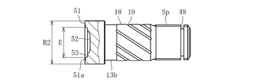
- the shaft member 13b shown in FIGS. 9 and 10 is for a standard stem on the inboard side.
- the shaft member 13b is formed with a joining end surface 51 that abuts the joining end surface 50 (see FIG. 5b) of the bottom 12a2 (projection 12a3) of the cup member 12a.
- the outer diameter B2 and the inner diameter E of the joining end face 51 are formed to have the same dimensions as the outer diameter B1 and the inner diameter E of the joining end face 51 of the long stem type shaft member 13a shown in FIG. 6c.
- this shaft member 13b is for a standard stem on the inboard side, the length of the shaft portion is short, and a sliding bearing surface 18 is formed in the central portion in the axial direction, and a plurality of oil grooves 19 are formed on this sliding bearing surface 18. Is formed.
- a spline Sp and a retaining ring groove 48 are formed at the end opposite to the cup member 12a side.
- the outer diameter B2 of the joining end surface 51 of the shaft members 13a and 13b is different even if the stem length or the long stem of the standard length is different or the various shaft diameters and outer peripheral shapes are different for each vehicle type. The same dimensions are set.
- the welding sputter accommodation groove 51a of the shaft members 13a and 13b is also set to the same dimension for each joint size.
- the cup member and the vehicle type that are shared for each joint size are used.
- a shaft member having various shaft specifications can be prepared in a state before heat treatment, and can be managed by assigning a product number to each of the intermediate parts of the cup member 12a and the shaft members 13a and 13b. And even if the cup member 12a is integrated, various outer joint members 11 according to requirements can be quickly manufactured in combination with shaft members 13a and 13b having various shaft specifications for each vehicle type. . Therefore, it is possible to reduce the cost and production management load by integrating the types of cup members 12a.
- cup members In the above, for the sake of easy understanding, the type integration of cup members has been explained by taking the difference between the standard length stem and the long stem as an example, but the standard length is not limited to this. This also applies to the integration of cup members with respect to shaft members having various shaft specifications for each vehicle type between the stems and shaft members having various shaft specifications for each vehicle type between the long stems.
- FIG. 11 shows an example of product type integration of cup members of this embodiment.
- the cup member is shared by one joint size, and is managed with, for example, a product number C001.
- the shaft member has various shaft part specifications for each vehicle type, and is managed by being assigned product numbers S001, S002, to S (n), for example.
- product numbers S001, S002, to S (n) for example.
- the integration of the cup member types can reduce the cost and the production management load.
- the cup member is not limited to one type with one joint size, that is, one model number. For example, a plurality of types (multiple types with one joint size according to specifications with different maximum operating angles). Model number) cup members are set, and those having the same outer diameter B1 of the joining end faces of these cup members are wrapped.
- FIG. 12A is a longitudinal sectional view showing a state before welding
- FIG. 12B is a longitudinal sectional view showing a state after welding.
- Welding spatter receiving grooves 51a 1 of the present modification is directed to copying shape groove face of the inner diameter side is formed to be inclined. Therefore, it is possible to process and connecting the end faces 51 1 to weld spatter receiving groove 51a 1 by turning copying during turning of the joining end surface 51 1 of the shaft member 13a 1 in one step, weld spatter accommodated by parting bytes groove possible to shorten the turning step is omitted additional turning steps 51a 1.
- FIG. 13a is a longitudinal sectional view showing a state before welding
- FIG. 13b is a longitudinal sectional view showing a state after welding.
- Welding spatter receiving groove 50a 1 of the present modification forms the joining end face 50 1 of the cup member 12a 1, weld spatter accommodating grooves 50a 1 inner diameter side to the inner diameter surface (inner diameter E) the points forming the first Different from the outer joint member of the embodiment. Since other configurations are the same as those of the outer joint member 11 of the first embodiment, parts having the same functions are denoted by the same reference numerals (excluding subscripts), and the parts of the first embodiment. All the above-described contents of the outer joint member and the manufacturing method thereof apply mutatis mutandis, and the description thereof is omitted.
- FIG. 14 shows a modification of the method for manufacturing the outer joint member.
- the heat treatment process of the cup member in the heat treatment process S7 of FIG. 4 described above is incorporated before the welding process S6 to form a heat treatment process S5c, and the cup member is prepared as a finished product.
- Contents excluding this point that is, the outline of each process described above in the outer joint member of the first embodiment, the state in the main processing steps of the cup member and the shaft member, common use of the cup member, welding method, product type integration Since the structure of the outer joint member and the like are the same, all the contents of the first embodiment are applied mutatis mutandis to the present modification, and only different portions will be described.
- the cup member 12a has a shape extending from the joining end face 50 to the cylindrical portion 12a1 having a large diameter through the bottom portion 12a2, and the portion subjected to heat treatment as quenching and tempering is the cylindrical portion 12a1.
- the cup member 12a can be manufactured independently up to a finished product that has undergone forging, turning, and heat treatment, and productivity is improved including reduction of setup.
- the part number of the cup member in the drawing is only the part number as the finished product. Since the shaft member and the outer joint member are the same as those in the first embodiment, description thereof will be omitted.
- FIG. 15 shows another modification of the method for manufacturing the outer joint member.
- the heat treatment process S5c of the cup member is incorporated by incorporating the heat treatment process of the cup part and the shaft part and the grinding process S8 of the shaft part of the heat treatment process S7 of FIG. 4 before the welding process S6.
- the shaft member heat treatment step S4s and the grinding step S5s are performed. Therefore, both the cup member and the shaft member are prepared as finished products.
- the shaft member is formed with a hardened layer of about HRC 50 to 62 by induction hardening in a predetermined range of the outer peripheral surface in the heat treatment step S4s after the spline processing step S3s.
- the predetermined axial direction portion including the joining end face 51 is not subjected to heat treatment.
- duplication description is abbreviate
- the shaft member is moved to the grinding step S5s to finish the bearing mounting surface 14 and the like. Thereby, the shaft member as a finished product is obtained. Then, a product number as a finished product is assigned to the shaft member and managed.
- the manufacturing process of this modification is suitable for the case of a cup member and a shaft member having a shape and specifications that do not cause a thermal effect during welding on the heat treatment part.
- both the cup member and the shaft member can be managed by assigning product numbers as finished products. Therefore, the cost reduction and the production management load reduction due to the integration of the types of cup members become more remarkable. Further, the cup member and the shaft member can be separately manufactured up to a finished product that has undergone forging, turning, heat treatment, grinding after heat treatment, and the like, and the productivity is further improved, including reduction of setup.
- the product numbers of the cup member and the shaft member in the drawing are the product numbers of the finished products. . Since the outer joint member is the same as that of the first embodiment, the description thereof is omitted.
- the cup member and the shaft member as a finished part are not limited to those subjected to the finishing process such as the grinding process after the heat treatment and the post-quenching cutting process described above, and the heat-treated cup with the finishing process remaining. It includes members and shaft members.
- the cup member is not limited to one type of joint size, that is, one model number. That is, as described above, for example, a plurality of types (plural model numbers) of cup members are set with a single joint size according to different specifications of the maximum operating angle, and the outer diameters B1 of the joining end surfaces of these cup members are the same. Wrapping what is dimensioned. In addition to this, in order to manage the cup member in multiple forms of intermediate parts and finished parts before heat treatment in consideration of, for example, joint functions, actual conditions at the manufacturing site, productivity, etc. These types (multiple model numbers) of cup members are set, and those having the same outer diameter B1 of the joining end faces of these cup members are also included.
- Sliding type constant velocity universal joint 10 2 shown in FIG. 16 is a tripod type constant velocity universal joint (TJ), and a long stem portion 13 extending axially from the bottom of the cup portion 12 2 and the cup portion 12 2 an outer joint member 11 2 having an outer joint member 11 2 of the cup portion 12 the inner joint member 16 2 accommodated in the inner circumference of the 2, disposed between the outer joint member 11 2 and the inner joint member 16 2 And a roller 19 as a torque transmission element.
- the inner joint member 16 2 is composed of a tripod member 17 three trunnions 18 which the roller 19 externally fitted is provided at equal circumferential intervals.
- An inner ring of the support bearing 6 is fixed to the outer peripheral surface of the long stem portion 13, and the outer ring of the support bearing 6 is fixed to the transmission case via a bracket (not shown).
- the outer joint member 11 2 is rotatably supported by the support bearing 6, deflection of the outer joint member 11 2 at the operating time or the like is prevented as much as possible.
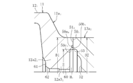
- Figure 17 shows a partial longitudinal section of the outer joint member 11 2.
- the outer joint member 11 2 has one end open, the inner roller 19 in the circumferential direction trisected position in the circumferential surface (see FIG. 16) to roll the track grooves 30 2 and the inner circumferential surface 31 2 spline Sp of but a bottomed cylindrical cup portion 12 2 formed, extending axially from the bottom of the cup portion 12 2, as the torque transmitting connection portion to the outer circumference of the end portion of the opposite side of the cup portion 12 2 side And a long stem portion 13 provided with.
- the outer joint member 11 2, the cup member 12a 2 and the shaft member 13a is formed by welding.
- the cup member 12a 2 is a single piece consisting of an inner cylindrical portion inner peripheral surface 31 2 and the track grooves 30 2 are formed on the peripheral 12a1 2 and the bottom 12a2 2.
- the bottom 12a2 2 of the cup member 12a 2 projecting portion 12a3 2 is formed.
- a boot mounting groove 32 is formed on the outer periphery of the cup member 12a 2 on the opening side.
- the shaft member 13a is a bearing mounting surface 14 and retaining ring groove 15 on the outer periphery of the cup member 12a 2 side is formed a spline Sp is formed at the opposite end from the cup member 12a 2 side.
- Weld 49 is formed at the bead emitted from the radially outer side of the cup member 12a 2.
- provided weld spatter housing groove 51a on the inner diameter side of the joint end face 51 of the shaft member 13a is in the hollow cavity H at the bottom 12a2 2 the axis of the cup member 12a2
- a vent hole 60 is provided.
- the outer diameter of the joining end face 50 2 and connecting end face 51 is set to the same size for each joint size.
- Weld 49 because it is formed in the bearing mounting surface 14 cup member 12a 2 side of the joint end face 51 than the shaft member 13a, etc. bearing mount surface 14 can be eliminated post-processing after the pre-processable welding. Further, since burrs do not appear in the weld due to electron beam welding, post-processing of the weld can be omitted, and the manufacturing cost can be reduced.
- the outer joint member 11 2 is the same as the contents described above in the outer joint member 11 according to the first embodiment described above, the steps described above in the outer joint member of the first embodiment Since the outline, the state in the main processing steps of the cup member and the shaft member, the common use of the cup member, the welding method, the product type integration, the configuration of the outer joint member, etc. are the same, all the contents of the first embodiment are described here. The same applies to the embodiment, and the description is omitted.
- the electron beam welding is applied.
- laser welding can be similarly applied.
- the present invention can also be applied to an outer joint member of another sliding type constant velocity universal joint such as a type constant velocity universal joint, and further to an outer joint member of a fixed type constant velocity universal joint.
- the present invention is applied to the outer joint member of the constant velocity universal joint constituting the drive shaft.
- the present invention is also applied to the outer joint member of the constant velocity universal joint constituting the propeller shaft. Can do.
Landscapes
- Engineering & Computer Science (AREA)
- Mechanical Engineering (AREA)
- General Engineering & Computer Science (AREA)
- Physics & Mathematics (AREA)
- Optics & Photonics (AREA)
- Plasma & Fusion (AREA)
- Welding Or Cutting Using Electron Beams (AREA)
- Laser Beam Processing (AREA)
- Shafts, Cranks, Connecting Bars, And Related Bearings (AREA)
Abstract
トルク伝達要素19、23が係合するトラック溝30を内周に形成したカップ部12、121、122と、このカップ部12、121、122の底部に形成された軸部13とを別部材で構成し、カップ部12、121、122を形成するカップ部材12a、12a2、12a2と軸部13を形成する軸部材13a、13a2とを突き合わせて溶接してなる等速自在継手10の外側継手部材11、112であって、カップ部材12a、12a2、12a2の接合用端面50、501、502と軸部材13a、13a2の接合用端面51、511を突き合わせることにより中空空洞部Hが形成される等速自在継手10の外側継手部材11において、カップ部材12a、12a2、12a2の軸心に中空空洞部H、H1に通じる通気孔60を設けると共に、カップ部材12a、12a2、12a2の接合用端面50、501、502と軸部材13a、13a2の接合用端面51、511のいずれか一方の内径側に溶接スパッタ収容溝50a1、51a、51a1を形成したことを特徴とする。
Description
この発明は、等速自在継手の外側継手部材に関する。
自動車や各種産業機械の動力伝達系を構成する等速自在継手は、駆動側と従動側の二軸をトルク伝達可能に連結すると共に、前記二軸が作動角をとっても等速で回転トルクを伝達することができる。等速自在継手は、角度変位のみを許容する固定式等速自在継手と、角度変位および軸方向変位の両方を許容する摺動式等速自在継手とに大別され、例えば、自動車のエンジンから駆動車輪に動力を伝達するドライブシャフトにおいては、デフ側(インボード側)に摺動式等速自在継手が使用され、駆動車輪側(アウトボード側)には固定式等速自在継手が使用される。
摺動式又は固定式を問わず、等速自在継手は主要な構成部材として、内周面にトルク伝達要素が係合するトラック溝を形成したカップ部と、このカップ部の底部から軸方向に延びた軸部とを有する外側継手部材を備えている。この外側継手部材は、中実の棒状素材(バー材)を鍛造加工やしごき加工等の塑性加工、切削加工、熱処理、研削加工等を施すことによって、カップ部と軸部とを一体成形する場合が多い。
ところで、外側継手部材として、長寸の軸部(ロングステム)を有するものを用いる場合がある。左右のドライブシャフトの長さを等しくするために、片側のドライブシャフトのインボード側外側継手部材をロングステムにし、このロングステムが転がり軸受によって回転支持される。ロングステム部の長さは、車種により異なるが、概ね250~400mm程度である。この外側継手部材では、軸部が長寸であるために、カップ部と軸部を安価に精度良く一体成形することが困難である。そのため、カップ部と軸部を別部材で構成し、電子ビーム溶接を施したものが提案されている(特許文献1)。
また、カップ部を形成するカップ部材と軸部を形成する軸部材とを溶接するタイプの外側継手部材において、両部材の接合部に形成される中空空洞部の内圧変化を抑えるために中空空洞部に通じる通気孔を設けたものが提案されている(特許文献2)。
特許文献1に記載された外側継手部材の製造方法は、カップ部材の接合用端面と軸部材の接合用端面を突合せて、この突合せ部に外側から半径方向にビームを照射して溶接するもので、接合用端面の外径をジョイントサイズ毎に同一寸法にしたものである。この構成により、溶接部の強度、品質の向上、溶接コストの削減と共に、カップ部材および軸部材の生産性の向上、並びにカップ部材の品種統合によるコスト低減、生産管理の軽減が可能な優れた外側継手部材の製造方法が提案されている。しかし、溶接時の密閉空間が工業生産を成立させるレベルの中真空とした場合に、僅かに残存する空気が、溶接時の入熱により溶接部を半径方向外側に向かって押し出し、溶接長さが不足する問題が判明した。この問題に対して特許文献1は着目するに至っていない。
特許文献2に記載された外側継手部材は、中空空洞部に通じる通気孔を設けているが、溶接を真空環境で行うことを意図したものではない。加えて、溶接時のスパッタが通気孔を通じてカップ部内部に侵入することへの問題に着目するに至っていない。
外側継手部材のカップ部内には、トルク伝達のためのトラック溝や保持器との嵌合面が形成されており、本発明は、溶接時のスパッタがカップ部内に侵入すると、トルク伝達時の異物となり、耐久性やNVH(Noise,Vibration,Harshness、以下同じ)特性に悪影響を及ぼす可能性があることに着目したものである。
本発明は、前述の問題点に鑑みて提案されたもので、その目的とするところは、等速自在継手の外側継手部材の溶接長さを確保すると共に溶接時に発生したスパッタが外側継手部材のカップ部内に侵入することを防止し、等速自在継手の耐久性やNVH特性の低下を防止した外側継手部材を提供することにある。
前述の目的を達成するための技術的手段として、本発明は、トルク伝達要素が係合するトラック溝を内周に形成したカップ部と、このカップ部の底部に形成された軸部とを別部材で構成し、前記カップ部を形成するカップ部材と前記軸部を形成する軸部材とを突き合わせて溶接してなる等速自在継手の外側継手部材であって、前記カップ部材の接合用端面と前記軸部材の接合用端面を突き合わせることにより中空空洞部が形成される等速自在継手の外側継手部材において、前記カップ部材の軸心に前記中空空洞部に通じる通気孔を設けると共に、前記カップ部材の接合用端面と前記軸部材の接合用端面のいずれか一方の内径側に溶接スパッタ収容溝を形成したことを特徴とする。
上記の構成により、外側継手部材の溶接長さを確保すると共に溶接時に発生したスパッタが外側継手部材のカップ部内に侵入することを防止し、等速自在継手の耐久性やNVH特性の低下を防止することができる。
上記の通気孔にセンター穴を形成したことにより、センター穴の加工面で有利である。
上記の溶接スパッタ収容溝をジョイントサイズ毎に同一寸法に設定したことにより、加工や品種統合の面で有利である。
本発明に係る等速自在継手の外側継手部材によれば、外側継手部材の溶接長さを確保すると共に溶接時に発生したスパッタが外側継手部材のカップ部内に侵入することを防止し、等速自在継手の耐久性やNVH特性の低下を防止することができる。
以下に本発明の実施の形態を図面に基づいて説明する。
本発明に係る等速自在継手の外側継手部材の第1の実施形態を図1~3に示し、本実施形態の外側継手部材を製造する方法を図4~11に示す。
図1は、第1の実施形態に係る外側継手部材11が使用されたドライブシャフト1の全体構造を示す図である。ドライブシャフト1は、デフ側(図中右側:以下、インボード側ともいう)に配置される摺動式等速自在継手10と、駆動車輪側(図中左側:以下、アウトボード側ともいう)に配置される固定式等速自在継手20と、両等速自在継手10、20をトルク伝達可能に連結する中間シャフト2とを主要な構成とする。
図1に示す摺動式等速自在継手10は、いわゆるダブルオフセット型等速自在継手(DOJ)である。この等速自在継手10は、カップ部12とカップ部12の底部から軸方向に延びた長寸軸部(以下、ロングステム部ともいう)13とを有する外側継手部材11と、外側継手部材11のカップ部12の内周に収容された内側継手部材16と、外側継手部材11と内側継手部材16のトラック溝30、40との間に配置されたトルク伝達要素としてのボール41と、外側継手部材11の筒状内周面42と内側継手部材16の球状外周面43とに、それぞれ嵌合する球状外周面45、球状内周面46を有し、ボール41を保持する保持器44とを備える。保持器44の球状外周面45の曲率中心O1と球状内周面46の曲率中心O2は、継手中心Oに対して、軸方向に反対側に等距離オフセットされている。
ロングステム部13の外周面にはサポートベアリング6の内輪が固定されており、このサポートベアリング6の外輪は、図示しないブラケットを介してトランスミッションケースに固定されている。外側継手部材11は、サポートベアリング6によって回転自在に支持され、このようなサポートベアリング6を設けておくことにより、運転時等における外側継手部材11の振れが可及的に防止される。
図1に示す固定式等速自在継手20は、いわゆるツェッパ型等速自在継手であり、有底筒状のカップ部21aとカップ部21aの底部から軸方向に延びた軸部21bとを有する外側継手部材21と、外側継手部材21のカップ部21aの内周に収容された内側継手部材22と、外側継手部材21のカップ部21aと内側継手部材22との間に配置されたトルク伝達要素としてのボール23と、外側継手部材21のカップ部21aの内周面と内側継手部材22の外周面との間に配され、ボール23を保持する保持器24とを備える。なお、固定式等速自在継手20として、アンダーカットフリー型等速自在継手が用いられる場合もある。
中間シャフト2は、その両端部外径にトルク伝達用のスプライン(セレーションを含む。以下、同じ)3を有する。そして、インボード側のスプライン3を摺動式等速自在継手10の内側継手部材16の孔部とスプライン嵌合させることにより、中間シャフト2と摺動式等速自在継手10の内側継手部材16とがトルク伝達可能に連結される。また、アウトボード側のスプライン3を固定式等速自在継手20の内側継手部材22の孔部とスプライン嵌合させることにより、中間シャフト2と固定式等速自在継手20の内側継手部材22とがトルク伝達可能に連結される。この中間シャフト2として、中実タイプを示したが、中空タイプを用いることもできる。
両等速自在継手10、20の内部には潤滑剤としてのグリースが封入されている。グリースの外部漏洩や継手外部からの異物侵入を防止するため、摺動式等速自在継手10の外側継手部材11と中間シャフト2との間、および固定式等速自在継手20の外側継手部材21と中間シャフト2との間には、蛇腹状のブーツ4、5がそれぞれ装着されている。
図2に基づき、本実施形態の外側継手部材を説明する。図2は、外側継手部材11を拡大した部分縦断面図である。外側継手部材11は、一端が開口し、内周面の円周方向等間隔にボール41(図1参照)が転動する複数のトラック溝30と筒状内周面42が形成された有底筒状のカップ部12と、カップ部12の底部から軸方向に延び、カップ部12とは反対側の端部外周にトルク伝達用連結部としてのスプラインSpが設けられたロングステム部13とからなる。外側継手部材11は、カップ部材12a、軸部材13aが溶接されて形成されている。
カップ部材12aは、S53C等の0.40~0.60重量%の炭素を含む中炭素鋼からなり、内周にトラック溝30と筒状内周面42が形成された筒状部12a1と底部12a2からなる一体成形品である。カップ部材12aの底部12a2には凸部12a3が形成されている。カップ部材12aの開口側の外周にはブーツ取付溝32が形成され、内周には止め輪溝33が形成されている。軸部材13aは、カップ部材12a側の外周に軸受装着面14および止め輪溝15が形成され、反対側の端部にスプラインSpが形成されている。
軸部材13aは、S40C等の0.30~0.55重量%の炭素を含む中炭素鋼からなる。図3aおよび図3bに示すように、カップ部材12aの底部12a2の凸部12a3に形成された接合用端面50と軸部材13aのカップ部材12a側端部の接合用端面51とを突合せ、カップ部材12aの外側から半径方向に電子ビーム溶接により溶接されている。溶接部49は、カップ部材12aの半径方向外側から照射されたビームによるビードで形成されている。詳細は後述するが、接合用端面50と接合用端面51の外径B1、B2は、ジョイントサイズ毎に同一寸法に設定されている。ただし、カップ部材12aの接合用端面50の外径B1と軸部材13aの接合用端面51の外径B2を、必ずしも同一寸法にする必要はなく、例えば、溶接ビードの状態などを考慮して、接合用端面50の外径B1に対して接合用端面51の外径B2を若干小径にすることや、反対に接合用端面50の外径B1に対して接合用端面51の外径B2を若干大径にするなど適宜の寸法差をつけてもよい。本明細書において、接合用端面50と接合用端面51の外径B1、B2は、ジョイントサイズ毎に同一寸法に設定されているとは、接合用端面50の外径B1と接合用端面51の外径B2との間においては適宜の寸法差があることも含む概念のものである。
図2および図3aに示すように、溶接部49が、軸部材13aの軸受装着面14よりカップ部材12a側の接合用端面51に形成されるので、軸受装着面14などは前もって加工可能で溶接後の後加工を廃止できる。また、電子ビーム溶接のため溶接部にバリが出ないので、溶接部の後加工も省略でき、製造コストが削減できる。さらに、溶接部の超音波探傷による全数検査が可能である。
本実施形態の外側継手部材11の特徴を図3aおよび図3bに基づいて説明する。図3aに示すように、カップ部材12aの接合用端面50は、環状に座ぐった形態で旋削加工し、半径方向の中央部は鍛造肌を残している。これにより、旋削加工時間を短縮している。カップ部材12aの軸心には、カップ部材12aの底部12a2を貫通して通気孔60が設けられている。カップ部材12aの底部12a2に座ぐり部61が設けられ、この座ぐり部61にセンター穴62が形成されている。センター穴62は、後述する外側継手部材11の製造工程において、センター穴ガイドを嵌合させて心出しするために用いる。通気孔60をカップ部材12aの軸心に設けたので、製品強度面で有利である。また、通気孔60にセンター穴62を形成したので、センター穴62の加工面で有利である。
軸部材13aの接合用端面51の内径側に溶接スパッタ収容溝51aが形成され、さらにその内径側に環状遮蔽部51bが形成されている。図3bに示すように、溶接スパッタ収容溝51aは溶接部49のビードの直下の溶接接合界面に形成されている。両接合用端面50、51を突き合わせると、中空空洞部Hが形成されるが、中空空洞部Hに通気孔60の一端が開口しているので、外気と連通する。
中空空洞部Hが通気孔60を介して外気と連通しているので、溶接時の密閉空間を工業生産を成立させるレベルの中真空とした場合に、僅かに残存する空気が、溶接時の入熱により溶接部49を半径方向外側に向かって押し出し、溶接長さが不足する問題を防止できる。ここで、中真空とは、JIS 8126-1で規定された100Pa~0.1Paの真空を意味する。
通気孔60が設けれているので、カップ部材12aと軸部材13aを突き合わせて、量産製品である等速自在継手の工業生産を成立させるレベルの中真空(低圧)雰囲気内で電子ビーム溶接を行った場合、溶接部49のビードの内径側には凹みが発生せず、溶接49のビードの内径端部が溶接スパッタ収容溝51aまで十分形成され、溶接長さを確保できる。これにより、溶接部の強度、品質、信頼性を向上させることができる。
また、溶接時のスパッタは、溶接スパッタ収容溝51aで捕捉され、このスパッタは、環状遮蔽部51bの存在により溶接スパッタ収容溝51a内に留まる。このため、スパッタが外側継手部材11のカップ部12a内に侵入することを防止し、等速自在継手10の耐久性やNVH特性の低下を防止することができる。
環状遮蔽部51bと接合用端面51は、同一平面とするが、環状遮蔽部51bと接合用端面50との間は、スパッタが流出しない程度の隙間に設定され、この隙間を介して通気が行われる。環状遮蔽部51bと接合用端面50の隙間と環状遮蔽部51bの半径方向の長さの比が4以上であることが望ましい。これまでの溶接で確認できているスパッタの小さいものは直径0.2mm程度であり、環状遮蔽部51bと接合用端面50の隙間が0.2mmとなった場合は、理論上すり抜け可能であるが、環状遮蔽部51bの半径方向の長さを設定可能な隙間に合わせて長くすることで、スパッタの通過を防止できる。
溶接スパッタ収容溝51aは、幅が1~3mm程度で、深さが0.5~2mm程度である。溶接スパッタ収容溝51aの溝底角部51a1(図3a参照)は、応力集中を考慮して適宜のRで形成している。溶接スパッタ収容溝51aもジョイントサイズ毎に同一寸法に設定している。このため、加工や品種統合の面で有利である。
溶接スパッタ収容溝51aを軸部材13aに設けることにより、軸部材13aの旋削加工時に溶接スパッタ収容溝13aを容易に形成することができる。
次に、本実施形態の外側継手部材を製造する方法を図4~11に基づいて説明する。図4は、外側継手部材の製造工程の概要を示す。本実施形態では、カップ部材12aは、図示のように、バー材切断工程S1c、鍛造加工工程S2c、しごき加工工程S3cおよび旋削加工工程S4cからなる製造工程により製造される。一方、軸部材13aは、バー材切断工程S1s、旋削加工工程S2sおよびスプライン加工工程S3sからなる製造工程により製造される。このようにして製造されたカップ部材12aと軸部材13aの中間部品は、それぞれ、品番が付与されて管理される。
その後、カップ部材12aと軸部材13aとが溶接工程S6、熱処理工程S7および研削加工工程S8を経て外側継手部材11が完成する。
各工程の概要を説明する。各工程は、代表的な例を示すものであって、必要に応じて適宜変更や追加を行うことができる。まず、カップ部材12aの製造工程を説明する。
[バー材切断工程S1c]
鍛造重量に基づいてバー材を所定長さで切断し、ビレットを製作する。
鍛造重量に基づいてバー材を所定長さで切断し、ビレットを製作する。
[鍛造加工工程S2c]
ビレットを鍛造加工により、カップ部材12aの素形材として筒状部、底部および凸部を一体成形する。
ビレットを鍛造加工により、カップ部材12aの素形材として筒状部、底部および凸部を一体成形する。
[しごき加工工程S3c]
前記素形材のトラック溝30および筒状円筒面42をしごき加工して、カップ部材12aの筒状部の内周を仕上げる。
前記素形材のトラック溝30および筒状円筒面42をしごき加工して、カップ部材12aの筒状部の内周を仕上げる。
[旋削加工工程S4c]
しごき加工後の素形材に、外周面、ブーツ取付溝32、止め輪溝33、接合用端面50、通気孔60等を旋削加工する。本実施形態では、旋削加工工程S4cの後、中間部品としてのカップ部材12aに品番を付与して管理する。
しごき加工後の素形材に、外周面、ブーツ取付溝32、止め輪溝33、接合用端面50、通気孔60等を旋削加工する。本実施形態では、旋削加工工程S4cの後、中間部品としてのカップ部材12aに品番を付与して管理する。
次に、軸部材13aの製造工程を説明する。
[バー材切断工程S1s]
軸部全長に基づいてバー材を所定長さで切断し、ビレットを製作する。その後、軸部材13aの形状に応じて、ビレットをアプセット鍛造により概略形状に鍛造加工する場合もある。
[バー材切断工程S1s]
軸部全長に基づいてバー材を所定長さで切断し、ビレットを製作する。その後、軸部材13aの形状に応じて、ビレットをアプセット鍛造により概略形状に鍛造加工する場合もある。
[旋削加工工程S2s]
ビレット又は素形材の外周面(軸受装着面14、止め輪溝15、スプライン下径、端面など)とカップ部材12a側端部の接合用端面51や溶接スパッタ収容溝51aを旋削加工する。
ビレット又は素形材の外周面(軸受装着面14、止め輪溝15、スプライン下径、端面など)とカップ部材12a側端部の接合用端面51や溶接スパッタ収容溝51aを旋削加工する。
[スプライン加工工程S3s]
旋削加工後の軸部材にスプラインを転造加工する。ただし、スプラインの加工は転造加工に限られるものではなく、適宜プレス加工等に置き換えることもできる。本実施形態では、スプライン加工後、中間部品としての軸部材13aに品番を付与して管理する。
旋削加工後の軸部材にスプラインを転造加工する。ただし、スプラインの加工は転造加工に限られるものではなく、適宜プレス加工等に置き換えることもできる。本実施形態では、スプライン加工後、中間部品としての軸部材13aに品番を付与して管理する。
次に、カップ部材12aと軸部材13aから外側継手部材11が完成するまでの製造工程を説明する。
[溶接工程S6]
カップ部材12aの接合用端面50と軸部材13aの接合用端面51を突合せて溶接する。
カップ部材12aの接合用端面50と軸部材13aの接合用端面51を突合せて溶接する。
[熱処理工程S7]
溶接後のカップ部12の少なくともトラック溝30、筒状内周面42および軸部13の外周の必要範囲に熱処理として高周波焼入れ焼戻しを行う。溶接部は熱処理を施さない。カップ部12のトラック溝30や筒状内周面42はHRC58~62程度の硬化層が形成される。また、軸部13の外周の所定範囲にHRC50~62程度の硬化層が形成される。
溶接後のカップ部12の少なくともトラック溝30、筒状内周面42および軸部13の外周の必要範囲に熱処理として高周波焼入れ焼戻しを行う。溶接部は熱処理を施さない。カップ部12のトラック溝30や筒状内周面42はHRC58~62程度の硬化層が形成される。また、軸部13の外周の所定範囲にHRC50~62程度の硬化層が形成される。
[研削加工工程S8]
熱処理後、軸部13の軸受装着面14等を研削加工して仕上げる。これにより、外側継手部材11が完成する。
熱処理後、軸部13の軸受装着面14等を研削加工して仕上げる。これにより、外側継手部材11が完成する。
この製造工程では、溶接工程後に熱処理工程を組み入れたものであるので、溶接時の熱で周辺部の温度が上昇し、熱処理部の硬度に影響がある形状や仕様のカップ部材および軸部材に適する。
次に、外側継手部材を製造する方法の主な構成を詳細に説明する。図5aは、カップ部材12aのしごき加工後の状態を示す縦断面図で、図5bは旋削加工後の状態を示す縦断面図である。カップ部材12aの素形材12a’は、鍛造加工工程S2cにおいて、筒状部12a1’、底部12a2’および凸部12a3’が一体成形される。その後、しごき加工工程S3cにおいて、トラック溝30および筒状円筒面42がしごき加工され、図5aに示すように筒状部12a1’の内周が仕上げられる。
その後、旋削加工工程S4cにおいて、図5bに示すように、カップ部材12aの外周面、ブーツ取付溝32、止め輪溝33などと底部12a2の凸部12a3の接合用端面50、その外径B1および通気孔60(座ぐり部61、センター穴62を含む。)が旋削加工される。
図6に軸部材13aの各加工工程における状態を示す。図6aはバー材を切断したビレット13a”を示す正面図で、図6bはビレット13a”をアプセット鍛造により概略形状に鍛造加工した素形材13a’を示す部分縦断面図で、図6cは、旋削加工およびスプライン加工後の軸部材13aを示す部分縦断面図である。
バー材切断工程S1sにおいて、図6aに示すビレット13a”が製作され、必要に応じて、図6bに示すように、ビレット13a”をアプセット鍛造加工により、所定範囲の軸径を拡径させると共に接合側端部(カップ部材12a側端部)に凹部52を形成した素形材13a’を製作する。
その後、旋削加工工程S2sにおいて、図6cに示すように、軸部材13aの外径、軸受装着面14、止め輪溝15、凹部52の内径面53(内径E)、接合用端面51、その外径B2および溶接スパッタ収容溝51aを旋削加工し、スプライン加工工程S3sにおいて、凹部52の反対側端部にスプラインSpが転造やプレスにより加工される。
図5bに示すカップ部材12aの接合用端面50の外径B1は、1つのジョイントサイズで同一寸法に設定されている。また、図6cに示す軸部材13aは、ロングステム用のものであるが、接合用端面51の外径B2は、軸径や外周形状に関係なく、1つのジョイントサイズで同一寸法に設定されている。そして、軸部材13aの接合用端面51は、軸受装着面14よりカップ部材12a側の位置に設定されている。このように寸法設定されているので、カップ部材12aを共用化し、軸部材13aのみを車種に応じた種々の軸径、長さや外周形状に製作し、両部材12a、13aを溶接することにより、種々の車種に適合する外側継手部材11を製作することができる。カップ部材12aの共用化についての詳細は後述する。
次に、カップ部材12aと軸部材13aの溶接方法を図7および図8に基づいて説明する。図7および図8は溶接装置を示す概要図である。図7は溶接前の状態を示し、図8は溶接している状態を示す。図7に示すように溶接装置100は、電子銃101、回転装置102、チャック103、センター穴ガイド104、テールストック105、ワーク受け台106、センター穴ガイド107、ケース108および真空ポンプ109を主な構成とする。
溶接装置100内のワーク受け台106には、ワークであるカップ部材12a、軸部材13aが載置される。溶接装置100の一端にあるチャック103およびセンター穴ガイド107は回転装置102に連結されており、センター穴ガイド107をセンター穴62に嵌合しカップ部材12aをセンタリングした状態でチャック103によりカップ部材12aを掴み、回転運動を与える。溶接装置100の他端にあるテールストック105にセンター穴ガイド104が一体に取り付けられ、両者は軸方向(図7、8の左右方向)に進退可能に構成されている。
センター穴ガイド104には軸部材13aのセンター穴がセットされ、センタリングされる。溶接装置100のケース108には真空ポンプ109が接続されている。本明細書において、密閉空間とは、ケース108により形成される空間111を意味する。本実施形態では、カップ部材12aおよび軸部材13aの全体が密閉空間111に収容されている。カップ部材12aおよび軸部材13aの接合用端面50、51に対応する位置に電子銃101が設けられている。電子銃101はワークに対して所定位置まで接近可能に構成されている。
次に、上記のように構成された溶接装置100の作動と溶接方法を説明する。ワークであるカップ部材12aおよび軸部材13aは、溶接装置100と別の場所にストックされている。各ワークを、例えば、ロボットにより取り出し、図7に示す大気に開放された溶接装置100のケース108内に搬送し、ワーク受け台106の所定位置にセットする。この時点では、センター穴ガイド104およびテールストック105は、図の右側に後退しており、カップ部材12aおよび軸部材13aの接合用端面50、51の間には隙間が設けられている。その後、ケース108の扉(図示省略)が閉まり、真空ポンプ109を起動してケース108内に形成される密閉空間111を減圧する。これにより、軸部材13aの凹部52、内径部53、通気孔60内も減圧される。
密閉空間111が所定の圧力に減圧されたら、図8に示すように、センター穴ガイド104およびテールストック105が左側に前進し、カップ部材12aと軸部材13aの接合用端面50、51の隙間がなくなる。カップ部材12aはセンター穴ガイド107がセンター穴62に嵌合することによりセンタリングされてチャック103で固定され、軸部材13aはセンター穴ガイド104により支持される。この後、ワーク受け台106がワークから離れる。このときのワーク受け台106とワークとの間隔は微小なものでよいので、図8では、上記間隔は図示を省略する。もちろん、ワーク受け台106を下方に大きく退避する構造にすることも可能である。
その後、図示は省略するが、電子銃101が所定位置までワークに接近し、ワークを回転させて、予熱を開始する。予熱条件は、溶接条件とは異なり、電子銃101をワークに接近させてスポット径が大きな状態で電子ビームを照射するなどにより、溶接温度よりも低い温度とする。予熱することにより、溶接後の冷却速度を遅くすることで焼き割れを防止することができる。所定の予熱時間に達したら、電子銃101が所定の位置に後退し、ワークの外側から半径方向に電子ビームを照射し溶接が開始される。
図3a、図3bで前述したように、軸部材13aには、接合用端面51の内径側の溶接部49のビードの直下の溶接接合界面に溶接スパッタ収容溝51aが形成され、この内径側に環状遮蔽部51bが形成されている。環状遮蔽部51bと接合用端面50との間は、スパッタが流出しない程度の隙間に設定され、この隙間を介して通気が行われる。また、カップ部材12aと軸部材13aの間に形成される中空空洞部Hは、通気孔60を介して外気と連通している。溶接工程において通気孔60に設けられたセンター穴62にセンター穴ガイド107が嵌合するが、嵌合による接触部分を通じて空気が行き来する。
このため、中空空洞部Hが通気孔60を介して外気と連通しているので、溶接時に工業生産を成立させるレベルの中真空とした場合に、僅かに残存する空気が、溶接時の入熱により溶接部49を半径方向外側に向かって押し出すようなことはなく、溶接長さを確保できる。また、溶接時のスパッタは、溶接スパッタ収容溝51aで捕捉され、このスパッタは、環状遮蔽部51bの存在により溶接スパッタ収容溝51a内に留まる。このため、スパッタが外側継手部材11のカップ部12a内に侵入することを防止し、等速自在継手10の耐久性やNVH特性の低下を防止できる。溶接が終了すると、電子銃101が退避し、ワークの回転が停止する。
その後、図示は省略するが、密閉空間111を大気に開放する。そして、ワーク受け台106が上昇し、ワークを支持した状態で、センター穴ガイド104およびテールストック105が右側に後退し、チャック103を開放する。その後、例えば、ロボットがワークを掴み、溶接装置100から外し、冷却ストッカに整列させる。この溶接装置100では、カップ部材12aおよび軸部材13aの全体が密閉空間111に収容されている形態であるので、ケース108内の密閉空間111の構成を簡素化することができる。
具体的には、炭素量が0.4~0.6%のカップ部材12aおよび炭素量が0.3~0.55%の軸部材13aを用いて、前述した溶接装置100で、ケース108内の密閉空間111の圧力を6.7Pa以下に設定して溶接した。溶接後の急冷を防止し溶接部硬度の高硬度化を抑制するために、カップ部材12a、軸部材13aの接合用端面50、51が300~650℃になるよう予熱により均熱化した後、電子ビーム溶接を行った。この結果、外側継手部材11の軸部へのベアリング6の組込みに影響のない溶接表面の盛り上がり高さ(0.5mm以下)の溶接部49が得られた。また、予熱による均熱化よって溶接完了後の溶接部硬度をHv200~500の範囲内に抑えることができ、溶接強度が高く、かつ安定した溶接状態、品質を得ることができた。さらに、溶接装置100の密閉空間111を大気圧以下にして溶接することにより、溶接中の中空空洞部内の圧力変化を抑えることができ、溶融物の吹き上がりや内径側への引き込みを防ぐことができた。ケース108内の密閉空間111の圧力6.7Pa以下の設定は、自動車用等の量産製品である等速自在継手の工業生産を成立させるレベルの真空(低圧)条件である。
さらに、溶接49のビードの内径側には凹みが発生せず、ビードの内径端部がスパッタ収容溝51aまで十分形成され、溶接長さを確保できた。これにより、溶接部の強度、品質、信頼性を向上させることができる。また、スパッタが外側継手部材11のカップ部12a内に侵入することを防止し、等速自在継手10の耐久性やNVH特性の低下を防止できることが確認できた。
次に、製造コンセプトのまとめとして、カップ部材の品種統合について、前述した図6に示すロングステムタイプの軸部材13aとは異なる品番の軸部材を例示して補足説明する。図9および図10に示す軸部材13bは、インボード側の標準的なステム用のものである。軸部材13bには、カップ部材12aの底部12a2(凸部12a3)の接合用端面50(図5b参照)に突合せる接合用端面51が形成されている。この接合用端面51の外径B2および内径Eは、図6cに示したロングステムタイプの軸部材13aの接合用端面51の外径B1および内径Eと同一寸法に形成されている。
この軸部材13bは、インボード側の標準的なステム用のため、軸部の長さが短く、軸方向中央部に滑り軸受面18が形成され、この滑り軸受面18に複数の油溝19が形成されている。カップ部材12a側とは反対側の端部にはスプラインSpと止め輪溝48が形成されている。このように、標準的な長さのステムやロングステムというタイプの違いや、車種毎の種々の軸径や外周形状が異なっても、軸部材13a、13bの接合用端面51の外径B2は同一寸法に設定されている。また、軸部材13a、13bの溶接スパッタ収容溝51aもジョイントサイズ毎に同一寸法に設定されている。
カップ部材12aと軸部材13a、13bの接合用端面50、51の外径B1、B2がジョイントサイズ毎に同一寸法に設定されているので、ジョイントサイズ毎に共用化されたカップ部材と車種毎に種々の軸部仕様を備えた軸部材が熱処理前の状態で準備することができ、カップ部材12aと軸部材13a、13bの中間部品のそれぞれに品番を付与して管理することができる。そして、カップ部材12aを品種統合しても、車種毎に種々の軸部仕様を備えた軸部材13a、13bと組み合わせて、要求に応じた種々の外側継手部材11を迅速に製作することができる。したがって、カップ部材12aの品種統合によるコスト低減、生産管理の負荷を軽減することができる。
上記では、理解しやすいように、標準的な長さのステムとロングステムというタイプの違いを例として、カップ部材の品種統合の説明を行ったが、これに限ることなく、標準的な長さのステム間での車種毎の種々の軸部仕様を備えた軸部材やロングステム間の車種毎の種々の軸部仕様を備えた軸部材に対するカップ部材の品種統合も同様である。
以上の要約として、本実施形態のカップ部材の品種統合の例を図11に示す。図示のようにカップ部材は、1つのジョイントサイズで共用化され、例えば、品番C001が付与されて管理される。これに対して、軸部材は、車種毎に種々の軸部仕様を備え、例えば、品番S001、S002、~S(n)が付与されて管理される。そして、例えば、品番C001のカップ部材と品番S001の軸部材を組み合わせて溶接すると、品番A001の外側継手部材を製作することができる。このように、カップ部材の品種統合により、コスト低減、生産管理の負荷を軽減することができる。この品種統合において、カップ部材は、1つのジョイントサイズで1種類、すなわち、1型番ということに限定されるものではなく、例えば、最大作動角の異なる仕様により1つのジョイントサイズで複数の種類(複数型番)のカップ部材を設定し、これらのカップ部材の上記接合用端面の外径B1を同一寸法にしたものを包むものである。
次に、溶接スパッタ収容溝の変形例を図12に基づいて説明する。図12aは溶接前の状態を示す縦断面図で、図12bは溶接後の状態を示す縦断面図である。本変形例の溶接スパッタ収容溝51a1は、内径側の溝面が傾斜して形成した倣い形状としている。このため、軸部材13a1の接合用端面511の旋削加工時に倣い旋削によって1工程で接合用端面511と溶接スパッタ収容溝51a1を加工することができるので、突っ切りバイトによる溶接スパッタ収容溝51a1の追加旋削工程を省略して旋削工程を短縮できる。その他の構成は、第1の実施形態の外側継手部材11と同様であるので、同様の機能を有する部位には同一の符号(下付文字は除く)を付して、第1の実施形態の外側継手部材およびその製造方法について前述した内容をすべて準用し、説明を省略する。
溶接スパッタ収容溝の他の変形例を図13に基づいて説明する。図13aは溶接前の状態を示す縦断面図で、図13bは溶接後の状態を示す縦断面図である。本変形例の溶接スパッタ収容溝50a1は、カップ部材12a1の接合用端面501に形成し、溶接スパッタ収容溝50a1の内径側に内径面(内径E)を形成した点が第1の実施形態の外側継手部材と異なる。その他の構成は、第1の実施形態の外側継手部材11と同様であるので、同様の機能を有する部位には同一の符号(下付文字は除く)を付して、第1の実施形態の外側継手部材およびその製造方法について前述した内容をすべて準用し、説明を省略する。
図14に、外側継手部材を製造する方法についての変形例を示す。本変形例の製造工程では、前述した図4の熱処理工程S7中のカップ部材の熱処理工程を溶接工程S6の前に組入れて、熱処理工程S5cとし、カップ部材については完成品として準備するものである。この点を除いた内容、すなわち、第1の実施形態の外側継手部材において前述した各工程の概要、カップ部材および軸部材の主な加工工程における状態、カップ部材の共用化、溶接方法、品種統合や外側継手部材の構成などは同様であるので第1の実施形態の全ての内容を本変形例に準用し、相違する部分のみ説明する。
図5bに示すように、カップ部材12aは、接合用端面50から底部12a2を経て径の大きな筒状部12a1に至る形状であり、かつ、焼入れ焼戻しとしての熱処理を施す部位が筒状部12a1の内周のトラック溝30、筒状内周面42である。このため、通常、熱処理部に対して溶接時の熱影響がないので、カップ部材12aについては溶接前に熱処理を施し完成部品として準備する。本変形例の製造工程が実用面では好適である。
本変形例の製造工程では、カップ部材12aについては完成品としての熱処理が施されているので、完成品としての品番を付与して管理する。したがって、カップ部材12aの品種統合によるコスト低減、生産管理の負荷軽減が顕著になる。また、カップ部材12aは、鍛造加工、旋削加工、熱処理を経た完成品まで、単独で製造でき、段取り削減等も含めて生産性が向上する。
本変形例の場合、第1の実施形態の外側継手部材おいて前述したカップ部材の品種統合の例を示す図11については、図中のカップ部材の品番が完成品としての品番となるだけで、軸部材と外側継手部材については、第1の実施形態と同様であるので、説明を省略する。
図15に、外側継手部材を製造する方法についての他の変形例を示す。本変形例の製造工程では、前述した図4の熱処理工程S7のカップ部と軸部の熱処理工程および軸部の研削加工工程S8を溶接工程S6の前に組み入れて、カップ部材の熱処理工程S5c、軸部材の熱処理工程S4sおよび研削加工工程S5sとしたものである。したがって、カップ部材と軸部材を共に完成品として準備するものである。この点を除いた内容、すなわち、第1の実施形態の外側継手部材において前述した各工程の概要、カップ部材および軸部材の主な加工工程における状態、カップ部材の共用化、溶接方法、品種統合や外側継手部材の構成などは同様であるので第1の実施形態の全ての内容を本実施形態に準用し、相違する部分のみ説明する。
軸部材は、スプライン加工工程S3sの後、熱処理工程S4sで外周面の所定範囲に高周波焼入れによりHRC50~62程度の硬化層が形成される。接合用端面51を含む所定の軸方向部位は熱処理を施さない。カップ部材の熱処理、品番付与等については、前述した製造方法について変形例と同様であるので、重複説明を省略する。
熱処理工程S4s後、軸部材は研削加工工程S5sに移され、軸受装着面14などを仕上げ加工する。これにより、完成品としての軸部材が得られる。そして、軸部材に完成品としての品番が付与され管理される。本変形例の製造工程は、熱処理部に対して溶接時の熱影響が生じない形状、仕様を有するカップ部材および軸部材の場合に適する。
本変形例の製造工程では、カップ部材と軸部材の両方が完成品としての品番を付与して管理することができる。したがって、カップ部材の品種統合によるコスト低減、生産管理の負荷軽減が一層顕著になる。また、カップ部材および軸部材は、鍛造加工、旋削加工、熱処理および熱処理後の研削加工等を経た完成品まで、それぞれ、別々に製造でき、段取り削減等も含めて生産性が一層向上する。
本変形例の場合、第1の実施形態の外側継手部材おいて前述したカップ部材の品種統合の例を示す図11については、図中のカップ部材および軸部材の品番が完成品の品番となる。外側継手部材については、第1の実施形態と同様であるので、説明を省略する。ただし、完成部品としてのカップ部材や軸部材とは、前述した熱処理後の研削加工や焼入れ後切削加工等の仕上げ加工が施されたものに限られず、この仕上げ加工を残した熱処理完了状態のカップ部材や軸部材を含むものである。
品種統合において述べたように、カップ部材は、1つのジョイントサイズで1種類、すなわち、1型番ということに限定されるものではない。すなわち、前述したように、例えば、最大作動角の異なる仕様により1つのジョイントサイズで複数の種類(複数型番)のカップ部材を設定し、これらのカップ部材の上記接合用端面の外径B1を同一寸法にしたものを包むものである。また、これに加えて、例えば、継手機能や製造現場の実情、生産性等を考慮して、カップ部材を熱処理前の中間部品と完成部品の複数形態で管理するために1つのジョイントサイズで複数の種類(複数型番)のカップ部材を設定し、これらのカップ部材の上記接合用端面の外径B1を同一寸法にしたものも包むものである。
次に、本発明の第2の実施形態に係る外側継手部材を図16および図17に基づいて説明する。この等速自在継手および外側継手部材では、図1および図2の等速自在継手および外側継手部材と同様の機能を有する箇所には同一の符号(下付文字を除く)を付して、要点のみを説明する。
図16に示す摺動式等速自在継手102は、トリポード型等速自在継手(TJ)であり、カップ部122とカップ部122の底部から軸方向に延びたロングステム部13とを有する外側継手部材112と、外側継手部材112のカップ部122の内周に収容された内側継手部材162と、外側継手部材112と内側継手部材162との間に配置されたトルク伝達要素としてのローラ19とを備える。内側継手部材162は、ローラ19を外嵌した3本の脚軸18が円周方向等間隔に設けられたトリポード部材17で構成される。
ロングステム部13の外周面にはサポートベアリング6の内輪が固定され、このサポートベアリング6の外輪は、図示しないブラケットを介してトランスミッションケースに固定されている。外側継手部材112は、サポートベアリング6によって回転自在に支持され、運転時等における外側継手部材112の振れが可及的に防止される。
図17に、外側継手部材112の部分縦断面を示す。図示のように、外側継手部材112は、一端が開口し、内周面の円周方向三等分位置にローラ19(図16参照)が転動するトラック溝302と内周面312が形成された有底筒状のカップ部122と、カップ部122の底部から軸方向に延び、カップ部122側とは反対側の端部外周にトルク伝達用連結部としてのスプラインSpが設けられたロングステム部13とからなる。外側継手部材112は、カップ部材12a2と軸部材13aが溶接されて形成されている。
図17に示すように、カップ部材12a2は、内周にトラック溝302と内周面312が形成された筒状部12a12と底部12a22からなる一体成形品である。カップ部材12a2の底部12a22には凸部12a32が形成されている。カップ部材12a2の開口側の外周にはブーツ取付溝32が形成されている。軸部材13aは、カップ部材12a2側の外周に軸受装着面14および止め輪溝15が形成され、カップ部材12a2側とは反対側の端部にスプラインSpが形成されている。
カップ部材12a2の底部12a22の凸部12a32に形成された接合用端面502と軸部材13aのカップ部材12a2側端部の接合用端面51とを突合せ、半径方向の外側から電子ビーム溶接により溶接されている。溶接部49は、カップ部材12a2の半径方向外側から照射されたビードで形成されている。第1の実施形態の外側継手部材と同様に、軸部材13aの接合用端面51の内径側に溶接スパッタ収容溝51aが設けられ、カップ部材12a2の底部12a22の軸心に中空空洞部Hに通じる通気孔60が設けられている。接合用端面502と接合用端面51の外径は、ジョイントサイズ毎に同一寸法に設定されている。溶接部49が、軸部材13aの軸受装着面14よりカップ部材12a2側の接合用端面51に形成されるので、軸受装着面14などは前もって加工可能で溶接後の後加工を廃止できる。また、電子ビーム溶接のため溶接部にバリが出ないので、溶接部の後加工も省略でき、製造コストが削減できる。
その他の構成については、外側継手部材112は、前述した第1の実施形態に係る外側継手部材11において前述した内容と同様であるので、第1の実施形態の外側継手部材において前述した各工程の概要、カップ部材および軸部材の主な加工工程における状態、カップ部材の共用化、溶接方法、品種統合や外側継手部材の構成などは同様であるので第1の実施形態の全ての内容を本実施形態に準用し、説明を省略する。
以上の実施形態では、電子ビーム溶接を適用したものを示したが、レーザ溶接でも同様に適用することができる。
以上の外側継手部材についての実施形態では、摺動式等速自在継手10としてのダブルオフセット型等速自在継手、トリポード型等速自在継手に適用した場合について説明したが、本発明は、クロスグルーブ型等速自在継手等、他の摺動式等速自在継手の外側継手部材、さらには固定式等速自在継手の外側継手部材にも適用することができる。また、以上では、ドライブシャフトを構成する等速自在継手の外側継手部材に本発明を適用しているが、本発明は、プロペラシャフトを構成する等速自在継手の外側継手部材にも適用することができる。
本発明は前述した実施形態に何ら限定されるものではなく、本発明の要旨を逸脱しない範囲内において、さらに種々の形態で実施し得ることは勿論のことであり、本発明の範囲は、特許請求の範囲によって示され、さらに特許請求の範囲に記載の均等の意味、および範囲内のすべての変更を含む。
1 ドライブシャフト
2 中間シャフト
3 スプライン
4 ブーツ
5 ブーツ
6 サポートベアリング
10 摺動式等速自在継手
11 外側継手部材
11’ ワーク
12 カップ部
12a カップ部材
12a1 筒状部
12a2 底部
13 長寸軸部
13a 軸部材
14 軸受装着面
16 内側継手部材
17 トリポード部材
19 トルク伝達要素(ローラ)
20 固定式等速自在継手
21 外側継手部材
22 内側継手部材
23 トルク伝達要素(ボール)
24 保持器
30 トラック溝
31 内周面
40 トラック溝
41 トルク伝達要素(ボール)
42 筒状内周面
49 溶接部
50 接合用端面
50a1 溶接スパッタ収容溝
51 接合用端面
51a 溶接スパッタ収容溝
51a1 溶接スパッタ収容溝
60 通気孔
62 センター穴
100 溶接装置
101 電子銃
108 ケース
109 真空ポンプ
111 密閉空間
B1 外径
B2 外径
D 内径
E 内径
H 中空空洞部
H1 中空空洞部
O 継手中心
O1 曲率中心
O2 曲率中心
Claims (3)
- トルク伝達要素が係合するトラック溝を内周に形成したカップ部と、このカップ部の底部に形成された軸部とを別部材で構成し、前記カップ部を形成するカップ部材と前記軸部を形成する軸部材とを突き合わせて溶接してなる等速自在継手の外側継手部材であって、前記カップ部材の接合用端面と前記軸部材の接合用端面を突き合わせることにより中空空洞部が形成される等速自在継手の外側継手部材において、
前記カップ部材の軸心に前記中空空洞部に通じる通気孔を設けると共に、
前記カップ部材の接合用端面と前記軸部材の接合用端面のいずれか一方の内径側に溶接スパッタ収容溝を形成したことを特徴とする等速自在継手の外側継手部材。 - 前記通気孔にセンター穴が形成されていることを特徴とする請求項1に記載の等速自在継手の外側継手部材。
- 前記溶接スパッタ収容溝がジョイントサイズ毎に同一寸法に設定されていることを特徴とする請求項1又は請求項2に記載の等速自在継手の外側継手部材。
Priority Applications (3)
| Application Number | Priority Date | Filing Date | Title |
|---|---|---|---|
| EP16807362.5A EP3309420B1 (en) | 2015-06-11 | 2016-06-01 | Outer joint member of constant-velocity universal joint |
| CN201680033368.5A CN107614910B (zh) | 2015-06-11 | 2016-06-01 | 等速万向联轴器的外侧联轴器构件 |
| US15/580,013 US10774878B2 (en) | 2015-06-11 | 2016-06-01 | Outer joint member of a constant velocity universal joint |
Applications Claiming Priority (2)
| Application Number | Priority Date | Filing Date | Title |
|---|---|---|---|
| JP2015118207A JP6639811B2 (ja) | 2015-06-11 | 2015-06-11 | 等速自在継手の外側継手部材 |
| JP2015-118207 | 2015-06-11 |
Publications (1)
| Publication Number | Publication Date |
|---|---|
| WO2016199655A1 true WO2016199655A1 (ja) | 2016-12-15 |
Family
ID=57503610
Family Applications (1)
| Application Number | Title | Priority Date | Filing Date |
|---|---|---|---|
| PCT/JP2016/066317 Ceased WO2016199655A1 (ja) | 2015-06-11 | 2016-06-01 | 等速自在継手の外側継手部材 |
Country Status (5)
| Country | Link |
|---|---|
| US (1) | US10774878B2 (ja) |
| EP (1) | EP3309420B1 (ja) |
| JP (1) | JP6639811B2 (ja) |
| CN (1) | CN107614910B (ja) |
| WO (1) | WO2016199655A1 (ja) |
Families Citing this family (4)
| Publication number | Priority date | Publication date | Assignee | Title |
|---|---|---|---|---|
| CN108655556A (zh) * | 2018-08-06 | 2018-10-16 | 湖南南方通用航空发动机有限公司 | 一种基于电子束焊加工带锁底对接接头的方法 |
| JP7412099B2 (ja) * | 2019-07-05 | 2024-01-12 | Ntn株式会社 | 動力伝達機構及び車両 |
| CN113710406B (zh) * | 2019-12-19 | 2024-02-23 | 株式会社Lg新能源 | 电池模块和制造该电池模块的方法 |
| DE102022203695A1 (de) | 2022-04-12 | 2023-10-12 | Mahle International Gmbh | Verfahren zum Verbinden eines ersten Bauteils mit einem zweiten Bauteil mittels Laserschweißen und Wellenanordnung |
Citations (7)
| Publication number | Priority date | Publication date | Assignee | Title |
|---|---|---|---|---|
| JPS61273275A (ja) * | 1985-05-29 | 1986-12-03 | Ishikawajima Harima Heavy Ind Co Ltd | ビ−ム溶接方法 |
| JPH0259892U (ja) * | 1988-10-24 | 1990-05-01 | ||
| JPH0525601B2 (ja) * | 1981-09-21 | 1993-04-13 | Toyota Motor Co Ltd | |
| JP2000329151A (ja) * | 1999-05-17 | 2000-11-28 | Honda Motor Co Ltd | 等速ジョイント用外輪部材の接合方法および装置 |
| JP2013002586A (ja) * | 2011-06-20 | 2013-01-07 | Ntn Corp | 等速自在継手の外側継手部材 |
| JP2013094783A (ja) * | 2011-10-28 | 2013-05-20 | Fuji Heavy Ind Ltd | 被加工物の加工方法 |
| JP2015064101A (ja) * | 2013-08-29 | 2015-04-09 | Ntn株式会社 | 等速自在継手の外側継手部材の製造方法および外側継手部材 |
Family Cites Families (7)
| Publication number | Priority date | Publication date | Assignee | Title |
|---|---|---|---|---|
| JPH0259892A (ja) | 1988-08-25 | 1990-02-28 | Tokyo Electric Co Ltd | 商品販売データ処理装置 |
| DE4039597A1 (de) * | 1990-12-12 | 1992-06-17 | Gkn Automotive Ag | Tripodengelenk |
| JP3034082B2 (ja) * | 1991-07-22 | 2000-04-17 | 川崎製鉄株式会社 | 錫めっき鋼板のリフロー処理方法 |
| DE102004015440B4 (de) * | 2004-03-30 | 2021-06-17 | Robert Bosch Gmbh | Schweißverbindung zwischen einem dickwandigen Bauteil und einem dünnwandigem Bauteil sowie Kraftstoffhochdruckpumpe für eine Brennkraftmaschine |
| CN101098768B (zh) * | 2004-11-30 | 2010-09-29 | 约翰逊控制技术公司 | 连接构件 |
| JP5901940B2 (ja) * | 2011-11-08 | 2016-04-13 | Ntn株式会社 | 等速自在継手の外側継手部材の溶接方法 |
| ES2671494T3 (es) * | 2013-12-17 | 2018-06-06 | Dana Automotive Systems Group, Llc | Junta homocinética |
-
2015
- 2015-06-11 JP JP2015118207A patent/JP6639811B2/ja active Active
-
2016
- 2016-06-01 WO PCT/JP2016/066317 patent/WO2016199655A1/ja not_active Ceased
- 2016-06-01 CN CN201680033368.5A patent/CN107614910B/zh active Active
- 2016-06-01 US US15/580,013 patent/US10774878B2/en active Active
- 2016-06-01 EP EP16807362.5A patent/EP3309420B1/en active Active
Patent Citations (7)
| Publication number | Priority date | Publication date | Assignee | Title |
|---|---|---|---|---|
| JPH0525601B2 (ja) * | 1981-09-21 | 1993-04-13 | Toyota Motor Co Ltd | |
| JPS61273275A (ja) * | 1985-05-29 | 1986-12-03 | Ishikawajima Harima Heavy Ind Co Ltd | ビ−ム溶接方法 |
| JPH0259892U (ja) * | 1988-10-24 | 1990-05-01 | ||
| JP2000329151A (ja) * | 1999-05-17 | 2000-11-28 | Honda Motor Co Ltd | 等速ジョイント用外輪部材の接合方法および装置 |
| JP2013002586A (ja) * | 2011-06-20 | 2013-01-07 | Ntn Corp | 等速自在継手の外側継手部材 |
| JP2013094783A (ja) * | 2011-10-28 | 2013-05-20 | Fuji Heavy Ind Ltd | 被加工物の加工方法 |
| JP2015064101A (ja) * | 2013-08-29 | 2015-04-09 | Ntn株式会社 | 等速自在継手の外側継手部材の製造方法および外側継手部材 |
Non-Patent Citations (1)
| Title |
|---|
| See also references of EP3309420A4 * |
Also Published As
| Publication number | Publication date |
|---|---|
| EP3309420A1 (en) | 2018-04-18 |
| EP3309420B1 (en) | 2025-11-05 |
| US20180180101A1 (en) | 2018-06-28 |
| CN107614910B (zh) | 2020-07-21 |
| US10774878B2 (en) | 2020-09-15 |
| JP2017003027A (ja) | 2017-01-05 |
| CN107614910A (zh) | 2018-01-19 |
| EP3309420A4 (en) | 2019-02-27 |
| JP6639811B2 (ja) | 2020-02-05 |
Similar Documents
| Publication | Publication Date | Title |
|---|---|---|
| JP6316659B2 (ja) | 等速自在継手の外側継手部材の製造方法および外側継手部材 | |
| JP5901940B2 (ja) | 等速自在継手の外側継手部材の溶接方法 | |
| JP6104598B2 (ja) | 等速自在継手の外側継手部材の製造方法 | |
| WO2016199655A1 (ja) | 等速自在継手の外側継手部材 | |
| JP6347994B2 (ja) | 等速自在継手の外側継手部材の製造方法および外側継手部材 | |
| JP6320855B2 (ja) | 等速自在継手の外側継手部材の製造方法および外側継手部材 | |
| JP6338912B2 (ja) | 突合せ溶接用芯出し方法及び装置 | |
| JP6385730B2 (ja) | 等速自在継手の外側継手部材の製造方法および外側継手部材 | |
| JP6719895B2 (ja) | 等速自在継手の外側継手部材 | |
| JP6472611B2 (ja) | 等速自在継手の外側継手部材の製造方法 | |
| JP2020148281A (ja) | 等速自在継手の製造方法 | |
| WO2017061208A1 (ja) | 等速自在継手の外側継手部材 | |
| JP2017106487A (ja) | 等速自在継手の外側継手部材 |
Legal Events
| Date | Code | Title | Description |
|---|---|---|---|
| 121 | Ep: the epo has been informed by wipo that ep was designated in this application |
Ref document number: 16807362 Country of ref document: EP Kind code of ref document: A1 |
|
| WWE | Wipo information: entry into national phase |
Ref document number: 15580013 Country of ref document: US |
|
| NENP | Non-entry into the national phase |
Ref country code: DE |
|
| WWG | Wipo information: grant in national office |
Ref document number: 2016807362 Country of ref document: EP |