WO2016199655A1 - Élément de joint externe d'un joint universel homocinétique - Google Patents
Élément de joint externe d'un joint universel homocinétique Download PDFInfo
- Publication number
- WO2016199655A1 WO2016199655A1 PCT/JP2016/066317 JP2016066317W WO2016199655A1 WO 2016199655 A1 WO2016199655 A1 WO 2016199655A1 JP 2016066317 W JP2016066317 W JP 2016066317W WO 2016199655 A1 WO2016199655 A1 WO 2016199655A1
- Authority
- WO
- WIPO (PCT)
- Prior art keywords
- cup
- shaft
- welding
- outer joint
- velocity universal
- Prior art date
- Legal status (The legal status is an assumption and is not a legal conclusion. Google has not performed a legal analysis and makes no representation as to the accuracy of the status listed.)
- Ceased
Links
Images


Classifications
-
- F—MECHANICAL ENGINEERING; LIGHTING; HEATING; WEAPONS; BLASTING
- F16—ENGINEERING ELEMENTS AND UNITS; GENERAL MEASURES FOR PRODUCING AND MAINTAINING EFFECTIVE FUNCTIONING OF MACHINES OR INSTALLATIONS; THERMAL INSULATION IN GENERAL
- F16D—COUPLINGS FOR TRANSMITTING ROTATION; CLUTCHES; BRAKES
- F16D3/00—Yielding couplings, i.e. with means permitting movement between the connected parts during the drive
- F16D3/16—Universal joints in which flexibility is produced by means of pivots or sliding or rolling connecting parts
- F16D3/20—Universal joints in which flexibility is produced by means of pivots or sliding or rolling connecting parts one coupling part entering a sleeve of the other coupling part and connected thereto by sliding or rolling members
- F16D3/22—Universal joints in which flexibility is produced by means of pivots or sliding or rolling connecting parts one coupling part entering a sleeve of the other coupling part and connected thereto by sliding or rolling members the rolling members being balls, rollers, or the like, guided in grooves or sockets in both coupling parts
- F16D3/223—Universal joints in which flexibility is produced by means of pivots or sliding or rolling connecting parts one coupling part entering a sleeve of the other coupling part and connected thereto by sliding or rolling members the rolling members being balls, rollers, or the like, guided in grooves or sockets in both coupling parts the rolling members being guided in grooves in both coupling parts
-
- B—PERFORMING OPERATIONS; TRANSPORTING
- B23—MACHINE TOOLS; METAL-WORKING NOT OTHERWISE PROVIDED FOR
- B23K—SOLDERING OR UNSOLDERING; WELDING; CLADDING OR PLATING BY SOLDERING OR WELDING; CUTTING BY APPLYING HEAT LOCALLY, e.g. FLAME CUTTING; WORKING BY LASER BEAM
- B23K15/00—Electron-beam welding or cutting
- B23K15/04—Electron-beam welding or cutting for welding annular seams
-
- B—PERFORMING OPERATIONS; TRANSPORTING
- B23—MACHINE TOOLS; METAL-WORKING NOT OTHERWISE PROVIDED FOR
- B23K—SOLDERING OR UNSOLDERING; WELDING; CLADDING OR PLATING BY SOLDERING OR WELDING; CUTTING BY APPLYING HEAT LOCALLY, e.g. FLAME CUTTING; WORKING BY LASER BEAM
- B23K26/00—Working by laser beam, e.g. welding, cutting or boring
- B23K26/20—Bonding
- B23K26/21—Bonding by welding
- B23K26/24—Seam welding
- B23K26/28—Seam welding of curved planar seams
-
- B—PERFORMING OPERATIONS; TRANSPORTING
- B23—MACHINE TOOLS; METAL-WORKING NOT OTHERWISE PROVIDED FOR
- B23K—SOLDERING OR UNSOLDERING; WELDING; CLADDING OR PLATING BY SOLDERING OR WELDING; CUTTING BY APPLYING HEAT LOCALLY, e.g. FLAME CUTTING; WORKING BY LASER BEAM
- B23K33/00—Specially-profiled edge portions of workpieces for making soldering or welding connections; Filling the seams formed thereby
-
- F—MECHANICAL ENGINEERING; LIGHTING; HEATING; WEAPONS; BLASTING
- F16—ENGINEERING ELEMENTS AND UNITS; GENERAL MEASURES FOR PRODUCING AND MAINTAINING EFFECTIVE FUNCTIONING OF MACHINES OR INSTALLATIONS; THERMAL INSULATION IN GENERAL
- F16D—COUPLINGS FOR TRANSMITTING ROTATION; CLUTCHES; BRAKES
- F16D1/00—Couplings for rigidly connecting two coaxial shafts or other movable machine elements
- F16D1/02—Couplings for rigidly connecting two coaxial shafts or other movable machine elements for connecting two abutting shafts or the like
- F16D1/027—Couplings for rigidly connecting two coaxial shafts or other movable machine elements for connecting two abutting shafts or the like non-disconnectable, e.g. involving gluing, welding or the like
-
- F—MECHANICAL ENGINEERING; LIGHTING; HEATING; WEAPONS; BLASTING
- F16—ENGINEERING ELEMENTS AND UNITS; GENERAL MEASURES FOR PRODUCING AND MAINTAINING EFFECTIVE FUNCTIONING OF MACHINES OR INSTALLATIONS; THERMAL INSULATION IN GENERAL
- F16D—COUPLINGS FOR TRANSMITTING ROTATION; CLUTCHES; BRAKES
- F16D3/00—Yielding couplings, i.e. with means permitting movement between the connected parts during the drive
- F16D3/16—Universal joints in which flexibility is produced by means of pivots or sliding or rolling connecting parts
- F16D3/20—Universal joints in which flexibility is produced by means of pivots or sliding or rolling connecting parts one coupling part entering a sleeve of the other coupling part and connected thereto by sliding or rolling members
- F16D3/22—Universal joints in which flexibility is produced by means of pivots or sliding or rolling connecting parts one coupling part entering a sleeve of the other coupling part and connected thereto by sliding or rolling members the rolling members being balls, rollers, or the like, guided in grooves or sockets in both coupling parts
- F16D3/223—Universal joints in which flexibility is produced by means of pivots or sliding or rolling connecting parts one coupling part entering a sleeve of the other coupling part and connected thereto by sliding or rolling members the rolling members being balls, rollers, or the like, guided in grooves or sockets in both coupling parts the rolling members being guided in grooves in both coupling parts
- F16D3/226—Universal joints in which flexibility is produced by means of pivots or sliding or rolling connecting parts one coupling part entering a sleeve of the other coupling part and connected thereto by sliding or rolling members the rolling members being balls, rollers, or the like, guided in grooves or sockets in both coupling parts the rolling members being guided in grooves in both coupling parts the groove centre-lines in each coupling part lying on a cylinder co-axial with the respective coupling part
- F16D3/227—Universal joints in which flexibility is produced by means of pivots or sliding or rolling connecting parts one coupling part entering a sleeve of the other coupling part and connected thereto by sliding or rolling members the rolling members being balls, rollers, or the like, guided in grooves or sockets in both coupling parts the rolling members being guided in grooves in both coupling parts the groove centre-lines in each coupling part lying on a cylinder co-axial with the respective coupling part the joints being telescopic
-
- B—PERFORMING OPERATIONS; TRANSPORTING
- B23—MACHINE TOOLS; METAL-WORKING NOT OTHERWISE PROVIDED FOR
- B23K—SOLDERING OR UNSOLDERING; WELDING; CLADDING OR PLATING BY SOLDERING OR WELDING; CUTTING BY APPLYING HEAT LOCALLY, e.g. FLAME CUTTING; WORKING BY LASER BEAM
- B23K2101/00—Articles made by soldering, welding or cutting
- B23K2101/006—Vehicles
-
- F—MECHANICAL ENGINEERING; LIGHTING; HEATING; WEAPONS; BLASTING
- F16—ENGINEERING ELEMENTS AND UNITS; GENERAL MEASURES FOR PRODUCING AND MAINTAINING EFFECTIVE FUNCTIONING OF MACHINES OR INSTALLATIONS; THERMAL INSULATION IN GENERAL
- F16D—COUPLINGS FOR TRANSMITTING ROTATION; CLUTCHES; BRAKES
- F16D3/00—Yielding couplings, i.e. with means permitting movement between the connected parts during the drive
- F16D3/16—Universal joints in which flexibility is produced by means of pivots or sliding or rolling connecting parts
- F16D3/20—Universal joints in which flexibility is produced by means of pivots or sliding or rolling connecting parts one coupling part entering a sleeve of the other coupling part and connected thereto by sliding or rolling members
- F16D3/22—Universal joints in which flexibility is produced by means of pivots or sliding or rolling connecting parts one coupling part entering a sleeve of the other coupling part and connected thereto by sliding or rolling members the rolling members being balls, rollers, or the like, guided in grooves or sockets in both coupling parts
- F16D3/223—Universal joints in which flexibility is produced by means of pivots or sliding or rolling connecting parts one coupling part entering a sleeve of the other coupling part and connected thereto by sliding or rolling members the rolling members being balls, rollers, or the like, guided in grooves or sockets in both coupling parts the rolling members being guided in grooves in both coupling parts
- F16D2003/22326—Attachments to the outer joint member, i.e. attachments to the exterior of the outer joint member or to the shaft of the outer joint member
-
- F—MECHANICAL ENGINEERING; LIGHTING; HEATING; WEAPONS; BLASTING
- F16—ENGINEERING ELEMENTS AND UNITS; GENERAL MEASURES FOR PRODUCING AND MAINTAINING EFFECTIVE FUNCTIONING OF MACHINES OR INSTALLATIONS; THERMAL INSULATION IN GENERAL
- F16D—COUPLINGS FOR TRANSMITTING ROTATION; CLUTCHES; BRAKES
- F16D2250/00—Manufacturing; Assembly
- F16D2250/0061—Joining
- F16D2250/0076—Welding, brazing
-
- F—MECHANICAL ENGINEERING; LIGHTING; HEATING; WEAPONS; BLASTING
- F16—ENGINEERING ELEMENTS AND UNITS; GENERAL MEASURES FOR PRODUCING AND MAINTAINING EFFECTIVE FUNCTIONING OF MACHINES OR INSTALLATIONS; THERMAL INSULATION IN GENERAL
- F16D—COUPLINGS FOR TRANSMITTING ROTATION; CLUTCHES; BRAKES
- F16D3/00—Yielding couplings, i.e. with means permitting movement between the connected parts during the drive
- F16D3/16—Universal joints in which flexibility is produced by means of pivots or sliding or rolling connecting parts
- F16D3/20—Universal joints in which flexibility is produced by means of pivots or sliding or rolling connecting parts one coupling part entering a sleeve of the other coupling part and connected thereto by sliding or rolling members
- F16D3/202—Universal joints in which flexibility is produced by means of pivots or sliding or rolling connecting parts one coupling part entering a sleeve of the other coupling part and connected thereto by sliding or rolling members one coupling part having radially projecting pins, e.g. tripod joints
- F16D3/205—Universal joints in which flexibility is produced by means of pivots or sliding or rolling connecting parts one coupling part entering a sleeve of the other coupling part and connected thereto by sliding or rolling members one coupling part having radially projecting pins, e.g. tripod joints the pins extending radially outwardly from the coupling part
- F16D3/2055—Universal joints in which flexibility is produced by means of pivots or sliding or rolling connecting parts one coupling part entering a sleeve of the other coupling part and connected thereto by sliding or rolling members one coupling part having radially projecting pins, e.g. tripod joints the pins extending radially outwardly from the coupling part having three pins, i.e. true tripod joints
-
- Y—GENERAL TAGGING OF NEW TECHNOLOGICAL DEVELOPMENTS; GENERAL TAGGING OF CROSS-SECTIONAL TECHNOLOGIES SPANNING OVER SEVERAL SECTIONS OF THE IPC; TECHNICAL SUBJECTS COVERED BY FORMER USPC CROSS-REFERENCE ART COLLECTIONS [XRACs] AND DIGESTS
- Y10—TECHNICAL SUBJECTS COVERED BY FORMER USPC
- Y10S—TECHNICAL SUBJECTS COVERED BY FORMER USPC CROSS-REFERENCE ART COLLECTIONS [XRACs] AND DIGESTS
- Y10S464/00—Rotary shafts, gudgeons, housings, and flexible couplings for rotary shafts
- Y10S464/904—Homokinetic coupling
- Y10S464/906—Torque transmitted via radially spaced balls
-
- Y—GENERAL TAGGING OF NEW TECHNOLOGICAL DEVELOPMENTS; GENERAL TAGGING OF CROSS-SECTIONAL TECHNOLOGIES SPANNING OVER SEVERAL SECTIONS OF THE IPC; TECHNICAL SUBJECTS COVERED BY FORMER USPC CROSS-REFERENCE ART COLLECTIONS [XRACs] AND DIGESTS
- Y10—TECHNICAL SUBJECTS COVERED BY FORMER USPC
- Y10T—TECHNICAL SUBJECTS COVERED BY FORMER US CLASSIFICATION
- Y10T403/00—Joints and connections
- Y10T403/47—Molded joint
- Y10T403/473—Socket or open cup for bonding material
Definitions
- This invention relates to an outer joint member of a constant velocity universal joint.
- the constant velocity universal joint that constitutes the power transmission system of automobiles and various industrial machines connects the two shafts on the drive side and the driven side so that torque can be transmitted, and transmits rotational torque at a constant speed even if the two shafts have an operating angle. can do.
- Constant velocity universal joints are broadly classified into fixed constant velocity universal joints that allow only angular displacement and sliding constant velocity universal joints that allow both angular displacement and axial displacement.
- a sliding type constant velocity universal joint is used on the differential side (inboard side), and a fixed type constant velocity universal joint is used on the drive wheel side (outboard side).
- the constant velocity universal joint is composed of a cup part in which a track groove that engages a torque transmitting element is formed on the inner peripheral surface, and an axial direction from the bottom part of this cup part. And an outer joint member having an extended shaft portion.
- This outer joint member is used to integrally form the cup and shaft by subjecting a solid bar-shaped material (bar material) to plastic processing such as forging and ironing, cutting, heat treatment, grinding, etc. There are many.
- a member having a long shaft portion (long stem) may be used as the outer joint member.
- the inboard side outer joint member of the drive shaft on one side is made a long stem, and this long stem is rotatably supported by a rolling bearing.
- the length of the long stem portion varies depending on the vehicle type, but is approximately 250 to 400 mm.
- the shaft portion since the shaft portion is long, it is difficult to integrally form the cup portion and the shaft portion at low cost with high accuracy. For this reason, a cup part and a shaft part which are made of different members and subjected to electron beam welding has been proposed (Patent Document 1).
- the manufacturing method of the outer joint member described in Patent Document 1 is a method in which a joining end surface of a cup member and a joining end surface of a shaft member are butted and irradiated with a beam in the radial direction from the outside to be welded.
- the outer diameter of the joining end face is the same for each joint size.
- Patent Document 1 has not paid attention to this problem.
- the outer joint member described in Patent Document 2 is provided with a vent hole leading to the hollow cavity, but is not intended for welding in a vacuum environment. In addition, attention has not been paid to the problem that spatter during welding penetrates into the cup portion through the vent hole.
- the present invention has been proposed in view of the above-described problems.
- the object of the present invention is to secure the weld length of the outer joint member of the constant velocity universal joint and to prevent spatter generated during welding from occurring in the outer joint member.
- An object of the present invention is to provide an outer joint member that prevents intrusion into the cup portion and prevents deterioration of the constant velocity universal joint and NVH characteristics.
- the present invention separates a cup portion formed on the inner periphery with a track groove engaged with a torque transmitting element and a shaft portion formed on the bottom portion of the cup portion.
- An outer joint member of a constant velocity universal joint that is formed by a member and welds a cup member that forms the cup portion and a shaft member that forms the shaft portion, the end face for joining the cup member;
- a vent hole communicating with the hollow cavity portion is provided in the axial center of the cup member, and the cup
- a welding sputter receiving groove is formed on the inner diameter side of one of the end face for joining the member and the end face for joining the shaft member.
- the weld length of the outer joint member is secured, and spatter generated during welding is prevented from entering the cup portion of the outer joint member, thereby preventing the durability of the constant velocity universal joint and the deterioration of the NVH characteristics. can do.
- the center hole is formed in the above vent hole, which is advantageous in processing the center hole.
- the weld length of the outer joint member is secured, and spatter generated during welding is prevented from entering the cup portion of the outer joint member, so that the constant velocity universal is possible. It is possible to prevent a decrease in durability and NVH characteristics of the joint.
- FIG. 3 is an enlarged view of the vicinity of the joint between the cup member and the shaft member of the outer joint member of FIG. 2, and is a longitudinal sectional view showing a state before welding.
- FIG. 3 is an enlarged view of the vicinity of the joint between the cup member and the shaft member of the outer joint member of FIG. 2, and is a longitudinal sectional view showing a state after welding.
- FIG. 3 is an enlarged view of the vicinity of the joint between the cup member and the shaft member of the outer joint member of FIG. 2, and is a longitudinal sectional view showing a state after welding.
- FIGS. 4 to 11 show a method of manufacturing the outer joint member of the present embodiment.
- FIG. 1 is a diagram showing an overall structure of a drive shaft 1 in which the outer joint member 11 according to the first embodiment is used.
- the drive shaft 1 includes a sliding type constant velocity universal joint 10 disposed on the differential side (right side in the figure: hereinafter also referred to as inboard side) and a drive wheel side (left side in the figure: hereinafter also referred to as outboard side).
- the fixed type constant velocity universal joint 20 and the intermediate shaft 2 that couples the two constant velocity universal joints 10 and 20 so as to transmit torque are the main components.
- a sliding type constant velocity universal joint 10 shown in FIG. 1 is a so-called double offset type constant velocity universal joint (DOJ).
- the constant velocity universal joint 10 includes an outer joint member 11 having a cup portion 12 and a long shaft portion (hereinafter, also referred to as a long stem portion) 13 extending in the axial direction from the bottom portion of the cup portion 12, and an outer joint member 11.
- a cylindrical inner peripheral surface 42 of the member 11 and a spherical outer peripheral surface 43 of the inner joint member 16 are fitted with a spherical outer peripheral surface 45 and a spherical inner peripheral surface 46, respectively, and a cage 44 holding the ball 41.
- the center of curvature O 1 of the spherical outer peripheral surface 45 of the cage 44 and the center of curvature O 2 of the spherical inner peripheral surface 46 are offset from the joint center O by the same distance on the opposite side in the axial direction.
- the inner ring of the support bearing 6 is fixed to the outer peripheral surface of the long stem portion 13, and the outer ring of the support bearing 6 is fixed to the transmission case via a bracket (not shown).
- the outer joint member 11 is rotatably supported by the support bearing 6, and by providing such a support bearing 6, the outer joint member 11 is prevented from swinging during operation or the like as much as possible.
- a fixed type constant velocity universal joint 20 shown in FIG. 1 is a so-called Rzeppa type constant velocity universal joint, and has an outer side having a bottomed cylindrical cup portion 21a and a shaft portion 21b extending in the axial direction from the bottom portion of the cup portion 21a.
- a torque transmission element disposed between the joint member 21, the inner joint member 22 accommodated in the inner periphery of the cup portion 21 a of the outer joint member 21, and the cup portion 21 a and the inner joint member 22 of the outer joint member 21.
- a cage 24 that is disposed between the inner peripheral surface of the cup portion 21 a of the outer joint member 21 and the outer peripheral surface of the inner joint member 22 and holds the ball 23.
- An undercut-free type constant velocity universal joint may be used as the fixed type constant velocity universal joint 20.
- the intermediate shaft 2 has torque transmission splines (including serrations; the same applies hereinafter) 3 at the outer diameters at both ends. Then, the spline 3 on the inboard side is spline-fitted with the hole portion of the inner joint member 16 of the sliding type constant velocity universal joint 10, whereby the inner joint member 16 of the intermediate shaft 2 and the sliding type constant velocity universal joint 10. Are coupled so that torque can be transmitted. Further, the spline 3 on the outboard side is spline-fitted with the hole of the inner joint member 22 of the fixed type constant velocity universal joint 20, so that the intermediate shaft 2 and the inner joint member 22 of the fixed type constant velocity universal joint 20 are connected. Connected to transmit torque. As the intermediate shaft 2, a solid type is shown, but a hollow type can also be used.
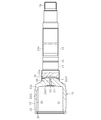
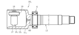
- FIG. 2 is an enlarged partial longitudinal sectional view of the outer joint member 11.
- the outer joint member 11 is open at one end, and has a bottom with a plurality of track grooves 30 and a cylindrical inner peripheral surface 42 on which balls 41 (see FIG. 1) roll at equal intervals in the circumferential direction of the inner peripheral surface.
- the outer joint member 11 is formed by welding a cup member 12a and a shaft member 13a.
- the cup member 12a is made of medium carbon steel containing 0.40 to 0.60% by weight of carbon such as S53C, and has a cylindrical portion 12a1 and a bottom portion in which a track groove 30 and a cylindrical inner peripheral surface 42 are formed on the inner periphery. 12a2 is an integrally molded product. A convex portion 12a3 is formed on the bottom portion 12a2 of the cup member 12a. A boot mounting groove 32 is formed on the outer periphery on the opening side of the cup member 12a, and a retaining ring groove 33 is formed on the inner periphery.
- the shaft member 13a has a bearing mounting surface 14 and a retaining ring groove 15 formed on the outer periphery on the cup member 12a side, and a spline Sp formed on the opposite end.
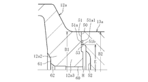
- the shaft member 13a is made of medium carbon steel containing 0.30 to 0.55 wt% carbon such as S40C. As shown in FIGS. 3a and 3b, the joining end surface 50 formed on the convex portion 12a3 of the bottom portion 12a2 of the cup member 12a and the joining end surface 51 of the end portion on the cup member 12a side of the shaft member 13a are abutted to each other. Welded by electron beam welding in the radial direction from the outside of 12a. The welded portion 49 is formed by a bead of a beam irradiated from the radially outer side of the cup member 12a.
- the outer diameters B1 and B2 of the joining end surface 50 and the joining end surface 51 are set to the same dimension for each joint size.
- the outer diameter B1 of the joining end surface 50 of the cup member 12a and the outer diameter B2 of the joining end surface 51 of the shaft member 13a are not necessarily the same size.
- the outer diameter B2 of the bonding end surface 51 is slightly smaller than the outer diameter B1 of the bonding end surface 50, and conversely, the outer diameter B2 of the bonding end surface 51 is slightly smaller than the outer diameter B1 of the bonding end surface 50.
- An appropriate dimensional difference such as a large diameter may be added.
- the outer diameters B1 and B2 of the joining end face 50 and the joining end face 51 are set to the same dimension for each joint size.
- the outer diameter B1 of the joining end face 50 and the joining end face 51 This is a concept including an appropriate dimensional difference with respect to the outer diameter B2.
- the welded portion 49 is formed on the joining end surface 51 closer to the cup member 12a than the bearing mounting surface 14 of the shaft member 13a, so that the bearing mounting surface 14 can be processed in advance and welded. Later post-processing can be abolished. Further, since burrs do not appear in the weld due to electron beam welding, post-processing of the weld can be omitted, and the manufacturing cost can be reduced. Further, 100% inspection by ultrasonic flaw detection of the welded portion is possible.
- FIGS. 3a and 3b the joining end face 50 of the cup member 12a is turned in a ring-shaped configuration, and the forging skin remains in the central portion in the radial direction. This shortens the turning time.
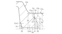
- a vent hole 60 is provided in the axial center of the cup member 12a so as to penetrate the bottom portion 12a2 of the cup member 12a.
- a counterbore 61 is provided on the bottom 12a2 of the cup member 12a, and a center hole 62 is formed in the counterbore 61.
- the center hole 62 is used for centering by fitting the center hole guide in the manufacturing process of the outer joint member 11 described later. Since the vent hole 60 is provided in the axial center of the cup member 12a, it is advantageous in terms of product strength. Further, since the center hole 62 is formed in the vent hole 60, it is advantageous in processing the center hole 62.
- a welding sputter receiving groove 51a is formed on the inner diameter side of the joining end surface 51 of the shaft member 13a, and an annular shielding part 51b is formed on the inner diameter side thereof.
- the weld sputter receiving groove 51 a is formed at the weld joint interface immediately below the bead of the weld 49.
- the hollow cavity H communicates with the outside air through the vent hole 60, when the sealed space at the time of welding is set to a medium vacuum level that establishes industrial production, a slight amount of remaining air enters the air at the time of welding.
- the weld 49 is pushed outward in the radial direction by heat, and the problem of insufficient weld length can be prevented.
- the medium vacuum means a vacuum of 100 Pa to 0.1 Pa defined by JIS 81126-1.
- the vent hole 60 Since the vent hole 60 is provided, the cup member 12a and the shaft member 13a are brought into contact with each other, and electron beam welding is performed in a medium vacuum (low pressure) atmosphere at a level that establishes industrial production of a constant velocity universal joint that is a mass-produced product.
- a medium vacuum (low pressure) atmosphere at a level that establishes industrial production of a constant velocity universal joint that is a mass-produced product.
- no dent is generated on the inner diameter side of the bead of the welded portion 49, and the inner diameter end portion of the bead of the weld 49 is sufficiently formed up to the weld sputter receiving groove 51a, so that the weld length can be secured.
- strength, quality, and reliability of a welding part can be improved.
- spatter during welding is captured by the weld sputter receiving groove 51a, and this spatter remains in the weld spatter receiving groove 51a due to the presence of the annular shielding portion 51b. For this reason, it is possible to prevent spatter from entering the cup portion 12a of the outer joint member 11, and it is possible to prevent the constant velocity universal joint 10 from being deteriorated and the NVH characteristics from being deteriorated.
- the annular shielding part 51b and the joining end face 51 are on the same plane, but a gap is set between the annular shielding part 51b and the joining end face 50 so that spatter does not flow out. Is called. It is desirable that the ratio of the gap between the annular shielding part 51b and the joining end surface 50 and the radial length of the annular shielding part 51b is 4 or more.
- the small spatter that has been confirmed by welding so far has a diameter of about 0.2 mm, and when the gap between the annular shield 51b and the joining end face 50 is 0.2 mm, it can theoretically pass through. The passage of spatter can be prevented by lengthening the length of the annular shielding portion 51b in accordance with the settable gap.
- the weld sputter receiving groove 51a has a width of about 1 to 3 mm and a depth of about 0.5 to 2 mm.
- the groove bottom corner 51a1 (see FIG. 3a) of the weld sputter receiving groove 51a is formed with an appropriate R in consideration of stress concentration.
- the welding spatter receiving groove 51a is also set to the same dimension for each joint size. For this reason, it is advantageous in terms of processing and variety integration.
- the welding spatter accommodation groove 13a can be easily formed when the shaft member 13a is turned.
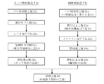
- FIG. 4 shows an outline of the manufacturing process of the outer joint member.
- the cup member 12a is manufactured by a manufacturing process including a bar material cutting process S1c, a forging process S2c, an ironing process S3c, and a turning process S4c, as shown.
- the shaft member 13a is manufactured by a manufacturing process including a bar material cutting process S1s, a turning process S2s, and a spline processing process S3s.
- the intermediate parts of the cup member 12a and the shaft member 13a manufactured in this way are each assigned a product number and managed.
- the outer joint member 11 is completed through the welding step S6, the heat treatment step S7, and the grinding step S8 of the cup member 12a and the shaft member 13a.
- Bar material cutting step S1c Based on the forging weight, the bar material is cut at a predetermined length to produce a billet.
- Forming process S2c The billet is forged, and the cylindrical part, the bottom part, and the convex part are integrally formed as a shape material of the cup member 12a.
- the manufacturing process of the shaft member 13a will be described.
- Bar material cutting process S1s Based on the total length of the shaft part, the bar material is cut at a predetermined length to produce a billet. Thereafter, depending on the shape of the shaft member 13a, the billet may be forged into an approximate shape by upset forging.
- Induction hardening and tempering are performed as heat treatment on at least the track grooves 30, the cylindrical inner peripheral surface 42 and the outer periphery of the shaft portion 13 of the cup portion 12 after welding. The weld is not heat treated.
- a hardened layer of about HRC 58 to 62 is formed on the track groove 30 and the cylindrical inner peripheral surface 42 of the cup portion 12. Further, a hardened layer of about HRC 50 to 62 is formed in a predetermined range on the outer periphery of the shaft portion 13.
- this manufacturing process incorporates a heat treatment process after the welding process, it is suitable for cup members and shaft members having shapes and specifications that affect the hardness of the heat treatment part because the temperature at the periphery increases due to the heat during welding. .
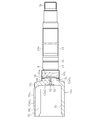
- FIG. 5A is a longitudinal sectional view showing a state after the ironing process of the cup member 12a
- FIG. 5B is a longitudinal sectional view showing a state after the turning process.
- the cylindrical portion 12a1', the bottom portion 12a2 'and the convex portion 12a3' are integrally formed in the forging step S2c.
- the track grooves 30 and the cylindrical cylindrical surface 42 are ironed, and the inner periphery of the cylindrical portion 12a1 'is finished as shown in FIG. 5a.
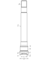
- FIG. 6 shows the state of the shaft member 13a in each processing step.
- 6a is a front view showing a billet 13a ′′ obtained by cutting a bar material
- FIG. 6b is a partial longitudinal sectional view showing a raw material 13a ′ obtained by forging the billet 13a ′′ into an approximate shape by upset forging
- FIG. It is a fragmentary longitudinal cross-section which shows the shaft member 13a after a turning process and a spline process.
- the billet 13a ′′ shown in FIG. 6a is manufactured. If necessary, as shown in FIG. 6b, the billet 13a ′′ is upset by forging and joining the shaft diameter within a predetermined range.
- a shaped member 13a ′ having a recess 52 formed on the side end (the end on the cup member 12a side) is manufactured.
- the outer diameter of the shaft member 13a, the bearing mounting surface 14, the retaining ring groove 15, the inner diameter surface 53 (inner diameter E) of the recess 52, the joining end surface 51, and the outside are turned, and the spline Sp is processed by rolling or pressing at the opposite end of the recess 52 in the spline processing step S3s.
- the outer diameter B1 of the joining end surface 50 of the cup member 12a shown in FIG. 5b is set to be the same size with one joint size.
- the shaft member 13a shown in FIG. 6c is for a long stem
- the outer diameter B2 of the joining end surface 51 is set to the same size with one joint size regardless of the shaft diameter or the outer peripheral shape.
- the joining end surface 51 of the shaft member 13 a is set at a position closer to the cup member 12 a than the bearing mounting surface 14. Since the dimensions are set in this way, the cup member 12a is shared, only the shaft member 13a is manufactured in various shaft diameters, lengths and outer peripheral shapes according to the vehicle type, and both the members 12a and 13a are welded.
- the outer joint member 11 suitable for various vehicle types can be manufactured. Details of sharing the cup member 12a will be described later.
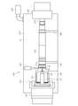
- FIGS. 7 and 8 are schematic views showing the welding apparatus.
- FIG. 7 shows a state before welding
- FIG. 8 shows a state where welding is performed.
- the welding apparatus 100 mainly includes an electron gun 101, a rotating device 102, a chuck 103, a center hole guide 104, a tail stock 105, a work cradle 106, a center hole guide 107, a case 108, and a vacuum pump 109.
- the configuration is mainly includes an electron gun 101, a rotating device 102, a chuck 103, a center hole guide 104, a tail stock 105, a work cradle 106, a center hole guide 107, a case 108, and a vacuum pump 109.
- the cup member 12a and the shaft member 13a which are workpieces, are placed on the workpiece cradle 106 in the welding apparatus 100.
- the chuck 103 and the center hole guide 107 at one end of the welding apparatus 100 are connected to the rotating device 102, and the cup member 12a is fitted by the chuck 103 with the center hole guide 107 fitted into the center hole 62 and the cup member 12a being centered.
- a center hole guide 104 is integrally attached to a tail stock 105 at the other end of the welding apparatus 100, and both are configured to be able to advance and retract in the axial direction (left and right direction in FIGS. 7 and 8).
- the center hole of the shaft member 13a is set in the center hole guide 104 and is centered.
- a vacuum pump 109 is connected to the case 108 of the welding apparatus 100.
- the sealed space means a space 111 formed by the case 108.
- the entire cup member 12 a and the shaft member 13 a are accommodated in the sealed space 111.
- An electron gun 101 is provided at a position corresponding to the joining end faces 50 and 51 of the cup member 12a and the shaft member 13a. The electron gun 101 is configured to be close to a predetermined position with respect to the workpiece.
- the cup member 12a and the shaft member 13a which are workpieces, are stocked at a place different from the welding apparatus 100.
- Each workpiece is taken out by, for example, a robot, conveyed into the case 108 of the welding apparatus 100 opened to the atmosphere shown in FIG. 7, and set at a predetermined position of the workpiece cradle 106.
- the center hole guide 104 and the tail stock 105 are retracted to the right in the drawing, and a gap is provided between the joining end surfaces 50 and 51 of the cup member 12a and the shaft member 13a.
- the door (not shown) of the case 108 is closed, and the vacuum pump 109 is activated to depressurize the sealed space 111 formed in the case 108.
- the recessed part 52 of the shaft member 13a, the internal diameter part 53, and the inside of the vent hole 60 are also decompressed.
- the center hole guide 104 and the tail stock 105 move forward to the left, and the gaps between the end surfaces 50 and 51 for joining the cup member 12a and the shaft member 13a are formed. Disappear.
- the cup member 12 a is centered by fitting the center hole guide 107 into the center hole 62 and fixed by the chuck 103, and the shaft member 13 a is supported by the center hole guide 104.
- the work cradle 106 moves away from the work. Since the distance between the workpiece cradle 106 and the workpiece at this time may be very small, the above-described interval is not shown in FIG. Of course, it is possible to have a structure in which the workpiece cradle 106 is largely retracted downward.
- the electron gun 101 approaches the work to a predetermined position, rotates the work, and starts preheating.
- the preheating condition is set to a temperature lower than the welding temperature by, for example, irradiating the electron gun 101 close to the workpiece and irradiating the electron beam with a large spot diameter. By preheating, burning cracks can be prevented by slowing the cooling rate after welding.
- the electron gun 101 is retracted to a predetermined position, and an electron beam is irradiated in the radial direction from the outside of the workpiece to start welding.
- the shaft member 13a has a weld sputter receiving groove 51a formed in the weld joint interface immediately below the bead of the welded portion 49 on the inner diameter side of the joining end face 51.
- An annular shield 51b is formed.
- a gap is set between the annular shielding portion 51b and the joining end face 50 so that the spatter does not flow out, and ventilation is performed through the gap.
- the hollow cavity H formed between the cup member 12 a and the shaft member 13 a communicates with the outside air through the vent hole 60.
- the center hole guide 107 is fitted into the center hole 62 provided in the vent hole 60, but air flows back and forth through the contact portion by the fitting.
- the hollow cavity H communicates with the outside air through the vent hole 60, when the medium vacuum is set to a level that establishes industrial production at the time of welding, a slight amount of air remains as heat input at the time of welding.
- the welded portion 49 is not pushed outward in the radial direction, and the weld length can be secured.
- spatter during welding is captured by the weld sputter receiving groove 51a, and this spatter remains in the weld spatter receiving groove 51a due to the presence of the annular shielding portion 51b.
- the sealed space 111 is opened to the atmosphere. Then, with the workpiece cradle 106 raised and supporting the workpiece, the center hole guide 104 and the tail stock 105 are retracted to the right, and the chuck 103 is released. Thereafter, for example, the robot grabs the workpiece, removes it from the welding apparatus 100, and aligns it with the cooling stocker.
- the configuration of the sealed space 111 in the case 108 can be simplified.
- the above-described welding apparatus 100 uses the cup member 12a.
- the pressure in the sealed space 111 was set to 6.7 Pa or less for welding.
- Electron beam welding was performed.
- a welded portion 49 having a raised height (0.5 mm or less) on the weld surface that does not affect the incorporation of the bearing 6 into the shaft portion of the outer joint member 11 was obtained. Further, by the soaking by preheating, the weld zone hardness after completion of welding could be suppressed within the range of Hv 200 to 500, and the welding strength was high and stable welding condition and quality could be obtained. Furthermore, by welding the sealed space 111 of the welding apparatus 100 at atmospheric pressure or lower, it is possible to suppress a pressure change in the hollow cavity during welding, and to prevent the melt from being blown up or drawn into the inner diameter side. did it.
- the setting of the pressure 6.7 Pa or less in the sealed space 111 in the case 108 is a vacuum (low pressure) condition at a level that establishes industrial production of a constant velocity universal joint that is a mass-produced product for automobiles and the like.
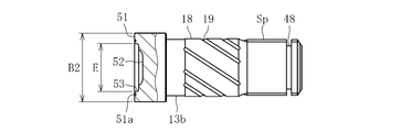
- the shaft member 13b shown in FIGS. 9 and 10 is for a standard stem on the inboard side.
- the shaft member 13b is formed with a joining end surface 51 that abuts the joining end surface 50 (see FIG. 5b) of the bottom 12a2 (projection 12a3) of the cup member 12a.
- the outer diameter B2 and the inner diameter E of the joining end face 51 are formed to have the same dimensions as the outer diameter B1 and the inner diameter E of the joining end face 51 of the long stem type shaft member 13a shown in FIG. 6c.
- this shaft member 13b is for a standard stem on the inboard side, the length of the shaft portion is short, and a sliding bearing surface 18 is formed in the central portion in the axial direction, and a plurality of oil grooves 19 are formed on this sliding bearing surface 18. Is formed.
- a spline Sp and a retaining ring groove 48 are formed at the end opposite to the cup member 12a side.
- the outer diameter B2 of the joining end surface 51 of the shaft members 13a and 13b is different even if the stem length or the long stem of the standard length is different or the various shaft diameters and outer peripheral shapes are different for each vehicle type. The same dimensions are set.
- the welding sputter accommodation groove 51a of the shaft members 13a and 13b is also set to the same dimension for each joint size.
- the cup member and the vehicle type that are shared for each joint size are used.
- a shaft member having various shaft specifications can be prepared in a state before heat treatment, and can be managed by assigning a product number to each of the intermediate parts of the cup member 12a and the shaft members 13a and 13b. And even if the cup member 12a is integrated, various outer joint members 11 according to requirements can be quickly manufactured in combination with shaft members 13a and 13b having various shaft specifications for each vehicle type. . Therefore, it is possible to reduce the cost and production management load by integrating the types of cup members 12a.
- cup members In the above, for the sake of easy understanding, the type integration of cup members has been explained by taking the difference between the standard length stem and the long stem as an example, but the standard length is not limited to this. This also applies to the integration of cup members with respect to shaft members having various shaft specifications for each vehicle type between the stems and shaft members having various shaft specifications for each vehicle type between the long stems.
- FIG. 11 shows an example of product type integration of cup members of this embodiment.
- the cup member is shared by one joint size, and is managed with, for example, a product number C001.
- the shaft member has various shaft part specifications for each vehicle type, and is managed by being assigned product numbers S001, S002, to S (n), for example.
- product numbers S001, S002, to S (n) for example.
- the integration of the cup member types can reduce the cost and the production management load.
- the cup member is not limited to one type with one joint size, that is, one model number. For example, a plurality of types (multiple types with one joint size according to specifications with different maximum operating angles). Model number) cup members are set, and those having the same outer diameter B1 of the joining end faces of these cup members are wrapped.
- FIG. 12A is a longitudinal sectional view showing a state before welding
- FIG. 12B is a longitudinal sectional view showing a state after welding.
- Welding spatter receiving grooves 51a 1 of the present modification is directed to copying shape groove face of the inner diameter side is formed to be inclined. Therefore, it is possible to process and connecting the end faces 51 1 to weld spatter receiving groove 51a 1 by turning copying during turning of the joining end surface 51 1 of the shaft member 13a 1 in one step, weld spatter accommodated by parting bytes groove possible to shorten the turning step is omitted additional turning steps 51a 1.
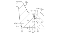
- FIG. 13a is a longitudinal sectional view showing a state before welding
- FIG. 13b is a longitudinal sectional view showing a state after welding.
- Welding spatter receiving groove 50a 1 of the present modification forms the joining end face 50 1 of the cup member 12a 1, weld spatter accommodating grooves 50a 1 inner diameter side to the inner diameter surface (inner diameter E) the points forming the first Different from the outer joint member of the embodiment. Since other configurations are the same as those of the outer joint member 11 of the first embodiment, parts having the same functions are denoted by the same reference numerals (excluding subscripts), and the parts of the first embodiment. All the above-described contents of the outer joint member and the manufacturing method thereof apply mutatis mutandis, and the description thereof is omitted.
- FIG. 14 shows a modification of the method for manufacturing the outer joint member.
- the heat treatment process of the cup member in the heat treatment process S7 of FIG. 4 described above is incorporated before the welding process S6 to form a heat treatment process S5c, and the cup member is prepared as a finished product.
- Contents excluding this point that is, the outline of each process described above in the outer joint member of the first embodiment, the state in the main processing steps of the cup member and the shaft member, common use of the cup member, welding method, product type integration Since the structure of the outer joint member and the like are the same, all the contents of the first embodiment are applied mutatis mutandis to the present modification, and only different portions will be described.
- the cup member 12a has a shape extending from the joining end face 50 to the cylindrical portion 12a1 having a large diameter through the bottom portion 12a2, and the portion subjected to heat treatment as quenching and tempering is the cylindrical portion 12a1.
- the cup member 12a can be manufactured independently up to a finished product that has undergone forging, turning, and heat treatment, and productivity is improved including reduction of setup.
- the part number of the cup member in the drawing is only the part number as the finished product. Since the shaft member and the outer joint member are the same as those in the first embodiment, description thereof will be omitted.
- FIG. 15 shows another modification of the method for manufacturing the outer joint member.
- the heat treatment process S5c of the cup member is incorporated by incorporating the heat treatment process of the cup part and the shaft part and the grinding process S8 of the shaft part of the heat treatment process S7 of FIG. 4 before the welding process S6.
- the shaft member heat treatment step S4s and the grinding step S5s are performed. Therefore, both the cup member and the shaft member are prepared as finished products.
- the shaft member is formed with a hardened layer of about HRC 50 to 62 by induction hardening in a predetermined range of the outer peripheral surface in the heat treatment step S4s after the spline processing step S3s.
- the predetermined axial direction portion including the joining end face 51 is not subjected to heat treatment.
- duplication description is abbreviate
- the shaft member is moved to the grinding step S5s to finish the bearing mounting surface 14 and the like. Thereby, the shaft member as a finished product is obtained. Then, a product number as a finished product is assigned to the shaft member and managed.
- the manufacturing process of this modification is suitable for the case of a cup member and a shaft member having a shape and specifications that do not cause a thermal effect during welding on the heat treatment part.
- both the cup member and the shaft member can be managed by assigning product numbers as finished products. Therefore, the cost reduction and the production management load reduction due to the integration of the types of cup members become more remarkable. Further, the cup member and the shaft member can be separately manufactured up to a finished product that has undergone forging, turning, heat treatment, grinding after heat treatment, and the like, and the productivity is further improved, including reduction of setup.
- the product numbers of the cup member and the shaft member in the drawing are the product numbers of the finished products. . Since the outer joint member is the same as that of the first embodiment, the description thereof is omitted.
- the cup member and the shaft member as a finished part are not limited to those subjected to the finishing process such as the grinding process after the heat treatment and the post-quenching cutting process described above, and the heat-treated cup with the finishing process remaining. It includes members and shaft members.
- the cup member is not limited to one type of joint size, that is, one model number. That is, as described above, for example, a plurality of types (plural model numbers) of cup members are set with a single joint size according to different specifications of the maximum operating angle, and the outer diameters B1 of the joining end surfaces of these cup members are the same. Wrapping what is dimensioned. In addition to this, in order to manage the cup member in multiple forms of intermediate parts and finished parts before heat treatment in consideration of, for example, joint functions, actual conditions at the manufacturing site, productivity, etc. These types (multiple model numbers) of cup members are set, and those having the same outer diameter B1 of the joining end faces of these cup members are also included.
- Sliding type constant velocity universal joint 10 2 shown in FIG. 16 is a tripod type constant velocity universal joint (TJ), and a long stem portion 13 extending axially from the bottom of the cup portion 12 2 and the cup portion 12 2 an outer joint member 11 2 having an outer joint member 11 2 of the cup portion 12 the inner joint member 16 2 accommodated in the inner circumference of the 2, disposed between the outer joint member 11 2 and the inner joint member 16 2 And a roller 19 as a torque transmission element.
- the inner joint member 16 2 is composed of a tripod member 17 three trunnions 18 which the roller 19 externally fitted is provided at equal circumferential intervals.
- An inner ring of the support bearing 6 is fixed to the outer peripheral surface of the long stem portion 13, and the outer ring of the support bearing 6 is fixed to the transmission case via a bracket (not shown).
- the outer joint member 11 2 is rotatably supported by the support bearing 6, deflection of the outer joint member 11 2 at the operating time or the like is prevented as much as possible.
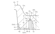
- Figure 17 shows a partial longitudinal section of the outer joint member 11 2.
- the outer joint member 11 2 has one end open, the inner roller 19 in the circumferential direction trisected position in the circumferential surface (see FIG. 16) to roll the track grooves 30 2 and the inner circumferential surface 31 2 spline Sp of but a bottomed cylindrical cup portion 12 2 formed, extending axially from the bottom of the cup portion 12 2, as the torque transmitting connection portion to the outer circumference of the end portion of the opposite side of the cup portion 12 2 side And a long stem portion 13 provided with.
- the outer joint member 11 2, the cup member 12a 2 and the shaft member 13a is formed by welding.
- the cup member 12a 2 is a single piece consisting of an inner cylindrical portion inner peripheral surface 31 2 and the track grooves 30 2 are formed on the peripheral 12a1 2 and the bottom 12a2 2.
- the bottom 12a2 2 of the cup member 12a 2 projecting portion 12a3 2 is formed.
- a boot mounting groove 32 is formed on the outer periphery of the cup member 12a 2 on the opening side.
- the shaft member 13a is a bearing mounting surface 14 and retaining ring groove 15 on the outer periphery of the cup member 12a 2 side is formed a spline Sp is formed at the opposite end from the cup member 12a 2 side.
- Weld 49 is formed at the bead emitted from the radially outer side of the cup member 12a 2.
- provided weld spatter housing groove 51a on the inner diameter side of the joint end face 51 of the shaft member 13a is in the hollow cavity H at the bottom 12a2 2 the axis of the cup member 12a2
- a vent hole 60 is provided.
- the outer diameter of the joining end face 50 2 and connecting end face 51 is set to the same size for each joint size.
- Weld 49 because it is formed in the bearing mounting surface 14 cup member 12a 2 side of the joint end face 51 than the shaft member 13a, etc. bearing mount surface 14 can be eliminated post-processing after the pre-processable welding. Further, since burrs do not appear in the weld due to electron beam welding, post-processing of the weld can be omitted, and the manufacturing cost can be reduced.
- the outer joint member 11 2 is the same as the contents described above in the outer joint member 11 according to the first embodiment described above, the steps described above in the outer joint member of the first embodiment Since the outline, the state in the main processing steps of the cup member and the shaft member, the common use of the cup member, the welding method, the product type integration, the configuration of the outer joint member, etc. are the same, all the contents of the first embodiment are described here. The same applies to the embodiment, and the description is omitted.
- the electron beam welding is applied.
- laser welding can be similarly applied.
- the present invention can also be applied to an outer joint member of another sliding type constant velocity universal joint such as a type constant velocity universal joint, and further to an outer joint member of a fixed type constant velocity universal joint.
- the present invention is applied to the outer joint member of the constant velocity universal joint constituting the drive shaft.
- the present invention is also applied to the outer joint member of the constant velocity universal joint constituting the propeller shaft. Can do.
Landscapes
- Engineering & Computer Science (AREA)
- Mechanical Engineering (AREA)
- General Engineering & Computer Science (AREA)
- Physics & Mathematics (AREA)
- Optics & Photonics (AREA)
- Plasma & Fusion (AREA)
- Welding Or Cutting Using Electron Beams (AREA)
- Laser Beam Processing (AREA)
- Shafts, Cranks, Connecting Bars, And Related Bearings (AREA)
Abstract
L'invention concerne des éléments de joint externe (11 et 112) d'un joint universel homocinétique (10) qui sont formés en configurant : des parties bonnet (12, 121 et 122) comportant une rainure (30) de piste formée dans une circonférence interne associée, de sorte que des éléments de transmission de couple (19 et 23) soient en prise avec la rainure (30) de piste ; et une partie arbre (13) formée sur les parties inférieures des parties bonnet (12, 121 et 122) de différents éléments et en appuyant en butée les éléments (12a, 12a2 et 12a2) de bonnet formant les parties bonnet (12, 121 et 122) contre des éléments (13a et 13a2) d'arbre formant la partie arbre (13) et en les soudant. L'invention est caractérisée en ce que, dans l'élément de joint externe (11) du joint universel homocinétique (10), dans lequel est formée une cavité creuse (H) en appuyant en butée des faces d'extrémité de jonction (50, 501 et 502) des éléments (12a, 12a2 et 12a2) de bonnet contre des faces d'extrémité de jonction (51 et 511) des éléments (13a et 13a2) d'arbre, un trou d'air (60) communiquant avec des cavités creuses (H et H1) est prévu au niveau du centre d'arbre des éléments (12a, 12a2 et 12a2) de bonnet et des rainures d'accueil de pulvérisation cathodique de soudage (50a1, 51a et 51a1) sont formées sur le côté diamètre interne des faces d'extrémité de jonction (50, 501 et 502) des éléments (12a, 12a2 et 12a2) de bonnet ou des faces d'extrémité de jonction (51 et 511) des éléments (13a et 13a2) d'arbre.
Priority Applications (3)
| Application Number | Priority Date | Filing Date | Title |
|---|---|---|---|
| EP16807362.5A EP3309420B1 (fr) | 2015-06-11 | 2016-06-01 | Élément de joint externe d'un joint universel homocinétique |
| CN201680033368.5A CN107614910B (zh) | 2015-06-11 | 2016-06-01 | 等速万向联轴器的外侧联轴器构件 |
| US15/580,013 US10774878B2 (en) | 2015-06-11 | 2016-06-01 | Outer joint member of a constant velocity universal joint |
Applications Claiming Priority (2)
| Application Number | Priority Date | Filing Date | Title |
|---|---|---|---|
| JP2015118207A JP6639811B2 (ja) | 2015-06-11 | 2015-06-11 | 等速自在継手の外側継手部材 |
| JP2015-118207 | 2015-06-11 |
Publications (1)
| Publication Number | Publication Date |
|---|---|
| WO2016199655A1 true WO2016199655A1 (fr) | 2016-12-15 |
Family
ID=57503610
Family Applications (1)
| Application Number | Title | Priority Date | Filing Date |
|---|---|---|---|
| PCT/JP2016/066317 Ceased WO2016199655A1 (fr) | 2015-06-11 | 2016-06-01 | Élément de joint externe d'un joint universel homocinétique |
Country Status (5)
| Country | Link |
|---|---|
| US (1) | US10774878B2 (fr) |
| EP (1) | EP3309420B1 (fr) |
| JP (1) | JP6639811B2 (fr) |
| CN (1) | CN107614910B (fr) |
| WO (1) | WO2016199655A1 (fr) |
Families Citing this family (4)
| Publication number | Priority date | Publication date | Assignee | Title |
|---|---|---|---|---|
| CN108655556A (zh) * | 2018-08-06 | 2018-10-16 | 湖南南方通用航空发动机有限公司 | 一种基于电子束焊加工带锁底对接接头的方法 |
| JP7412099B2 (ja) * | 2019-07-05 | 2024-01-12 | Ntn株式会社 | 動力伝達機構及び車両 |
| CN113710406B (zh) * | 2019-12-19 | 2024-02-23 | 株式会社Lg新能源 | 电池模块和制造该电池模块的方法 |
| DE102022203695A1 (de) | 2022-04-12 | 2023-10-12 | Mahle International Gmbh | Verfahren zum Verbinden eines ersten Bauteils mit einem zweiten Bauteil mittels Laserschweißen und Wellenanordnung |
Citations (7)
| Publication number | Priority date | Publication date | Assignee | Title |
|---|---|---|---|---|
| JPS61273275A (ja) * | 1985-05-29 | 1986-12-03 | Ishikawajima Harima Heavy Ind Co Ltd | ビ−ム溶接方法 |
| JPH0259892U (fr) * | 1988-10-24 | 1990-05-01 | ||
| JPH0525601B2 (fr) * | 1981-09-21 | 1993-04-13 | Toyota Motor Co Ltd | |
| JP2000329151A (ja) * | 1999-05-17 | 2000-11-28 | Honda Motor Co Ltd | 等速ジョイント用外輪部材の接合方法および装置 |
| JP2013002586A (ja) * | 2011-06-20 | 2013-01-07 | Ntn Corp | 等速自在継手の外側継手部材 |
| JP2013094783A (ja) * | 2011-10-28 | 2013-05-20 | Fuji Heavy Ind Ltd | 被加工物の加工方法 |
| JP2015064101A (ja) * | 2013-08-29 | 2015-04-09 | Ntn株式会社 | 等速自在継手の外側継手部材の製造方法および外側継手部材 |
Family Cites Families (7)
| Publication number | Priority date | Publication date | Assignee | Title |
|---|---|---|---|---|
| JPH0259892A (ja) | 1988-08-25 | 1990-02-28 | Tokyo Electric Co Ltd | 商品販売データ処理装置 |
| DE4039597A1 (de) * | 1990-12-12 | 1992-06-17 | Gkn Automotive Ag | Tripodengelenk |
| JP3034082B2 (ja) * | 1991-07-22 | 2000-04-17 | 川崎製鉄株式会社 | 錫めっき鋼板のリフロー処理方法 |
| DE102004015440B4 (de) * | 2004-03-30 | 2021-06-17 | Robert Bosch Gmbh | Schweißverbindung zwischen einem dickwandigen Bauteil und einem dünnwandigem Bauteil sowie Kraftstoffhochdruckpumpe für eine Brennkraftmaschine |
| CN101098768B (zh) * | 2004-11-30 | 2010-09-29 | 约翰逊控制技术公司 | 连接构件 |
| JP5901940B2 (ja) * | 2011-11-08 | 2016-04-13 | Ntn株式会社 | 等速自在継手の外側継手部材の溶接方法 |
| ES2671494T3 (es) * | 2013-12-17 | 2018-06-06 | Dana Automotive Systems Group, Llc | Junta homocinética |
-
2015
- 2015-06-11 JP JP2015118207A patent/JP6639811B2/ja active Active
-
2016
- 2016-06-01 WO PCT/JP2016/066317 patent/WO2016199655A1/fr not_active Ceased
- 2016-06-01 CN CN201680033368.5A patent/CN107614910B/zh active Active
- 2016-06-01 US US15/580,013 patent/US10774878B2/en active Active
- 2016-06-01 EP EP16807362.5A patent/EP3309420B1/fr active Active
Patent Citations (7)
| Publication number | Priority date | Publication date | Assignee | Title |
|---|---|---|---|---|
| JPH0525601B2 (fr) * | 1981-09-21 | 1993-04-13 | Toyota Motor Co Ltd | |
| JPS61273275A (ja) * | 1985-05-29 | 1986-12-03 | Ishikawajima Harima Heavy Ind Co Ltd | ビ−ム溶接方法 |
| JPH0259892U (fr) * | 1988-10-24 | 1990-05-01 | ||
| JP2000329151A (ja) * | 1999-05-17 | 2000-11-28 | Honda Motor Co Ltd | 等速ジョイント用外輪部材の接合方法および装置 |
| JP2013002586A (ja) * | 2011-06-20 | 2013-01-07 | Ntn Corp | 等速自在継手の外側継手部材 |
| JP2013094783A (ja) * | 2011-10-28 | 2013-05-20 | Fuji Heavy Ind Ltd | 被加工物の加工方法 |
| JP2015064101A (ja) * | 2013-08-29 | 2015-04-09 | Ntn株式会社 | 等速自在継手の外側継手部材の製造方法および外側継手部材 |
Non-Patent Citations (1)
| Title |
|---|
| See also references of EP3309420A4 * |
Also Published As
| Publication number | Publication date |
|---|---|
| EP3309420A1 (fr) | 2018-04-18 |
| EP3309420B1 (fr) | 2025-11-05 |
| US20180180101A1 (en) | 2018-06-28 |
| CN107614910B (zh) | 2020-07-21 |
| US10774878B2 (en) | 2020-09-15 |
| JP2017003027A (ja) | 2017-01-05 |
| CN107614910A (zh) | 2018-01-19 |
| EP3309420A4 (fr) | 2019-02-27 |
| JP6639811B2 (ja) | 2020-02-05 |
Similar Documents
| Publication | Publication Date | Title |
|---|---|---|
| JP6316659B2 (ja) | 等速自在継手の外側継手部材の製造方法および外側継手部材 | |
| JP5901940B2 (ja) | 等速自在継手の外側継手部材の溶接方法 | |
| JP6104598B2 (ja) | 等速自在継手の外側継手部材の製造方法 | |
| WO2016199655A1 (fr) | Élément de joint externe d'un joint universel homocinétique | |
| JP6347994B2 (ja) | 等速自在継手の外側継手部材の製造方法および外側継手部材 | |
| JP6320855B2 (ja) | 等速自在継手の外側継手部材の製造方法および外側継手部材 | |
| JP6338912B2 (ja) | 突合せ溶接用芯出し方法及び装置 | |
| JP6385730B2 (ja) | 等速自在継手の外側継手部材の製造方法および外側継手部材 | |
| JP6719895B2 (ja) | 等速自在継手の外側継手部材 | |
| JP6472611B2 (ja) | 等速自在継手の外側継手部材の製造方法 | |
| JP2020148281A (ja) | 等速自在継手の製造方法 | |
| WO2017061208A1 (fr) | Élément de joint externe pour joint homocinétique universel | |
| JP2017106487A (ja) | 等速自在継手の外側継手部材 |
Legal Events
| Date | Code | Title | Description |
|---|---|---|---|
| 121 | Ep: the epo has been informed by wipo that ep was designated in this application |
Ref document number: 16807362 Country of ref document: EP Kind code of ref document: A1 |
|
| WWE | Wipo information: entry into national phase |
Ref document number: 15580013 Country of ref document: US |
|
| NENP | Non-entry into the national phase |
Ref country code: DE |
|
| WWG | Wipo information: grant in national office |
Ref document number: 2016807362 Country of ref document: EP |