WO2016199848A1 - Générateur de puissance sans contact - Google Patents
Générateur de puissance sans contact Download PDFInfo
- Publication number
- WO2016199848A1 WO2016199848A1 PCT/JP2016/067205 JP2016067205W WO2016199848A1 WO 2016199848 A1 WO2016199848 A1 WO 2016199848A1 JP 2016067205 W JP2016067205 W JP 2016067205W WO 2016199848 A1 WO2016199848 A1 WO 2016199848A1
- Authority
- WO
- WIPO (PCT)
- Prior art keywords
- magnet
- moving body
- magnetic flux
- main surface
- coil
- Prior art date
- Legal status (The legal status is an assumption and is not a legal conclusion. Google has not performed a legal analysis and makes no representation as to the accuracy of the status listed.)
- Ceased
Links
Images






Classifications
-
- H—ELECTRICITY
- H02—GENERATION; CONVERSION OR DISTRIBUTION OF ELECTRIC POWER
- H02K—DYNAMO-ELECTRIC MACHINES
- H02K7/00—Arrangements for handling mechanical energy structurally associated with dynamo-electric machines, e.g. structural association with mechanical driving motors or auxiliary dynamo-electric machines
- H02K7/18—Structural association of electric generators with mechanical driving motors, e.g. with turbines
- H02K7/1807—Rotary generators
- H02K7/1853—Rotary generators driven by intermittent forces
-
- H—ELECTRICITY
- H02—GENERATION; CONVERSION OR DISTRIBUTION OF ELECTRIC POWER
- H02K—DYNAMO-ELECTRIC MACHINES
- H02K35/00—Generators with reciprocating, oscillating or vibrating coil system, magnet, armature or other part of the magnetic circuit
- H02K35/02—Generators with reciprocating, oscillating or vibrating coil system, magnet, armature or other part of the magnetic circuit with moving magnets and stationary coil systems
-
- H—ELECTRICITY
- H02—GENERATION; CONVERSION OR DISTRIBUTION OF ELECTRIC POWER
- H02K—DYNAMO-ELECTRIC MACHINES
- H02K17/00—Asynchronous induction motors; Asynchronous induction generators
- H02K17/42—Asynchronous induction generators
-
- H—ELECTRICITY
- H02—GENERATION; CONVERSION OR DISTRIBUTION OF ELECTRIC POWER
- H02K—DYNAMO-ELECTRIC MACHINES
- H02K49/00—Dynamo-electric clutches; Dynamo-electric brakes
- H02K49/02—Dynamo-electric clutches; Dynamo-electric brakes of the asynchronous induction type
-
- H—ELECTRICITY
- H02—GENERATION; CONVERSION OR DISTRIBUTION OF ELECTRIC POWER
- H02K—DYNAMO-ELECTRIC MACHINES
- H02K7/00—Arrangements for handling mechanical energy structurally associated with dynamo-electric machines, e.g. structural association with mechanical driving motors or auxiliary dynamo-electric machines
- H02K7/18—Structural association of electric generators with mechanical driving motors, e.g. with turbines
- H02K7/1869—Linear generators; sectional generators
-
- H—ELECTRICITY
- H02—GENERATION; CONVERSION OR DISTRIBUTION OF ELECTRIC POWER
- H02K—DYNAMO-ELECTRIC MACHINES
- H02K7/00—Arrangements for handling mechanical energy structurally associated with dynamo-electric machines, e.g. structural association with mechanical driving motors or auxiliary dynamo-electric machines
- H02K7/18—Structural association of electric generators with mechanical driving motors, e.g. with turbines
- H02K7/1869—Linear generators; sectional generators
- H02K7/1876—Linear generators; sectional generators with reciprocating, linearly oscillating or vibrating parts
-
- H—ELECTRICITY
- H02—GENERATION; CONVERSION OR DISTRIBUTION OF ELECTRIC POWER
- H02K—DYNAMO-ELECTRIC MACHINES
- H02K7/00—Arrangements for handling mechanical energy structurally associated with dynamo-electric machines, e.g. structural association with mechanical driving motors or auxiliary dynamo-electric machines
- H02K7/18—Structural association of electric generators with mechanical driving motors, e.g. with turbines
- H02K7/1892—Generators with parts oscillating or vibrating about an axis
Definitions
- the present invention relates to a non-contact power generator that generates power without contact.
- US Patent Publication No. 2014/0132155 discloses a dynamo for a bicycle that generates power without contact.
- the outer peripheral surface of an annular permanent magnet that rotates around a rotation axis extending in a direction orthogonal to the rotation axis of the bicycle wheel is separated from one side surface that is continuous with the outer peripheral surface of the wheel. It is arranged.
- a permanent magnet has a plurality of magnetic poles arranged in the circumferential direction, and the magnetization directions of the adjacent magnetic poles are reversed. For example, when the wheel rotates with the N pole of the permanent magnet opposed to one side of the wheel, an eddy current is generated on one side of the wheel in a direction that prevents a change in magnetic flux from the permanent magnet.
- the permanent magnet rotates in the rotation direction of the wheel by the repulsive force and the attractive force of the magnetic flux caused by the eddy current and the magnetic flux from the permanent magnet.
- the induction power can be taken out from the coil.
- a single-phase coil is wound around a permanent magnet.
- a single-phase coil cannot effectively use the magnetic flux of a portion of the permanent magnet where the coil is not wound. Can not be increased.
- the direction of the polarity of the permanent magnet around the coil is symmetric about the rotation axis, the total amount of magnetic flux that interlinks the coil always cancels out. .
- the present invention has been made in view of the above-described problems, and an object of the present invention is to provide a non-contact power generator with good magnetic efficiency and less magnetic flux leakage.
- the present embodiment along the axis extending in the moving direction of the moving body, arranged opposite to and separated from one main surface of the moving body that moves in one direction and the opposite direction of the one direction.
- a magnet that generates a magnetic flux that passes through the one main surface A coil that is spaced apart from the surface opposite to the surface facing the one main surface of the magnet, and the magnetic flux from the magnet interlinks;
- a magnetic flux guide member disposed in at least a part of a magnetic path through which the magnetic flux interlinking the coil passes, The magnet is moved along the axis by a reaction force acting on the magnet based on an eddy current generated in a direction that prevents a change in magnetic flux from the magnet on the one main surface of the moving body.
- a non-contact power generator that moves in a moving direction at a speed slower than the moving speed of the moving body.
- the distance between the surface of the magnet facing the one main surface of the moving body and the one main surface may be the same while the magnet moves along the axis.
- the movable body in which convex portions and concave portions are alternately arranged on one main surface side is arranged to be opposed to and separated from the one main surface, and the convex portions and the concave portions are arranged in a line.
- a magnet that is movable along an axis extending in a moving direction of the moving body that moves in a direction or a reciprocating direction, and generates a magnetic flux that passes through the one main surface;
- a biasing member that biases the magnet along the axis;
- a coil disposed away from a surface opposite to the surface facing the one main surface of the magnet, and a magnetic flux from the magnet interlinks;
- a magnetic flux guide member disposed in at least a part of a magnetic path through which the magnetic flux interlinking the coil passes,
- the magnet has a reaction force acting on the magnet based on an eddy current generated on the convex portion and a surface between the convex portion and the opposing surface of the magnet when the convex portion is disposed opposite the magnet.
- the reluctance force acting on the moving body moves in the moving direction of the moving body along the axis, and the moving portion is moved by the urging force of the urging member when the concave portion is arranged to face the magnet.
- a non-contact generator is provided that moves in a direction opposite to the direction of body movement.
- the moving body in which the first portions and the second portions having at least one of permeability and conductivity lower than those of the first portions are alternately arranged on a flat main surface.
- the first and second parts are arranged opposite to each other at a distance from one main surface, and are movable along an axis extending in the moving direction of the moving body moving in the direction in which the first and second parts are arranged, and pass through the one main surface.
- a magnet that generates magnetic flux A biasing member that biases the magnet along the axis; A coil disposed away from a surface opposite to the surface facing the one main surface of the magnet, and a magnetic flux from the magnet interlinks; A magnetic flux guide member disposed in a part of a magnetic path through which the magnetic flux interlinking the coil passes, The magnet has a reaction force acting on the magnet based on an eddy current generated on the first portion when the first portion is disposed to face the magnet, and a facing surface of the first portion and the magnet. And the reluctance force acting between the second member and the magnet is moved in the moving direction along the axis and the second portion is disposed opposite to the magnet.
- a non-contact generator that moves in a direction opposite to the moving direction of the moving body is provided by the force.
- the magnet moves more influenced by the reluctance force than the reaction force.
- the coil may be a planar coil arranged in a direction intersecting the direction of magnetic flux from the magnet,
- the magnetic flux guide member may be disposed on the opposite side of the magnet with the coil interposed therebetween.
- the moving body in which convex portions and concave portions are alternately arranged on one main surface side is arranged apart from the one main surface, and moves in the direction in which the convex portions and the concave portions are arranged.
- a magnet which is rotatable around an axis extending in a direction intersecting with the moving direction of the moving body and is magnetized in a direction toward the one main surface or in the opposite direction;
- a biasing member that biases the magnet in the rotation direction of the shaft;
- a coil that is spaced apart from the surface opposite to the surface facing the one main surface of the magnet, and the magnetic flux from the magnet interlinks;
- a magnetic flux guide member disposed in at least a part of a magnetic path through which the magnetic flux interlinking the coil passes,
- the magnet has a reaction force acting on the magnet based on an eddy current generated on the convex portion and a surface between the convex portion and the opposing surface of the magnet when the convex portion is disposed opposite the magnet.
- a non-contact generator that rotates around the axis in a direction opposite to the rotation direction is provided.
- the moving body in which the first portions and the second portions having at least one of permeability and conductivity lower than those of the first portions are alternately arranged on a flat main surface.
- the first main surface is arranged apart from one main surface and is rotatable about an axis extending in a direction intersecting a moving direction of the moving body moving in a direction in which the first part and the second part are arranged.
- the magnet may be a cylindrical body disposed on the outer peripheral surface side of the shaft,
- the coil may be arranged in a circular arc shape along at least a part of the outer peripheral surface of the magnet,
- the magnetic flux guide member may be disposed to face a surface of the coil opposite to the surface facing the magnet.
- a magnet that is disposed to face and separate from one main surface of the moving body that moves in the first direction; A biasing member that biases the magnet in the first direction or in a direction opposite to the first direction; A shaft member disposed apart from the magnet and extending in a second direction intersecting the first direction; A connecting member connected to the magnet and the shaft member, and rotating the magnet around the shaft member; A coil in which the magnetic flux of the magnet is linked, The magnet is based on an eddy current generated in a direction that prevents a change in magnetic flux from the magnet on the one main surface of the moving body while the moving body moves in the first direction.
- a non-contact generator that vibrates in the first direction and in the opposite direction of the first direction is provided by the reaction force acting on the urging force and the urging force by the urging member.
- the magnet may be a permanent magnet or an electromagnet.
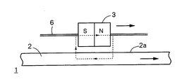
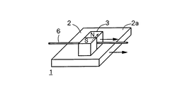
- the front view of the non-contact generator by the 1st Embodiment of the present invention The schematic diagram which shows the flow of the magnetic flux of the non-contact generator of FIG.
- FIG. 6 is a front view showing an example in which a non-contact generator having the same structure as that of FIG. 5 is disposed in close proximity to one flat main surface of a moving body.
- the non-contact generator may have a configuration and operation omitted in the following description. However, these omitted configurations and operations are also included in the scope of the present embodiment.
- FIG. 1 is a front view of the non-contact generator 1 according to the first embodiment of the present invention
- FIG. 2 is a schematic diagram showing the flow of magnetic flux of the non-contact generator 1 of FIG.
- the non-contact generator 1 in FIG. 1 includes a magnet 3 that is arranged separately from one main surface 2 a of the moving body 2.
- the moving body 2 is movable in both directions, one direction and the opposite direction.
- the moving body 2 has a flat main surface 2a, and a shaft member 6 extending in the moving direction of the moving body 2 is disposed above the main surface 2a so as to be separated from the main surface 2a. ing.
- the magnet 3 is guided by the shaft member 6 and is movable along the moving direction of the moving body 2.
- a gap air gap is provided between the magnet 3 and one main surface 2a of the moving body 2, and this gap is always constant even when the magnet 3 and the moving body 2 move.
- the magnet 3 is movably supported by the shaft member 6.
- the support mechanism of the magnet 3 by the shaft member 6 is not particularly limited.
- the shaft member 6 may be inserted into a hole penetrating the central portion of the magnet 3 to support the magnet 3 in a movable manner.
- the magnet 3 may be moved in the extending direction of the shaft member 6 in a state where the magnet 3 is placed on one or more shaft members 6.
- the magnet 3 has one or more magnetic poles, and the magnetic flux from the magnetic poles passes through one main surface 2a of the moving body 2.
- the gap air gap between the magnetic pole end surface of the magnet 3 facing the one main surface 2a of the moving body 2 and the one main surface 2a. ) Is as small as possible.
- an eddy current is generated on one main surface 2a of the moving body 2 in order to generate a magnetic flux in a direction that prevents the magnetic flux from the magnet 3 from changing.
- the magnet 3 moves in the same direction as the moving body 2 along the extending direction of the shaft member 6 by the repulsive force and the attractive force of the magnetic flux due to the eddy current and the magnetic flux from the magnet 3. For example, when the moving body 2 moves to the right in FIG. 1, the magnet 3 also moves to the right, and when the moving body 2 moves to the left in FIG. 1, the magnet 3 also moves to the left.
- the magnet 3 moves at a speed slower than the moving speed of the moving body 2.
- a coil 4 is required to generate power in the non-contact generator 1 of FIG. FIG. 2 is obtained by adding a coil 4 in which the magnetic flux from the magnet 3 is linked and a yoke (magnetic flux guide member) 5 through which the magnetic flux from the magnet 3 passes to the non-contact generator 1 in FIG.
- the yoke 5 is not necessarily essential.
- the N pole of the magnet 3 is disposed opposite to one main surface 2a of the moving body 2 and the S pole is disposed opposite to the coil 4
- the magnetic flux from the magnet 3 is indicated by a broken-line arrow line in FIG.
- the coil 4 is interlinked through the air gap, and then passes through the inside of the yoke 5, Interlink and enter the south pole.
- the coil 4 is disposed where all the magnetic flux from the magnet 3 passes, for example, immediately above the magnet 3 as shown in FIG.
- the distance between the coil 4 and the magnet 3 is preferably as short as possible.
- the coil 4 is formed in a planar shape extending in the moving direction of the magnet 3. More specifically, the coil 4 can be formed by a spiral conductive pattern on the substrate surface extending along the moving direction of the magnet 3.
- the conductive pattern may be formed on the outer surface of the yoke 5.
- N ⁇ max in the expression (3) represents the maximum value (amplitude) of the induced voltage e.
- the effective value E of the voltage is expressed by the following equation (4).
- the frequency f in the equation (5) depends on the bi-directional movement cycle or rotation cycle of the magnet 3. Therefore, as can be seen from the equation (5), the induced electromotive force E by the coil 4 is the moving or rotating period of the magnet 3 in both directions, the number of turns n of the coil 4, and the magnetic flux ⁇ interlinking the coil 4. Is proportional to multiplication with
- the moving body 2 is moved using the eddy current generated on the one main surface 2a of the moving body 2.
- at least one main surface 2a of the moving body 2 needs to be formed of a conductive material. All of the moving body 2 may be formed of a conductive material, or the base material of the moving body 2 may be an insulating material and the insulating material may be coated on the insulating material.
- the eddy current 2b flows in a direction in which a magnetic flux in the same direction as the magnetic flux from the edge e1 of the magnet 3 is generated.
- the eddy current 2c flows in a direction in which a magnetic flux in a direction opposite to the magnetic flux from the edge e2 of the magnet 3 is generated. Any of the eddy currents 2b and 2c flows in a direction that prevents a change in magnetic flux from the magnet 3 as the moving body 2 moves.
- the direction of the magnetic flux due to the eddy current 2 b and the magnetic flux from the N pole of the magnet 3 are the same, so an attractive force attracting each other works.
- the directions of the magnetic flux due to the eddy current 2 c and the magnetic flux from the N pole of the magnet 3 are reversed, so that repulsive forces that repel each other work.
- the moving speed of the magnet 3 is slower than the moving speed of the moving body 2, the direction of the eddy currents 2b and 2c described above always holds. Accordingly, the magnet 3 moves at a slower speed than the moving body 2 so as to follow the moving body 2.
- the principle of movement of the magnet 3 described above can also be explained by reaction force due to Lorentz force.
- the eddy current 2b generated by the magnetic flux from the edge e1 in the direction of rotation of the N pole of the magnet 3 and the eddy current 2c generated by the magnetic flux from the edge e2 in the direction of rotation of the magnet 3 are The direction of is reversed, and current in a certain direction always flows directly under the N pole.
- the currents due to these eddy currents 2b and 2c receive Lorentz force in the opposite direction (left direction) when the moving body 2 moves in the direction of the arrow in FIG. 2 (right direction). Therefore, the magnet 3 that receives the magnetic flux generated by the eddy currents 2b and 2c moves in response to the reaction force of the Lorentz force in the moving direction of the moving body 2. Therefore, the magnet 3 and the moving body 2 move in the same direction.
- the kinetic energy due to the movement of the moving body 2 is extracted by the magnet 3.
- the kinetic energy extracted by the magnet 3 is converted into electrical energy by the coil 4.
- magnetic resistance and leakage magnetic flux can be reduced, and power generation can be efficiently performed. It can be performed.
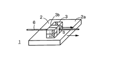
- 1 and 2 show an example in which the two magnetic poles of the magnet 3 are arranged in the normal direction of the one main surface 2a of the moving body 2, but the arrangement of the magnetic poles may be considered in addition to this. For example, FIG.
- FIG. 3A shows an example in which the two magnetic poles of the magnet 3 are arranged substantially parallel to one main surface 2 a of the moving body 2.
- 3B shows an example in which the two magnetic poles of the magnet 3 are arranged in a direction that is substantially parallel to one main surface 2a of the moving body 2 and that is different from the moving direction of the moving body 2.
- FIG. 3C shows an example in which four magnetic poles are provided on the magnet 3 and two magnetic poles having different polarities are arranged in the normal direction of the one principal surface 2a of the moving body 2.
- a fixing member 3b for fixing each magnetic pole is provided between two magnetic poles adjacent to each other in the principal surface direction.
- FIG. 3D shows an example in which the magnetic poles are arranged in a direction different from that of FIG.
- FIGS. 3A to 3D the magnetic flux from the magnet 3 passes on one main surface 2a of the moving body 2.
- FIG. Therefore, an eddy current can be generated on one main surface 2a as the moving body 2 moves, and the magnet 3 can be moved in the extending direction of the shaft member 6 by the reaction force of the eddy current. .
- the magnet 3 is movable along the shaft member 6 extending in the moving direction of the moving body 2, and the magnet 3 is disposed apart from the one main surface 2 a of the moving body 2.
- an eddy current can be generated on one main surface 2a of the moving body 2.
- the magnet 3 moves in the moving direction of the moving body 2 along the extending direction of the shaft member 6 by the repulsive force and the attractive force of the magnetic flux caused by the eddy current and the magnetic flux from the magnet 3.
- the magnet 3 can be moved in both directions in the extending direction of the shaft member 6 in a non-contact manner without using a power source.
- the induced electromotive force can be increased by increasing the amount of magnetic flux that passes through the main surface 2a and interlinks with the coil 4. Also, the induced electromotive force can be increased by increasing the magnetic force of the magnet 3.
- the moving body 2 can be mounted without a power source with a simple structure in which the magnet 3 that is movable in the extending direction of the shaft member 6 is disposed close to the one main surface 2a of the moving body 2. Since it can be moved in both directions along the shaft member 6, the moving body 2 can be moved in a non-contact manner at a place where an external power source cannot be taken.
- the moving body 2 only needs to move relative to the magnet 3, and the moving body 2 itself does not necessarily need to move. However, in order to generate the induced electromotive force in the coil 4, the moving body 2 needs to move in both directions with a certain period.
- the magnet 3 is vibrated in both directions while the moving body 2 moves in one direction.
- FIG. 4 is a front view of the non-contact generator 1 according to the second embodiment of the present invention.
- the magnet 3 that is spaced apart from one main surface 2 a of the moving body 2, the coil 4 in which the magnetic flux from the magnet 3 is linked, and the magnetic flux from the magnet 3 pass through.
- a yoke 5 a yoke 5.
- the main surface 2a of the moving body 2 has an uneven shape in which convex portions 2d and concave portions 2e are alternately arranged.
- the moving body 2 moves along the direction in which the convex portions 2d and the concave portions 2e are arranged.
- the moving body 2 may move not only in the direction of the arrow in FIG. 4 but also in the opposite direction.
- the moving body 2 according to the first embodiment cannot move the magnet 3 in both directions unless it moves in both directions.
- the moving body 2 is unidirectional. The magnet 3 can be moved in both directions even if it is moved only to.
- the magnet 3 is movable in both directions in the extending direction of the shaft member 6 as in the first embodiment, but a biasing member 7 made of a spring or the like is attached to the magnet 3.
- the biasing member 7 expands and contracts in the extending direction of the shaft member 6. For example, when the magnet 3 moves to the right side in FIG. 4, the biasing member 7 contracts, and the biasing member 7 has the magnet 3.
- the urging force that tries to move to the left side works. Conversely, when the magnet 3 moves to the left side of FIG. 4, the urging member 7 expands, and the urging force that moves the magnet 3 to the right side acts on the urging member 7.
- FIG. 4 shows an example in which only one urging member 7 is provided
- the urging members 7 may be provided on both sides of the magnet 3 in the shaft member 6.
- the biasing members 7 are provided on both sides of the magnet 3, when the magnet 3 moves in the moving direction of the moving body 2, one biasing member 7 expands and contracts and the other biasing member 7 expands.
- the urging member 7 is urged to return the magnet 3 to the original direction. Therefore, even if the urging force of each urging member 7 is weak, the magnet 3 can be returned to the original position, and each urging member 7 can be downsized.
- the magnet 3 can be moved based on the repulsive force and the attractive force (hereinafter referred to as the reactive force due to the eddy current) between the magnetic flux due to the eddy current and the magnetic flux from the magnet 3.
- the magnet 3 can also be moved based on the reluctance force acting between the magnetic flux from the magnet 3 and one main surface 2a of the moving body 2.
- the reluctance force is an attractive force that acts between the magnet 3 and a substance having high magnetic permeability.
- the following three can be considered as the principle of moving the magnet 3.
- the magnet 3 is moved using the reaction force caused by the eddy current without using the reluctance force.
- the magnet 3 is moved using the reluctance force without using the reaction force due to the eddy current.
- the magnet 3 is moved using both the reaction force caused by the eddy current and the reluctance force.
- the convex portion 2d on the one main surface 2a is closer to the magnet 3 than the concave portion 2e, and therefore the convex portion 2d has a reluctance force stronger than the concave portion 2e. . Therefore, when the moving body 2 moves in one direction with the convex portion 2d on the one main surface 2a and the magnet 3 facing each other, the magnet 3 follows the convex portion 2d so as to follow the convex portion 2d. Move in the direction of movement. At this time, since the magnet 3 contracts the urging member 7, the urging force to move the magnet 3 to the original position is accumulated in the urging member 7.
- the magnet 3 is moved in the direction opposite to the moving direction of the moving body 2 by the biasing member 7 due to the reluctance force between the magnet 3 and the convex portion 2d.
- the energizing force is working.
- the urging force gradually accumulates and increases, and the magnet 3 does not move in the moving direction of the moving body 2 at a position where the urging force and the reluctance force are balanced.
- the magnet 3 and the recess 2e are eventually disposed to face each other.
- the reluctance force is further weakened and the urging force is increased, so that the magnet 3 moves in the direction opposite to the moving direction of the moving body 2 by the urging force of the urging member 7.
- the magnet 3 is returned to the position where it is opposed to the convex portion 2d on the one main surface 2a of the next moving body 2 by the biasing force of the biasing member 7.
- the urging force in the direction opposite to the moving direction of the moving body 2 of the urging member 7 is weaker than the point in time when the urging force is balanced with the reluctance force in the moving direction of the moving body 2. Due to the reluctance force, the moving body 2 moves in the moving direction.
- the permeability of the one principal surface 2a In order to apply a reluctance force between the magnet 3 and the one principal surface 2a of the moving body 2, the permeability of the one principal surface 2a must be high.
- the one principal surface 2a is formed of a material having a low magnetic permeability such as aluminum, the reluctance force hardly acts.
- the permeability of the one main surface 2a of the moving body 2 is low and the conductivity is high.
- a material more specifically, a material having a permeability lower than the first threshold and a conductivity higher than the second threshold may be used.
- the material of the main surface 2a of the moving body 2 is high in permeability and low in conductivity. More specifically, the material may be formed of a material having a permeability higher than the first threshold and a conductivity lower than the second threshold.
- the main surface 2a of the moving body 2 is made of a material having both high permeability and conductivity, more specifically, The magnetic permeability and the conductivity may be made of a material higher than a predetermined threshold value.
- an attracting force attracting the convex portion 2d acts on the edge e1 side of the magnet 3, and a repulsive force repelling the convex portion 2d acts on the edge e2 side.
- the magnet 3 moves in the same direction as the moving body 2 at a slower speed than the moving body 2 so as to follow the moving body 2.
- the magnet 3 expands and contracts the biasing member 7, and the biasing force that tries to return the magnet 3 to the original position is accumulated in the biasing member 7.
- the magnet 3 Since there is a difference in moving speed between the moving body 2 and the magnet 3, the magnet 3 is eventually disposed opposite to the recess 2 e on the one main surface 2 a of the moving body 2.
- the distance from the main surface 2a of the magnet 3 is increased. Therefore, the eddy current formed on the concave portion 2e on the main surface 2a is also reduced, and the above-described attraction. Both power and repulsion are weakened. Therefore, the magnet 3 moves in the direction opposite to the moving direction of the moving body 2 by the biasing force of the biasing member 7.
- the magnet 3 is returned to the position where it is opposed to the convex portion 2d on the one main surface 2a of the next moving body 2 by the biasing force of the biasing member 7.
- the reaction force due to the eddy current becomes strong again, so that the magnet 3 moves in the moving direction of the moving body 2.
- the magnet 3 moves in the moving direction of the moving body 2 by using at least one of the reluctance force and the reaction force due to the eddy current even if the moving body 2 moves in only one direction. And vibrations going back and forth.
- a coil 4 in which the magnetic flux from the magnet 3 is linked and a yoke 5 through which the magnetic flux passes are arranged. Since the magnet 3 moves bidirectionally in the plane where the coil 4 is formed, the magnetic flux interlinking the coil 4 changes with time, and an induced electromotive force is generated in the coil 4.
- the magnet 3 since the magnet 3 can move only in the moving direction of the moving body 2, if the magnet 3 passes through the arrangement place of the coil 4, the coil 3 is not switched unless the moving direction of the moving body 2 is switched. No induced electromotive force can be generated at 4.
- the magnet 3 even if the moving body 2 is always moving in the same direction, the magnet 3 moves back and forth over the place where the coil 4 is arranged, so the moving direction of the moving body 2 is changed. Inductive electromotive force can be continuously generated by the coil 4. Therefore, practicality is improved as compared with the first embodiment.
- one main surface 2a of the moving body 2 has an uneven shape, but a specific example of the moving body 2 is a gear member having an uneven outer peripheral surface.
- the generated power can be used, for example, as power source power for a sensor that detects the number of rotations of the gear member. Therefore, it is not necessary to connect a power supply cable to the sensor, and for example, the speed of the gear member can be monitored without an external power source.
- the direction of the magnetic pole of the magnet 3 in FIG. 4 is an example, and the direction of the magnetic pole as shown in FIGS. 3A to 3D may be used.
- the size of the magnet 3 is the area of the convex portion 2d of the moving body 2. A size that fits within is desirable. Further, in order to obtain a necessary power generation amount, a plurality of non-contact generators having an optimal power generation amount may be connected.
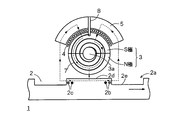
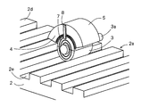
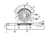
- FIG. 5 is a front view of a non-contact generator 1 according to a third embodiment of the present invention
- FIG. 6 is a perspective view.
- the magnet 3 that is spaced apart from one main surface 2 a of the moving body 2
- the coil 4 that links the magnetic flux from the magnet 3
- the magnetic flux from the magnet 3 pass through.
- a yoke 5 a yoke 5.
- convex portions 2d and concave portions 2e are alternately arranged on one main surface 2a of the movable body 2, and the movable body 2 moves in a direction in which the convex portions 2d and the concave portions 2e are arranged. .
- the third embodiment also rotates the magnet 3 by using at least one of a reaction force caused by an eddy current and a reluctance force.
- the magnet 5 has a hollow cylindrical shape, and a shaft member 3a is inserted through the hollow portion.
- the magnet 3 is rotatable together with the shaft member 3a around the shaft member 3a.
- a part of the outer peripheral surface of the magnet 3 is disposed opposite to the main surface 2 a of the moving body 2.
- the magnet 3 has, for example, two magnetic poles, and an N pole is disposed on the moving body 2 side relative to the shaft member 3a, and an S pole is disposed on the coil 4 side.
- the coil 4 is disposed to face a part of the outer peripheral surface of the magnet 3 so as to be spaced apart.
- the coil 4 is arranged at a uniform distance from the outer peripheral surface of the magnet 3. Therefore, the coil 4 is arrange
- a yoke 5 is disposed opposite to the surface of the coil 4 opposite to the surface facing the magnet 3.
- the cross section of the yoke 5 is formed in an arc shape according to the shapes of the magnet 3 and the coil 4.
- a biasing member 7 is attached to at least one end surface of the magnet 3 in the axial direction of the shaft member 3a.
- the urging member 7 is supported on the yoke 5 by a support member 8.
- Various modes of the specific structure of the urging member 7 and the attachment position to the magnet 3 can be considered, and any of them may be adopted.
- the urging member 7 When the magnet 3 rotates around the shaft member 3a, the urging member 7 accumulates an urging force in a direction opposite to the rotation direction.
- the magnet 3 is rotated by at least one of a reaction force caused by an eddy current and a reluctance force.
- the rotational force for rotating the magnet 3 becomes weaker than the biasing force, the magnet 3 rotates in the reverse direction by the biasing force.
- the magnet 3 When the magnet 3 is disposed opposite to the convex portion 2d on the one main surface 2a of the moving body 2, the magnet 3 is attracted to the convex portion 2d, so that when the moving body 2 moves in one direction, it follows the moving body 2.
- the magnet 3 rotates in the moving direction of the moving body 2, and the biasing force is accumulated in the biasing member 7 in the direction in which the magnet 3 is rotated in the reverse direction.
- the magnet 3 rotates counterclockwise.
- the magnets 3 are alternately disposed opposite to the convex portions 2d and the concave portions 2e, so that the above-described operation is repeated alternately, and the magnets 3 are arranged around the shaft member 3a. Rotate alternately in the direction. Thereby, the magnetic flux which links the coil 4 changes, and the induced electromotive force can be generated in the coil 4.
- the urging member 7 is rotated at a peripheral speed lower than the surface speed, and the urging force is exerted on the urging member 7 to return the magnet 3 to the original rotational position. Thereafter, when the magnet 3 is disposed opposite to the recess 2e on the one main surface 2a, the biasing force becomes larger than the reaction force due to the eddy current, and therefore the magnet 3 rotates in the reverse direction. Thereby, similarly to the rotation of the magnet 3 by the reluctance force, while the moving body 2 is moving in one direction, the magnet 3 performs an operation of alternately rotating around the shaft member 3a in both directions.
- the standard electric machine 9 is a drive body that is driven by utilizing the rotation of the shaft member 3a.
- the driving body includes, for example, a rotor (not shown) that rotates together with the shaft member 3a and a stator (not shown). The load is driven by the rotation of the rotor. More specifically, the drive body may be a generator, a speed reducer, or the like.
- the driving body may be a compressor that compresses air by using the rotational force of the shaft member 3a. As described above, the driving body includes not only one that converts the rotational force of the shaft member 3a into electric force but also one that converts the rotational force of the shaft member 3a into mechanical force.
- the non-contact generator 1 is also disposed near the outer peripheral surface of the movable body 2 made of a gear member, for example, a sensor that detects the rotational speed of the gear member. It can be used for the purpose of supplying power.
- the direction of the magnetic pole of the magnet 3 in FIG. 5 is an example, and the direction of the magnetic pole as shown in FIGS. 3A to 3D may be used.
- the size of the magnet 3 is the area of the convex portion 2d of the moving body 2. A size that fits within is desirable. Further, in order to obtain a necessary power generation amount, a plurality of non-contact generators having an optimal power generation amount may be connected.
- the cylindrical magnet 3 can be rotated and oscillated while alternately changing the rotation direction around the shaft member 3a only by moving the moving body 2 in one direction. Therefore, the magnetic flux interlinking with the coil 4 arranged to face the outer peripheral surface of the magnet 3 can be periodically changed, and the induction power can be efficiently generated in the coil 4.
- the coil 4 is disposed along the outer peripheral surface of the cylindrical magnet 3, and the magnet 3 rotates around the shaft member 3a without moving. Therefore, the non-contact generator 1
- the size in the left-right direction can be reduced as compared with the second embodiment. Therefore, according to the third embodiment, it is possible to provide the non-contact generator 1 that is space-saving and excellent in power generation efficiency.
- FIG. 8 shows an example in which the non-contact generator 1 having the same structure as FIG. 4 is disposed so as to oppose the flat main surface 2a of the moving body 2
- FIG. 9 shows the non-contact generator having the same structure as FIG. 1 shows an example in which 1 is placed close to and opposed to a flat main surface 2a of a moving body 2.
- the main surface 2a of the moving body 2 in FIGS. 8 and 9 is flat, but on the one main surface 2a, there are a first portion 2f and a second portion 2g having at least one of permeability and conductivity different from each other. Are alternately arranged, and the moving body 2 moves in the direction in which the first portion 2f and the second portion 2g are arranged.
- the first portion 2f and the second portion 2g of the moving body 2 need to have different magnetic permeability. For example, if the first portion 2f has a higher magnetic permeability than the second portion 2g, the magnet 3 moves or rotates in the moving direction of the moving body 2 when the first portion 2f is disposed opposite to the magnet 3. When the second portion 2g is disposed opposite to the magnet 3, the magnet 3 moves or rotates in the opposite direction by the biasing force of the biasing member 7.
- the first portion 2f and the second portion 2g of the moving body 2 need to have different conductivity. For example, assuming that the conductivity of the first portion 2f is higher than that of the second portion 2g, when the first portion 2f is disposed opposite to the magnet 3, the magnet 3 moves or rotates in the moving direction of the moving body 2. When the second portion 2g is disposed opposite to the magnet 3, the magnet 3 moves or rotates in the opposite direction by the biasing force of the biasing member 7.
- the magnet 3 can be moved or rotated in both directions.
- the magnet 3 is vibrated up and down.
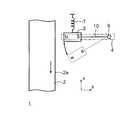
- FIG. 10 is a front view of the non-contact generator 1 according to the fifth embodiment of the present invention.
- the non-contact generator 1 of FIG. 10 includes a magnet 3 that is spaced apart from one main surface 2a extending in the first direction x of the moving body 2 that moves in the first direction x, and the magnet 3 in the first direction. a biasing member 7 for biasing in the direction x or the opposite direction; a shaft member 6 of the magnet 3 that is spaced apart from the magnet 3 and extends in a second direction y that intersects the first direction x; the magnet 3 and the shaft A connection member 10 connected to the member 6 and rotating the magnet 3 around the shaft member 6 and a coil 4 in which the magnetic flux of the magnet 3 is linked are provided.
- the first direction x is, for example, the vertical direction
- the second direction y is, for example, the horizontal direction.
- the moving body 2 moves downward, for example, in the vertical direction, that is, in the direction of gravity.
- the moving body 2 may move in the direction opposite to the gravity direction (upward), or in both directions of the gravity direction and the opposite direction.
- the magnet 3 is connected to the shaft member 6 by the connecting member 10, and the magnet 3 is rotatable around the shaft member 6.
- the magnet 3 In the initial state, the magnet 3 is supported by the urging member 7 and the connecting member 10 and is stopped at a predetermined position. At this stop position, one magnetic pole end surface of the magnet 3 is disposed opposite to one main surface 2 a of the moving body 2.
- the magnet 3 stops stably.
- the coil 4 is disposed at a place where the magnetic flux from the magnet 3 is linked. For example, you may arrange
- the moving body 2 moves in one direction (for example, downward in the direction of gravity) from the initial state, an eddy current is generated on one main surface 2a of the moving body 2, and the reaction force caused by the eddy current causes the magnet 3 to The moving body 2 moves in the moving direction.
- the magnet 3 also moves downward.
- the urging member 7 accumulates an urging force for returning the magnet 3 to the original balance position.
- the connecting member 10 is connected to the magnet 3 in addition to the urging member 7, as shown by a broken line in FIG. 10, one magnetic pole end surface of the magnet 3 and one main surface 2 a of the moving body 2 The distance becomes larger. Thereby, the urging force of the urging member 7 becomes larger than the reaction force due to the eddy current, and the magnet 3 moves in the direction (for example, upward) opposite to the moving direction of the moving body 2.
- the magnet 3 moves upward, the distance between the one magnetic pole end surface of the magnet 3 and the one main surface 2a of the moving body 2 is shortened, and an urging force for moving the magnet 3 downward accumulates in the urging member 7. Therefore, the magnet 3 moves downward again. By repeating the above operation, even when the moving body 2 moves in one direction, the magnet 3 performs a vibrating operation that alternately moves in one direction and the opposite direction.
- the magnetic flux interlinking the coil 4 periodically changes in accordance with the vibration period of the magnet 3, and an induced electromotive force is generated in the coil 4.
- the magnet 3 is spaced from the main surface 2a of the moving body 2 so as to face the magnet 3, and the magnet 3 is urged by the urging member 7, and the magnet 3 is connected to the connecting member 10.
- the magnet 3 can be vibrated in one direction and in the opposite direction even if the moving body 2 moves in one direction by making the shaft member 6 rotatable through the.
- the magnet 3 in the first to fifth embodiments described above may be a permanent magnet or an electromagnet. Further, the shapes of the magnet 3 and the yoke 5 are not limited to those illustrated. Further, the yoke 5 may be omitted depending on circumstances.
- Non-contact generator 2 moving body, 3 magnet, 4 coil, 5 yoke, 6 shaft member, 7 Biasing member, 8 support member, 9 standard electric machine, 10 connecting member
Landscapes
- Engineering & Computer Science (AREA)
- Power Engineering (AREA)
- Linear Motors (AREA)
- Dynamo-Electric Clutches, Dynamo-Electric Brakes (AREA)
- Reciprocating, Oscillating Or Vibrating Motors (AREA)
- Connection Of Motors, Electrical Generators, Mechanical Devices, And The Like (AREA)
Abstract
Le problème décrit par l'invention est de produire un générateur de puissance sans contact qui a une bonne efficacité magnétique et une faible fuite de flux magnétique. La solution selon l'invention porte sur un générateur de puissance sans contact 1 pourvu : d'un aimant 3 qui est disposé opposé et espacé d'une surface principale d'un corps mobile qui se déplace dans une première direction et dans la direction opposée à ladite première direction, l'aimant pouvant se déplacer le long de l'axe s'étendant dans la direction de déplacement du corps mobile, et produisant un flux magnétique qui traverse la surface principale ; d'une bobine 4 qui est disposée espacée d'une surface sur le côté opposé à une surface faisant face à une surface principale de l'aimant, et interconnectée au flux magnétique de l'aimant ; et d'un élément de guidage de flux magnétique 5 qui est disposé dans une partie d'un trajet magnétique à travers lequel passe le flux magnétique en interconnexion avec la bobine. À l'aide d'une force de réaction agissant sur l'aimant sur la base d'un courant de Foucault produit dans une direction empêchant un changement du flux magnétique de l'aimant sur la première surface principale du corps mobile, l'aimant 3 se déplace le long d'un axe dans la direction de déplacement du corps mobile à une vitesse qui est inférieure à la vitesse de déplacement du corps mobile.
Priority Applications (4)
| Application Number | Priority Date | Filing Date | Title |
|---|---|---|---|
| EP20202572.2A EP3799278A3 (fr) | 2015-06-10 | 2016-06-09 | Générateur de puissance sans contact |
| CN201680047205.2A CN107925335B (zh) | 2015-06-10 | 2016-06-09 | 非接触发电机 |
| EP16807554.7A EP3309942B1 (fr) | 2015-06-10 | 2016-06-09 | Générateur de puissance sans contact |
| US15/834,663 US10298107B2 (en) | 2015-06-10 | 2017-12-07 | Non-contact power generator |
Applications Claiming Priority (2)
| Application Number | Priority Date | Filing Date | Title |
|---|---|---|---|
| JP2015117771A JP6567331B2 (ja) | 2015-06-10 | 2015-06-10 | 非接触発電機 |
| JP2015-117771 | 2015-06-10 |
Related Child Applications (1)
| Application Number | Title | Priority Date | Filing Date |
|---|---|---|---|
| US15/834,663 Continuation US10298107B2 (en) | 2015-06-10 | 2017-12-07 | Non-contact power generator |
Publications (1)
| Publication Number | Publication Date |
|---|---|
| WO2016199848A1 true WO2016199848A1 (fr) | 2016-12-15 |
Family
ID=57503415
Family Applications (1)
| Application Number | Title | Priority Date | Filing Date |
|---|---|---|---|
| PCT/JP2016/067205 Ceased WO2016199848A1 (fr) | 2015-06-10 | 2016-06-09 | Générateur de puissance sans contact |
Country Status (5)
| Country | Link |
|---|---|
| US (1) | US10298107B2 (fr) |
| EP (2) | EP3309942B1 (fr) |
| JP (1) | JP6567331B2 (fr) |
| CN (1) | CN107925335B (fr) |
| WO (1) | WO2016199848A1 (fr) |
Families Citing this family (3)
| Publication number | Priority date | Publication date | Assignee | Title |
|---|---|---|---|---|
| CN106877617A (zh) * | 2017-04-12 | 2017-06-20 | 成都步共享科技有限公司 | 一种用于共享单车的发电装置 |
| DE102018217002A1 (de) * | 2018-10-04 | 2020-04-09 | Zf Friedrichshafen Ag | System zur Energiegewinnung sowie Verfahren zum Betreiben eines Systems zur Energiegewinnung |
| CN113465684B (zh) * | 2021-08-03 | 2025-05-23 | 上海交通大学 | 非接触式运动体状态检测装置 |
Citations (1)
| Publication number | Priority date | Publication date | Assignee | Title |
|---|---|---|---|---|
| JP2000134905A (ja) * | 1998-10-26 | 2000-05-12 | Seiko Epson Corp | 走行体の制動装置 |
Family Cites Families (14)
| Publication number | Priority date | Publication date | Assignee | Title |
|---|---|---|---|---|
| JPS5967864A (ja) * | 1982-10-12 | 1984-04-17 | Oki Electric Ind Co Ltd | 直流ブラシレスリニアモ−タ |
| US5347186A (en) * | 1992-05-26 | 1994-09-13 | Mcq Associates, Inc. | Linear motion electric power generator |
| CN1067815C (zh) * | 1996-11-13 | 2001-06-27 | 荻野三四郎 | 利用永磁铁的能量转换装置 |
| WO2001033700A1 (fr) * | 1999-11-02 | 2001-05-10 | Relight | Dispositif de production d'electricite pour vehicule |
| DE102009054599A1 (de) * | 2009-07-29 | 2011-02-03 | Robert Bosch Gmbh | Reluktanzmotor |
| GB2479926B (en) * | 2010-04-30 | 2016-05-11 | Atherton Nigel | Electricity generator |
| US8299659B1 (en) * | 2010-08-14 | 2012-10-30 | Bartol Jr Robert J | Electric power generator apparatus |
| US8604649B1 (en) * | 2010-08-14 | 2013-12-10 | Robert J. Bartol, Jr. | Electric generator and related methods |
| US8901783B2 (en) * | 2010-08-24 | 2014-12-02 | Qualcomm Incorporated | Handheld device force induction |
| DE202011107060U1 (de) | 2011-07-01 | 2012-10-09 | Dirk Strothmann | Vorrichtung zur berührungslosen Stromerzeugung, insbesondere Fahrraddynamo, Fahrzeugbeleuchtungsanlage und Fahrrad |
| US9347332B2 (en) * | 2011-07-28 | 2016-05-24 | Mitsui Engineering & Shipbuilding | Dynamo with columnar oscillator |
| US8816541B1 (en) * | 2011-09-30 | 2014-08-26 | Theodore R. Bristow | Electricity generating apparatus |
| JP5785886B2 (ja) * | 2012-02-27 | 2015-09-30 | アズビル株式会社 | 磁気バネ装置 |
| EP2703264A1 (fr) * | 2012-08-28 | 2014-03-05 | Reelight APS | Générateur de courant de Foucault pour bicyclettes |
-
2015
- 2015-06-10 JP JP2015117771A patent/JP6567331B2/ja active Active
-
2016
- 2016-06-09 EP EP16807554.7A patent/EP3309942B1/fr active Active
- 2016-06-09 EP EP20202572.2A patent/EP3799278A3/fr active Pending
- 2016-06-09 CN CN201680047205.2A patent/CN107925335B/zh active Active
- 2016-06-09 WO PCT/JP2016/067205 patent/WO2016199848A1/fr not_active Ceased
-
2017
- 2017-12-07 US US15/834,663 patent/US10298107B2/en active Active
Patent Citations (1)
| Publication number | Priority date | Publication date | Assignee | Title |
|---|---|---|---|---|
| JP2000134905A (ja) * | 1998-10-26 | 2000-05-12 | Seiko Epson Corp | 走行体の制動装置 |
Also Published As
| Publication number | Publication date |
|---|---|
| EP3309942A1 (fr) | 2018-04-18 |
| JP2017005877A (ja) | 2017-01-05 |
| US20180159414A1 (en) | 2018-06-07 |
| CN107925335A (zh) | 2018-04-17 |
| EP3309942B1 (fr) | 2020-11-18 |
| JP6567331B2 (ja) | 2019-08-28 |
| EP3799278A2 (fr) | 2021-03-31 |
| EP3309942A4 (fr) | 2019-06-26 |
| EP3799278A3 (fr) | 2021-08-18 |
| CN107925335B (zh) | 2020-08-04 |
| US10298107B2 (en) | 2019-05-21 |
Similar Documents
| Publication | Publication Date | Title |
|---|---|---|
| US10463460B2 (en) | Personal cleaning care appliance | |
| JP6850832B2 (ja) | リニア振動モータ | |
| JP6639810B2 (ja) | 回転電機および非接触発電機 | |
| JP5224209B2 (ja) | 二次元共鳴振動モーター | |
| EP3157462B1 (fr) | Système d'entraînement pour appareil de soins d'hygiène personnelle | |
| WO2016199845A1 (fr) | Machine électrique tournante et générateur électrique sans contact | |
| JP6567331B2 (ja) | 非接触発電機 | |
| US20130229080A1 (en) | Rotary Continuous Permanent Magnet Motor | |
| JP5372115B2 (ja) | 回転電機 | |
| KR101094651B1 (ko) | 감각신호출력장치 | |
| KR102393595B1 (ko) | 선형 동력발생장치 | |
| KR101069953B1 (ko) | 회전속도에 따른 유동식 회전판을 갖는 전동장치 | |
| WO2016199861A1 (fr) | Machine électrique rotative et générateur de puissance sans contact | |
| WO2010083538A2 (fr) | Générateurs et moteurs utilisant un champ magnétique propagé | |
| JP5481456B2 (ja) | 回転電機 | |
| WO2016199844A1 (fr) | Machine électrique rotative | |
| JP2010226911A (ja) | 高効率発電及び動力装置。 | |
| JP2015181966A (ja) | 振動生成装置、及びロボット | |
| JP2014188480A (ja) | 振動生成装置、およびロボット | |
| JP2019075919A (ja) | 振動発電機 |
Legal Events
| Date | Code | Title | Description |
|---|---|---|---|
| 121 | Ep: the epo has been informed by wipo that ep was designated in this application |
Ref document number: 16807554 Country of ref document: EP Kind code of ref document: A1 |
|
| NENP | Non-entry into the national phase |
Ref country code: DE |
|
| WWE | Wipo information: entry into national phase |
Ref document number: 2016807554 Country of ref document: EP |