WO2016199925A1 - Dispositif intra-oral imprimant des vibrations - Google Patents
Dispositif intra-oral imprimant des vibrations Download PDFInfo
- Publication number
- WO2016199925A1 WO2016199925A1 PCT/JP2016/067452 JP2016067452W WO2016199925A1 WO 2016199925 A1 WO2016199925 A1 WO 2016199925A1 JP 2016067452 W JP2016067452 W JP 2016067452W WO 2016199925 A1 WO2016199925 A1 WO 2016199925A1
- Authority
- WO
- WIPO (PCT)
- Prior art keywords
- dentition
- vibration
- contact portion
- intraoral
- user
- Prior art date
- Legal status (The legal status is an assumption and is not a legal conclusion. Google has not performed a legal analysis and makes no representation as to the accuracy of the status listed.)
- Ceased
Links
Images

Classifications
-
- A—HUMAN NECESSITIES
- A61—MEDICAL OR VETERINARY SCIENCE; HYGIENE
- A61C—DENTISTRY; APPARATUS OR METHODS FOR ORAL OR DENTAL HYGIENE
- A61C7/00—Orthodontics, i.e. obtaining or maintaining the desired position of teeth, e.g. by straightening, evening, regulating, separating, or by correcting malocclusions
- A61C7/08—Mouthpiece-type retainers or positioners, e.g. for both the lower and upper arch
Definitions
- the present invention relates to an intraoral vibration imparting device that improves the environment in the oral cavity by imparting ultrasonic vibrations to the oral cavity.
- a dental vibration imparting device that imparts vibration to a bracket or a wire that is an orthodontic device (for example, see Patent Document 1).
- the dental vibration imparting device of Patent Document 1 imparts vibration generated by rotating an eccentric motor to one of the brackets attached to the wire in order to impart vibration to specific teeth in the dentition. ing. Thereby, the correction of the dentition fixed by the bracket and the wire is promoted.
- the present invention has been made in view of the above-described points, and an object of the present invention is to provide an intraoral vibration imparting apparatus that can be used for a wide range of uses related to improvement of the intraoral environment.
- the intraoral vibration imparting device (1) of the present invention for solving the above-described problems includes a dental contact portion (60) for direct contact with a user's dental row (T), and a dental contact portion (60).
- the vibration generating unit (31) drives the vibrator (11) to generate ultrasonic vibration in the dentition contact unit (60). After the user contacts the dentition (T) by sandwiching the dentition contact portion (60) between the upper teeth (TU) and the lower teeth (TD), the user operates the operation portion (31). When the ultrasonic vibration propagates throughout the oral cavity through the dentition (T) by transmitting the electrical signal from the vibration generating unit (31) to the vibrator (11), the dentition (T) is corrected. Can be promoted.
- ultrasonic vibration spreads through the dentition (T) to every corner of the oral cavity, so that it accumulates not only in the dirt and plaque adhering to the tooth surface, but also in the tooth groove and the gap between the teeth and gums. It is possible to effectively remove the soiled dirt and to effectively decompose bacteria present in the oral cavity.
- bacteria such as cavities and periodontal diseases (mutans) are broken down by the ultrasonic vibration that propagates through the dentition in the oral cavity. It is very effective for removal (sterilization) of water.
- the dentition contact portion (60) is integrally formed with the vibrator (11), and is formed of a horseshoe-shaped plate and formed of a hard member (61). And a dentition contact portion (including a vibration transmission plate (61)) that is formed by a horseshoe-shaped plate-like soft member and contacts the lower surface of the user's upper teeth (TU) and the upper surface of the lower teeth (TD) ( 62).
- the vibration transmission plate (61) integrated with the vibrator (11) is a horseshoe-shaped hard plate, the vibration of the vibrator (11) is more widely and efficiently transmitted.
- the dentition abutting portion (62) is soft and easily deforms following the surface shape of the dentition (T), so that it is formed on the lower surface of the user's upper teeth (TU) and the upper surface of the lower teeth (TD). It makes contact with each other securely.
- the vibration transmission plate (61) that easily transmits the vibration of the vibrator (11) and the tooth row contact portion (62) that reliably contacts the surface shape of the tooth row (T) thus, the vibration of the vibrator (11) is effectively propagated to the dentition (T).
- the upper teeth (TU) and lower teeth (TD) of the user extended to the dentition contact portion (60) above and below the dentition contact portion (62). It is good also as a structure which has a dentition contact wall (65) contact
- the dentition contact portion (60) may be exchangeable. If the dentition contact portion (60) is configured to be replaceable, the dentition (T) has individual differences depending on the user, so the dentition made in accordance with the shape and application of the user's dentition (T). The contact part (60) can be exchanged. Thereby, the vibration of the vibrator (11) is more efficiently and reliably transmitted to the dentition (T) of a specific user.
- the intraoral vibration applying device (1) includes a controller unit (30) connected to the dentition contact unit (60) by wiring, and includes a vibration generating unit (31), a control means (33), and a power supply unit. (35) and the operation unit (37) may be provided in the controller unit (30).
- the dentition contact part (60) and the controller part (30) are separated, so that the dentition contact part (60) and the controller part (30) are integrated,
- the dentition contact portion (60) can be reduced in size and weight.
- the operability of the intraoral vibration applying device (1) is improved.
- symbol in said parenthesis has shown the code
- an intraoral vibration imparting apparatus that can be used for a wide range of applications related to the improvement of the intraoral environment can be provided.
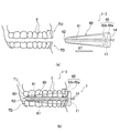
- FIG. 1 It is a figure which shows the intraoral vibration provision apparatus which concerns on 1st Embodiment, (a) is a perspective view which shows the whole structure, (b) is the elements on larger scale which show the structure of a dentition contact part. It is a figure which shows the use condition of the intraoral vibration provision apparatus which concerns on 1st Embodiment, (a) is a side view before mounting
- FIG. 1 It is a figure which shows the structure and use condition of the intraoral vibration provision apparatus which concerns on 3rd Embodiment, (a) is a side view before mounting
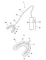
- FIG. 1 is a perspective view showing the overall configuration of the intraoral vibration applying device 1 according to the first embodiment.
- 2A and 2B are diagrams showing a use state of the intraoral vibration imparting apparatus 1 according to the first embodiment, wherein FIG. 2A is a side view before wearing, and FIG. 2B is a side view when wearing.
- the intraoral vibration imparting device 1 shown in FIG. 1 includes a plate-like tooth contact portion 60 formed in a horseshoe shape (U-shape) for direct contact with a user's tooth row T, a tooth contact portion 60, and an electric cable. 14 (wiring) and an electric cable (wiring) 15.
- the electrical cable 14 is configured integrally with the dentition contact portion 60
- the electrical cable 15 is configured integrally with the controller unit 30.
- a jack portion 16 that enables connection and separation between the electric cable 14 and the electric cable 15 is provided at a portion where the electric cable 14 and the electric cable 15 are connected. Since the electric cable 14 attached to the dentition contact portion 60 in the jack portion 16 is separated from the electric cable 15, when a plurality of types of dentition contact portions 60 having different shapes are used, the jack portion 16 must be separated and connected. Thus, the dentition contact portion 60 can be replaced.
- the dentition contact portion 60 incorporates a vibrator 11 (oscillation element) that vibrates the dentition contact portion 60.
- the vibrator 11 is disposed integrally with a vibration transmission plate 61 disposed in the dentition contact portion 60.
- the vibrator 11 causes vibration by ultrasonic waves based on the electric signal transmitted from the vibration generating unit 31 to vibrate the dentition contact unit 60.
- the dentition contact portion 60 includes a vibration transmission plate 61 integrally formed with the vibrator 11, and includes the vibration transmission plate 61, and is formed with respect to the lower surface of the user's upper teeth TU and the upper surface of the lower teeth TD. It has a tooth row contact portion 62 that makes contact, and a heating wire 67 embedded in the tooth row contact portion 62.
- the vibration transmission plate 61 and the tooth row contact portion 62 are each formed in a substantially U-shaped horseshoe shape so as to correspond to the entire region of the tooth row T (see FIG. 1).
- the vibration transmission plate 61 has a horseshoe shape as described above, and is connected so as to be integrated with the vibrator 11 so that vibration of the vibrator 11 directly propagates.
- the vibration transmission plate 61 is made of ceramic or other ceramics, or a hard member such as metal or hard resin, and is formed in a thin plate shape in order to reliably propagate vibrations without unevenness. Further, the vibration transmission plate 61 is disposed in the entire region inside the tooth contact portion 60 in order to efficiently propagate the vibration to all the tooth rows T.
- the tooth row contact portion 62 has a horseshoe shape as described above, and is configured to cover the entire outside of the vibration transmission plate 61.
- the dentition contact portion 62 is made of a soft resin or the like so that a sense of incongruity can be reduced when the user's dentition T comes into contact (when the user holds the dentition contact portion 62). Consists of members.
- Both ends of the heating wire 67 embedded in the dentition contact portion 62 are connected to the wiring in the electric cable 14 and are electrically connected to the thermal control unit 32 on the electric circuit board 40 described later. . Accordingly, the heating wire 67 generates heat when electricity supplied via the wiring in the electric cable 14 is energized. The heat generation propagates to the entire dentition contact portion 60 through the dentition contact portion 62, so that the dentition contact portion can have a thermal effect.
- the dentition contact portion 60 is configured as described above, when the user inserts the dentition contact portion 60 into the oral cavity, first, the mouth is opened to the extent that the vertical width of the dentition contact portion 60 is included. After that, as shown in FIG. 2A, the dentition contact portion 60 is inserted into the mouth in the direction of the arrow. Next, the dentition contact portion 60 is sandwiched between the user's upper teeth TU and lower teeth TD. Thereby, the dentition contact portion 60 is fixed in the oral cavity of the user.
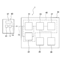
- FIG. 3 is a block diagram showing the configuration of the intraoral vibration applying device.
- the controller unit 30 causes the vibration generating unit (ultrasonic transmitter) 31 that generates an electrical signal for causing the vibrator 11 to generate vibrations by ultrasonic waves, and the heating wire 67 to generate heat.
- a control circuit (control means) 33 for controlling the vibration generating unit 31 and the thermal control unit 32, and for driving the vibration generating unit 31, the thermal control unit 32 and the control circuit 33.
- a battery (power supply unit) 35 for supplying power, an operation switch (operation unit) 37 operated by a user, and display means 39 having a display lamp and the like are provided.
- the vibration generating unit 31 of the controller unit 30 generates an electrical signal for causing the vibrator 11 of the dentition contact unit 60 to generate ultrasonic vibration (hereinafter referred to as “ultrasonic vibration”). Further, the thermal control unit 32 generates a current for causing the heating wire 67 to generate heat.
- the battery 35 supplies power for driving the vibration generating unit 31 and the thermal control unit 32.
- the vibrator 11 and the heating wire 67 of the dentition contact unit 60 are electrically connected to the vibration generating unit 31 of the controller unit 30 via the electric cable 14 and the electric cable 15.
- the control circuit 33 controls the generation of ultrasonic vibrations by the vibration generating unit 31 and the heat generation of the heating wire 67 by the thermal control unit 32. Control of ultrasonic vibration is performed by inputting an ultrasonic voltage signal from the vibration generating unit 31 to the vibrator 11 that is a piezoelectric element.
- the control circuit 33 controls the entire intraoral vibration applying device 1 in addition to the control of the vibration generating unit 31 and the thermal control unit 32.
- the control circuit 33 may be provided with a timer circuit for controlling the ultrasonic wave transmission time by the vibration generator 31 and the heat generation time of the heating wire 67.
- the vibration generator 31, the thermal controller 32, the control circuit 33, and the operation switch 37 are mounted on the electric circuit board 40.
- the electric circuit board 40 is electrically connected to the battery 35 and is driven by electric power supplied from the battery 35.
- the battery 35 as the power supply unit can use a dry battery, a storage battery, or the like as an example, but is not limited thereto, as long as it can secure a power supply for the vibration generating unit 31, the thermal control unit 32, and the control circuit 33. Other configurations may be used.
- the vibration generating unit 37 drives the vibrator 11 to generate ultrasonic vibration in the dentition contact unit 60.
- the user After the user contacts the dentition T by sandwiching the dentition contact portion 60 between the upper teeth TU and the lower teeth TD, the user operates the operation portion 31 to generate an electrical signal from the vibration generation portion 31.
- the vibration generation portion 31 By transmitting to the vibrator 11, if ultrasonic vibration propagates throughout the oral cavity via the dentition T, correction of the dentition T can be promoted.
- the intraoral vibration imparting apparatus 1 of this embodiment when using it for orthodontics, if the intraoral vibration imparting apparatus 1 of this embodiment is used in a state where orthodontic tools such as a bracket and a wire are attached to the dentition T, it is more effective in a shorter time. Correction to a desired dentition can be realized.
- the audible range vibration is transmitted to the teeth, and the environment in the oral cavity is compared with the case of having only an orthodontic promotion effect. More actions for improvement can be imparted.
- the vibration which can be utilized for the wide use which concerns on improvement of intraoral environment can be provided.
- the intraoral vibration imparting apparatus 1 of the present embodiment is configured to impart a thermal effect to the dentition contact portion 60 by a heating wire 67 embedded in the dentition contact portion 62 of the dentition contact portion 60. .
- the user of the intraoral vibration imparting device 1 feels the comfort due to the warm feeling, and in addition, the usability can be improved and the orthodontic can be effectively performed in a shorter time due to the thermal effect. There is also an effect.
- the dentition contact part 60 of the intraoral vibration applying device 1 of the present embodiment includes a vibration transmission plate 61 and a dentition contact part 62.
- the vibration transmission plate 61 integrated with the vibrator 11 is a horseshoe-shaped hard plate, the vibration of the vibrator 11 is more widely and efficiently transmitted.
- the dentition abutting portion 62 is soft and easily deforms following the surface shape of the dentition T, so that the dentition abutment portion 62 reliably contacts the lower surface of the user's upper teeth TU and the upper surface of the lower teeth TD.
- the vibration transmission plate 61 that easily transmits the vibration of the vibrator 11 and the tooth row abutment portion 62 that reliably comes into contact with the surface shape of the tooth row T, the vibration of the vibrator 11 can be further reduced. It will propagate effectively to the column T.
- the intraoral vibration applying device 1 of the present embodiment is configured so that the electrical cable 14 and the electrical cable 15 can be separated and connected again in the jack portion 16 and the dentition contact portion 60 can be replaced. Yes. If the dentition contact portion 60 is configured to be replaceable, the dentition T has individual differences depending on the user. Therefore, the dentition contact portion 60 is replaced with a dentition contact portion 60 made in accordance with the shape and application of the user's dentition T. You can also do that. Thereby, the vibration of the vibrator 11 is more efficiently and reliably propagated to the dentition T of a specific user.
- the dentition contact part 60 and the controller part 30 are separated. Thereby, compared with what integrated the dentition contact part 60 and the controller part 30, the size reduction and weight reduction of the dentition contact part 60 can be achieved. Further, in a state where the small and light dentition contact part 60 is sandwiched between the dentitions T, the dentition contact part 60 can be operated by using the controller part 30 outside the oral cavity, and the user visually recognizes the operation part 37 of the controller part 30 Therefore, the operability of the intraoral vibration imparting device 1 is improved.
- FIGS. 4A and 4B are diagrams showing a configuration and a usage state of the intraoral vibration imparting device 1-2 according to the second embodiment.
- FIG. 4A is a side view before wearing
- FIG. 4B is a side view when wearing. is there.
- the same components as those in the first embodiment are denoted by the same reference numerals, and the description thereof is omitted.
- the shapes of the user's upper teeth TU and lower teeth TD are formed on the surface of the dentition contact portion 62 of the dentition contact portion 60 provided in the intraoral vibration applying device 1-2 of this embodiment.
- An uneven shape 63 corresponding to is formed on the surface of the dentition contact portion 62 of the dentition contact portion 60 provided in the intraoral vibration applying device 1-2 of this embodiment.
- the soft member and the concavo-convex shape 63 ensure that the maxillary tooth TU and the mandibular tooth TD abut against the dentition abutment portion 62.
- corrugated shape 63 is formed in the position corresponding to the maxillary tooth TU and the mandibular tooth TD, it is not restricted to this.
- the position of the concavo-convex shape 63 can be formed slightly shifted from the actual positions of the maxillary tooth TU and the mandibular tooth TD. By vibrating with this configuration, the tooth row T can be guided to a more preferable position.
- the mouth is opened to such an extent that the vertical width of the dentition contact portion 60 enters, and then, as shown in FIG. As shown, the dentition contact portion 60 is inserted into the mouth in the direction of the arrow.
- the dentition contact part 60 is clamped by the user's upper teeth TU and lower teeth TD. Thereby, the dentition contact portion 60 is fixed in the oral cavity of the user.
- the upper jaw teeth TU and the lower jaw teeth TD of the user hold the teeth so as to match the concave and convex shapes 63 formed above and below the tooth row contact portion 62 of the tooth row contact portion 60.
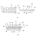
- FIG. 5 is a perspective view showing the configuration of the dentition contact portion 60 of the intraoral vibration applying apparatus 1-3 according to the third embodiment.
- the dentition contact portion 60 of the intraoral vibration imparting device 1-3 of the present embodiment has a vibrator 11 (oscillation element) that vibrates the dentition contact portion 60, as in the first embodiment. Is built in, and the vibrator 11 causes vibration by ultrasonic waves based on the electrical signal transmitted from the vibration generating unit 31 to vibrate the dentition contact unit 60.
- the dentition contact portion 60 of the present embodiment further includes a dentition contact wall 65 that extends above and below the dentition contact portion 62 and contacts the inner and outer surfaces of the user's upper teeth TU and lower teeth TD.
- the tooth row abutting wall 65 includes an outer wall 65 a that abuts on the outer surface of the tooth row T, and an inner wall 65 b that abuts on the inner side surface of the tooth row T.
- the heating wire 67 of the dentition contact portion 60 is omitted.
- the dentition contact wall 65 of this embodiment is configured to include both the outer wall 65a and the inner wall 65b, the present invention is not limited to this, and the dentition contact wall 65 may be the outer wall 65a or the inner wall. Only one of 65b may be used. Further, in order to more reliably contact the dentition contact portion 60 and the dentition T to the side surface of the dentition contact wall 65, an uneven shape corresponding to the surface shape of the dentition T may be formed. .
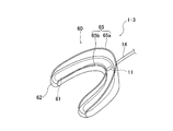
- FIG. 6A and 6B are diagrams showing a use state of the intraoral vibration imparting apparatus 1-3 according to the third embodiment, in which FIG. 6A is a side view before wearing, and FIG. 6B is a side view when wearing.
- the dentition contact part 60 of the present embodiment is configured as described above, when the user inserts the dentition contact part 60 into the oral cavity, first, the vertical width (dentition of the dentition contact part 60) 6), the dentition contact portion 60 is inserted into the mouth in the direction of the arrow, as shown in FIG. 6 (a). To do.
- the user's maxillary teeth so that the outer wall 65a of the dentition contact wall 65 contacts the outer side of the dentition T and the inner wall 65b of the dentition contact wall 65 contacts the inner side of the dentition T.
- the dentition contact portion 60 is sandwiched between the TU and the lower jaw tooth TD. Further, when the uneven shape 63 is formed above and below the dentition contact portion 62, the concavo-convex shape 63 is made to match the position of the corresponding tooth row T. By these, the dentition contact part 60 is fixed in a user's oral cavity.
- the dentition contact portion 60 of the intraoral vibration imparting device 1-3 With the above configuration, according to the configuration of the dentition contact portion 60 of the intraoral vibration imparting device 1-3 according to the present embodiment, not only the dentition contact portion 62 but also the dentition contact portion 62 extends vertically. Since the dentition contact wall 65 is in contact with the inner surface or the outer surface of the dentition T, the dentition contact portion 60 is more reliably fixed to the dentition T. Propagation to the dentition T more reliably.
Landscapes
- Health & Medical Sciences (AREA)
- Oral & Maxillofacial Surgery (AREA)
- Dentistry (AREA)
- Epidemiology (AREA)
- Life Sciences & Earth Sciences (AREA)
- Animal Behavior & Ethology (AREA)
- General Health & Medical Sciences (AREA)
- Public Health (AREA)
- Veterinary Medicine (AREA)
- Dental Tools And Instruments Or Auxiliary Dental Instruments (AREA)
Abstract
L'invention concerne un dispositif intra-oral (1) imprimant des vibrations et comportant : une partie de contact (60) avec des rangées de dents, destinée à être mise en contact direct avec des rangées de dents (T) d'un utilisateur ; un vibrateur (11) qui met en vibration la partie de contact (60) avec des rangées de dents ; une partie de génération de vibrations (31) qui génère un signal électrique provoquant la génération de vibrations ultrasonores par le vibrateur (11) ; un fil électrique chauffant (67) servant à appliquer de la chaleur à la partie de contact (60) avec des rangées de dents ; une partie commande de chauffage (32) qui génère un courant électrique provoquant l'émission de chaleur par le fil électrique chauffant (67) ; un moyen de commande (33) servant à commander la partie génération de vibrations (31) et la partie commande de chauffage (32) ; une unité d'alimentation électrique (35) qui délivre l'énergie pour l'entrainement de la partie génération de vibrations (31), la partie commande de chauffage (32) et le moyen de commande (33) ; et une partie fonctionnelle (37) qui est actionnée par un utilisateur. La configuration est telle que les vibrations ultrasonores provenant de la partie de contact (60) avec des rangées de dents se propagent dans la cavité buccale par l'intermédiaire des rangées de dents (T).
Priority Applications (1)
| Application Number | Priority Date | Filing Date | Title |
|---|---|---|---|
| JP2017523735A JP6375448B2 (ja) | 2015-06-10 | 2016-06-10 | 口腔内振動付与装置 |
Applications Claiming Priority (2)
| Application Number | Priority Date | Filing Date | Title |
|---|---|---|---|
| JP2015117784 | 2015-06-10 | ||
| JP2015-117784 | 2015-06-10 |
Publications (1)
| Publication Number | Publication Date |
|---|---|
| WO2016199925A1 true WO2016199925A1 (fr) | 2016-12-15 |
Family
ID=57503933
Family Applications (1)
| Application Number | Title | Priority Date | Filing Date |
|---|---|---|---|
| PCT/JP2016/067452 Ceased WO2016199925A1 (fr) | 2015-06-10 | 2016-06-10 | Dispositif intra-oral imprimant des vibrations |
Country Status (2)
| Country | Link |
|---|---|
| JP (1) | JP6375448B2 (fr) |
| WO (1) | WO2016199925A1 (fr) |
Citations (9)
| Publication number | Priority date | Publication date | Assignee | Title |
|---|---|---|---|---|
| US20010012608A1 (en) * | 1997-11-22 | 2001-08-09 | Darnell Daniel Henry | Device for heating the teeth and uses therefor |
| JP2001340412A (ja) * | 2000-06-05 | 2001-12-11 | Sunnyhealth Co Ltd | 歯周病予防/治療装置 |
| JP2002200101A (ja) * | 2000-12-28 | 2002-07-16 | Dental Systems Kk | 歯科用ホワイトニング装置 |
| JP2007105190A (ja) * | 2005-10-12 | 2007-04-26 | Yuji Ikari | 口腔管理装置 |
| JP3135389U (ja) * | 2007-07-03 | 2007-09-13 | 和田精密歯研株式会社 | 超音波治療用マウスピース |
| JP2008131980A (ja) * | 2006-11-27 | 2008-06-12 | Matsushita Electric Works Ltd | 歯列矯正マウスピース |
| JP2008521514A (ja) * | 2004-11-30 | 2008-06-26 | アライン テクノロジー, インコーポレイテッド | 口内薬物送達のためのシステムおよび方法 |
| JP2012187377A (ja) * | 2011-02-21 | 2012-10-04 | Family Service Eiko Co Ltd | ホワイトニング補助機器とこれを用いた歯のホワイトニング処理方法 |
| WO2013155366A1 (fr) * | 2012-04-13 | 2013-10-17 | Orthoaccel Technologies, Inc. | Dispositifs orthodontiques laser |
Family Cites Families (2)
| Publication number | Priority date | Publication date | Assignee | Title |
|---|---|---|---|---|
| US10085822B2 (en) * | 2012-04-13 | 2018-10-02 | Advanced Orthodontics And Education Association, Llc | Method and device for increasing bone density in the mouth |
| US9662183B2 (en) * | 2012-07-18 | 2017-05-30 | Orthoaccel Technologies, Inc. | Electro-orthodontic device |
-
2016
- 2016-06-10 JP JP2017523735A patent/JP6375448B2/ja active Active
- 2016-06-10 WO PCT/JP2016/067452 patent/WO2016199925A1/fr not_active Ceased
Patent Citations (9)
| Publication number | Priority date | Publication date | Assignee | Title |
|---|---|---|---|---|
| US20010012608A1 (en) * | 1997-11-22 | 2001-08-09 | Darnell Daniel Henry | Device for heating the teeth and uses therefor |
| JP2001340412A (ja) * | 2000-06-05 | 2001-12-11 | Sunnyhealth Co Ltd | 歯周病予防/治療装置 |
| JP2002200101A (ja) * | 2000-12-28 | 2002-07-16 | Dental Systems Kk | 歯科用ホワイトニング装置 |
| JP2008521514A (ja) * | 2004-11-30 | 2008-06-26 | アライン テクノロジー, インコーポレイテッド | 口内薬物送達のためのシステムおよび方法 |
| JP2007105190A (ja) * | 2005-10-12 | 2007-04-26 | Yuji Ikari | 口腔管理装置 |
| JP2008131980A (ja) * | 2006-11-27 | 2008-06-12 | Matsushita Electric Works Ltd | 歯列矯正マウスピース |
| JP3135389U (ja) * | 2007-07-03 | 2007-09-13 | 和田精密歯研株式会社 | 超音波治療用マウスピース |
| JP2012187377A (ja) * | 2011-02-21 | 2012-10-04 | Family Service Eiko Co Ltd | ホワイトニング補助機器とこれを用いた歯のホワイトニング処理方法 |
| WO2013155366A1 (fr) * | 2012-04-13 | 2013-10-17 | Orthoaccel Technologies, Inc. | Dispositifs orthodontiques laser |
Also Published As
| Publication number | Publication date |
|---|---|
| JP6375448B2 (ja) | 2018-08-15 |
| JPWO2016199925A1 (ja) | 2018-05-17 |
Similar Documents
| Publication | Publication Date | Title |
|---|---|---|
| CA2647604C (fr) | Dispositif orthodontique | |
| US20090061375A1 (en) | Orthodontic appliance | |
| WO2008065761A1 (fr) | Dispositif orthodontique | |
| DE50015846D1 (de) | Mundpflegegerät mit einem schwingenden Interdentalbehandlungskopf | |
| JP2008237276A (ja) | 歯肉マッサージ装置 | |
| KR101495238B1 (ko) | 맞춤형 칫솔 | |
| US20060008767A1 (en) | Oral care devices | |
| JP5270737B2 (ja) | 歯列矯正装置 | |
| JP6578131B2 (ja) | 口腔内洗浄装置及び口腔内の洗浄方法 | |
| JP6375448B2 (ja) | 口腔内振動付与装置 | |
| JP2005319254A (ja) | 口腔清掃用マウスピース上下に同時に効果的な振動を与える装置 | |
| JP2007105190A (ja) | 口腔管理装置 | |
| JP4356739B2 (ja) | 歯列矯正装置 | |
| KR102388819B1 (ko) | 치과용 초음파 치료장치 | |
| JP4204416B2 (ja) | 超音波口腔衛生器 | |
| TWI769086B (zh) | 口腔清潔裝置 | |
| JP2008131978A (ja) | 歯列矯正マウスピースの製造方法 | |
| JP4738854B2 (ja) | 超音波口内洗浄器 | |
| JP4529968B2 (ja) | 歯列矯正マウスピースおよびその製造方法 | |
| JP2008126011A (ja) | 歯列矯正マウスピースおよびその製造方法 | |
| CN117503399A (zh) | 超声波洁牙装置 | |
| JP2005066024A (ja) | 超音波歯ブラシ | |
| TW202015589A (zh) | 潔牙組件及潔牙裝置 | |
| JP2003111779A (ja) | 電動歯間ブラシ | |
| JP2007289648A (ja) | 歯列矯正装置 |
Legal Events
| Date | Code | Title | Description |
|---|---|---|---|
| 121 | Ep: the epo has been informed by wipo that ep was designated in this application |
Ref document number: 16807630 Country of ref document: EP Kind code of ref document: A1 |
|
| ENP | Entry into the national phase |
Ref document number: 2017523735 Country of ref document: JP Kind code of ref document: A |
|
| NENP | Non-entry into the national phase |
Ref country code: DE |
|
| 122 | Ep: pct application non-entry in european phase |
Ref document number: 16807630 Country of ref document: EP Kind code of ref document: A1 |