WO2016201739A1 - Procédé de programmation de ressource, appareil, et dispositif - Google Patents
Procédé de programmation de ressource, appareil, et dispositif Download PDFInfo
- Publication number
- WO2016201739A1 WO2016201739A1 PCT/CN2015/083284 CN2015083284W WO2016201739A1 WO 2016201739 A1 WO2016201739 A1 WO 2016201739A1 CN 2015083284 W CN2015083284 W CN 2015083284W WO 2016201739 A1 WO2016201739 A1 WO 2016201739A1
- Authority
- WO
- WIPO (PCT)
- Prior art keywords
- resource block
- resource
- allocated
- frequency domain
- location
- Prior art date
- Legal status (The legal status is an assumption and is not a legal conclusion. Google has not performed a legal analysis and makes no representation as to the accuracy of the status listed.)
- Ceased
Links
Images


Classifications
-
- H—ELECTRICITY
- H04—ELECTRIC COMMUNICATION TECHNIQUE
- H04L—TRANSMISSION OF DIGITAL INFORMATION, e.g. TELEGRAPHIC COMMUNICATION
- H04L5/00—Arrangements affording multiple use of the transmission path
- H04L5/003—Arrangements for allocating sub-channels of the transmission path
- H04L5/0053—Allocation of signalling, i.e. of overhead other than pilot signals
-
- H—ELECTRICITY
- H04—ELECTRIC COMMUNICATION TECHNIQUE
- H04L—TRANSMISSION OF DIGITAL INFORMATION, e.g. TELEGRAPHIC COMMUNICATION
- H04L5/00—Arrangements affording multiple use of the transmission path
- H04L5/003—Arrangements for allocating sub-channels of the transmission path
- H04L5/0037—Inter-user or inter-terminal allocation
- H04L5/0041—Frequency-non-contiguous
-
- H—ELECTRICITY
- H04—ELECTRIC COMMUNICATION TECHNIQUE
- H04B—TRANSMISSION
- H04B7/00—Radio transmission systems, i.e. using radiation field
- H04B7/02—Diversity systems; Multi-antenna system, i.e. transmission or reception using multiple antennas
- H04B7/04—Diversity systems; Multi-antenna system, i.e. transmission or reception using multiple antennas using two or more spaced independent antennas
- H04B7/0413—MIMO systems
- H04B7/0452—Multi-user MIMO systems
-
- H—ELECTRICITY
- H04—ELECTRIC COMMUNICATION TECHNIQUE
- H04L—TRANSMISSION OF DIGITAL INFORMATION, e.g. TELEGRAPHIC COMMUNICATION
- H04L5/00—Arrangements affording multiple use of the transmission path
- H04L5/0091—Signalling for the administration of the divided path, e.g. signalling of configuration information
- H04L5/0094—Indication of how sub-channels of the path are allocated
-
- H—ELECTRICITY
- H04—ELECTRIC COMMUNICATION TECHNIQUE
- H04W—WIRELESS COMMUNICATION NETWORKS
- H04W28/00—Network traffic management; Network resource management
-
- H—ELECTRICITY
- H04—ELECTRIC COMMUNICATION TECHNIQUE
- H04W—WIRELESS COMMUNICATION NETWORKS
- H04W72/00—Local resource management
- H04W72/04—Wireless resource allocation
- H04W72/044—Wireless resource allocation based on the type of the allocated resource
- H04W72/0453—Resources in frequency domain, e.g. a carrier in FDMA
-
- H—ELECTRICITY
- H04—ELECTRIC COMMUNICATION TECHNIQUE
- H04W—WIRELESS COMMUNICATION NETWORKS
- H04W72/00—Local resource management
- H04W72/12—Wireless traffic scheduling
-
- H—ELECTRICITY
- H04—ELECTRIC COMMUNICATION TECHNIQUE
- H04W—WIRELESS COMMUNICATION NETWORKS
- H04W72/00—Local resource management
- H04W72/20—Control channels or signalling for resource management
-
- H—ELECTRICITY
- H04—ELECTRIC COMMUNICATION TECHNIQUE
- H04W—WIRELESS COMMUNICATION NETWORKS
- H04W72/00—Local resource management
- H04W72/20—Control channels or signalling for resource management
- H04W72/23—Control channels or signalling for resource management in the downlink direction of a wireless link, i.e. towards a terminal
-
- H—ELECTRICITY
- H04—ELECTRIC COMMUNICATION TECHNIQUE
- H04L—TRANSMISSION OF DIGITAL INFORMATION, e.g. TELEGRAPHIC COMMUNICATION
- H04L27/00—Modulated-carrier systems
- H04L27/26—Systems using multi-frequency codes
- H04L27/2601—Multicarrier modulation systems
- H04L27/2602—Signal structure
-
- H—ELECTRICITY
- H04—ELECTRIC COMMUNICATION TECHNIQUE
- H04L—TRANSMISSION OF DIGITAL INFORMATION, e.g. TELEGRAPHIC COMMUNICATION
- H04L27/00—Modulated-carrier systems
- H04L27/26—Systems using multi-frequency codes
- H04L27/2601—Multicarrier modulation systems
- H04L27/2602—Signal structure
- H04L27/2603—Signal structure ensuring backward compatibility with legacy system
-
- H—ELECTRICITY
- H04—ELECTRIC COMMUNICATION TECHNIQUE
- H04L—TRANSMISSION OF DIGITAL INFORMATION, e.g. TELEGRAPHIC COMMUNICATION
- H04L5/00—Arrangements affording multiple use of the transmission path
- H04L5/0001—Arrangements for dividing the transmission path
- H04L5/0014—Three-dimensional division
- H04L5/0023—Time-frequency-space
-
- H—ELECTRICITY
- H04—ELECTRIC COMMUNICATION TECHNIQUE
- H04L—TRANSMISSION OF DIGITAL INFORMATION, e.g. TELEGRAPHIC COMMUNICATION
- H04L5/00—Arrangements affording multiple use of the transmission path
- H04L5/003—Arrangements for allocating sub-channels of the transmission path
- H04L5/0037—Inter-user or inter-terminal allocation
-
- H—ELECTRICITY
- H04—ELECTRIC COMMUNICATION TECHNIQUE
- H04L—TRANSMISSION OF DIGITAL INFORMATION, e.g. TELEGRAPHIC COMMUNICATION
- H04L5/00—Arrangements affording multiple use of the transmission path
- H04L5/003—Arrangements for allocating sub-channels of the transmission path
- H04L5/0044—Allocation of payload; Allocation of data channels, e.g. PDSCH or PUSCH
- H04L5/0046—Determination of the number of bits transmitted on different sub-channels
-
- H—ELECTRICITY
- H04—ELECTRIC COMMUNICATION TECHNIQUE
- H04W—WIRELESS COMMUNICATION NETWORKS
- H04W84/00—Network topologies
- H04W84/02—Hierarchically pre-organised networks, e.g. paging networks, cellular networks, WLAN [Wireless Local Area Network] or WLL [Wireless Local Loop]
- H04W84/10—Small scale networks; Flat hierarchical networks
- H04W84/12—WLAN [Wireless Local Area Networks]
Definitions
- the present invention relates to the field of communication technologies, and more particularly to a method, apparatus and apparatus for resource scheduling.
- OFDMA orthogonal frequency division multiple access
- MU-MIMO multi-user input/output
- the above multi-user transmission (for example, including OFDMA mode, MU-MIMO mode or OFDMA and MU-MIMO hybrid transmission mode) requires a solution for how to perform resource scheduling for multiple users.
- a resource scheduling scheme in which a resource block in a bandwidth to be allocated is indicated by a bit sequence, that is, 1 bit in the bit sequence represents allocation of 1 sub-resource block (1 sub-resource block includes 1 ⁇ 26 subcarriers), and the switching between 0 and 1 in the bit sequence indicates that the resource block indicated by the bit before the handover and the resource block indicated by the switched bit are allocated to different users.
- the bandwidth to be allocated is 20 megahertz (MHz), including 9 sub-resource blocks
- a bit sequence of 9 bits is required for resource allocation indication, and as the bandwidth increases, the bit sequence
- the length of the technology is also increasing, that is, the prior art resource scheduling scheme requires a large amount of transmission resources to transmit the bit sequence.
- the embodiments of the present invention provide a method, an apparatus, and a device for resource scheduling, which can reduce the overhead of resource scheduling on transmission resources.
- a method for resource scheduling is provided, which is applied to a wireless local area network, and a next-generation protocol followed by the WLAN stipulates a resource block location that may be allocated for a frequency domain resource to be allocated, and the method includes: generating by the sender Resource scheduling information, the resource scheduling information includes a bit sequence of the to-be-allocated resource block to which the to-be-assigned frequency domain resource is actually divided, where at least part of the bit sequence is used to indicate one or more of resource block locations in which the to-be-assigned frequency domain resource may be allocated Whether the resource block location is the resource block to be allocated that the frequency domain resource to be allocated is actually divided into; the resource scheduling information is sent to the receiving end.
- the frequency domain resource to be allocated includes a symmetric center.
- the resource block location that the to-be-assigned frequency domain resource may be divided includes a default location, where the resource block corresponding to the default location is the next A resource block that is not specified by the bit sequence as agreed in a generation of protocols.
- the bit sequence includes a plurality of first type bits, and the plurality of first type bits correspond to a plurality of resource block position pairs.
- a first type of bit is used to indicate whether the resource block position in the corresponding resource block location pair is divided into the same resource block to be allocated, and one resource block location pair includes two consecutive positions on the same side of a default location. The smallest resource block location.
- the bit sequence includes a plurality of second type bits, where the second type of bits is used to indicate a maximum resource located on a side of the symmetric center. Whether the block location is the resource block to be allocated.
- the bit sequence includes two third type bits, and the two third type bits are located on two sides of the symmetric center
- the resource block location groups are in a one-to-one correspondence, and the third class of bits is used to indicate whether the resource block locations in the corresponding resource block location group are all the resource blocks to be allocated, where a resource block location group includes the location Multiple minimum resource block locations on the same side of the center of the frequency domain resource are allocated.
- the resource scheduling information further includes an identifier of the multiple receivers that are scheduled, and the identifier of the receiving end is used to indicate the frequency domain resource to be allocated.
- the resource blocks to be allocated that are actually divided into are allocated to the plurality of receiving ends.
- the resource scheduling information further includes first indication information that is used to indicate the frequency domain resource to be allocated.
- the resource scheduling information further includes, to indicate whether the to-be-allocated resource block to which the to-be-assigned frequency domain resource is actually divided is used for multiple
- the user inputs and outputs the second indication information of the MU-MIMO.
- the resource scheduling information further includes third indication information indicating whether the to-be-allocated resource block to which the to-be-assigned frequency domain resource is actually divided is available.
- the sending, by the receiving end, the resource scheduling information includes: carrying the bit sequence in an efficient signaling field A in the preamble or Efficient signaling field B is sent to the receiving end; or the bit sequence is carried in the medium access control layer and sent to the receiving end.
- the sending end is a network device
- the receiving end is a terminal device.
- a method for resource scheduling is provided, which is applied to a wireless local area network, and a next-generation protocol followed by the WLAN stipulates a resource block location that may be allocated for a frequency domain resource to be allocated, and the method includes: receiving at the receiving end a resource scheduling information that is sent by the sending end, where the resource scheduling information includes a bit sequence for indicating that the to-be-allocated resource block is actually allocated, and at least part of the bit sequence is used to indicate the frequency to be allocated.
- Whether the one or more resource block positions in the resource block location that the domain resource may be divided into are the resource blocks to be allocated to which the frequency domain resource to be allocated is actually divided; according to the resource scheduling information, determining that the sending end is the receiving end The allocated resource block to be allocated.
- the frequency domain resource to be allocated includes a symmetric center.
- the resource block location that the to-be-assigned frequency domain resource may be divided includes a default location, where the resource block corresponding to the default location is the next A resource block that is not specified by the bit sequence as agreed in a generation of protocols.
- the bit sequence includes a plurality of first type bits, and the plurality of first type bits correspond to a plurality of resource block position pairs.
- a first type of bit is used to indicate whether the resource block position in the corresponding resource block location pair is divided into the same resource block to be allocated, and one resource block location pair includes two consecutive positions on the same side of a default location. The smallest resource block location.
- the bit sequence includes a plurality of second type bits, where the second type of bits is used to indicate a maximum resource located on a side of the symmetric center Whether the block location is the resource block to be allocated.
- the bit sequence includes two third type bits, and the two third type bits are located on both sides of the symmetric center
- the two resource block location groups are in one-to-one correspondence, and the third class bit is used to indicate whether the resource block location in the corresponding resource block location group is the resource block to be allocated, where a resource block location group includes the location A plurality of minimum resource block locations on the same side of the center of the frequency domain resource to be allocated.
- the resource scheduling information further includes an identifier of the multiple receivers that are scheduled, and the identifier of the receiving end is used to indicate the frequency domain resource to be allocated.
- the resource blocks to be allocated that are actually divided into are allocated to the plurality of receiving ends.
- the resource scheduling information further includes first indication information that is used to indicate the frequency domain resource to be allocated.
- the resource scheduling information further includes, to indicate, whether the to-be-allocated resource block to which the to-be-assigned frequency domain resource is actually divided is available. Three instructions.
- the receiving end receives the resource scheduling information sent by the sending end, and includes: receiving the high-performance signal that is sent by the sending end and carried in the preamble Let the bit sequence in the field A or the high efficiency signaling field B; or receive the bit sequence carried by the transmitting end and carried in the medium access control layer.
- the sending end is a network device
- the receiving end is a terminal device.
- the resource scheduling information further includes: used to indicate whether the to-be-allocated resource block to which the to-be-assigned frequency domain resource is actually divided is used for The multi-user inputs and outputs the second indication information of the MU-MIMO.
- a third aspect provides a device for resource scheduling, configured in a wireless local area network, where a next-generation protocol that the wireless local area network complies with stipulates a resource block location that may be allocated for a frequency domain resource to be allocated, and the device includes: a generating unit, For generating resource scheduling information, the resource scheduling information includes a bit sequence for indicating a resource block to be allocated in which the to-be-assigned frequency domain resource is actually divided, and at least part of the bit sequence is used to indicate the frequency domain to be allocated. Whether the one or more resource block positions in the resource block position that the resource may be divided is the resource block to be allocated to which the frequency domain resource to be allocated is actually divided; the sending unit is configured to send the resource scheduling information to the receiving end.
- the frequency domain resource to be allocated includes a symmetric center.
- the resource block location that the to-be-assigned frequency domain resource may be divided includes a default location, where the default location corresponds to The resource block is a resource block that is not specified by the bit sequence as stipulated in the next generation protocol.
- the bit sequence includes a plurality of first type bits, and the plurality of first type bits correspond to a plurality of resource block position pairs.
- a first type of bit is used to indicate whether the resource block position in the corresponding resource block location pair is divided into the same resource block to be allocated, and one resource block location pair includes two consecutive positions on the same side of a default location. The smallest resource block location.
- the bit sequence includes a plurality of second type bits, where the second type of bits is used to indicate a maximum resource located on a side of the symmetric center Whether the block location is the resource block to be allocated.
- the bit sequence includes two third type bits, and the two third type bits are located on two sides of the symmetric center
- the resource block location groups are in a one-to-one correspondence, and the third class of bits is used to indicate whether the resource block locations in the corresponding resource block location group are all the resource blocks to be allocated, where a resource block location group includes the location Multiple minimum resource block locations on the same side of the center of the frequency domain resource are allocated.
- the resource scheduling information further includes an identifier of the multiple receivers that are scheduled, and the identifier of the receiving end is used to indicate the frequency domain resource to be allocated.
- the resource blocks to be allocated that are actually divided into are allocated to the plurality of receiving ends.
- the resource scheduling information further includes first indication information that is used to indicate the frequency domain resource to be allocated.
- the resource scheduling information further includes, to indicate whether the to-be-allocated resource block to which the to-be-assigned frequency domain resource is actually divided is used for multiple
- the user inputs and outputs the second indication information of the MU-MIMO.
- the resource scheduling information further includes, to indicate, whether the to-be-allocated resource block to which the to-be-assigned frequency domain resource is actually divided is available. Three instructions.
- the sending unit is specifically configured to carry the bit sequence in the high-efficiency signaling field A or the high-efficiency signaling field B in the preamble. And sending to the receiving end; or the sending unit is specifically configured to carry the bit sequence to the media access control layer, and send the bit sequence to the receiving end.
- the device is a network device, and the receiving end is a terminal device.
- a device for resource scheduling configured in a wireless local area network, where a next-generation protocol followed by a WLAN stipulates a resource block location that may be allocated for a frequency domain resource to be allocated, and the device includes: a receiving unit, And a resource sequence information, where the resource scheduling information is used to indicate a bit sequence of the to-be-allocated resource block to which the to-be-assigned frequency domain resource is actually divided, where at least part of the bit sequence is used to indicate the Whether the one or more resource block positions in the resource block locations to be allocated are the resource blocks to be allocated to which the frequency domain resources to be allocated are actually allocated; the determining unit is configured to use the resource scheduling information according to the resource scheduling information, The resource block to be allocated allocated by the sending end to the receiving end is determined.
- the frequency domain resource to be allocated includes a symmetric center.
- the resource block location that the to-be-assigned frequency domain resource may be divided includes a default location, where the resource block corresponding to the default location is the next A resource block that is not specified by the bit sequence as agreed in a generation of protocols.
- the bit sequence includes a plurality of first type bits, and the plurality of first type bits and the plurality of resource block position pairs are in one-to-one correspondence
- a first type of bit is used to indicate whether the resource block position in the corresponding resource block location pair is divided into the same resource block to be allocated, and one resource block location pair includes two consecutive positions on the same side of a default location. The smallest resource block location.
- the bit sequence includes a plurality of second type bits, where the second type of bits is used to indicate a maximum resource located at a side of the symmetric center. Whether the block location is the resource block to be allocated.
- the bit sequence includes two third type bits, and the two third type bits are located on two sides of the symmetric center
- the resource block location groups are in a one-to-one correspondence, and the third class of bits is used to indicate whether the resource block locations in the corresponding resource block location group are all the resource blocks to be allocated, where a resource block location group includes the location Multiple minimum resource block locations on the same side of the center of the frequency domain resource are allocated.
- the resource scheduling information further includes an identifier of the multiple receivers that are scheduled, and the identifier of the receiving end is used to indicate the frequency domain resource to be allocated.
- the resource blocks to be allocated that are actually divided into are allocated to the plurality of receiving ends.
- the resource scheduling information further includes first indication information that is used to indicate the frequency domain resource to be allocated.
- the resource scheduling information further includes, to indicate whether the to-be-allocated resource block to which the to-be-assigned frequency domain resource is actually divided is used for multiple
- the user inputs and outputs the second indication information of the MU-MIMO.
- the resource scheduling information further includes, to indicate, whether the to-be-allocated resource block to which the to-be-assigned frequency domain resource is actually divided is available. Three instructions.
- the receiving unit is configured to receive, by the sending end, the high-efficiency signaling field A or the high-efficiency signaling field carried in the preamble a bit sequence in B; or the receiving unit is specifically configured to receive a bit sequence carried by the transmitting end and carried in the medium access control layer.
- the sending end is a network device, and the device is a terminal device.
- a method, apparatus, and device for resource scheduling according to an embodiment of the present invention by using at least part of bits in a bit sequence to indicate whether one or more resource block locations in a resource block location to which a frequency domain resource to be allocated may be allocated is
- the resource block to be allocated to which the frequency domain resource to be allocated is actually allocated can be flexibly based on the distribution of the resource block to be allocated into which the frequency domain resource to be allocated is actually allocated, and the resource block position to be allocated according to the frequency domain resource to be allocated is flexible.
- the generation of bit sequences of different lengths enables support for reducing the overhead of resource scheduling for transmission resources.
- FIG. 1 is a schematic flowchart of a method for resource scheduling according to an embodiment of the present invention.
- FIG. 2 is a schematic architectural diagram of a WLAN system.
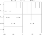
- FIG. 3 is a schematic diagram of frequency domain resource distribution of a 20 MHz bandwidth.
- FIG. 4 is a schematic diagram of a resource block division manner of a 20 MHz bandwidth.
- FIG. 5 is a schematic diagram of a resource block division manner of a 40 MHz bandwidth.
- FIG. 6 is a schematic diagram of a resource block division manner of an 80 MHz bandwidth.
- FIG. 7 is a schematic diagram showing an example of a bit sequence generation process.
- FIG. 8 is a schematic diagram of another example of a bit sequence generation process.
- Fig. 9 is a schematic diagram showing still another example of the bit sequence generation process.
- Fig. 10 is a schematic diagram showing still another example of the bit sequence generation process.
- Fig. 11 is a diagram showing still another example of the bit sequence generation process.
- Fig. 12 is a diagram showing still another example of the bit sequence generation process.
- Fig. 13 is a schematic diagram showing still another example of the bit sequence generation process.
- FIG. 14 is a schematic diagram of an example of a frequency domain resource to be allocated according to an embodiment of the present invention.
- 15 is a schematic diagram of a packet structure of 802.11ax.
- FIG. 16 is a schematic diagram showing an example of resource scheduling information according to an embodiment of the present invention.
- FIG. 17 is a schematic diagram of another example of resource scheduling information according to an embodiment of the present invention.
- FIG. 18 is a schematic flowchart of a method for resource scheduling according to an embodiment of the present invention.
- FIG. 19 is a schematic block diagram of an apparatus for resource scheduling according to an embodiment of the present invention.
- FIG. 20 is a schematic block diagram of an apparatus for resource scheduling according to another embodiment of the present invention.
- FIG. 21 is a schematic structural diagram of an apparatus for resource scheduling according to an embodiment of the present invention.
- FIG. 22 is a schematic structural diagram of an apparatus for resource scheduling according to another embodiment of the present invention.
- FIG. 1 is a schematic flowchart of a method 100 for resource scheduling according to an embodiment of the present invention, which is applied from a perspective of a transmitting end.
- the method 100 is applied to a wireless local area network, and the next-generation protocol followed by the wireless local area network agrees on a frequency to be allocated.
- the location of the resource block to which the domain resource may be divided, as shown in FIG. 1, the method 100 includes:
- the sending end generates resource scheduling information, where the resource scheduling information includes a bit sequence to be allocated to indicate that the to-be-assigned frequency domain resource is actually divided, and at least part of the bit sequence is used to indicate the to-be-allocated frequency. Whether one or more resource block positions in the resource block location that the domain resource may be divided into are to be allocated resource blocks to which the to-be-assigned frequency domain resource is actually divided;
- the method 100 can be applied to various communication for realizing multi-user transmission by means of resource scheduling.
- a system for example, a system that communicates by means of OFDMA or MU-MIMO.
- the method 100 can be applied to a Wireless Local Area Network (WLAN), for example, Wireless Fidelity (Wi-Fi).
- WLAN Wireless Local Area Network
- Wi-Fi Wireless Fidelity
- the WLAN system includes one or more access points AP21, and also includes one or more stations STA22. Data transmission is performed between the access point and the station, wherein the station determines the resource scheduled to be based on the preamble sent by the access point, and performs data transmission between the resource and the access point.
- the sending end is a network device
- the receiving end is a terminal device.
- a network side device in the communication system may be mentioned.
- it may be an access point (AP) in the WLAN, and the AP may also be called a wireless access point or bridge. Or a hotspot, etc., which can access a server or a communication network.
- AP access point
- the AP may also be called a wireless access point or bridge.
- a hotspot, etc. which can access a server or a communication network.
- a terminal device in a communication system may be cited.
- it may be a user station (STA, Station) in a WLAN.
- STA may also be referred to as a user, and may be a wireless sensor, a wireless communication terminal, or a mobile terminal, such as a mobile device.
- a telephone or "cellular" telephone
- a computer with wireless communication capabilities For example, it may be a portable, pocket-sized, hand-held, computer-integrated, wearable, or in-vehicle wireless communication device that exchanges voice, data, and the like communication data with a wireless access network.
- GSM global mobile communication system
- CDMA Code Division Multiple Access
- WCDMA Wideband Code Division Multiple Access
- GPRS General Packet Radio Service
- LTE Long Term Evolution
- LTE Long Term Evolution
- the network device may be a base station (BTS, Base Transceiver Station) in GSM or CDMA, may be a base station (NodeB) in WCDMA, or may be an evolved base station in LTE (eNB or e-NodeB, evolutional Node B) It may be a micro cell base station, which may be a micro base station (Micro), may be a pico base station (Pico), may be a home base station, or may be referred to as a femto cell base station (femto), which is not limited in the present invention.
- the terminal device may be a mobile terminal, a mobile user device, or the like, such as a mobile phone (or "cellular" phone).
- the rule for resource block size division in a WLAN system is: 26 subcarriers are used as one resource unit.
- the number of discrete Fourier transform/discrete Fourier transform (DFT/IDFT) points in the data symbol portion of the WLAN system is 256, that is, there are 256.
- left subcarriers -122 to subcarrier-2, and right subcarrier 2 to subcarrier 122 are used to carry data information, that is, 242 subcarriers are used to carry data information.
- Subcarrier-128 to subcarrier-123 and subcarrier 123 to subcarrier 128 are guard bands.
- the 242 subcarriers that are usually used to carry data information are divided into 9 sub-resource blocks, each sub-resource block includes 26 sub-carriers, and the remaining 8 unused sub-carriers, and the sub-resource blocks located at the center of the bandwidth cross the DC (ie,
- the method 100 of the embodiment of the present invention mainly relates to the allocation of 242 subcarriers for carrying data information.
- resource blocks For frequency domain resources of different bandwidths, the types of resource blocks (which may also be referred to as resource blocks) that can be included are different.
- the next-generation protocol followed by the WLAN stipulates a resource block location (resource profile) that may be allocated for various frequency domain resources to be allocated (20 MHz, 40 MHz, 80 MHz, or 160 MHz), and the sender generates and transmits the resource block.
- the resource scheduling information includes a bit sequence for indicating the allocated resource block to be allocated, and the receiving end can read the bit sequence to know which resource blocks the frequency domain resource to be allocated is divided into.
- the resource scheduling information may further include information about the scheduled receiving end corresponding to the foregoing divided resource blocks, so that the receiving end implements the uplink and downlink in the resource block allocated to itself by reading the foregoing resource scheduling information. Information transfer.
- the resource block positions that are likely to be allocated for various frequency domain resources to be allocated are stipulated in the next generation protocol (refer to the resource distribution map shown in FIG. 4, FIG. 5 or FIG. 6).
- the resource block location that the to-be-assigned frequency domain resource may be divided includes a default location, where the resource block corresponding to the default location is a resource block that is not specified by the bit sequence and is specified in the next-generation protocol.
- 1 bit may be used to indicate whether the resource block of the default location is allocated for use by the user.
- the frequency domain resource of 20 MHz bandwidth may include a central resource block (ie, a resource block located at a default location), and the default resource block may be a 1 ⁇ 26 type resource block. That is, a resource block that spans DC (ie, subcarrier-1, 0, 1) and includes 26 subcarriers.
- the default resource block exists by default in the communication system, and is independently allocated, that is, each resource of the 20 MHz bandwidth to be allocated is divided into a default resource block of type 1 ⁇ 26 at its central location.
- the default resource block is independently allocated to a receiving end, and the receiving end to which the default resource block is allocated may be the same as or different from the receiving end allocated to the left or right side of the default resource block.
- the present invention is not particularly limited.
- the receiving end to which the default resource block is allocated when the receiving end to which the default resource block is allocated is the same as the receiving end to which the resource block adjacent to the left or right side of the default resource block is allocated, it indicates that the 20 MHz bandwidth is allocated to only one user. Otherwise, the receiving end to which the default resource block is assigned is different from the receiving end to which the resource block adjacent to the left or right side of the default resource block is allocated.
- the frequency domain resources of the 20 MHz bandwidth also include the following four types of resource blocks located on the left or right side of the default resource block of the 20 MHz bandwidth frequency domain resource center, namely:
- a 1 ⁇ 26 type resource block the smallest resource block that may be divided in a 20 MHz bandwidth, indicates that one resource block is composed of one sub resource block (ie, 26 subcarriers).
- a 2 ⁇ 26 type resource block indicates that one resource block is composed of two sub resource blocks (ie, 2 ⁇ 26 subcarriers).
- a 4 ⁇ 26 type resource block indicates that one resource block is composed of four sub resource blocks (ie, 4 ⁇ 26 subcarriers).
- a resource block of type 242 the largest resource block that may be divided in a 20 MHz bandwidth, indicates that one resource block is composed of 242 subcarriers.
- the resource block of the 4 ⁇ 26 type includes 106 subcarriers, that is, includes 102 data subcarriers and 4 pilot subcarriers.
- 106 subcarriers that is, includes 102 data subcarriers and 4 pilot subcarriers.
- the resource block distribution picture of the 20 MHz bandwidth is or described as four layers:
- the first layer is a distribution map of a 1 ⁇ 26 type resource block and a default resource block (ie, a 1 ⁇ 26 type resource block located at a central position of the 20 MHz bandwidth), on the left and right sides of the default resource block located at the center, respectively
- the second layer is a distribution map of a 2 ⁇ 26 type resource block and a default resource block (ie, a 1 ⁇ 26 type resource block located at a central position of the 20 MHz bandwidth), on the left and right sides of the default resource block located at the center, respectively
- the third layer is a distribution map of a 4 ⁇ 26 type resource block and a default resource block (ie, a 1 ⁇ 26 type resource block located at a central position of the 20 MHz bandwidth), on the left and right sides of the default resource block located at the center, respectively
- the fourth layer is a resource block distribution map of type 242.
- the 242 type resource block includes the subcarrier in which the aforementioned symmetric center is located.
- the frequency domain resource of the 20 MHz bandwidth (that is, an example of the frequency domain resource to be allocated) includes 242 subcarriers, and can be divided into any resource blocks from the first layer to the third layer in FIG. 4, The divided resource blocks are allocated to multiple users, and each user can only allocate one of the divided resource blocks.
- the frequency domain resource spectrum of the 20 MHz bandwidth may be divided into resource blocks in the fourth layer.
- the frequency domain resource of the 20 MHz bandwidth is allocated to one user, and the bandwidth indication information may be described later.
- the single user transmission indication bit indicates resource allocation.
- the frequency domain resource spectrum of the 20 MHz bandwidth may be divided into resource blocks in the fourth layer.
- the frequency domain resource of the 20 MHz bandwidth is allocated to multiple users MU-MIMO, and the bandwidth may be described later.
- the indication information and the multi-user transmission indication bit indicate the case of resource allocation.
- the resource scheduling method of the present invention mainly relates to a case where a frequency domain resource of a 20 MHz bandwidth is composed of any one of the first to third layers and is allocated to a plurality of users.
- FIG. 7 shows an example of a frequency domain resource of a 20 MHz bandwidth.
- the frequency domain resources (in order from left to right in FIG. 7) are divided into two 2 ⁇ 26 type resources.
- Blocks ie, resource block #1 and resource block #2
- a 1 ⁇ 26 type resource block ie, resource block #0, which is a default resource block
- a 4 ⁇ 26 type resource block ie, a resource block #3.
- FIG. 8 shows another example of a frequency domain resource of a 20 MHz bandwidth.
- the frequency domain resources (in order from left to right in FIG. 8) are divided into a 2 ⁇ 26 type.
- a resource block ie, resource block #1'
- three resource blocks of type 1 ⁇ 26 ie, resource block #2', resource block #3', and resource block #0', where resource block #0' is
- the default resource block is composed of one 4 ⁇ 26 type resource block (ie, resource block #4').
- the frequency domain resource to be allocated includes a symmetric center.
- the frequency domain resource of the 20 MHz bandwidth includes a resource block located at the center (ie, a resource block of the above default location), and the resources on both sides of the resource block located at the center
- the source block positions are symmetrically distributed, that is, the centrally located resource block can serve as a symmetric center of the frequency domain resource of 20 MHz bandwidth.
- a frequency domain resource of 40 MHz bandwidth may be considered to be composed of two 20 MHz frequency domain resources.
- each frequency domain resource of 20 MHz bandwidth may include a default resource block located at the center of the 20 MHz bandwidth (ie, a resource block located at a default location).
- the configuration and allocation method of the default resource blocks (two in total) in the 40 MHz bandwidth are similar to the configuration and allocation method of the default resource blocks in the above-described 20 MHz bandwidth.
- detailed description thereof will be omitted.
- the frequency domain resources of the 40 MHz bandwidth include the following five types of resource blocks located to the left or right of the frequency center of the 40 MHz bandwidth frequency domain, namely:
- a 1 ⁇ 26 type resource block the smallest resource block that may be divided in a 40 MHz bandwidth, indicates that one resource block is composed of one sub resource block (ie, 26 subcarriers).
- a 2 ⁇ 26 type resource block indicates that one resource block is composed of two sub resource blocks (ie, 2 ⁇ 26 subcarriers).
- a 4 ⁇ 26 type resource block indicates that one resource block is composed of four sub resource blocks (ie, 4 ⁇ 26 subcarriers).
- the resource block distribution picture of the 40 MHz bandwidth is or described as five layers:
- the first layer is a distribution map of a 1 ⁇ 26 type resource block and a default resource block (ie, a 1 ⁇ 26 type resource block located at a center position of each 20 MHz bandwidth), respectively on the left and right sides of each default resource block.
- a detailed description thereof will be omitted.
- the second layer is a distribution map of a 2 ⁇ 26 type resource block and a default resource block (ie, a 1 ⁇ 26 type resource block located at a center position of each 20 MHz bandwidth), respectively on the left and right sides of each default resource block.
- There are 2 2 ⁇ 26 type resource blocks for example, position #E and position #F in Figure 5
- the distribution of four 2 ⁇ 26 type resource blocks in the 20 MHz bandwidth is similar to the distribution of the 2 ⁇ 26 type resource blocks shown in the second layer in FIG. 4 .
- a detailed description thereof will be omitted.
- the third layer is a distribution map of a 4 ⁇ 26 type resource block and a default resource block (ie, a 1 ⁇ 26 type resource block located at a center position of each 20 MHz bandwidth), respectively on the left and right sides of each default resource block.
- a 4 ⁇ 26 type resource block for example, position #C and position #D in FIG. 5
- the distribution of the resource blocks of the 4 ⁇ 26 type shown is similar, and a detailed description thereof will be omitted herein to avoid redundancy.
- the fourth layer is a resource block distribution map of type 242.
- the fifth layer is a resource block distribution map of type 4 ⁇ 242.
- the frequency domain resource of the 40 MHz bandwidth (that is, an example of the frequency domain resource to be allocated) includes 484 subcarriers, and can be divided into any resource blocks from the first layer to the fourth layer in FIG. 5, The divided resource blocks are allocated to multiple users, and each user can only allocate one of the divided resource blocks.
- the frequency domain resource spectrum of the 40 MHz bandwidth may be divided into resource blocks in the fifth layer.
- the frequency domain resource of the 40 MHz bandwidth is allocated to one user, and the bandwidth indication information described later may be adopted.
- the single user transmission indication bit indicates resource allocation.
- the frequency domain resource spectrum of the 40 MHz bandwidth may be divided into resource blocks in the fifth layer.
- the frequency domain resource of the 40 MHz bandwidth is allocated to multiple users MU-MIMO, and the bandwidth may be described later.
- the indication information and the multi-user transmission indication bit indicate the case of resource allocation.
- the resource scheduling method of the present invention mainly relates to a case where a frequency domain resource of a 40 MHz bandwidth is composed of any one of the first to fourth layers and is allocated to a plurality of users.
- FIG. 10 shows an example of a frequency domain resource of a 40 MHz bandwidth.
- the frequency domain resources (in order from left to right in FIG. 10) are divided into two 2 ⁇ 26 type resources.
- Block ie, resource block #1" and resource block #2"
- a 1 ⁇ 26 type resource block ie, resource block #0
- a 4 ⁇ 26 type resource block ie, , resource block #3
- a 242 type resource block ie, resource block #4"
- the frequency domain resource to be allocated includes a symmetric center.
- the resource blocks on both sides of the frequency domain resource center frequency of the 40 MHz bandwidth are symmetrically distributed, that is, the center frequency point can serve as a symmetric center of the frequency domain resource of 40 MHz bandwidth.
- the resource block location that the to-be-assigned frequency domain resource may be divided includes a default location, where the resource block corresponding to the default location is a resource block that is not specified by the bit sequence and is specified in the next-generation protocol.
- 5 bits are respectively used to indicate whether resource blocks of the five default locations under the bandwidth are allocated for use by the user.
- the 80 MHz bandwidth frequency domain resource may include a centrally located default resource block (ie, a resource block located at a default location), and the default resource block may be a 1 ⁇ 26 type resource block. That is, a resource block that spans DC (ie, subcarrier-1, 0, 1) and includes 26 subcarriers.
- the default resource block exists by default in the communication system, and is allocated independently.
- each of the 80 MHz bandwidth resources to be allocated is divided into a 1 ⁇ 26 type default resource block at its central location, and the default resource block is independently allocated to a receiving end, and the receiving end to which the default resource block is allocated and the receiving end to which the resource block adjacent to the left or right side of the default resource block is allocated may be the same or different, and the present invention is not particularly limited. .
- the 80 MHz bandwidth when the receiving end to which the default resource block is allocated is the same as the receiving end to which the resource block adjacent to the left or right side of the default resource block is allocated, it indicates that the 80 MHz bandwidth is allocated to only one user. Otherwise, the receiving end to which the default resource block is assigned is different from the receiving end to which the resource block adjacent to the left or right side of the default resource block is allocated.
- each frequency domain resource of the 80 MHz bandwidth can be regarded as composed of two 40 MHz frequency domain resources and one default resource block located at the symmetric center
- each frequency domain resource of 40 MHz bandwidth can be regarded as composed of two 20 MHz frequency domain resources.
- each 20 MHz bandwidth frequency domain resource may include a default resource block located at the 20 MHz bandwidth center (ie, a resource block located at a default location).
- the frequency domain resources of the 80 MHz bandwidth include the following six types of resource blocks located on the left or right side of the default resource block of the 80 MHz bandwidth frequency domain resource center, namely:
- a 1 ⁇ 26 type resource block the smallest resource block that may be divided in an 80 MHz bandwidth, indicates that one resource block is composed of one sub resource block (ie, 26 subcarriers).
- a 2 ⁇ 26 type resource block indicating that one resource block consists of two sub-resource blocks (ie, 2 ⁇ 26 Subcarrier).
- a 4 ⁇ 26 type resource block indicates that one resource block is composed of four sub resource blocks (ie, 4 ⁇ 26 subcarriers).
- a 2 ⁇ 242 type resource block indicates that one resource block is composed of 2 ⁇ 242 subcarriers.
- a resource block of type 996 the largest resource block that may be divided in the 80 MHz bandwidth, indicates that one resource block is composed of 996 subcarriers.
- the resource block distribution picture of the 40 MHz bandwidth is or described as six layers:
- the first layer is a 1 ⁇ 26 type resource block and a default resource block (ie, a 1 ⁇ 26 type resource block located at a center position of every 20 MHz bandwidth and a 1 ⁇ 26 type resource block located at a center position of an 80 MHz bandwidth).
- the distribution map has four 1 ⁇ 26 type resource blocks on the left and right sides of the default resource block at the center of each 20 MHz bandwidth, wherein the distribution of the 1 ⁇ 26 type resource blocks in each 20 MHz bandwidth is shown in FIG.
- the distribution of the 1 ⁇ 26 type resource blocks shown in the first layer is similar, and a detailed description thereof will be omitted herein to avoid redundancy.
- the second layer is a 2 ⁇ 26 type resource block and a default resource block (ie, a 1 ⁇ 26 type resource block located at a center position of every 20 MHz bandwidth and a 1 ⁇ 26 type resource block located at a center position of an 80 MHz bandwidth).
- the distribution map has two 2 ⁇ 26 type resource blocks on the left and right sides of the default resource block at the center of each 20 MHz bandwidth, wherein the distribution of the 2 ⁇ 26 type resource blocks in each 20 MHz bandwidth is the same as that in FIG.
- the distribution of the 2 ⁇ 26 type resource blocks shown in the second layer is similar, and a detailed description thereof will be omitted herein to avoid redundancy.
- the third layer is a 4 ⁇ 26 type resource block and a default resource block (ie, a 1 ⁇ 26 type resource block located at a center position of every 20 MHz bandwidth and a 1 ⁇ 26 type resource block located at a center position of an 80 MHz bandwidth).
- the distribution map has a 4 ⁇ 26 type resource block (for example, position #e and position #f in FIG. 6) on the left and right sides of the default resource block at the center position of each 20 MHz bandwidth, wherein each 20 MHz bandwidth
- the distribution of the 4 ⁇ 26 type resource blocks in the middle is similar to the distribution of the 4 ⁇ 26 type resource blocks shown in the third layer in FIG. 4, and a detailed description thereof will be omitted herein for avoiding redundancy.
- the fourth layer is a distribution map of the resource block profile of the 242 type and the default resource block (ie, the 1 ⁇ 26 type resource block located at the center of the 80 MHz bandwidth) at the left and right sides of the center frequency point of each 40 MHz.
- the distribution of resource blocks of the 242 type shown in the fourth layer in FIG. 5 is similar, and a detailed description thereof will be omitted herein to avoid redundancy.
- the fifth layer is a distribution map of a 2 ⁇ 242 type resource block map and a default resource block (ie, a 1 ⁇ 26 type resource block located at a central position of the 80 MHz bandwidth), at a default resource block located at a central location of 80 MHz.
- the distribution of the resource blocks of the 242 type shown in the fifth layer is similar, and a detailed description thereof will be omitted herein to avoid redundancy.
- the sixth layer is a resource block distribution map of type 996.
- the frequency domain resource of the 80 MHz bandwidth (that is, an example of the frequency domain resource to be allocated) includes 996 subcarriers, and can be divided into any resource blocks in the first layer to the fifth layer in FIG.
- the divided resource blocks are allocated to multiple users, and each user can only allocate one of the divided resource blocks.
- the frequency domain resource spectrum of the 80 MHz bandwidth may be divided into resource blocks in the sixth layer.
- the frequency domain resource of the 80 MHz bandwidth is allocated to one user, and the bandwidth indication information described later may be adopted.
- the single user transmission indication bit indicates resource allocation.
- the frequency domain resource spectrum of the 80 MHz bandwidth may be divided into resource blocks in the sixth layer.
- the frequency domain resource of the 80 MHz bandwidth is allocated to multiple users MU-MIMO, and the bandwidth may be described later.
- the indication information and the multi-user transmission indication bit indicate the case of resource allocation.
- the resource scheduling method of the present invention mainly relates to a case where a frequency domain resource of an 80 MHz bandwidth is composed of any one of the first to fifth layers and is allocated to a plurality of users.
- FIG. 11 shows an example of a frequency domain resource of an 80 MHz bandwidth.
- the frequency domain resources (in order from left to right in FIG. 11) are divided into a resource block of 4 ⁇ 26 type.
- resource block #1"' a 1 ⁇ 26 type resource block (ie, resource block #0”', which is a default resource block), a 4 ⁇ 26 type resource block (ie, resource block #2) "'), a 242 type resource block (ie, resource block #3"'), a 1x26 type resource block (ie, resource block #00"', which is the default resource block) and a 2x242 type Resource block (ie, resource block #4"').
- the frequency domain resource to be allocated includes a symmetric center.
- the frequency domain resource of the 80 MHz bandwidth includes a resource block located at the center (ie, a resource block of the above default location), and each resource on both sides of the resource block located at the center
- the source block positions are symmetrically distributed, that is, the centrally located resource block can serve as a symmetric center of the frequency domain resource of the 80 MHz bandwidth.
- the 160MHz bandwidth frequency domain resource can be regarded as composed of two 80MHz frequency domain resources. Accordingly, each 80MHz bandwidth frequency domain resource may include a default resource block located at the 80MHz bandwidth center (ie, a resource block located at a default location). And, the frequency domain resource of each 20 MHz bandwidth in the 160 MHz frequency domain resource may include a default resource block located at the center of the 20 MHz bandwidth (ie, a resource block located at a default location).
- 10 bits are respectively used to indicate whether resource blocks of the 10 default locations in the bandwidth are respectively allocated to the user.
- the 160MHz bandwidth frequency domain resources also include the following seven types of resource blocks located to the left or right of the 160MHz bandwidth frequency domain resource center frequency point, namely:
- a 1 ⁇ 26 type resource block the smallest resource block that may be divided in an 80 MHz bandwidth, indicates that one resource block is composed of one sub resource block (ie, 26 subcarriers).
- a 2 ⁇ 26 type resource block indicates that one resource block is composed of two sub resource blocks (ie, 2 ⁇ 26 subcarriers).
- a 4 ⁇ 26 type resource block indicates that one resource block is composed of four sub resource blocks (ie, 4 ⁇ 26 subcarriers).
- a 2 ⁇ 242 type resource block indicates that one resource block is composed of 2 ⁇ 242 subcarriers.
- a resource block of type 996 indicating that one resource block is composed of 996 subcarriers.
- a 2 ⁇ 996 type resource block the largest resource block that may be divided in a 160 MHz bandwidth, indicating that one resource block is composed of 2 ⁇ 996 subcarriers.
- the resource block distribution picture of the 160 MHz bandwidth is or described as seven layers:
- the first layer is a 1 ⁇ 26 type resource block and a default resource block (ie, a 1 ⁇ 26 type resource block located at a center position per 20 MHz bandwidth and a 1 ⁇ 26 type resource block located at a center position per 80 MHz bandwidth)
- the distribution map has four 1 ⁇ 26 type resource blocks on the left and right sides of the default resource block at the center of each 20 MHz bandwidth, wherein the distribution of 1 ⁇ 26 type resource blocks in each 20 MHz bandwidth is shown in FIG. 4 .
- the distribution phase of the 1 ⁇ 26 type resource block shown in the first layer Here, in order to avoid redundancy, a detailed description thereof will be omitted.
- the second layer is a 2 ⁇ 26 type resource block and a default resource block (ie, a 1 ⁇ 26 type resource block located at a center position per 20 MHz bandwidth and a 1 ⁇ 26 type resource block located at a center position per 80 MHz bandwidth)
- the distribution map has two 2 ⁇ 26 type resource blocks on the left and right sides of the default resource block at the center position of each 20 MHz bandwidth, wherein the distribution of 2 ⁇ 26 type resource blocks in each 20 MHz bandwidth is shown in FIG.
- the distribution of the 2 ⁇ 26 type resource blocks shown in the second layer is similar, and a detailed description thereof will be omitted herein to avoid redundancy.
- the third layer is a 4 ⁇ 26 type resource block and a default resource block (ie, a 1 ⁇ 26 type resource block located at a center position per 20 MHz bandwidth and a 1 ⁇ 26 type resource block located at a center position per 80 MHz bandwidth)
- the distribution map has a 4 ⁇ 26 type resource block on the left and right sides of the default resource block at the center position of each 20 MHz bandwidth, wherein the distribution of 4 ⁇ 26 type resource blocks in each 20 MHz bandwidth is shown in FIG. 4 .
- the distribution of the 4 ⁇ 26 type resource blocks shown in the third layer is similar, and a detailed description thereof will be omitted herein to avoid redundancy.
- the fourth layer is a distribution map of a resource block profile of 242 types and a default resource block (ie, a 1 ⁇ 26 type resource block located at a center position of each 80 MHz bandwidth), at the left and right of each center frequency point of each 40 MHz.
- a default resource block ie, a 1 ⁇ 26 type resource block located at a center position of each 80 MHz bandwidth
- the fifth layer is a distribution map of a 2 ⁇ 242 type resource block map and a default resource block (ie, a 1 ⁇ 26 type resource block located at a center position of every 80 MHz bandwidth), and a default resource block at a central location of 80 MHz.
- a 2 ⁇ 242 type resource block map and a default resource block ie, a 1 ⁇ 26 type resource block located at a center position of every 80 MHz bandwidth
- a default resource block at a central location of 80 MHz.
- the sixth layer is a distribution map of the resource block profile of the 996 type and the default resource block (ie, a 1 ⁇ 26 type resource block located at the center of each 80 MHz bandwidth), respectively on the left and right sides of the center frequency point of 160 MHz.
- the distribution of the 242 type resource blocks in the 80 MHz bandwidth is similar to the distribution of the 996 type resource blocks shown in the sixth layer in FIG. 6.
- detailed description thereof is omitted. .
- the seventh layer is a resource block distribution map of type 2 ⁇ 996.
- a frequency domain resource of 160 MHz bandwidth (ie, an example of a frequency domain resource to be allocated) includes 2 ⁇ 996 subcarriers, and may be divided into any one of the first layer to the sixth layer.
- a resource block, the divided resource blocks are allocated to multiple users, and each user can only allocate one of the divided resource blocks.
- the frequency domain resource spectrum of the 160 MHz bandwidth may be divided into resource blocks in the seventh layer.
- the 160 MHz bandwidth frequency domain resource is allocated to one user, and the bandwidth indication information may be adopted later.
- the single user transmission indication bit indicates resource allocation.
- the frequency domain resource spectrum of the 160 MHz bandwidth may be divided into resource blocks in the seventh layer.
- the 160 MHz bandwidth frequency domain resource is allocated to multiple users MU-MIMO, and the bandwidth may be described later.
- the indication information and the multi-user transmission indication bit indicate the case of resource allocation.
- the resource scheduling method of the present invention mainly relates to a case where a frequency domain resource of a 160 MHz bandwidth is composed of any one of the first to sixth layers and is allocated to a plurality of users.
- the frequency domain resource to be allocated includes a symmetric center.
- the resource blocks on the left and right sides of the center frequency point of the 160 MHz bandwidth frequency domain resource are symmetrically distributed, that is, the center frequency point can serve as a symmetric center of the frequency domain resource of 160 MHz bandwidth.
- the above describes the resource block positions in which various frequency domain resources to be allocated may be divided.
- the following describes the process of generating resource scheduling information based on the resource block positions that may be divided.
- the sending end needs to perform resource scheduling, for example, the resource scheduling information is used to notify the receiving end (the number of the receiving end may be one or more) corresponding to the resource block, so that the receiving end passes the resource block. Transfer.
- the sender can notify the following information in the system through the bit sequence, or bit map, to:
- the current resource block partitioning of the frequency domain resource to be allocated that is, the number of subcarriers included in each divided resource block, or the type of each resource block that is divided.
- the resource block partitioning situation also includes the location of each resource block in the frequency domain resource to be allocated.
- a simplified resource block partitioning instruction is performed by using resource blocks that may be divided under each bandwidth of the protocol, for example, the number of pieces and location information of each type of frequency domain resource block under each bandwidth. Therefore, the receiving end may determine each resource block allocated by the transmitting end based on the foregoing information, and in combination with the information of the scheduled receiving end, the receiving end may perform subsequent information transmission on the scheduled corresponding resource block.
- the following various embodiments propose efficient indication of the above-mentioned frequency domain resources (bandwidth) to be allocated.
- the bit sequence includes a plurality of first type bits, the plurality of first type bits are in one-to-one correspondence with a plurality of resource block position pairs, and the first type of bits is used to indicate that the corresponding resource block position is aligned.
- one resource block location pair includes two consecutive minimum resource block locations on the same side of a default location.
- the bit sequence includes at least: a plurality (two or more) of the first type of bits, wherein The first type of bits is used to indicate 2 consecutive possible partitioned minimum resource block positions (1 ⁇ 26) on the same side of the default location (ie, the location where the default resource block is located) in the frequency domain resource to be allocated. Whether it is divided into the same resource block to be allocated.
- the same side of the default position in every 20 MHz bandwidth has four 1 ⁇ 26 resource block positions, and one side of one default position may include two.
- a resource block position pair, wherein each resource block position pair may include two consecutive 1 ⁇ 26 resource block positions, wherein each 1 ⁇ 26 resource block position belongs to and belongs to only one resource block position pair.
- the default location may be multiple. If there are multiple default locations, one side of the foregoing default location refers to the bandwidth resource between the two default locations.
- the method further includes: when the two consecutive first type of bits indicate that the same resource block to be allocated is divided, the bit sequence further includes multiple (two or more) fourth type bits The fourth type of bits is used to indicate whether two consecutive second small resource block positions (positions of 2 ⁇ 26 type resource blocks) are divided into the same resource block.
- the first type of bits may be included.
- the manner of indicating the partitioning of the resource blocks may be performed in other manners, or may be performed according to the above indication principle until the indication is complete. Resource block division. It can be seen that for larger bandwidths, more bits are needed to indicate the partitioning of all resource blocks.
- the resource scheduling information further includes first indication information used to indicate the frequency domain resource to be allocated.
- the method shown in FIG. 7 or FIG. 8 is used to indicate the first indication of the frequency domain resource to be allocated.
- the information is 20 MHz
- the bit sequence includes at least four first type bits, wherein each bit corresponds to two 1 ⁇ 26 resource block positions arranged in order from left to right, for indicating whether the two 1 ⁇ 26 The resource block locations are divided into the same resource blocks to be allocated;
- the scheme also includes a fourth type of bit:
- the bit sequence further includes a bit #5 for indicating the bit. Whether the location of the 2 ⁇ 26 resource block corresponding to #1 and bit #2 is divided into the same resource block to be allocated; or
- the bit sequence further includes a bit #6 for indicating the bit. Whether the 2 ⁇ 26 resource block position corresponding to #3 and bit #4 is divided into the same resource block to be allocated.
- bit #1 and bit #2, or bit #3 and bit #4 indicate that the two 1 ⁇ 26 resource blocks are not divided into the same waiting
- the resource block is allocated without the fourth bit.
- the first type of bits may be included.
- other manners are used to indicate the division of other resource blocks, and other indications may be used according to the above indication principles.
- the bit indicates whether two consecutive second small resource block positions that may be divided are the allocated resource blocks to be allocated until the resource block partitioning condition of the full portion is indicated. In a preferred manner, for a bandwidth of 40 MHz, 80 MHz, and 160 MHz, only two consecutive partitions that are located on the same side of the default location in the frequency domain resource to be allocated (ie, the location where the default resource block is located) may be divided.
- the minimum resource block position (1 ⁇ 26) is divided into the same resource block to be allocated, or only 2 consecutive possible minimum resource block positions and 2 consecutive second small resource blocks that may be divided are indicated. Whether the location is the allocated resource block to be allocated, and for a larger resource block location, other possible implementation manners are used for indication.
- the bit sequence includes a plurality of second type bits, where the second type of bits is used to indicate whether a maximum resource block location located on one side of the symmetric center is the resource block to be allocated.
- FIG. 9 , FIG. 10 and FIG. 11 are schematic diagrams showing a result of resource block partitioning and a corresponding schematic diagram of a bit sequence for indicating a partitioned resource block to be allocated.
- the bit sequence includes at least: a plurality of (two or more) second type bits, wherein the second type of bits is used to indicate that when the frequency domain resource to be allocated is allocated to When a plurality of users are located, the maximum resource block position that may be divided on one side of the symmetric center in the to-be-assigned frequency domain resource is the divided resource block to be allocated.
- the maximum resource block location on the symmetric center side is different under each bandwidth. For example, if the frequency domain resource to be allocated is 20 MHz, the maximum resource block position that may be divided is a 4 ⁇ 26 type resource block.
- the maximum resource block position that may be divided is the location of the resource block of type 242; for example, if the frequency domain resource to be allocated is 80 MHz, the maximum may be divided.
- the resource block location is the location of the resource block of type 2 ⁇ 242; for example, if the frequency domain resource to be allocated is 160 MHz, the maximum resource block location that may be divided is the location of the resource block of type 996.
- the method further includes: when a certain second type of bit indicates that the maximum resource block position that may be divided is not the allocated resource block to be allocated, and further includes a fifth type of bit, which is indicated for the second type of bit Within the scope of the resource block location, the fifth class of bits is used to indicate whether the second largest resource block location that may be partitioned is the allocated resource block to be allocated.
- the second type of bits may be included.
- other manners may be used to indicate the division of other resource blocks, and other bits may be used according to the above indication principle. Indicates whether the third largest resource block location is the allocated resource block to be allocated until the resource block partitioning condition of the full portion is indicated.
- 40 MHz, 80 MHz, and 160 MHz only indicate whether the maximum resource block position that may be divided is the allocated resource block to be allocated, or only indicates the maximum resource block position and whether the second largest resource block position is divided.
- the resource blocks to be allocated are indicated, and for other resource block locations, other possible implementation manners are used for indication.
- the resource scheduling information further includes first indication information used to indicate the frequency domain resource to be allocated.
- the first indication information of the frequency domain resource to be allocated is 20 MHz
- the bit sequence includes at least 2 bits (that is, an example of the second type of bits)
- the at least two Bits #A and #B in the bits are respectively used to indicate whether the 4x26 type resource block position to the left or right of the symmetric center of the 20 MHz bandwidth (ie, the default position in the 20 MHz bandwidth) is the divided waiting Allocate resource blocks.
- the bit #A indicates the right side
- the bit #B indicates the left side, and the principle is not described here.
- the example of FIG. 9 may further include:
- the bit sequence further includes the bit #C and the bit #D, and the bit #C is used to indicate Whether the 2 ⁇ 26 type resource block position of the front end corresponding to the bit #A is divided into the same resource block to be allocated, and the bit #D is used to indicate whether the 2 ⁇ 26 type resource block position of the back end corresponding to the bit #A is Is the resource block to be allocated divided; or,
- bit sequence further includes bit #E and bit #F, and bit #E is used for Indicates whether the 2 ⁇ 26 type resource block position of the front end corresponding to the bit #B is divided into the same resource block to be allocated, and the bit #F is used to indicate the 2 ⁇ 26 type resource of the back end corresponding to the bit #B.
- the block position is the resource block to be allocated that is divided.
- the first indication information for indicating the frequency domain resource to be allocated is 40 MHz
- the bit sequence includes at least 2 bits (ie, another example of the second type of bits), where the at least Bits #A' and #B' in 2 bits are respectively used to indicate whether the 242-type resource block position on the left or right side of the symmetric center of the 40 MHz bandwidth (ie, the center frequency of the 40 MHz bandwidth) is divided.
- the resource block to be allocated may be that the bit #A' indicates the right side and the bit #B' indicates the left side, and the principle is not described again.
- the indication of the continuation may be adopted in other manners, and is not limited to the present embodiment.
- the first indication information indicating the frequency domain resource to be allocated is 80 MHz
- the bit sequence includes at least 2 bits (that is, another example of the second type of bits), the bit sequence.
- the method includes at least two bits, and the bits #A" and the bits #B" of the at least two bits are respectively used to indicate the left or right side of the symmetric center of the 80 MHz bandwidth (ie, the default position at the center of the 80 MHz bandwidth). Whether the resource block position of the 2 ⁇ 242 type is the allocated resource block to be allocated.
- the bit #A" indicates the right side
- the bit #B" indicates the left side, and the principle is not described again. .
- the manner of the present embodiment may be continued to indicate whether the location of the 242 resource block in the location range of the 2 ⁇ 242 resource block is the allocated to be allocated. Resource block. For subsequent resource blocks, other manners may be used to continue the indication, and are not limited to the present embodiment.
- the bit sequence includes two third-type bits, and the two third-type bits are in one-to-one correspondence with two resource block position groups located at two sides of the symmetric center, and the third type of bits is used to indicate Whether the resource block positions in the corresponding resource block location group are all the resource blocks to be allocated, wherein one resource block location group includes the plurality of minimum resource block locations on the same side of the center of the frequency domain resource to be allocated.
- FIG. 13 is a simplified diagram of a resource block partitioning result and a corresponding schematic diagram of a bit sequence for indicating a partitioned resource block to be allocated.
- the bit sequence includes at least: a plurality of third type bits, some of which are used for the third type of bits.
- the symmetric center located in the frequency domain resource to be allocated eg, the default location of the 20 MHz bandwidth, the center frequency of the 40 MHz bandwidth, the centrally located default location of the 80 MHz bandwidth, and the center frequency of the 160 MHz bandwidth
- the plurality of divided minimum resource block positions are all the allocated resource blocks to be allocated, and the other third type of bits are respectively used to indicate that the other side of the default location in the to-be-assigned frequency domain resource may be divided.
- the plurality of minimum resource block positions are all the allocated resource blocks to be allocated.
- the minimum resource block size in each bandwidth is generally 1 ⁇ 26. For the location, refer to the previous detailed description, and details are not described here.
- the symmetric center side may include one resource block position group, or each resource block position group may include all 1 ⁇ 26 resource block positions except the default position on the symmetric center side, where each 1 ⁇ The resource block location of 26 belongs to and belongs to only one resource block location group.
- the method further includes: when a certain third type of bit indicates that the plurality of minimum resource block positions that may be divided are not all the allocated resource blocks to be allocated, and further includes a sixth type of bit, for the third Within the range of the location of the resource block indicated by the class bit, the sixth class of bits is used to indicate whether the plurality of second small resource block locations that may be divided are all the allocated resource blocks to be allocated.
- the third type of bits may be included.
- other manners may be used to indicate the division of other resource blocks, and other bits may be used according to the above indication principle. Indicates whether the third largest resource block location is the allocated resource block to be allocated until the resource block partitioning condition of the full portion is indicated. In a preferred mode, 40 MHz, 80 MHz, and 160 MHz only indicate whether the minimum resource block position that may be divided is the allocated resource block to be allocated, or only indicates the minimum resource block position and whether the second small resource block position is divided.
- the resource blocks to be allocated are indicated, and for other resource block locations, other possible implementation manners are used for indication.
- the foregoing mentioned bit sequence for indicating resource block partitioning includes a zeroth class bit, where the bit indicates that a maximum resource block position that may be divided corresponding to a certain bandwidth is a divided resource block to be allocated. That is, the bit indicates that the largest resource block is for MU-MIMO transmission.
- the allocated resource blocks to be allocated are allocated to the corresponding sites by other resource indication information.
- the maximum resource block position corresponding to a certain bandwidth may be divided, for example, the fourth layer of FIG. 4 for the 20 MHz bandwidth described above, the fifth layer of FIG. 5 for 40 MHz, and the sixth layer of FIG. 6 for 80 MHz, for The seventh layer of 160MHz bandwidth.
- the zeroth class bit indicates that the maximum resource block position that may be divided corresponding to the current bandwidth is not the allocated resource block to be allocated
- the subsequent need to include the foregoing first type bit, the second type bit or the first Three types of bits or other types of bits indicate the partitioning of resource blocks. If the zeroth class bit indicates that the maximum resource block location corresponding to the current bandwidth is the allocated resource block to be allocated, it is not necessary to include other bit sequences to indicate the partitioning of the resource block.
- each implementation adopts an indication of resource block division in a similar manner. That is to say, for the bandwidth of 40 MHz, 80 MHz, and 160 MHz, the foregoing indication method is used as a whole to indicate.
- the sending end acquires N mapping rules, where the mapping rules are used to indicate a mapping relationship between the determination result and the indication identifier, and the determination result is Obtaining N ⁇ 1 based on the relationship between the number of preset subcarriers corresponding to the mapping rule and the determination object;
- the number of subcarriers included in each of the frequency domain resource blocks is used as the determination object, and determined according to the N mapping rules.
- bit sequence is used to indicate the number of subcarriers included in each frequency domain resource block and the location of each frequency domain resource block in the to allocate frequency domain resource
- the preset number of subcarriers is determined according to a type of the resource block.
- the preset number of subcarriers may be determined according to the number of possible resource blocks in the WLAN system.
- the sending end acquires N mapping rules, including:
- the bandwidth of the frequency domain resource to be allocated (that is, the number of subcarriers included in the frequency domain resource to be allocated (hereinafter, the subcarrier included in the frequency domain resource to be allocated) may be used.
- the DC null subcarrier and the sideband protection null subcarrier are not included.
- the size of the sub resource block as described above ie, the minimum value of the preset subcarrier number
- the maximum value of the number of subcarriers included in the resource block in the bandwidth determines the preset rule.
- the frequency domain resource may include three types of resource blocks as shown in FIG. 4, and therefore, the preset number of subcarriers may be:
- the frequency domain resource may include four types of resource blocks as shown in FIG. 5, and therefore, the preset number of subcarriers may be:
- the frequency domain resource may include the five types of resource blocks shown in FIG. 6. Therefore, the preset number of subcarriers may be:
- the frequency domain resource may include six types of resource blocks, that is, the preset number of subcarriers may be:
- the receiving end may also adopt a similar method and process to determine the preset number of subcarriers, and in order to ensure the reliability of the method 100, it is necessary to ensure the predetermination determined by the transmitting end and the receiving end. Set the number of subcarriers to be the same.
- the method for determining the number of preset subcarriers enumerated above is only an exemplary description, and the present invention is not limited thereto, and may be indicated by the upper management device to the sender or the receiver, or may be managed by the network. Pre-set on the sender or receiver, or on the sender or receiver It can be determined directly according to the bandwidth of the frequency domain resource to be allocated, as long as the number of preset subcarriers determined by the transmitting end and the receiving end is the same, and the present invention is not particularly limited.
- any resource block in the allocated frequency domain resource may obtain a corresponding indication identifier for any mapping rule. That is, the number of subcarriers included in the resource block (or the type of the resource block) and the number of the preset subcarriers (or the types of resource blocks corresponding to the preset number of subcarriers) may be determined. Relationships (eg, size relationships), different relationships may correspond to different indicator identifiers.
- mapping rule the content of the mapping rule and the method of determining the indication identifier will be described in detail.
- mapping rule determining, according to the N mapping rules, an indication identifier corresponding to each of the resource blocks under the mapping rule, including:
- each resource block is sequentially determined under each mapping rule according to the order of the number of preset subcarriers (for example, from large to small, or from small to large). Indication indicator.
- mapping rule based on the number of preset subcarriers determined as described above the following three types may be mentioned. In the following, the processing procedures of each type of mapping rule and mapping rules based on each type are respectively detailed. Description.
- the first type of mapping rule (corresponding to the first embodiment)
- the transmitting end may sequentially determine the identifier of each resource block under each mapping rule according to the size of the preset number of subcarriers.
- mapping rule #A a mapping rule of the first type (hereinafter, referred to as mapping rule #A for ease of understanding and distinction) may be described as determining the size of the resource block located at the specified frequency domain position (ie, the number of subcarriers included) Whether it is greater than or equal to the number of preset subcarriers corresponding to the mapping rule #A. If the determination is yes, the indication of the frequency domain location under the mapping rule #A is 1; if the determination is no, the frequency is The indication of the domain location under the mapping rule #A is 0.
- the order of the preset number of subcarriers may correspond to the order of layers as shown in FIG. 4 to FIG. 7, that is, the transmitting end may follow the order from top to bottom in the resource block distribution diagram described above (ie, The order of the number of preset subcarriers from small to large is determined by the mapping rule corresponding to each layer.
- the mapping rule #A of the Xth layer can also be described as: if a resource block of the specified frequency domain location is the resource block of the X-1th layer (ie, the upper layer of the Xth layer) Aggregated, Then, the indication of the frequency domain location under the mapping rule #A is 1 if the resource block(s) of a specified frequency domain location is not the X-1 layer (ie, the upper layer of the Xth layer) If the resource blocks are aggregated, the indication of the frequency domain location under the mapping rule #A is 0.
- the scheme can further compress the bits, that is, the bits indicating that it is impossible to aggregate upward can be omitted, for example, the 1 ⁇ 26 type resource block located at the center position in the 20 MHz bandwidth (ie, the symmetric center of the 20 MHz bandwidth) is 2 on the left side. ⁇ 26 and 2 1 ⁇ 26 resource blocks, in which case it is impossible to aggregate up into 4 ⁇ 26 resource blocks, and the corresponding indication bits can be omitted.
- FIG. 7 is a tree diagram showing an example of a determination process based on the mapping rule of the first type.
- the frequency domain resource to be allocated with a bandwidth of 20 MHz is taken as an example.
- the frequency domain resources to be allocated include two 2 in order from left to right.
- ⁇ 26 type resource block hereinafter, for ease of understanding and distinction, denoted as resource block #1 and resource block #2
- resource block #1 and resource block #2 a 1 ⁇ 26 type resource block (hereinafter, for ease of understanding and distinction, it is recorded as a resource block) #0)
- a 4 ⁇ 26 type resource block hereinafter, for ease of understanding and distinction, it is referred to as resource block #3).
- the resource block may be implicitly indicated, that is, the . Therefore, the method 100 is mainly used to determine an indication identifier corresponding to a resource block other than the resource block #0. In order to avoid redundancy, the description of the same or similar cases will be omitted below.
- 1 bit can also be used to indicate whether resource block #0 is available.
- the preset number of subcarriers is a preset rule corresponding to 2 ⁇ 26 (hereinafter, for convenience of understanding and distinction, it is recorded as a preset rule #1), and the determination is performed from left to right. .
- the resource block distribution of the second layer in FIG. 4 is used as a criterion for determination, and the determination is sequentially performed from left to right.
- the resource block corresponding to the location #1 in the second layer in FIG. 4 is the resource block #1, and the number of subcarriers included therein is 2 ⁇ 26, which satisfies the determination corresponding to the preset rule #1.
- the indicator under rule #1 is 1.
- the resource block #1 is a combination of two or more resource blocks of 1 ⁇ 26. Therefore, the indication of the location #1 (or the resource block #1) under the preset rule #1 is 1.
- the resource block corresponding to position #2 in the second layer in FIG. 4 is resource block #2, which includes subcarriers
- the number is 2 ⁇ 26, and the determination condition corresponding to the preset rule #1 is satisfied, that is, the number of subcarriers included in the resource block #2 is greater than or equal to the preset number of subcarriers corresponding to the preset rule #1, therefore,
- the position #2 (or the resource block #2) has an indication flag of 1 under the preset rule #1.
- resource block #2 is an aggregation of two 1 ⁇ 26 resource blocks. Therefore, the location identifier of the location #2 (or the resource block #2) under the preset rule #1 is 1.
- the resource block corresponding to position #3 in the second layer in FIG. 4 is resource block #3 (ie, a part of resource block #3), and the number of subcarriers included therein is 4 ⁇ 26, which satisfies the preset rule #1.
- the corresponding determination condition that is, the number of subcarriers included in the resource block #3 is greater than or equal to the preset number of subcarriers corresponding to the preset rule #1.
- the resource block #3 is an aggregation of two 1 ⁇ 26 resource blocks. Therefore, the indication flag of the location #3 under the preset rule #1 is 1.
- the resource block corresponding to the position #4 in the second layer in FIG. 4 is the resource block #3 (ie, a part of the resource block #3), and the number of subcarriers included therein is 4 ⁇ 26, which satisfies the preset rule# A corresponding determination condition, that is, the number of subcarriers included in the resource block #3 is greater than or equal to the number of preset subcarriers corresponding to the preset rule #1.
- the resource block #3 is an aggregation of two 1 ⁇ 26 resource blocks. Therefore, the indication flag of the location #4 under the preset rule #1 is 1.
- the preset number of subcarriers is a preset rule corresponding to 4 ⁇ 26 (hereinafter, for convenience of understanding and distinction, it is referred to as preset rule #2), and is determined from left to right.
- the resource block distribution of the third layer in FIG. 4 is used as a criterion for determination, and the determination is sequentially performed from left to right.
- the resource blocks corresponding to the position #5 in the third layer in FIG. 4 are the resource block #1 and the resource block #2, and the number of subcarriers included therein is 2 ⁇ 26, which does not satisfy the determination condition corresponding to the preset rule #2. That is, the number of subcarriers included in resource block #1 and resource block #2 is smaller than the number of preset subcarriers corresponding to preset rule #2, and therefore, location #5 (or resource block #1 and resource block) #2)
- the indication flag under the preset rule #2 is 0.
- resource block #1 and resource block #2 are not aggregated by two 2 ⁇ 26 resource blocks. Therefore, location #5 (or resource block #1 and resource block #2) is in preset rule #2.
- the lower indication flag is 0, that is, the "0" of one bit is used as the indication flag of the resource block #1 and the resource block #2 under the preset rule #1.
- the resource block corresponding to the position #6 in the third layer in FIG. 4 is the resource block #3, and the number of subcarriers included therein is 4 ⁇ 26, which satisfies the determination condition corresponding to the preset rule #2, that is, the resource block# 2
- the number of subcarriers included is greater than or equal to the preset number of subcarriers corresponding to the preset rule #2, and therefore, the location #6 (or, resource block #3)
- the indication flag under the preset rule #2 is 1.
- resource block #3 is an aggregation of two 2 ⁇ 26 resource blocks. Therefore, the indication flag of position #6 (or resource block #3) under the preset rule #2 is 1.
- the bit sequence formed by each indication identifier generated by the frequency domain resource to be allocated according to the first type of mapping rule shown in FIG. 7 is 111101, which can reduce the overhead of 3 bits compared with the prior art bit sequence generation method. .
- the first four bits of the bit sequence indicate the distribution of each resource block in the frequency domain resource to be allocated on the position #1 to the position #4 in the second layer in FIG.
- the first indicator identifier is 1, so the receiving end can determine that the number of subcarriers included in the resource block corresponding to the location #1 in the second layer in FIG. 4 (ie, the resource block #1) satisfies the preset rule #1.
- the corresponding determination condition that is, the number of subcarriers included in the resource block located at position #1 is greater than or equal to the preset number of subcarriers corresponding to the preset rule #1 (ie, 2 ⁇ 26).
- the resource block located at position #1 is a mixture of two or more resource blocks of 1 ⁇ 26.
- the second indication identifier is 1, so the receiving end can determine that the number of subcarriers included in the resource block corresponding to the location #2 in the second layer in FIG. 4 (ie, the resource block #2) satisfies the preset rule #1.
- the corresponding determination condition that is, the number of subcarriers included in the resource block located at position #2 is greater than or equal to the preset number of subcarriers corresponding to the preset rule #1 (ie, 2 ⁇ 26).
- the resource block located at position #2 is a mixture of two or more resource blocks of 1 ⁇ 26.
- the third indication identifier is 1, so the receiving end can determine that the number of subcarriers included in the resource block corresponding to position #3 in the second layer in FIG. 4 (ie, the above resource block #3) satisfies the preset rule #1.
- the corresponding determination condition that is, the number of subcarriers included in the resource block located at position #3 is greater than or equal to the preset number of subcarriers corresponding to the preset rule #1 (ie, 2 ⁇ 26).
- the resource block located at position #3 is a mixture of two or more resource blocks of 1 ⁇ 26.
- the fourth indication identifier is 1, so the receiving end can determine that the number of subcarriers included in the resource block corresponding to position #4 in the second layer in FIG. 4 (ie, the above resource block #3) satisfies the preset rule #1.
- the corresponding determination condition that is, the number of subcarriers included in the resource block located at position #4 is greater than or equal to the preset number of subcarriers corresponding to the preset rule #1 (ie, 2 ⁇ 26).
- the resource block located at position #4 is a mixture of two or more resource blocks of 1 ⁇ 26.
- the 5th and 6th bits of the bit sequence indicate the distribution of each resource block in the frequency domain resource to be allocated on location #5 and location #6 in the third layer of FIG.
- the fifth indication is 0, so the receiving end can determine: corresponding to the bit in the third layer in Figure 4.
- the number of subcarriers included in the resource block of #5 ie, the above resource block #1 and the above resource block #2
- the number of subcarriers included is less than the preset number of subcarriers corresponding to the preset rule #2 (ie, 4 ⁇ 26). In other words, the resource block located at position #5 is not aggregated by two 2 ⁇ 26 resource blocks.
- the receiving end can determine that the resource blocks located at the location #1 and the location #2 are two resource blocks of the type 2 ⁇ 26, that is, the first indicator, the second indicator, and the fifth indicator. It can be determined that the frequency domain resources to be allocated include the above resource block #1 and the above resource block #2.
- the sixth indication identifier is 1, so the receiving end can determine that the number of subcarriers included in the resource block corresponding to the location #6 in the third layer in FIG. 4 (ie, the above resource block #3) satisfies the preset rule #2.
- the corresponding determination condition that is, the number of subcarriers included in the resource block located at position #5 is greater than or equal to the preset number of subcarriers corresponding to the preset rule #2 (ie, 4 ⁇ 26).
- the resource block located at position #5 is a mixture of two 2 ⁇ 26 resource blocks.
- the receiving end can determine that the resource blocks located at the location #3 and the location #4 are a resource block of type 4 ⁇ 26, that is, It can be determined that the frequency domain resource to be allocated includes the above resource block #3.
- the receiving end may determine that the first resource block in the frequency domain resource to be allocated (ie, resource block #1) is a 2 ⁇ 26 type resource block, and the second resource block in the frequency domain resource to be allocated (ie, The resource block #2) is a 2 ⁇ 26 type resource block, and the third resource block (ie, resource block #3) in the frequency domain resource to be allocated is a 4 ⁇ 26 type resource block.
- the determination process at the receiving end is the reverse processing of the determination process at the transmitting end.
- the determination process of the receiving end which is inversely processed with respect to the determination process at the transmitting end will be omitted.
- the resource block partitioning situation shown in FIG. 7 is first determined according to the number of subcarriers included in the maximum possible resource block corresponding to the current 20 MHz bandwidth, that is, It is determined that the preset number of subcarriers is a preset rule corresponding to 242 (hereinafter, for convenience of understanding and distinction, it is recorded as preset rule #22), and the value of the zeroth bit is determined.
- the resource block distribution of the fourth layer in FIG. 4 is used as a criterion for determination, and the value of the zeroth bit is obtained.
- the resource block partitioning situation shown in FIG. 7 is: resource block #1, resource block #2, resource block #0, and resource block #3 (the fourth layer in FIG. 4) Resource block), the number of subcarriers included is 2 ⁇ 26, 2 ⁇ 26, 1 ⁇ 26 and 4 ⁇ 26, respectively, which does not satisfy the preset rule.
- the determination condition corresponding to #22 that is, the number of subcarriers included in any one of resource block #0, resource block #1, resource block #2, and resource block #3 is not equal to the corresponding rule #22
- the number of subcarriers is preset (ie, 242). Therefore, the indication of the fourth layer in FIG. 4 under the preset rule #22 is 0, and the indication identifier is optional. That is, the value of the zeroth class bit is zero. After the value of the zeroth class bit is obtained, the value of the aforementioned first type of bit is further obtained in the manner shown in FIG.
- FIG. 8 is a tree diagram showing another example of a determination process based on the mapping rule of the first type.
- the frequency domain resource to be allocated with a bandwidth of 20 MHz is taken as an example.
- the frequency domain resource to be allocated includes one from left to right. 2 ⁇ 26 type resource blocks (hereinafter, for ease of understanding and differentiation, recorded as resource block #1'), three 1 ⁇ 26 type resource blocks (hereinafter, for ease of understanding and distinction, note resource block #2' , resource block #3' and resource block #0') and one 4 ⁇ 26 type resource block (hereinafter, for ease of understanding and distinction, it is referred to as resource block #4').
- the method 100 is mainly used to determine an indication flag corresponding to a resource block other than the resource block #0'. In order to avoid redundancy, the description of the same or similar aspects will be omitted below.
- the preset number of subcarriers is a preset rule corresponding to 2 ⁇ 26 (ie, preset rule #1), and the determination is sequentially performed from left to right.
- the resource block distribution of the second layer in FIG. 4 is used as a criterion for determination, and the determination is sequentially performed from left to right.
- the resource block corresponding to position #1 in the second layer in FIG. 4 is resource block #1', and the number of subcarriers included therein is 2 ⁇ 26, which satisfies the determination condition corresponding to the preset rule #1, that is, the location
- the number of subcarriers included in the resource block of #1 ie, the resource block #1'
- the indication flag under the preset rule #1 is 1.
- resource block #1 is an aggregation of two 1 ⁇ 26 resource blocks. Therefore, the location identifier of location #1 (or the resource block #1') under the preset rule #1 is 1.
- the resource blocks corresponding to position #2 in the second layer in FIG. 4 are resource block #2' and resource block #3', and the number of subcarriers included therein is 1 ⁇ 26, which does not satisfy the corresponding rule #1.
- the determination condition that is, the number of subcarriers included in the resource block #2' and the resource block #3' is smaller than the number of preset subcarriers corresponding to the preset rule #1, and therefore, the location #2 (or, resource block # 2' and resource block #3')
- the indication flag under the preset rule #1 is 0.
- resource block #2' and resource block #3' are not two 1 ⁇
- the resource blocks of 26 are aggregated. Therefore, the indication of position #2 (or resource block #2' and resource block #3') under the preset rule #1 is 0, that is, by one bit. 0" as the indication of the resource block #2' and the resource block #3' under the preset rule #1.
- the resource block corresponding to position #3 in the second layer in FIG. 4 is resource block #4' (ie, a part of resource block #3), and the number of subcarriers included therein is 4 ⁇ 26, which satisfies the preset rule #1.
- the corresponding determination condition that is, the number of subcarriers included in the resource block #4' is greater than or equal to the preset number of subcarriers corresponding to the preset rule #1.
- the resource block #4' is an aggregation of two 1 ⁇ 26 resource blocks. Therefore, the indication flag of the location #3 under the preset rule #1 is 1.
- the resource block corresponding to the location #4 in the second layer in FIG. 4 is the resource block #4' (ie, a part of the resource block #3), and the number of subcarriers included therein is 4 ⁇ 26, which satisfies a preset rule.
- the determination condition corresponding to #1 that is, the number of subcarriers included in the resource block #4' is greater than or equal to the number of preset subcarriers corresponding to the preset rule #1.
- the resource block #4' is an aggregation of two 1 ⁇ 26 resource blocks. Therefore, the indication flag of the location #4 under the preset rule #1 is 1.
- the preset number of subcarriers is a preset rule corresponding to 4 ⁇ 26 (hereinafter, for convenience of understanding and distinction, it is referred to as preset rule #2), and is determined from left to right.
- the resource block distribution map of the third layer in FIG. 4 is used as a criterion for determination, and the determination is sequentially performed from left to right.
- the resource blocks corresponding to position #5 in the third layer in FIG. 4 are resource block #1', resource block #2', and resource block #3', and the number of subcarriers included therein does not satisfy the preset rule #2.
- Corresponding determination conditions that is, the number of subcarriers included in resource block #1', resource block #2', and resource block #3' are smaller than the number of preset subcarriers corresponding to preset rule #2, and therefore, the location #5 (or, resource block #1', resource block #2', and resource block #3')
- the indication flag under the preset rule #2 is 0.
- the resource block #1', the resource block #2', and the resource block #3' are not aggregated by two 2 ⁇ 26 resource blocks, and therefore, the resource block #1', the resource block #2', and the resource block # 3'
- the indicator under Preset Rule #2 is 0. That is, the "0" of one bit is used as the indication flag of the resource block #1', the resource block #2', and the resource block #3' under the preset rule #2.
- the resource blocks of the position #5 in the third layer in FIG. 4 are one 2 ⁇ 26 and two 1 ⁇ 26 to be determined in the rule 1, the position #5 in the third layer in FIG. 4 has been allocated. Therefore, the indicator of resource block #1', resource block #2', and resource block #3' under preset rule #2 can also be saved. slightly.
- the resource block corresponding to position #6 in the third layer in FIG. 4 is resource block #4', and the number of subcarriers included therein is 4 ⁇ 26, which satisfies the determination condition corresponding to the preset rule #2, that is, the resource block.
- the number of subcarriers included in #4' is greater than or equal to the preset number of subcarriers corresponding to preset rule #2. Therefore, location #6 (or resource block #4') is under preset rule #2.
- the indication ID is 1. In other words, resource block #4' is an aggregation of two 2 ⁇ 26 resource blocks. Therefore, the indication flag of the resource block #4' under the preset rule #1 is 1.
- bit sequence formed by each indication flag generated by the frequency domain resource to be allocated shown in FIG. 8 based on the mapping rule of the first type is 101101 or 10111. That is, the overhead of 3 or 4 bits can be reduced as compared with the prior art bit sequence generation method.
- the resource block partitioning situation shown in FIG. 8 is first determined according to the number of subcarriers included in the maximum possible resource block corresponding to the current 20 MHz bandwidth. That is, it is determined that the preset number of subcarriers is a preset rule corresponding to 242 (hereinafter, for convenience of understanding and distinction, it is recorded as a preset rule #22), and the value of the zeroth bit is determined.
- the resource block distribution of the fourth layer in FIG. 4 is used as a criterion for determination, and the value of the zeroth bit is obtained.
- the resource block partitioning situation shown in FIG. 8 is: resource block #1', resource block #2', resource block #3' and resource block #0', and resource block #4.
- the number of subcarriers included is 2 ⁇ 26, 1 ⁇ 26, 1 ⁇ 26, 1 ⁇ 26 and 4 ⁇ 26, which does not satisfy the determination condition corresponding to the preset rule #22, that is, resource block #1 ', resource block #2', resource block #3' and resource block #0', and the number of subcarriers included in any one of resource block #4' is not equal to the preset subcarrier corresponding to preset rule #22
- the number (ie, 242), therefore, the indication under the preset rule #22 is 0, which is optional. That is, the value of the zeroth class bit is zero. After the value of the zeroth class bit is obtained, the value of the aforementioned first type of bit is further obtained in the manner shown in FIG.
- the bit sequence formed by each indication identifier generated by the frequency domain resource to be allocated according to the first type of mapping rule shown in FIG. 8 is 0101101 or 010111, and Compared with the prior art bit sequence generation method, the overhead of 2 bits or 3 bits can be reduced.
- one bit indicating whether the default resource block position is available may also be included.
- mapping rule and the mapping rule based on the first type is described above with reference to FIGS. 7 and 8.
- second and third types of images are combined with FIG. 9 to FIG.
- the shooting rule and the processing procedure based on the second and third types of mapping rules are described in detail.
- the frequency domain resource to be allocated has a symmetric center
- Determining the bit sequence according to the indication identifier including:
- the frequency domain resource of the 20 MHz bandwidth has a resource block (or resource block position) distributed in each layer with respect to the 1 ⁇ 26 type sub-resource block located at the center position.
- a resource block or resource block position
- a symmetric, 40 MHz bandwidth frequency domain resource whose resource blocks are symmetric in distribution at each layer with respect to a center point (ie, another example of a symmetric center), a frequency domain resource of 80 MHz bandwidth, and a resource block thereof
- the distribution of each layer is symmetric with respect to the 1 ⁇ 26 type sub-resource block of the center position (ie, another example of the symmetric center), and the frequency domain resource of 160 MHz bandwidth has a distribution of resource blocks at each layer with respect to the center point (ie, Another example of a symmetric center is symmetry.
- the transmitting end may determine the identifier of each resource block under each mapping rule by using the foregoing symmetry.
- the transmitting end may sequentially determine the identifier of each resource block under each mapping rule according to the size of the preset number of subcarriers.
- mapping rule #B a second type of mapping rule
- mapping rule #B may be described as determining the size of a resource block located at a predetermined frequency domain position on the left and right sides of the symmetric center (ie, The number of subcarriers included is equal to the number of preset subcarriers corresponding to the mapping rule #B. If the determination is yes, the indication of the frequency domain location under the mapping rule #B is 1; if the determination is no The indication of the frequency domain location under the mapping rule #B is 0.
- the order of the preset number of subcarriers may correspond to the sequence of layers as shown in FIG. 4 to FIG. 6, that is, the transmitting end may follow the order from bottom to top in the resource block distribution diagram (ie, pre).
- the order of the number of subcarriers is determined from the largest to the smallest, and the mapping rules corresponding to each layer are determined.
- FIG. 9 is a tree diagram showing an example of a determination process based on the mapping rule of the second type.
- the frequency domain resource to be allocated with a bandwidth of 20 MHz is taken as an example.
- the frequency domain resources to be allocated are sequentially included from left to right.
- Two 2 ⁇ 26 type resource blocks ie, resource block #1 and resource block #2
- one 1 ⁇ 26 type resource block ie, resource block #0
- one 4 ⁇ 26 type resource block ie, resource block #3.
- the method 100 is mainly used to determine an indication identifier corresponding to a resource block other than the resource block #0.
- the preset preset subcarrier number is a preset rule corresponding to 4 ⁇ 26 (below) In order to facilitate understanding and differentiation, it is recorded as the default rule #3), and the judgment is made from left to right.
- the resource block distribution of the third layer in FIG. 4 is used as a criterion for determination, and the determination is sequentially performed from left to right.
- the resource blocks corresponding to the position #5 in the third layer in FIG. 4 are the resource block #1 and the resource block #2, and the number of subcarriers included therein 2 ⁇ 26, the determination condition corresponding to the preset rule #3 is not satisfied, that is, the number of subcarriers included in the resource block #1 and the resource block #2 is not equal to the preset subcarrier corresponding to the preset rule #1.
- the number ie, 4 ⁇ 26
- the resource block corresponding to position #6 in the third layer in FIG. 4 (ie, the right side of the symmetric center of 20 MHz) is resource block #3, and the number of subcarriers included therein is 4 ⁇ 26, which satisfies the preset rule #3.
- the corresponding determination condition that is, the number of subcarriers included in the resource block #2 is equal to the preset number of subcarriers corresponding to the preset rule #3, and therefore, the location #2 (or the resource block #3) is The indicator under the preset rule #3 is 1.
- the frequency domain resource on the right side of the symmetric center that is, position #6 (or position)
- the frequency domain resources corresponding to #3 and location #4) are allocated.
- the preset number of subcarriers is a preset rule corresponding to 2 ⁇ 26 (hereinafter, for convenience of understanding and distinction, it is recorded as a preset rule #4), and is determined from left to right.
- the resource block distribution of the second layer in FIG. 4 is used as a criterion for determination, and the determination is sequentially performed from left to right.
- the resource block corresponding to position #1 in the second layer in FIG. 4 (ie, the left side of the symmetric center of 10 MHz) is resource block #1, and the number of subcarriers included therein is 2 ⁇ 26, which satisfies the preset rule #4.
- the determination condition that is, the number of subcarriers included in the resource block #1 is equal to the preset number of subcarriers corresponding to the preset rule #4, and therefore, the location #1 (or the resource block #1) is in the preset rule #
- the indicator under 4 is marked as 1.
- the resource block corresponding to position #2 in the second layer in FIG. 4 (ie, the right side of the symmetric center of 10 MHz) is resource block #2, and the number of subcarriers included therein is 2 ⁇ 26, which satisfies the preset rule #4.
- the number of subcarriers included in resource block #2 is equal to the number of preset subcarriers corresponding to preset rule #4, and therefore, location #2 (or resource block #2) is preset.
- the indicator under rule #4 is 1.
- the frequency domain resources on the left side of the symmetric center that is, the frequency domain resources corresponding to the location #5 (or, the location #1 and the location #2) are allocated.
- the bit sequence formed by each indication identifier generated by the frequency domain resource to be allocated according to the first type of mapping rule shown in FIG. 9 is 0111, which can reduce the overhead of 5 bits compared with the prior art bit sequence generation method. .
- the first two bits of the bit sequence indicate the distribution of each resource block in the frequency domain resource to be allocated on the location #5 and the location #6 in the third layer in FIG.
- the first indication flag is 1, so the receiving end can determine that the number of subcarriers included in the resource block corresponding to position #5 in the third layer in FIG. 4 (ie, the above resource block #1 and resource block #2) is not satisfied.
- the determination condition corresponding to the preset rule #3 that is, the number of subcarriers included in the resource block located at position #5 is not equal to the preset number of subcarriers corresponding to the preset rule #3 (ie, 4 ⁇ 26). In other words, the resource block located at position #5 is not a resource block of type 4 ⁇ 26.
- the second indicator is 1, so the receiving end can determine that the number of subcarriers included in the resource block corresponding to the location #6 in the third layer in FIG. 4 (ie, the resource block #3) satisfies the preset rule #3.
- the corresponding determination condition that is, the number of subcarriers included in the resource block located at position #6 is equal to the preset number of subcarriers corresponding to the preset rule #3 (ie, 4 ⁇ 26).
- the receiving end can determine that the resource block located at location #6 is a 4 ⁇ 26 type resource block, that is, the receiving end can determine that the resource block on the right side of the symmetric center is a 4 ⁇ 26 type resource. Piece. Therefore, the resource block #3 located on the right side of the center (position #3, position #4, or position #6) can be determined.
- the receiving end can confirm that the third and fourth bits of the bit sequence indicate the distribution of each resource block in the frequency domain resource to be allocated on the location #1 and the location #2 in the second layer in FIG.
- the third indication is 1, so the receiving end can determine: corresponding to the bit in the second layer in Figure 4.
- the number of subcarriers included in the resource block of #1 ie, the above resource block #1
- satisfies the determination condition corresponding to the preset rule #4 that is, the number of subcarriers included in the resource block located at the location #1 is equal to
- the preset number of subcarriers corresponding to the preset rule #4 ie, 2 ⁇ 26.
- the resource block located at position #1 is a 2 ⁇ 26 type resource block.
- the fourth indication identifier is 1, so the receiving end can determine that the number of subcarriers included in the resource block corresponding to position #2 in the second layer in FIG. 4 (ie, the above resource block #2) satisfies the preset rule #4.
- the corresponding determination condition that is, the number of subcarriers included in the resource block located at position #2 is equal to the preset number of subcarriers corresponding to the preset rule #4 (ie, 2 ⁇ 26).
- the resource block located at position #2 is a 2 ⁇ 26 type resource block.
- the receiving end can determine that the resource blocks located at location #1 and location #2 are two resource blocks of type 2 ⁇ 26, that is, It can be determined that the frequency domain resources to be allocated include the above resource block #1 and the above resource block #2.
- the receiving end may determine that the first resource block in the frequency domain resource to be allocated (ie, resource block #1) is a 2 ⁇ 26 type resource block, and the second resource block in the frequency domain resource to be allocated (ie, The resource block #2) is a 2 ⁇ 26 type resource block, and the third resource block (ie, resource block #3) in the frequency domain resource to be allocated is a 4 ⁇ 26 type resource block.
- the determination process at the receiving end is the reverse processing of the determination process at the transmitting end.
- the determination process of the receiving end which is inversely processed with respect to the determination process at the transmitting end will be omitted.
- the resource block division situation shown in FIG. 9 is first determined according to the number of subcarriers included in the maximum resource block that may be divided according to the 20 MHz bandwidth. That is, it is determined that the preset number of subcarriers is a preset rule corresponding to 242 (hereinafter, for convenience of understanding and distinction, it is recorded as a preset rule #22), and the value of the zeroth bit is determined.
- the resource block distribution of the fourth layer in FIG. 4 is used as a criterion for determination, and the value of the zeroth bit is obtained.
- the resource block partitioning situation shown in FIG. 9 is: resource block #1, resource block #2, resource block #0, and resource block #3, and the number of subcarriers included therein are respectively 2 ⁇ 26, 1 ⁇ 26, 1 ⁇ 26, 1 ⁇ 26, and 4 ⁇ 26, the determination condition corresponding to the preset rule #22 is not satisfied, that is, resource block #1, resource block #2, resource block #0
- the number of subcarriers included in any one of the resource blocks #3 is not equal to the number of preset subcarriers corresponding to the preset rule #22 (ie, 242), and therefore, the indication flag under the preset rule #22 is 0, the indication is optional. That is, The value of the zeroth class bit is zero. After the value of the zeroth class bit is obtained, the value of the aforementioned second type of bit is further obtained in the manner shown in FIG.
- the bit sequence formed by each indication identifier generated by the frequency domain resource to be allocated according to the second type mapping rule shown in FIG. 9 is 00111, and the existing Compared to the bit sequence generation method of the technology, it is possible to reduce 4 bits.
- one bit indicating whether the default resource block position is available may also be included.
- FIG. 10 is a tree diagram showing another example of a determination process based on the second type of mapping rule.
- the frequency domain resource to be allocated with a bandwidth of 40 MHz is taken as an example.
- the frequency domain resource to be allocated includes 2 from left to right. 2 ⁇ 26 type resource blocks (hereinafter, for ease of understanding and differentiation, note, resource block #1" and resource block #2”), one 1 ⁇ 26 type resource block (hereinafter, for ease of understanding and differentiation) , note, resource block #0”), a 4 ⁇ 26 type resource block (hereinafter, for ease of understanding and differentiation, note, resource block #3”), a 4 ⁇ 26 type resource block (below) In order to facilitate understanding and differentiation, remember to do, resource block #4").
- the number of subcarriers included in the largest resource block in the 40 MHz bandwidth that is, the preset number of preset subcarriers is 242. (In order to facilitate understanding and differentiation, Make the default rule #7) and make the decision from left to right.
- the resource block distribution of the fourth layer in FIG. 5 is used as a criterion for determination, and the determination is sequentially performed from left to right.
- the resource blocks corresponding to the position #A in the fourth layer in FIG. 5 are resource block #1", resource block #2", resource block #0" , resource block #3", the number of subcarriers included therein is not 242, and does not satisfy the determination condition corresponding to the preset rule #7, that is, resource block #1", resource block #2", resource block #0"
- the number of subcarriers included in resource block #3" is not equal to the number of preset subcarriers corresponding to preset rule #7 (ie, 242), and therefore, location #A (or resource block #1), resource Block #2", resource block #0", resource block #3")
- the indication flag under the preset rule #7 is 0.
- the resource block corresponding to the position #B in the fourth layer in FIG. 5 (ie, the right side of the symmetric center of 40 MHz) is resource block #4", and the number of subcarriers included therein is 242, which satisfies the preset rule #7.
- the determination condition that is, the number of subcarriers included in the resource block #4" is equal to the preset number of subcarriers corresponding to the preset rule #7, and therefore, the location #B (or resource block #4") is The indicator under the preset rule #7 is 1.
- the frequency domain resource on the right side of the symmetric center that is, the frequency domain resource corresponding to the location #B is allocated.
- the frequency domain resource of the 20 MHz bandwidth on the left side of the symmetric center that has not been allocated is determined, and the number of subcarriers included in the largest resource block in the bandwidth of 20 MHz, that is, the number of preset subcarriers is determined.
- the resource block distribution of the third layer in FIG. 5 is used as a criterion for determination, and the determination is sequentially performed from left to right.
- the resource blocks corresponding to the position #C in the third layer in FIG. 5 are the resource block #1" and the resource block #2", and the subcarriers included therein
- the number of the sub-carriers is 2 ⁇ 26, which does not satisfy the determination condition corresponding to the preset rule #8, that is, the number of sub-carriers included in the resource block #1” and the resource block #2” is not equal to the corresponding rule #8.
- the number of subcarriers is preset (i.e., 4x26), and therefore, the indication of position #C (or resource block #1" and resource block #2") under the preset rule #8 is 0.
- resource block #0 located at a middle position of the bandwidth always exists at a bandwidth of 20 MHz
- the resource block can be implicitly indicated.
- the resource block corresponding to the position #D in the third layer in FIG. 5 (ie, the right side of the symmetric center of 20 MHz) is resource block #3", and the number of subcarriers included therein is 4 ⁇ 26, which satisfies the preset rule #8.
- the corresponding determination condition that is, the number of subcarriers included in the resource block #3" is equal to the preset number of subcarriers corresponding to the preset rule #8, and therefore, the location #D (or the resource block #3) ")
- the indication under Preset Rule #8 is 1.
- the frequency domain resource on the right side of the symmetric center that is, the frequency domain resource corresponding to the location #D is allocated.
- the preset number of subcarriers is a preset rule corresponding to 2 ⁇ 26 (hereinafter, for ease of understanding and distinction, it is recorded as a preset rule #9), and is determined from left to right.
- the resource block distribution of the second layer in FIG. 5 is used as a criterion for determination, and the determination is sequentially performed from left to right.
- the resource block corresponding to the position #E in the second layer in FIG. 5 (ie, the left side of the symmetric center of 10 MHz) is the resource block #1", and the number of subcarriers included therein is 2 ⁇ 26, which satisfies the preset rule #9.
- the corresponding determination condition that is, the number of subcarriers included in the resource block #1" is equal to the preset number of subcarriers corresponding to the preset rule #9, and therefore, the location #E (or the resource block #1") Under preset rule #9
- the indication of the indicator is 1.
- the resource block corresponding to the position #F in the second layer in FIG. 5 (ie, the right side of the symmetric center of 10 MHz) is resource block #2", and the number of subcarriers included therein is 2 ⁇ 26, which satisfies the preset rule #9.
- the corresponding determination condition that is, the number of subcarriers included in the resource block #2” is equal to the preset number of subcarriers corresponding to the preset rule #9, and therefore, the location #F (or the resource block #2")
- the indication flag under the preset rule #9 is 1.
- the bit sequence formed by each indication identifier generated by the frequency domain resource to be allocated according to the first type of mapping rule shown in FIG. 10 is 010111, which can reduce the overhead of 12 bits compared with the prior art bit sequence generation method. .
- the resource block partitioning situation shown in FIG. 10 is first determined according to the number of subcarriers included in the maximum resource block that may be allocated according to the 40 MHz bandwidth. That is, it is determined that the preset number of subcarriers is a preset rule corresponding to 484 (hereinafter, for convenience of understanding and distinction, it is referred to as preset rule #23), and the value of the zeroth bit is determined.
- the resource block distribution of the fifth layer in FIG. 5 is used as a criterion for determination, and the value of the zeroth bit is obtained.
- the resource block partitioning situation shown in FIG. 10 is: resource block #1", resource block #2", resource block #0", resource block #3", and resource block #4"
- the number of subcarriers included is 2 ⁇ 26, 2 ⁇ 26, 1 ⁇ 26, 4 ⁇ 26 and 242, respectively, and does not satisfy the determination condition corresponding to the preset rule #22, that is, resource block #1”, resource
- the number of subcarriers included in any one of block #2", resource block #0", resource block #3", and resource block #4" is not equal to the preset number of subcarriers corresponding to preset rule #23 (ie, 484), therefore, the indication identifier under the preset rule #23 is 0, and the indication identifier is optional. That is, the value of the zeroth class bit is zero. After the value of the zeroth class bit is obtained, the value of the aforementioned second type of bit is further obtained in the manner shown in FIG.
- the bit sequence formed by each indication identifier generated by the frequency domain resource to be allocated according to the second type mapping rule shown in FIG. 10 is 0010111, and the existing Compared with the bit sequence generation method of the technology, the overhead of 11 bits can be reduced. Optionally, it may also include 2 2 bits indicating whether the default resource block position is available.
- the frequency domain resource to be allocated with a bandwidth of 80 MHz is taken as an example.
- the frequency domain resource to be allocated includes 1 from left to right.
- a 4 ⁇ 26 type resource block (hereinafter, for ease of understanding and differentiation, note, resource block #1”'), a 1 ⁇ 26 type resource block (hereinafter, for ease of understanding and differentiation, note, resource Block #0"'), a 4 ⁇ 26 type resource block (hereinafter, for ease of understanding and distinction, note, resource block #2”'), a 242 type resource block (hereinafter, for ease of understanding and Distinguish, record, resource block #3"'), a 1 ⁇ 26 type resource block (hereinafter, for ease of understanding and differentiation, note, resource block #00”'), a 2 ⁇ 242 type resource Block (below, for ease of understanding and differentiation, note, resource block #4"').
- the preset preset subcarrier number is a preset rule corresponding to 2 ⁇ 242 ( Hereinafter, in order to facilitate understanding and distinction, it is assumed that the rule #10) is preset, and the determination is made in order from left to right.
- the resource block distribution of the fifth layer in FIG. 6 is used as a criterion for determination, and the determination is sequentially performed from left to right.
- the resource block corresponding to the position #a in the fourth layer in FIG. 6 is the resource block #1"', the resource block #0"' , resource block #2"', resource block #3"', the number of subcarriers included therein is not 2 ⁇ 242, does not satisfy the determination condition corresponding to the preset rule #10, that is, resource block #1"',
- the number of subcarriers included in resource block #0"', resource block #2”', resource block #3”' is not equal to the number of preset subcarriers corresponding to preset rule #10 (ie, 2 ⁇ 242), Therefore, the indication #A (or resource block #1"', resource block #0"', resource block #2"', resource block #3”') under the preset rule #10 is 0.
- resource block #00”' located at the middle of the bandwidth is always present under the bandwidth of 80 MHz, the resource block can be implicitly indicated.
- the resource block corresponding to the position #b in the fourth layer in FIG. 6 (ie, the right side of the symmetric center resource block #00 of 80 MHz) is the resource block #4"', and the number of subcarriers included therein is 2 ⁇ 242, which satisfies
- the determination condition corresponding to the preset rule #10 that is, the number of subcarriers included in the resource block #4"' is equal to the preset number of subcarriers corresponding to the preset rule #10, and therefore, the position #b (or , resource block #4"')
- the indication flag under the preset rule #10 is 1.
- the frequency domain resource on the right side of the symmetric center that is, the frequency domain resource corresponding to the location #b is allocated.
- the frequency domain resource of the 40 MHz bandwidth on the left side of the symmetric center that has not been allocated is determined, and the number of subcarriers included in the largest resource block in the 40 MHz bandwidth, that is, the number of preset subcarriers is determined.
- the preset rule corresponding to 242 (hereinafter, for ease of understanding and distinction, it is recorded as the preset rule #11), and the determination is performed sequentially from left to right.
- the resource block distribution of the fourth layer in FIG. 6 is used as a criterion for determination, and the determination is sequentially performed from left to right.
- the resource block corresponding to the position #c in the fourth layer in FIG. 6 is resource block #1"', resource block #0"' and resource block # 2"', the number of subcarriers included is 242, which does not satisfy the determination condition corresponding to the preset rule #11, that is, resource block #1"', resource block #0"' and resource block #2"'
- the number of subcarriers included is not equal to the preset number of subcarriers corresponding to the preset rule #11 (ie, 242), and therefore, location #c (or resource block #1"', resource block #0"' and Resource block #2"')
- the indication flag under the preset rule #11 is 0.
- the resource block corresponding to the position #d in the fourth layer in FIG. 6 is the resource block #3"', and the number of subcarriers included therein is 242, which satisfies the preset rule #11.
- the corresponding determination condition that is, the number of subcarriers included in the resource block #3"' is equal to the preset number of subcarriers corresponding to the preset rule #11, and therefore, the location #d (or, the resource block #3) "')
- the indicator under the preset rule #11 is 1.
- the frequency domain resource on the right side of the symmetric center that is, the frequency domain resource corresponding to the location #d is allocated.
- the preset number of subcarriers is a preset rule corresponding to 4 ⁇ 26 (hereinafter, for convenience of understanding and distinction, it is recorded as a preset rule #12), and is determined from left to right.
- the resource block distribution of the third layer in FIG. 6 is used as a criterion for determination, and the determination is sequentially performed from left to right.
- the resource block corresponding to the position #e in the third layer in FIG. 6 (ie, the left side of the symmetric center of 20 MHz) is the resource block #1"', and the number of subcarriers included therein is 4 ⁇ 26, which satisfies the preset rule#
- the determination condition corresponding to 12 that is, the number of subcarriers included in the resource block #1"' is equal to the preset number of subcarriers corresponding to the preset rule #12, and therefore, the location #e (or, resource block #1) "')
- the indication under the preset rule #12 is 1.
- resource block #0"' a 1 ⁇ 26 type located in the middle of the bandwidth
- the resource block i.e., resource block #0"'
- the resource block corresponding to the position #f in the third layer in FIG. 6 is the resource block #2"', and the number of subcarriers included therein is 4 ⁇ 26, which satisfies the preset rule#
- the determination condition corresponding to 12 that is, the number of subcarriers included in resource block #2"' is equal to the number of preset subcarriers corresponding to preset rule #12, and therefore, location #f (or resource block #2) ")
- the indication under the preset rule #12 is 1.
- the frequency domain resources on the left and right sides of the symmetric center that is, the frequency domain resources corresponding to the position #e position #f are allocated.
- the bit sequence formed by each indication identifier generated by the frequency domain resource to be allocated according to the first type of mapping rule shown in FIG. 11 is 010111, which can reduce the overhead of 31 bits compared with the prior art bit sequence generation method. .
- the resource block partitioning situation shown in FIG. 10 is first determined according to the number of subcarriers included in the maximum resource block that may be allocated according to the 80 MHz bandwidth. That is, it is determined that the preset number of subcarriers is a preset rule corresponding to 996 (hereinafter, for convenience of understanding and distinction, it is recorded as a preset rule #24), and the value of the zeroth bit is determined.
- the resource block distribution of the sixth layer in FIG. 6 is used as a criterion for determination, and the value of the zeroth bit is obtained.
- the resource block partitioning situation shown in FIG. 11 is: resource block #1", resource block #0", resource block #2", resource block #3", resource block #00"
- resource block #4 which includes the number of subcarriers of 4 ⁇ 26, 1 ⁇ 26, 4 ⁇ 26, 242, 1 ⁇ 26, and 2 ⁇ 242, respectively, and does not satisfy the determination condition corresponding to the preset rule #24.
- the number of subcarriers included in any one of resource block #1", resource block #0", resource block #2", resource block #3", resource block #00", and resource block #4" is not equal to
- the preset number of subcarriers corresponding to the preset rule #24 ie, 996), therefore, the indication identifier under the preset rule #24 is 0, and the indication identifier is optional. That is, the value of the zeroth class bit is zero. After the value of the zeroth class bit is obtained, the value of the aforementioned second type of bit is further obtained in the manner shown in FIG.
- each indicator flag generated by the frequency domain resource based on the mapping rule of the second type is 0010111, which can reduce the overhead of 30 bits compared with the bit sequence generating method of the prior art.
- 5 bits indicating whether the default resource block position is available may also be included.
- the method of the embodiment corresponding to FIG. 10 and FIG. 11 can also be applied to indicate that only the minimum granularity is 20 M bandwidth, that is, the resource allocation indication within the 20 M bandwidth can adopt other methods.
- the dotted line frame corresponding to FIG. 10 can be deleted, and the bit sequence formed by each indication identifier generated by the frequency domain resource to be allocated according to the first type of mapping rule in FIG. 10 is 01.
- the black frame corresponding to FIG. 11 may be deleted.
- the bit sequence formed by each indicator identifier generated by the frequency domain resource to be allocated according to the first type of mapping rule in FIG. 11 is 0101.
- mapping rule (corresponding to the third embodiment)
- the transmitting end may sequentially determine the identifier of each resource block under each mapping rule according to the size of the preset number of subcarriers.
- mapping rule #C a third type of mapping rule (hereinafter, for ease of understanding and distinction, referred to as mapping rule #C) can be described as determining the size of a resource block located at a predetermined frequency domain position on the left and right sides of the symmetric center (ie, The number of subcarriers included is equal to the number of preset subcarriers corresponding to the mapping rule #C. If the determination is yes, the indication of the frequency domain location under the mapping rule #C is 1; if the determination is no The indication of the frequency domain location under the mapping rule #C is 0.
- the order of the preset number of subcarriers may correspond to the sequence of layers as shown in FIG. 4 to FIG. 6, that is, the transmitting end may follow the order from bottom to top in the resource block distribution diagram (ie, pre).
- the order of the number of subcarriers from small to large is determined.
- the mapping rule corresponding to each layer is determined.
- FIG. 12 is a tree diagram showing an example of a determination process based on the third type of mapping rule.
- the frequency domain resource to be allocated with a bandwidth of 20 MHz is taken as an example.
- the frequency domain resources to be allocated include two 2 in order from left to right. ⁇ 26 type resource blocks (ie, resource block #1 and resource block #2), one 1 ⁇ 26 type resource block (ie, resource block #0) and one 4 ⁇ 26 type resource block (ie, Resource block #3).
- the method 100 is mainly used to determine an indication identifier corresponding to a resource block other than the resource block #0. In order to avoid redundancy, the description of the same or similar cases will be omitted below.
- the preset number of subcarriers is a preset rule corresponding to 1 ⁇ 26 (hereinafter, for ease of understanding and distinction, it is recorded as a preset rule #5), and the determination is performed from left to right. .
- the resource block distribution of the first layer in FIG. 4 is used as a criterion for determination, and the determination is sequentially performed from left to right.
- the resource blocks of the frequency domain resource to be allocated to the left of the symmetric center ie, corresponding to the position #7 to the position #10 in FIG. 4
- the resource block #1 and the resource block #2 are determined.
- the size is 1 ⁇ 26
- the determination condition corresponding to the preset rule #5 is not satisfied, that is, resource block #1 and The number of subcarriers included in the resource block #2 is not the number of preset subcarriers corresponding to the preset rule #5. Therefore, the location #7 to the location #10 in FIG. 4 (or, the resource block #1 and The resource block #2) has an indication flag of 0 under the preset rule #5.
- the size of the resource block (ie, resource block #3) located on the right side of the symmetric center (ie, corresponding to position #11 to position #14 in FIG. 4) of the frequency domain resource to be allocated is 1 ⁇ 26, due to the resource.
- the number of subcarriers included in the block #3 is 4 ⁇ 26, which does not satisfy the determination condition corresponding to the preset rule #5, that is, the number of subcarriers included in the resource block #3 is not all corresponding to the preset rule #5.
- the preset number of subcarriers therefore, the indication of position #11 to position #14 (or the resource block #3) in FIG. 4 under the preset rule #5 is 0.
- the preset number of subcarriers is a preset rule corresponding to 2 ⁇ 26 (hereinafter, for convenience of understanding and distinction, it is referred to as preset rule #6), and is determined from left to right.
- the resource block distribution of the second layer in FIG. 4 is used as a criterion for determination, and the determination is sequentially performed from left to right.
- the resource block corresponding to the location #1 in the second layer in FIG. 4 is the resource block #1, and the number of subcarriers included therein is 2 ⁇ 26, which satisfies the determination condition corresponding to the preset rule #6, that is, the resource block#
- the number of subcarriers included in 1 is equal to the preset number of subcarriers corresponding to preset rule #6. Therefore, the indication of location #1 (or resource block #1) under preset rule #6 is 1.
- the resource block corresponding to the position #2 in the second layer in FIG. 4 is the resource block #2, and the number of subcarriers included therein is 2 ⁇ 26, which satisfies the determination condition corresponding to the preset rule #6, that is, the resource block#
- the number of subcarriers included in 2 is equal to the preset number of subcarriers corresponding to the preset rule #6. Therefore, the indication of the location #2 (or resource block #2) under the preset rule #6 is 1.
- the resource block corresponding to position #3 in the second layer in FIG. 4 is resource block #3, and the number of subcarriers included therein is 4 ⁇ 26, which does not satisfy the determination condition corresponding to the preset rule #6, that is, the resource block.
- the number of subcarriers included in #3 is not equal to the number of preset subcarriers corresponding to the preset rule #6. Therefore, the indication flag of the location #3 under the preset rule #6 is 0.
- the resource block corresponding to position #4 in the second layer in FIG. 4 is resource block #3, and the number of subcarriers included therein is 4 ⁇ 26, which does not satisfy the determination condition corresponding to the preset rule #6, that is, the resource block.
- the number of subcarriers included in #4 is equal to the preset number of subcarriers corresponding to the preset rule #6. Therefore, the indication flag of the location #4 under the preset rule #6 is 0.
- the indication of the resource block #3 under the preset rule #6 is 00.
- the indication flag corresponding to the location #11 to the location #14 is 0, and the location #4 is When the corresponding indication flag is 0, it can be determined that the resource block corresponding to the location #6 (ie, the resource block #3) is a resource block of the 4 ⁇ 26 type.
- the bit sequence formed by each indication identifier generated by the frequency domain resource to be allocated according to the third type of mapping rule shown in FIG. 12 is 001100, which can reduce the overhead of the 3-bit bit compared with the prior art bit sequence generation method. .
- the first bit of the bit sequence indicates the distribution of each resource block in the frequency domain resource to be allocated on the position #7 to the position #10 in the first layer in FIG.
- the first indication flag is 0, so the receiving end can determine that the resource blocks corresponding to the location locations #7 to #10 in the first layer in FIG. 4 (ie, the resource block #1 and the resource block #2) are included.
- the number of carriers does not satisfy the determination condition corresponding to the preset rule #5, that is, the number of subcarriers included in the resource blocks located in the location location #7 to location #10 is not equal to the preset corresponding to the preset rule #5.
- the number of subcarriers ie, 1 x 26).
- the second indication identifier is 0, so the receiving end can determine that the number of subcarriers included in the resource block corresponding to the location location #11 to location #14 in the first layer in FIG. 4 (ie, the resource block #3) does not satisfy.
- the determination condition corresponding to the preset rule #5, that is, the number of subcarriers included in the resource block located at the position position #11 to the position #14 is not equal to the preset number of subcarriers corresponding to the preset rule #5 (ie, , 1 ⁇ 26).
- the third indication identifier is 1, so the receiving end can determine that the number of subcarriers included in the resource block corresponding to the location #1 in the second layer in FIG. 4 (ie, the above resource block #1) satisfies the preset rule #6.
- the corresponding determination condition that is, the number of subcarriers included in the resource block located at position #1 is equal to the preset number of subcarriers corresponding to the preset rule #6 (ie, 2 ⁇ 26).
- the receiving end can determine that the receiving end can determine the first resource block from the left in the frequency domain resource, or the resource block located at the location #1 (ie, The size of the above resource block #1) is 2 ⁇ 26.
- the fourth indication is 1, so the receiving end can determine that the number of subcarriers included in the resource block corresponding to position #2 in the second layer in FIG. 4 (ie, the above resource block #2) satisfies the preset rule #6.
- the corresponding determination condition that is, the number of subcarriers included in the resource block located at position #2 is equal to the preset number of subcarriers corresponding to the preset rule #6 (ie, 2 ⁇ 26).
- the receiving end can determine the second resource block from the left in the frequency domain resource, or the resource block located at location #2 (ie, the resource block # 1)
- the size is 2 x 26.
- the fifth indication is 0, so the receiving end can determine that the number of subcarriers included in the resource block corresponding to position #3 in the second layer in FIG. 4 (ie, the above resource block #3) does not satisfy the preset rule#
- the corresponding determination condition of 6 is that the number of subcarriers included in the resource block located at position #3 is not equal to the preset number of subcarriers corresponding to the preset rule #6 (ie, 2 ⁇ 26).
- the sixth indication identifier is 0, so the receiving end can determine that the number of subcarriers included in the resource block corresponding to the location #3 in the second layer in FIG. 4 (ie, the above resource block #3) does not satisfy the preset rule#
- the corresponding determination condition of 6 is that the number of subcarriers included in the resource block located at position #3 is not equal to the preset number of subcarriers corresponding to the preset rule #6 (ie, 2 ⁇ 26).
- the first indication identifier, the fifth indication identifier and the sixth indication identifier are combined, whereby the receiving end can determine the fourth resource block from the left in the frequency domain resource, or is located at the location #3 and The size of the resource block of position #4 (i.e., the above resource block #3) is 4 x 26.
- the determination process at the receiving end is the reverse processing of the determination process at the transmitting end.
- the determination process of the receiving end which is inversely processed with respect to the determination process at the transmitting end will be omitted.
- FIG. 13 is a tree diagram showing another example of a determination process based on the mapping rule of the third type.
- the frequency domain resource to be allocated with a bandwidth of 20 MHz is taken as an example.
- the frequency domain resource to be allocated includes one from left to right. 2 ⁇ 26 type resource blocks (hereinafter, for ease of understanding and differentiation, recorded as resource block #1'), three 1 ⁇ 26 type resource blocks (hereinafter, for ease of understanding and distinction, note resource block #2' , resource block #3' and resource block #0') and one 4 ⁇ 26 type resource block (hereinafter, for ease of understanding and distinction, it is referred to as resource block #4').
- the method 100 is mainly used to determine an indication flag corresponding to a resource block other than the resource block #0'. In order to avoid redundancy, the description of the same or similar aspects will be omitted below.
- the preset number of subcarriers is a preset rule corresponding to 1 ⁇ 26 (ie, preset rule #5), and the determination is sequentially performed from left to right.
- the resource block distribution of the first layer in FIG. 4 is used as a criterion for determination, and the determination is sequentially performed from left to right.
- the resource block of the frequency domain resource to be allocated to the left of the symmetric center (ie, corresponding to position #7 to position #10 in FIG. 4) (ie, resource block #1', resource block #2) is determined. Whether the size of 'and resource block #3') is 1 ⁇ 26, since the number of subcarriers included in resource block #1' is 2 ⁇ 26, the resource block located to the left of the symmetric center does not satisfy the preset rule #6 Corresponding determination conditions, therefore, the indications of position #7 to position #10 (or resource block #1', resource block #2', and resource block #3') in FIG. 4 under preset rule #5 are 0.
- the size of the resource block (ie, resource block #3') corresponding to the right of the symmetric center (ie, corresponding to position #11 to position #14 in FIG. 4) of the frequency domain resource to be allocated is 1 ⁇ 26,
- the number of subcarriers included in the resource block #3' is 4 ⁇ 26, which does not satisfy the determination condition corresponding to the preset rule #5. Therefore, the position #11 to the position #14 in FIG. 4 (or, the resource block #3) ')
- the indication under the preset rule #5 is 0.
- the preset number of subcarriers is a preset rule corresponding to 2 ⁇ 26 (ie, preset rule #6), and is determined from left to right.
- the resource block distribution of the second layer in FIG. 4 is used as a criterion for determination, and the determination is sequentially performed from left to right.
- the resource block corresponding to position #1 in the second layer in FIG. 4 is resource block #1', and the number of subcarriers included therein is 2 ⁇ 26, which satisfies the determination condition corresponding to the preset rule #6, that is, the resource block.
- the number of subcarriers included in #1 is equal to the preset number of subcarriers corresponding to preset rule #6. Therefore, the indication of location #1 (or resource block #1) under preset rule #6 is 1 .
- the resource blocks corresponding to position #2 in the second layer in FIG. 4 are resource block #2' and resource block #3', and the number of subcarriers included therein is 1 ⁇ 26, which does not satisfy the preset rule #6.
- the determination condition that is, the number of subcarriers included in the resource block #2' and the resource block #3' is not equal to the preset number of subcarriers corresponding to the preset rule #6, and therefore, the location #2 (or, the resource block) #2' ⁇ #3')
- the indication flag under the preset rule #6 is 0.
- the resource block corresponding to position #3 in the second layer in FIG. 4 is resource block #3, and the number of subcarriers included therein is 4 ⁇ 26, which does not satisfy the determination condition corresponding to the preset rule #6, that is, the resource block.
- the number of subcarriers included in #3 is not equal to the number of preset subcarriers corresponding to preset rule #6. Therefore, location #3 The indication under the preset rule #6 is 0.
- the resource block corresponding to position #4 in the second layer in FIG. 4 is resource block #3, and the number of subcarriers included therein is 4 ⁇ 26, which does not satisfy the determination condition corresponding to the preset rule #6, that is, the resource block.
- the number of subcarriers included in #4 is equal to the preset number of subcarriers corresponding to the preset rule #6. Therefore, the indication flag of the location #4 under the preset rule #6 is 0.
- the indication of the resource block #3 under the preset rule #6 is 00.
- the indication flag corresponding to the location #11 to the location #14 is 0, and the location #4 is When the corresponding indication flag is 0, the resource block (ie, resource block #3) corresponding to position #6 is a resource block of type 4 ⁇ 26.
- the bit sequence formed by each indication identifier generated by the to-be-assigned frequency domain resource shown in FIG. 13 based on the third type of mapping rule is 001000, which can reduce the overhead of the 3-bit bit compared with the prior art bit sequence generation method. .
- each indication identifier and bit sequence based on each mapping rule is merely exemplary, and the present invention is not limited thereto.
- the above-mentioned process of determining from left to right is also listed. The determination can be made in order from right to left, as long as the receiving end and the transmitting end are in the corresponding order.
- the bandwidth of the frequency domain resources to be allocated listed above is only an exemplary description, and the present invention is not limited thereto.
- the foregoing three types of mapping rules may also be applicable to the allocation of frequency domain resources indicating a larger bandwidth, such as 40 MHz. 80 MHz or 160 MHz, etc., and the specific determination process is similar to the 40 MHz or 80 MHz decision process in the second type mapping rule, and a detailed description thereof will be omitted herein to avoid redundancy.
- mapping rules may also be applicable to the allocation of frequency domain resources indicating a larger bandwidth and indicate that the minimum granularity is 20 MHz, (other methods may be indicated in the 20 MHz bandwidth), such as 40 MHz, 80 MHz or 160 MHz, etc., and
- the specific determination process is similar to the 40 MHz or 80 MHz decision process in the second type mapping rule, and a detailed description thereof will be omitted herein to avoid redundancy.
- the partitioning of the resource blocks is indicated in a similar manner as a whole.
- the difference is that for the 40 MHz, 80 MHz, 160 MHz bandwidth, the method as described in the foregoing first, second, third or fourth, or a possible combination thereof may be repeatedly used for each 20 MHz bandwidth.
- the resource block division bit sequence includes: a bit sequence for indicating a resource block allocation situation of each basic bandwidth (a minimum unit of bandwidth allocation, such as 20 MHz), and is used to indicate the adjacent 2 Whether the basic bandwidth is divided into an aggregate indication bit in a resource block to be allocated.
- the indication method using the 20 MHz bandwidth is repeated twice, that is, including the 2-segment sequence, and the resource block division indication according to the foregoing method is respectively performed for the first 20 MHz bandwidth and the second 20 MHz bandwidth.
- the indication method using the 20 MHz bandwidth is repeated four times, that is, the 4-segment sequence is included, and the resources are performed according to the foregoing method for the first, second, third, and fourth 20 MHz bandwidths respectively.
- An indication of the division of the block is
- each The indication bit sequence of the 20M bandwidth further includes a bit indicating whether to be aggregated, and the bit is specifically used to indicate whether the adjacent 20M can be divided into one resource block. For example, if the frequency domain resource to be allocated is 40 MHz, when the zero-order bits of the two segments for the indication of two 20 MHz bandwidths are all indicated to be divided into 242-type resource blocks, and the aggregated bits are indicated to be delimited with the adjacent 20M.
- the two 20 MHz are divided into resource blocks of type 484.
- the frequency domain resource to be allocated is 80 MHz
- the last two segments of the four segment bits indicate that the zeroth class bit in the indication of the next two 20 MHz bandwidths is divided into 242 type resource blocks, and the aggregated bits indicate
- the adjacent 20M can be divided into one resource block, indicating that the latter two 20MHz are divided into resource blocks of type 484; when the four segments are indicated for the four 20MHz bandwidths, the zeroth class bits are indicated to be divided.
- the aggregated bit indicates that the adjacent 20M can be divided into one resource block, it indicates that the four 20 MHz are divided into resource blocks of the 996 type.
- the specific determining process also generates the corresponding bit of the zeroth type, the first, second, or third type, etc., with reference to the various types of determining methods described above.
- the 40 MHz bandwidth to be allocated shown in FIG. 10 can be indicated by the 20 MHz indication method repeated twice (the embodiment method corresponding to FIG. 9).
- the optional indication flag under the preset rule #22 is included, the first 20 MHz is based on each indication generated based on the second type of mapping rule.
- the bit sequence formed by the identifier is 00111.
- the second 20 MHz bit sequence formed based on each indication identifier generated based on the second type of mapping rule is 1.
- the optional indication flag of the preset rule #22 in a certain 20 MHz bandwidth is 1, it indicates that the 20 MHz bandwidth is divided into 242 type resource blocks or is divided into larger resource blocks together with the adjacent 20 MHz.
- the bit sequence formed by each indication flag generated by the 20 MHz based on the second type of mapping rule further includes a bit of aggregated bit, which is used to indicate that the 20 MHz bandwidth is divided into 242 type resource blocks or is divided together with adjacent 20 MHz. Into a larger resource block. Since the second 20 MHz bandwidth is not divided into larger resource blocks along with the adjacent 20 MHz, the aggregated bits are zero. Therefore, the bit sequence formed by each indicator flag generated by the second 20 MHz based on the second type of mapping rule is 10.
- the adjacent 20 MHz refers to two consecutive 20 MHz left to right, or four consecutive 20 MHz, or eight consecutive 20 MHz are divided into 484 type resource blocks, or 996 type resource blocks, or 996 ⁇ 2.
- bit sequence formed by each indication flag generated by the 40 MHz bandwidth to be allocated shown in FIG. 10 based on the mapping rule of the second type is 0011110.
- it also includes 2 bits for indicating whether the default resource block location is available.
- the bit sequence formed by the second 20 MHz based on the indication flags generated by the first type of mapping rule may not include the aggregated bits. Therefore, the bit sequence formed by each indication flag generated by the 40 MHz bandwidth to be allocated according to the second type of mapping rule shown in FIG. 10 may also be 001111.
- the 80 MHz bandwidth to be allocated shown in FIG. 11 may adopt a 20 MHz indication method that repeats four times (the embodiment method corresponding to FIG. 9). If the optional indication flag under the preset rule #22 is included, the bit sequence formed by the first 20 MHz based on the indication flag generated based on the second type of mapping rule is 011. The second 20 MHz bit sequence formed based on each indication identifier generated based on the second type of mapping rule is 1. The third 20 MHz bit sequence formed based on each indication identifier generated based on the second type of mapping rule is 1. The fourth 20 MHz bit sequence formed based on each indication identifier generated based on the second type of mapping rule is 1.
- the optional indication flag of the preset rule #22 in a certain 20 MHz bandwidth indicates that the 20 MHz bandwidth is divided into 242 type resource blocks or is divided into larger resource blocks together with the adjacent 20 MHz.
- the bit sequence formed by each indication flag generated by the 20 MHz based on the mapping rule based on the second type further includes A bit of aggregated bit used to indicate that the 20 MHz bandwidth is divided into 242 type resource blocks or divided into larger resource blocks along with adjacent 20 MHz. Since the second 20 MHz bandwidth is not divided into larger resource blocks along with the adjacent 20 MHz, the aggregated bits are zero. Therefore, the second 20 MHz bit sequence formed based on each indication flag generated based on the second type of mapping rule is 10.
- the third 20 MHz bandwidth is divided into larger resource blocks together with the adjacent 20 MHz, the aggregated bit is 1. Therefore, the third 20 MHz bit sequence formed based on each indication flag generated based on the second type of mapping rule is 11. Since the fourth 20 MHz bandwidth is divided into larger resource blocks together with the adjacent 20 MHz, the aggregated bit is 1. Therefore, the fourth 20 MHz bit sequence formed based on each indication flag generated based on the second type of mapping rule is 11.
- the adjacent 20 MHz refers to two consecutive 20 MHz left to right, or four consecutive 20 MHz, or eight consecutive 20 MHz are divided into 484 type resource blocks, or 996 type resource blocks, or 996 ⁇ 2. A resource block of type.
- bit sequence formed by each indication flag generated by the 80 MHz bandwidth to be allocated shown in FIG. 11 based on the mapping rule of the second type is 011101111.
- 5 bits indicating whether the default resource block position is available are also included.
- the bit sequence formed by the second 20 MHz based on the indication flags generated by the second type of mapping rule may not include the aggregated bits. Therefore, the bit sequence formed by each indication flag generated by the 40 MHz bandwidth to be allocated according to the second type of mapping rule shown in FIG. 10 may also be 01111111.
- a resource block indicated by a bit sequence can be used for single-user (SU) transmission in OFDMA. It can also be used for MU-MIMO transmission in OFDMA, or MU-MIMO transmission.
- the former can be regarded as SU transmission, and the latter two can be regarded as MU transmission.
- the resource scheduling information further includes: information used to indicate the number of stations transmitted on a certain resource block.
- the number of stations participating in SU or MU-MIMO transmission is indicated by 2 bits or 3 bits, for example, "00" indicates that the number of stations transmitted by the resource block is 1, that is, the resource block is used for SU transmission, for example, "11" "The number of sites indicating the resource block transmission is 4, that is, the resource block is used for MU transmission.
- a minimum basic unit capable of MU-MIMO transmission such as a 2x26 type, or a 4x26 type, can be agreed in the communication protocol.
- a 4 ⁇ 26 type resource block is a MU-MIMO minimum basic resource block
- a 4 ⁇ 26 type resource block supports a maximum of 4 users of MU-MIMO transmission
- a 242 type and a larger resource block can support at most MU-MIMO transmission for 8 users.
- the default is to carry the SU transmission mode, and no bit is required to indicate the number of stations transmitted on the resource block.
- each indication identifier generated based on the mapping rule of the second type is 011101111, wherein the first 20 MHz indication bit sequence is 011, the second 20 MHz indication bit sequence is 10, and the third 20 MHz indication bit is The sequence is 11, and the fourth 20 MHz indicator bit sequence is 11.
- the number of stations of the first 20 MHz resource block indicates that the bit sequence is 1000
- the number of stations of the second 20 MHz resource block indicates that the bit sequence is 111
- the number of stations of the third 20 MHz resource block indicates that the bit sequence is 000.
- the number of stations of the fourth 20 MHz resource block indicates that the bit sequence is 000.
- the resource scheduling information further includes an identifier of the multiple receivers that are scheduled, and the identifier of the receiving end is used to indicate that the to-be-allocated resource block to which the to-be-assigned frequency domain resource is actually allocated is allocated to the multiple receiving ends.
- the resource scheduling information includes:
- the resource scheduling information further includes fourth indication information for indicating a scheduling order of the plurality of receiving ends, wherein the scheduling order of the first receiving end and the resource block to be allocated allocated to the first receiving end are in the frequency domain to be allocated. The location in the resource corresponds.
- the sender can notify the following information in the system through a bit sequence, or a bit map:
- composition of the current frequency domain resource that is, the frequency domain resource to be allocated
- the number of subcarriers included in each resource block included in the to-be-assigned frequency domain resource or the frequency domain resource to be allocated
- the transmitting end can pass the user group information (that is, an example of the fourth indication information), or It is said that the STA ID list including the identifiers of the plurality of receiving ends notifies each receiving end in the system whether it is scheduled, and the position among the scheduled users.
- the receiving end can determine the resource block allocated to the transmitting end based on the above information, and receive or transmit data according to the resource block.
- the transmitting end may send the resource allocation indication information including the bit sequence to each receiving end device, so that the receiving end device can determine the frequency allocated by the transmitting end based on the resource allocation indication information.
- the resource allocation indication information is mainly used to allocate the spectrum under the current bandwidth. After receiving the resource allocation indication, the receiving end may know the current transmission resource allocation mode through the bit sequence, or the resource block included in the frequency domain resource to be allocated. The size and location.
- the receiving end combines the two parts (resource allocation indication information and STA ID list, that is, an example of resource scheduling information), and can receive or transmit data at the corresponding position scheduled.
- the frequency domain resource to be allocated is shown in FIG. 9 , and the resource domain to be allocated includes resource block #1, resource block #2, resource block #0, and resource block #3 from left to right.
- the four resource blocks are allocated to four receiving ends (hereinafter, referred to as STA 1, STA2, STA3, and STA4 for ease of understanding and explanation), and the number of STAs in the STA ID list is equal to the number allocated by the transmitting end (for example, the AP).
- the total number of available resource blocks, and the order of the STAs in the STA ID list is STA 1, STA2, STA3, and STA4.
- the receiving end parses the bit sequence and the STA ID list, and learns the resources allocated by the AP to itself.
- the order of the STA 1 in the STA ID list is the first one, and therefore, it can determine that the allocated resource is the first resource block in the frequency domain resource to be allocated, that is, the resource block #1.
- the order of STA 2 in the STA ID list is the second, therefore, it can determine that the allocated resource is the second resource block in the frequency domain resource to be allocated, ie, resource block #2;
- STA 3 is The order in the STA ID list is the third, so it can determine that the allocated resource is the third resource block in the frequency domain resource to be allocated, that is, the resource block #0;
- the order of the STA 4 in the STA ID list It is the fourth, and therefore, it can determine that the allocated resource is the fourth resource block in the frequency domain resource to be allocated, that is, resource block #3.
- the sequence of each STA may be preset. Therefore, the AP only needs to notify the STAs of the size and location of each resource block in the frequency domain resource to be allocated by using the resource indication information. , the transmission of the STA ID list can be omitted.
- the user group information is separately configured by the site identifier list, or may be used as part of the user private information, that is, each STA ID is respectively placed in the corresponding user private information. .
- the resource scheduling information further includes first indication information indicating a bandwidth of the target frequency domain.
- the receiving end can determine the size of the largest resource block included in the to-be-assigned frequency domain resource according to, for example, the resource block distribution situation as shown in FIG. 4 to FIG. Therefore, the number of preset subcarriers corresponding to each mapping rule can be determined. Therefore, the sending end can also send the bandwidth indication information (that is, an example of the first indication information) indicating the bandwidth of the to-be-assigned frequency domain resource to the Receiving end.
- the bandwidth indication information that is, an example of the first indication information
- each mapping rule can be preset in the transmitting end and the receiving end as default values.
- the resource scheduling information further includes second indication information used to indicate whether each resource block is used for multi-user input and output MU-MIMO.
- the receiving end can determine the size and location of each resource block included in the frequency domain resource to be allocated according to the resource allocation indication information. Therefore, the transmitting end can also pass the MIMO indication information (ie, the second indication information. An example is to notify the receiving end whether each resource block is used for MU-MIMO.
- mapping rule #B is taken as an example, and mapping rules #A and #C can be analogized.
- the MU-MIMO indication information may be represented by four bits of indication information, that is, “1000”, wherein the first bit “1” represents a 2 ⁇ 242 type on the left side of the symmetric center.
- the resource block is used for MU-MIMO transmission, and the second bit “0" indicates that the right side of the symmetric center is not a 2 ⁇ 242 type resource block, so there is no right 2 ⁇ 242 resource block for MU-MIMO transmission.
- the third bit “0" indicates that the first 242 resource block on the right side of the symmetric center is not used for MU-MIMO transmission.
- the fourth bit “0” indicates that the second 242 resource block on the right side of the symmetric center is not used for MU-MIMO transmission.
- the intermediate 1x26 resource block indicates implicitly indicating that it cannot be used for MU-MIMO transmission.
- each resource block can be used for MU-MIMO transmission based on the MU-MIMO indication information.
- the frequency domain resource allocation indication information (for example, the mapping rule #A, the mapping rule #B, and the mapping rule #C) is used to learn how many resource blocks the frequency domain resource to be allocated is divided into, MU.
- the MIMO indication information may be represented by three bits of indication information, ie, "100", wherein the first bit "1" represents the first resource block in the frequency domain resource to be allocated for MU-MIMO transmission, due to The size of the second resource block in the allocated frequency domain resource is less than 242, so it may be used by default for MU-MIMO transmission, and the second bit "0" indicates that the third resource block in the frequency domain resource to be allocated is not used.
- the third bit "0" indicates that the fourth resource block in the frequency domain resource to be allocated is not used for MU-MIMO transmission.
- the resource scheduling method can enable the receiving end to know whether each resource block is used for MU-MIMO transmission, thereby improving transmission efficiency and reliability.
- the resource scheduling information further includes third indication information used to indicate whether each resource block is available.
- the receiving end can determine the size and location of each resource block included in the frequency domain resource to be allocated according to the resource allocation indication information. Therefore, the sending end can also indicate the information about whether each resource block is available (ie, The third indication information informs the receiving end whether each resource block is available.
- each resource block in the frequency domain resource to be allocated is as shown in FIG. 14, the resource block in the shaded portion is unavailable due to factors such as interference.
- the resource allocation indication information corresponding to the frequency domain resource to be allocated is “1011”, and the intermediate resource block may exist by default, and the receiving end may
- the bit sequence confirms that the frequency domain resource to be allocated is divided into four resource blocks. As shown in Figure 14, the 2nd, 3rd, and 4th resource blocks are unavailable. Therefore, the receiving end can be notified in the following manner:
- Mode 1 Four bits can be used to indicate whether four resource blocks are available. For example, “0” indicates that the resource block is unavailable, “1” indicates the resource block, where each bit is between each resource block. A correspondence, for example, the first bit corresponds to the first resource block, the second bit corresponds to the second resource block, the third bit corresponds to the third resource block, and the fourth bit corresponds to the fourth bit For the resource block, the indication information of the four bits is "1000".
- Mode 2 It is also possible to indicate which resource block is unavailable by using the index number. Since the frequency domain resource to be allocated is divided into 4 resource blocks, only 2 bits are needed to represent the index number. For example, “00” indicates the first resource block. “01” indicates that the second resource block “10” represents the third resource block, and "11” represents the fourth resource block.
- the transmitting end may send the index number “00” of the available resource block as the third indication information to the receiving end, or the transmitting end may also use the index number “011011” of the unavailable resource block as the above.
- the third indication information is sent to the receiving end, and the present invention is not particularly limited.
- the resource scheduling method can enable the receiving end to know whether each resource block is available, thereby improving the efficiency and reliability of the transmission.
- the method is applied to a wireless local area network system
- the sending the bit sequence to the receiving end includes:
- the bit sequence is carried in the medium access control layer and sent to the receiving end.
- the packet structure of the WLAN system (for example, 802.11ax) is as shown in FIG. 15, wherein the preamble portion includes a legacy preamble (L-preamble) and a subsequent High Efficient (HE) preamble. code.
- the traditional preamble includes a Legacy Shorting Training Field (L-STF), a Legacy Long Training Field (L-LTF), a Signaling Field (Legicate Signal Field, L-SIG), and a Repeated Signaling Field ( Rpeated Legacy Signal Field, RL-SIG).
- the high-efficiency preamble includes High Efficient Signal Field A (HE-SIGA), High Efficient Signal Field B (HE-SIGB), and High Efficient Shorting Training Field (HE).
- -STF High Efficient Long Training Field
- the efficient preamble includes a High Efficient Signal Field C (HE-SIGC).
- the packet structure of the WLAN system may further include a data field (DATA).
- DATA data field
- HE-SIGA and HE-SIGB are broadcast to all users and are used to carry 802.11ax packet junctions.
- the signaling information in the structure, HE-SIG-B includes Common Parameters, Resource Allocation, STA ID list, and STA Sites. As shown in Figure 16.
- the site identifier can also be placed in the corresponding user site information, as shown in FIG.
- the public information parameters include a guard interval (GI) used for data transmission, an OFMDA/MU-MIMO indication, a number of HE-LTFs, and a mode, which may include an uplink/downlink indication, and whether a conventional HE-SIGB exists.
- GI guard interval
- the user site information includes the number of spatial streams of the user, the Modulation and Coding Scheme (MCS) used for data transmission, the type of coding, whether to use Time Division Space Time Code (STBC) indication, and whether beamforming is used. Indicates parameters such as. In addition, public information parameters can also be carried in HE-SIGA.
- MCS Modulation and Coding Scheme
- STBC Time Division Space Time Code
- the resource scheduling information may be carried in the HE-SIGA (for example, the HE-SIGA may carry bandwidth information) or HE-SIGB (for example, the HE-SIG B may carry the bit sequence including the foregoing).
- the resource allocation information, the user group information, and the like are transmitted to the receiving end.
- the resource scheduling information may be carried in the medium access control layer, for example, the resource scheduling information may be carried in a media access control frame header (MAC HEADER) in the medium access control layer, or Other segments of the MAC layer.
- MAC HEADER media access control frame header
- a method for resource scheduling according to an embodiment of the present invention by using at least part of bits in a bit sequence to indicate whether one or more resource block positions in a resource block location to which a frequency domain resource to be allocated may be allocated is a frequency domain to be allocated
- the resource block to be allocated which is actually divided into resources, can be flexibly generated according to the distribution of the resource block to be allocated by the frequency domain resource to be allocated according to the distribution of the resource block to be allocated.
- each resource block is under each mapping rule.
- the bit sequence for indicating the number of subcarriers included in each resource block and the location of each resource block in the to-be-assigned frequency domain resource according to the indication identifier, so that the frequency domain to be allocated can be implemented according to the frequency domain to be allocated.
- FIG. 18 is a schematic flowchart of a method 200 for resource scheduling according to another embodiment of the present invention, which is applied from a receiving end perspective, and the method 200 is applied to a wireless local area network, and the wireless local area network follows
- the next generation protocol stipulates the location of the resource block that may be allocated for the frequency domain resource to be allocated.
- the method 200 includes:
- the receiving end receives the resource scheduling information sent by the sending end, where the resource scheduling information includes a bit sequence for indicating the to-be-allocated resource block to which the to-be-assigned frequency domain resource is actually divided, and at least part of the bit sequence is used for And indicating whether one or more resource block positions in the resource block location that the to-be-assigned frequency domain resource may be divided into resource blocks to be allocated to which the to-be-assigned frequency domain resource is actually divided;
- the frequency domain resource to be allocated includes a symmetric center.
- the resource block location that the to-be-assigned frequency domain resource may be divided includes a default location, where the resource block corresponding to the default location is a resource block that is not specified by the bit sequence and is specified in the next-generation protocol.
- the bit sequence includes a plurality of first type bits, the plurality of first type bits are in one-to-one correspondence with a plurality of resource block position pairs, and the first type of bits is used to indicate that the corresponding resource block position is aligned. Whether the resource block locations are divided into the same resource blocks to be allocated, one resource block location pair includes two consecutive minimum resource block locations on the same side of a default location.
- the bit sequence includes a plurality of second type bits, where the second type of bits is used to indicate whether a maximum resource block location located on one side of the symmetric center is the resource block to be allocated.
- the bit sequence includes two third-type bits, and the two third-type bits are in one-to-one correspondence with two resource block position groups located at two sides of the symmetric center, and the third type of bits is used to indicate Whether the resource block positions in the corresponding resource block location group are all the resource blocks to be allocated, wherein one resource block location group includes the plurality of minimum resource block locations on the same side of the center of the frequency domain resource to be allocated.
- the resource scheduling information further includes an identifier of the multiple receivers that are scheduled, and the identifier of the receiving end is used to indicate that the to-be-allocated resource block to which the to-be-assigned frequency domain resource is actually allocated is allocated to the multiple receiving ends.
- the resource scheduling information further includes first indication information used to indicate the frequency domain resource to be allocated.
- the resource scheduling information further includes second indication information indicating whether the to-be-allocated resource block to which the to-be-assigned frequency domain resource is actually divided is used for multi-user input and output MU-MIMO.
- the resource scheduling information further includes third indication information indicating whether the to-be-allocated resource block to which the to-be-assigned frequency domain resource is actually divided is available.
- the receiving end receives the resource scheduling information sent by the sending end, including:
- the sending end is a network device
- the receiving end is a terminal device.
- the action of the receiving end in the foregoing method 200 is similar to the action of the receiving end (for example, the terminal device) in the foregoing method 100, and the action of the transmitting end in the above method 200 is similar to the action of the transmitting end (for example, the network device) in the above method 100, where In order to avoid redundancy, a detailed description thereof will be omitted.
- a method for resource scheduling according to an embodiment of the present invention by using at least part of bits in a bit sequence to indicate whether one or more resource block positions in a resource block location to which a frequency domain resource to be allocated may be allocated is a frequency domain to be allocated
- the resource block to be allocated which is actually divided into resources, can be flexibly generated according to the distribution of the resource block to be allocated by the frequency domain resource to be allocated according to the distribution of the resource block to be allocated.
- FIG. 19 is a schematic block diagram of an apparatus 300 for resource scheduling according to an embodiment of the present invention.
- the apparatus 300 is applied to a wireless local area network, and the next generation protocol followed by the WLAN stipulates that the frequency domain resources to be allocated may be divided.
- the resource block location as shown in FIG. 18, the apparatus 300 includes:
- the generating unit 310 is configured to generate resource scheduling information, where the resource scheduling information includes a bit sequence for indicating that the to-be-assigned resource block is actually allocated, and at least part of the bit sequence is used to indicate the Whether the one or more resource block positions in the resource block locations to be allocated by the frequency domain resource to be allocated are the resource blocks to be allocated in which the frequency domain resources to be allocated are actually divided into;
- the sending unit 320 is configured to send the resource scheduling information to the receiving end.
- the frequency domain resource to be allocated includes a symmetric center.
- the resource block location that the allocated frequency domain resource may be divided includes a default location, where the resource block corresponding to the default location is not agreed by the bit sequence in the next generation protocol.
- the indicated resource block is not agreed by the bit sequence in the next generation protocol.
- the bit sequence includes a plurality of first type bits, the plurality of first type bits are in one-to-one correspondence with a plurality of resource block position pairs, and the first type of bits is used to indicate that the corresponding resource block position is aligned. Whether the resource block locations are divided into the same resource blocks to be allocated, one resource block location pair includes two consecutive minimum resource block locations on the same side of a default location.
- the bit sequence includes a plurality of second type bits, where the second type of bits is used to indicate whether a maximum resource block location located on one side of the symmetric center is the resource block to be allocated.
- the bit sequence includes two third-type bits, and the two third-type bits are in one-to-one correspondence with two resource block position groups located at two sides of the symmetric center, and the third type of bits is used to indicate Whether the resource block positions in the corresponding resource block location group are all the resource blocks to be allocated, wherein one resource block location group includes the plurality of minimum resource block locations on the same side of the center of the frequency domain resource to be allocated.
- the resource scheduling information further includes an identifier of the multiple receivers that are scheduled, and the identifier of the receiving end is used to indicate that the to-be-allocated resource block to which the to-be-assigned frequency domain resource is actually allocated is allocated to the multiple receiving ends.
- the resource scheduling information further includes first indication information used to indicate the frequency domain resource to be allocated.
- the resource scheduling information further includes second indication information indicating whether the to-be-allocated resource block to which the to-be-assigned frequency domain resource is actually divided is used for multi-user input and output MU-MIMO.
- the resource scheduling information further includes third indication information indicating whether the to-be-allocated resource block to which the to-be-assigned frequency domain resource is actually divided is available.
- the sending unit is specifically configured to carry the bit sequence in the high-efficiency signaling field A or the high-efficiency signaling field B in the preamble, and send the bit sequence to the receiving end;
- the sending unit is specifically configured to carry the bit sequence to the media access control layer and send the bit sequence to the receiving end.
- the device 300 is a network device, and the receiving end is a terminal device.
- the apparatus 300 for resource scheduling may correspond to a transmitting end (for example, a network device) in the method of the embodiment of the present invention, and each unit in the apparatus 300 of the resource scheduling, that is, a module and the foregoing other operations and/or For the sake of brevity, the functions of the method 100 in FIG. 1 are not described here.
- a transmitting end for example, a network device
- each unit in the apparatus 300 of the resource scheduling that is, a module and the foregoing other operations and/or
- the functions of the method 100 in FIG. 1 are not described here.
- a device for resource scheduling by making at least a portion of a bit sequence It is used to indicate whether one or more resource block positions in the resource block location to which the frequency domain resource to be allocated may be allocated is a resource block to be allocated into which the frequency domain resource to be allocated is actually allocated, and can be based on the actual frequency domain resource to be allocated.
- the distribution of the resource blocks to be allocated is divided into bit sequences of different lengths according to the location of the resource blocks to which the frequency domain resources to be allocated may be allocated, thereby being able to support reducing the overhead of resource scheduling on transmission resources.
- the apparatus 400 is applied to a wireless local area network, and the next generation protocol followed by the wireless local area network stipulates that the frequency domain resources to be allocated may be divided.
- the resource block location as shown in FIG. 20, the apparatus 400 includes:
- the receiving unit 410 is configured to receive resource scheduling information that is sent by the sending end, where the resource scheduling information includes a bit sequence for indicating that the to-be-allocated resource block to which the to-be-assigned frequency domain resource is actually divided, at least part of the bit sequence Whether the one or more resource block positions in the resource block location that the to-be-assigned frequency domain resource may be divided are the resource blocks to be allocated to which the to-be-assigned frequency domain resource is actually divided;
- the determining unit 420 is configured to determine, according to the resource scheduling information, a resource block to be allocated allocated by the sending end to the receiving end.
- the frequency domain resource to be allocated includes a symmetric center.
- the resource block location that the to-be-assigned frequency domain resource may be divided includes a default location, where the resource block corresponding to the default location is a resource block that is not specified by the bit sequence and is specified in the next-generation protocol.
- the bit sequence includes a plurality of first type bits, the plurality of first type bits are in one-to-one correspondence with a plurality of resource block position pairs, and the first type of bits is used to indicate that the corresponding resource block position is aligned. Whether the resource block locations are divided into the same resource blocks to be allocated, one resource block location pair includes two consecutive minimum resource block locations on the same side of a default location.
- the bit sequence includes a plurality of second type bits, where the second type of bits is used to indicate whether a maximum resource block location located on one side of the symmetric center is the resource block to be allocated.
- the bit sequence includes two third-type bits, and the two third-type bits are in one-to-one correspondence with two resource block position groups located at two sides of the symmetric center, and the third type of bits is used to indicate Whether the resource block positions in the corresponding resource block location group are all the resource blocks to be allocated, wherein one resource block location group includes the plurality of minimum resource block locations on the same side of the center of the frequency domain resource to be allocated.
- the resource scheduling information further includes an identifier of the multiple receivers that are scheduled, and the identifier of the receiving end is used to indicate that the to-be-allocated resource block to which the to-be-assigned frequency domain resource is actually allocated is allocated to the multiple receiving ends.
- the resource scheduling information further includes first indication information used to indicate the frequency domain resource to be allocated.
- the resource scheduling information further includes second indication information indicating whether the to-be-allocated resource block to which the to-be-assigned frequency domain resource is actually divided is used for multi-user input and output MU-MIMO.
- the resource scheduling information further includes third indication information indicating whether the to-be-allocated resource block to which the to-be-assigned frequency domain resource is actually divided is available.
- the receiving unit is specifically configured to receive a bit sequence in the high-efficiency signaling field A or the high-efficiency signaling field B that is sent by the sending end and is carried in the preamble; or
- the receiving unit is specifically configured to receive a bit sequence that is sent by the sending end and that is carried in the medium access control layer.
- the sending end is a network device, and the device 400 is a terminal device.
- the apparatus 400 for resource scheduling according to the embodiment of the present invention may correspond to a transmitting end (for example, a network device) in the method of the embodiment of the present invention, and each unit in the resource scheduling apparatus 400 is a module and the above other operations and/or For the sake of brevity, the functions of the method 200 in FIG. 18 are not described here.
- An apparatus for resource scheduling by using at least part of bits in a bit sequence to indicate whether one or more resource block positions in a resource block location to which a frequency domain resource to be allocated may be allocated is a frequency domain to be allocated
- the resource block to be allocated which is actually divided into resources, can be flexibly generated according to the distribution of the resource block to be allocated by the frequency domain resource to be allocated according to the distribution of the resource block to be allocated.
- FIG. 21 is a schematic structural diagram of a device 500 for resource scheduling according to an embodiment of the present invention.
- the device 500 is applied to a wireless local area network, and a next-generation protocol followed by the wireless local area network stipulates that a frequency domain resource to be allocated may be divided.
- the location of the resource block, as shown in FIG. 21, the device 500 includes:
- processor 520 connected to the bus
- the processor by using the bus, invokes a program stored in the memory, and is used to generate resource scheduling information, where the resource scheduling information includes a resource to be allocated that is used to indicate that the to-be-assigned frequency domain resource is actually divided. a bit sequence of the block, where at least part of the bit sequence is used to indicate whether one or more resource block positions in the resource block location to which the to-be-assigned frequency domain resource may be allocated is actually divided into the to-be-allocated frequency domain resource.
- Resource block to be allocated
- the frequency domain resource to be allocated includes a symmetric center.
- the resource block location that the to-be-assigned frequency domain resource may be divided includes a default location, where the resource block corresponding to the default location is a resource block that is not specified by the bit sequence and is specified in the next-generation protocol.
- the bit sequence includes a plurality of first type bits, the plurality of first type bits are in one-to-one correspondence with a plurality of resource block position pairs, and the first type of bits is used to indicate that the corresponding resource block position is aligned. Whether the resource block locations are divided into the same resource blocks to be allocated, one resource block location pair includes two consecutive minimum resource block locations on the same side of a default location.
- the bit sequence includes a plurality of second type bits, where the second type of bits is used to indicate whether a maximum resource block location located on one side of the symmetric center is the resource block to be allocated.
- the bit sequence includes two third-type bits, and the two third-type bits are in one-to-one correspondence with two resource block position groups located at two sides of the symmetric center, and the third type of bits is used to indicate Whether the resource block positions in the corresponding resource block location group are all the resource blocks to be allocated, wherein one resource block location group includes the plurality of minimum resource block locations on the same side of the center of the frequency domain resource to be allocated.
- the resource scheduling information further includes an identifier of the multiple receivers that are scheduled, and the identifier of the receiving end is used to indicate that the to-be-allocated resource block to which the to-be-assigned frequency domain resource is actually allocated is allocated to the multiple receiving ends.
- the resource scheduling information further includes first indication information used to indicate the frequency domain resource to be allocated.
- the resource scheduling information further includes second indication information indicating whether the to-be-allocated resource block to which the to-be-assigned frequency domain resource is actually divided is used for multi-user input and output MU-MIMO.
- the resource scheduling information further includes third indication information indicating whether the to-be-allocated resource block to which the to-be-assigned frequency domain resource is actually divided is available.
- the processor is specifically configured to control, by the transmitter, the bit sequence to be carried in the high-efficiency signaling field A or the high-efficiency signaling field B in the preamble, and send the signal to the receiving end;
- the processor is specifically configured to control the transmitter to carry the bit sequence to the medium access control layer, and send the signal to the receiving end.
- the device 500 is a network device, and the receiving end is a terminal device.
- Embodiments of the present invention are applicable to various communication devices.
- the transmitter of device 500 can include a transmit circuit, a power controller, an encoder, and an antenna, and device 500 can also include a receiver that can include a receive circuit, a power controller, a decoder, and an antenna.
- the processor can also be referred to as a CPU.
- the memory can include read only memory and random access memory and provides instructions and data to the processor. A portion of the memory may also include non-volatile line random access memory (NVRAM).
- device 500 may be embedded or may itself be a wireless communication device such as a network device, and may also include a carrier that houses the transmitting circuitry and the receiving circuitry to allow for data transmission and reception between device 500 and a remote location.
- the transmit and receive circuits can be coupled to the antenna.
- the various components of device 500 are coupled together by a bus, wherein the bus includes a power bus, a control bus, and a status signal bus in addition to the data bus. However, for the sake of clarity, various buses are labeled as buses in the figure.
- the decoder in a specific different product may be integrated with the processing unit.
- the processor may implement or perform the steps and logic blocks disclosed in the method embodiments of the present invention.
- the general purpose processor may be a microprocessor or the processor or any conventional processor, decoder or the like.
- the steps of the method disclosed in the embodiments of the present invention may be directly implemented by the hardware processor, or may be performed by a combination of hardware and software modules in the decoding processor.
- the software module can be located in a conventional storage medium such as random access memory, flash memory, read only memory, programmable read only memory or electrically erasable programmable memory, registers, and the like.
- the processor may be a central processing unit (“CPU"), and the processor may also be other general-purpose processors, digital signal processors (DSPs), and dedicated processors. Integrated circuit (ASIC), off-the-shelf programmable gate array (FPGA) or other programmable logic device, discrete gate or transistor logic device, discrete hardware component, etc.
- the general purpose processor may be a microprocessor or the processor or any conventional processor or the like.
- the memory can include read only memory and random access memory and provides instructions and data to the processor.
- a portion of the memory may also include a non-volatile random access memory.
- the memory can also store information of the device type.
- the bus system may include a power bus, a control bus, and a status signal bus in addition to the data bus.
- a power bus may include a power bus, a control bus, and a status signal bus in addition to the data bus.
- the various buses are labeled as bus systems in the figure.
- each step of the above method may be completed by an integrated logic circuit of hardware in a processor or an instruction in a form of software.
- the steps of the method disclosed in the embodiments of the present invention may be directly implemented as a hardware processor, or may be performed by a combination of hardware and software modules in the processor.
- the software module can be located in a conventional storage medium such as random access memory, flash memory, read only memory, programmable read only memory or electrically erasable programmable memory, registers, and the like.
- the storage medium is located in the memory, and the processor reads the information in the memory and combines the hardware to complete the steps of the above method. To avoid repetition, it will not be described in detail here.
- the resource scheduling device 500 may correspond to a transmitting end (for example, a network device) in the method of the embodiment of the present invention, and each unit in the resource scheduling device 500 is a module and the foregoing other operations and/or For the sake of brevity, the functions of the method 100 in FIG. 1 are not described here.
- a device for resource scheduling by using at least part of bits in a bit sequence to indicate whether one or more resource block positions in a resource block location to which a frequency domain resource to be allocated may be allocated is a frequency domain to be allocated
- the resource block to be allocated which is actually divided into resources, can be flexibly generated according to the distribution of the resource block to be allocated by the frequency domain resource to be allocated according to the distribution of the resource block to be allocated.
- the device 600 is applied to a wireless local area network, and the next generation protocol followed by the wireless local area network stipulates that the frequency domain resources to be allocated may be divided.
- the resource block location as shown in FIG. 22, the device 600 includes:
- processor 620 connected to the bus
- the processor calls the program stored in the memory through the bus to use
- the control receiver receives the resource scheduling information sent by the sending end, where the resource scheduling information includes a bit sequence indicating that the to-be-allocated resource block to which the to-be-assigned frequency domain resource is actually divided, at least part of the bit sequence is used for And indicating whether one or more resource block positions in the resource block location that the to-be-assigned frequency domain resource may be divided into resource blocks to be allocated to which the to-be-assigned frequency domain resource is actually divided;
- the frequency domain resource to be allocated includes a symmetric center.
- the resource block location that the to-be-assigned frequency domain resource may be divided includes a default location, where the resource block corresponding to the default location is a resource block that is not specified by the bit sequence and is specified in the next-generation protocol.
- the bit sequence includes a plurality of first type bits, the plurality of first type bits are in one-to-one correspondence with a plurality of resource block position pairs, and the first type of bits is used to indicate that the corresponding resource block position is aligned. Whether the resource block locations are divided into the same resource blocks to be allocated, one resource block location pair includes two consecutive minimum resource block locations on the same side of a default location.
- the bit sequence includes a plurality of second type bits, where the second type of bits is used to indicate whether a maximum resource block location located on one side of the symmetric center is the resource block to be allocated.
- the bit sequence includes two third-type bits, and the two third-type bits are in one-to-one correspondence with two resource block position groups located at two sides of the symmetric center, and the third type of bits is used to indicate Whether the resource block positions in the corresponding resource block location group are all the resource blocks to be allocated, wherein one resource block location group includes the plurality of minimum resource block locations on the same side of the center of the frequency domain resource to be allocated.
- the resource scheduling information further includes an identifier of the multiple receivers that are scheduled, and the identifier of the receiving end is used to indicate that the to-be-allocated resource block to which the to-be-assigned frequency domain resource is actually allocated is allocated to the multiple receiving ends.
- the resource scheduling information further includes first indication information used to indicate the frequency domain resource to be allocated.
- the resource scheduling information further includes second indication information indicating whether the to-be-allocated resource block to which the to-be-assigned frequency domain resource is actually divided is used for multi-user input and output MU-MIMO.
- the resource scheduling information further includes third indication information indicating whether the to-be-allocated resource block to which the to-be-assigned frequency domain resource is actually divided is available.
- the receiving end receives the resource scheduling information sent by the sending end, including:
- the sending end is a network device, and the device 600 is a terminal device.
- Embodiments of the present invention are applicable to various communication devices.
- the receiver of device 600 can include a receiving circuit, a power controller, a decoder, and an antenna, and device 600 can also include a transmitter, which can include a transmitting circuit, a power controller, an encoder, and an antenna.
- the processor can also be referred to as a CPU.
- the memory can include read only memory and random access memory and provides instructions and data to the processor. A portion of the memory may also include non-volatile line random access memory (NVRAM).
- device 600 may be embedded or may itself be a wireless communication device such as a terminal device, and may also include a carrier that houses the transmitting circuitry and the receiving circuitry to allow for data transmission and reception between device 600 and a remote location.
- the transmit and receive circuits can be coupled to the antenna.
- the various components of device 600 are coupled together by a bus, wherein the bus includes a power bus, a control bus, and a status signal bus in addition to the data bus. However, for the sake of clarity, various buses are labeled as buses in the figure.
- the decoder in a specific different product may be integrated with the processing unit.
- the processor may implement or perform the steps and logic blocks disclosed in the method embodiments of the present invention.
- the general purpose processor may be a microprocessor or the processor or any conventional processor, decoder or the like.
- the steps of the method disclosed in the embodiments of the present invention may be directly implemented by the hardware processor, or may be performed by a combination of hardware and software modules in the decoding processor.
- the software module can be located in a conventional storage medium such as random access memory, flash memory, read only memory, programmable read only memory or electrically erasable programmable memory, registers, and the like.
- the processor may be a central processing unit (“CPU"), and the processor may also be other general-purpose processors, digital signal processors (DSPs), and dedicated processors. Integrated circuit (ASIC), off-the-shelf programmable gate array (FPGA) or other programmable logic device, discrete gate or transistor logic device, discrete hardware component, etc.
- the general purpose processor may be a microprocessor or the processor or any conventional processor or the like.
- the memory can include read only memory and random access memory and provides instructions and data to the processor.
- a portion of the memory may also include a non-volatile random access memory.
- storage can also store information about the type of device.
- the bus system may include a power bus, a control bus, and a status signal bus in addition to the data bus.
- a power bus may include a power bus, a control bus, and a status signal bus in addition to the data bus.
- the various buses are labeled as bus systems in the figure.
- each step of the above method may be completed by an integrated logic circuit of hardware in a processor or an instruction in a form of software.
- the steps of the method disclosed in the embodiments of the present invention may be directly implemented as a hardware processor, or may be performed by a combination of hardware and software modules in the processor.
- the software module can be located in a conventional storage medium such as random access memory, flash memory, read only memory, programmable read only memory or electrically erasable programmable memory, registers, and the like.
- the storage medium is located in the memory, and the processor reads the information in the memory and combines the hardware to complete the steps of the above method. To avoid repetition, it will not be described in detail here.
- the resource scheduling device 600 may correspond to a receiving end (for example, a terminal device) in the method of the embodiment of the present invention, and each unit in the resource scheduling device 600 is a module and the foregoing other operations and/or For the sake of brevity, the functions of the method 200 in FIG. 18 are not described here.
- a device for resource scheduling by using at least part of bits in a bit sequence to indicate whether one or more resource block positions in a resource block location to which a frequency domain resource to be allocated may be allocated is a frequency domain to be allocated
- the resource block to be allocated which is actually divided into resources, can be flexibly generated according to the distribution of the resource block to be allocated by the frequency domain resource to be allocated according to the distribution of the resource block to be allocated.
- the size of the sequence numbers of the above processes does not mean the order of execution, and the order of execution of each process should be determined by its function and internal logic, and should not be taken to the embodiments of the present invention.
- the implementation process constitutes any limitation.
- the disclosed systems, devices, and methods may be implemented in other manners.
- the device embodiments described above are merely illustrative.
- the division of the unit is only a logical function division.
- there may be another division manner for example, multiple units or components may be combined or may be Integrate into another system, or some features can be ignored or not executed.
- the mutual coupling or direct coupling or communication connection shown or discussed may be an indirect coupling or communication connection through some interface, device or unit, and may be in an electrical, mechanical or other form.
- the units described as separate components may or may not be physically separated, and the components displayed as units may or may not be physical units, that is, may be located in one place, or may be distributed to multiple network units. Some or all of the units may be selected according to actual needs to achieve the purpose of the solution of the embodiment.
- each functional unit in each embodiment of the present invention may be integrated into one processing unit, or each unit may exist physically separately, or two or more units may be integrated into one unit.
- This functionality if implemented as a software functional unit and sold or used as a standalone product, can be stored on a computer readable storage medium.
- the technical solution of the present invention which is essential or contributes to the prior art, or a part of the technical solution, may be embodied in the form of a software product, which is stored in a storage medium, including The instructions are used to cause a computer device (which may be a personal computer, server, or sender, etc.) to perform all or part of the steps of the method in accordance with various embodiments of the present invention.
- the foregoing storage medium includes: a U disk, a mobile hard disk, a read-only memory (ROM), a random access memory (RAM), a magnetic disk, or an optical disk, and the like. .
Landscapes
- Engineering & Computer Science (AREA)
- Signal Processing (AREA)
- Computer Networks & Wireless Communication (AREA)
- Mobile Radio Communication Systems (AREA)
- Supply And Distribution Of Alternating Current (AREA)
- Multi-Process Working Machines And Systems (AREA)
Abstract
Les modes de réalisation de la présente invention concernent un procédé de programmation de ressource apte à prendre en charge un surdébit de ressource, en réduisant une programmation de ressource. Le procédé peut être appliqué à des réseaux locaux sans fil. Le protocole de prochaine génération suivi par un réseau local sans fil prescrit la position d'un bloc ressource dans lequel une ressource de domaine fréquentiel devant être attribuée peut être divisée. Le procédé comprend les étapes suivantes : un terminal de transmission génère des informations de programmation de ressource comprenant la séquence de bits du bloc ressource devant être attribué dans lequel la ressource de domaine fréquentiel devant être attribuée est effectivement divisée ; au moins certains des bits de la séquence de bits sont utilisés pour indiquer si une ou une pluralité de positions du bloc ressource dans lequel la ressource de domaine fréquentiel devant être attribuée peut être divisée correspondent au bloc ressource devant être attribué dans lequel la ressource de domaine fréquentiel devant être attribuée est effectivement divisée ; envoyer lesdites informations de programmation de ressource.
Priority Applications (29)
| Application Number | Priority Date | Filing Date | Title |
|---|---|---|---|
| CN201580071552.4A CN107113810B (zh) | 2015-06-16 | 2015-10-14 | 资源调度的方法、装置和设备 |
| CN201810260238.6A CN108683483B (zh) | 2015-06-16 | 2015-10-14 | 资源调度的方法、装置和设备 |
| ES15895403T ES2971637T3 (es) | 2015-06-16 | 2015-10-14 | Método, aparato y dispositivo de programación de recursos |
| ES19195769T ES2910143T7 (es) | 2015-06-16 | 2015-10-14 | Método, aparato y dispositivo de planificación de recursos |
| SG11201710537UA SG11201710537UA (en) | 2015-06-16 | 2015-10-14 | Resource scheduling method, apparatus, and device |
| BR112017027119-2A BR112017027119B1 (pt) | 2015-06-16 | 2015-10-14 | Método, aparelho e dispositivo de agendamento de recurso |
| EP19195770.3A EP3681083B1 (fr) | 2015-06-16 | 2015-10-14 | Procédé, appareil et dispositif de planification de ressources |
| CN201910091085.1A CN109698740B (zh) | 2015-06-16 | 2015-10-14 | 资源调度的方法、装置 |
| CN201810757332.2A CN109120391B (zh) | 2015-06-16 | 2015-10-14 | 资源调度的方法、装置和设备 |
| KR1020197032137A KR102190224B1 (ko) | 2015-06-16 | 2015-10-14 | 자원 스케줄링 방법, 장치 및 디바이스 |
| EP15895403.2A EP3310105B1 (fr) | 2015-06-16 | 2015-10-14 | Procédé, appareil et dispositif de planification de ressources |
| JP2017565813A JP2018524898A (ja) | 2015-06-16 | 2015-10-14 | リソーススケジューリング方法、装置、およびデバイス |
| CN202111390232.9A CN115150954A (zh) | 2015-06-16 | 2015-10-14 | 资源调度的方法、装置和设备 |
| EP23206344.6A EP4336787A3 (fr) | 2015-06-16 | 2015-10-14 | Procédé, appareil et dispositif de planification de ressources |
| CN202111390317.7A CN115190623A (zh) | 2015-06-16 | 2015-10-14 | 资源调度的方法和装置 |
| CA2989686A CA2989686A1 (fr) | 2015-06-16 | 2015-10-14 | Procede, appareil et dispositif de planification de ressources |
| EP19195769.5A EP3678321B3 (fr) | 2015-06-16 | 2015-10-14 | Procédé, appareil et dispositif de planification de ressources |
| KR1020187001299A KR102040747B1 (ko) | 2015-06-16 | 2015-10-14 | 자원 스케줄링 방법, 장치 및 디바이스 |
| AU2015399265A AU2015399265B2 (en) | 2015-06-16 | 2015-10-14 | Resource scheduling method, apparatus, and device |
| PCT/CN2015/091953 WO2016201832A1 (fr) | 2015-06-16 | 2015-10-14 | Procédé, appareil et dispositif de planification de ressources |
| RU2018101204A RU2669579C1 (ru) | 2015-06-16 | 2015-10-14 | Способ, оборудование и устройство планирования ресурсов |
| US15/843,300 US10939435B2 (en) | 2015-06-16 | 2017-12-15 | Resource scheduling method, apparatus, and device |
| US16/365,041 US10645697B2 (en) | 2015-06-16 | 2019-03-26 | Resource scheduling method, apparatus, and device |
| US16/428,457 US10616895B2 (en) | 2015-06-16 | 2019-05-31 | Resource scheduling method, apparatus, and device |
| JP2019237283A JP6740442B2 (ja) | 2015-06-16 | 2019-12-26 | リソーススケジューリング方法、装置、およびデバイス |
| US16/890,795 US11425716B2 (en) | 2015-06-16 | 2020-06-02 | Resource scheduling method, apparatus, and device |
| JP2020125372A JP7237893B2 (ja) | 2015-06-16 | 2020-07-22 | リソーススケジューリング方法、装置、およびデバイス |
| US17/891,934 US12407476B2 (en) | 2015-06-16 | 2022-08-19 | Resource scheduling method, apparatus, and device |
| US19/276,759 US20260012315A1 (en) | 2015-06-16 | 2025-07-22 | Resource scheduling method, apparatus, and device |
Applications Claiming Priority (2)
| Application Number | Priority Date | Filing Date | Title |
|---|---|---|---|
| CN2015081589 | 2015-06-16 | ||
| CNPCT/CN2015/081589 | 2015-06-16 |
Publications (1)
| Publication Number | Publication Date |
|---|---|
| WO2016201739A1 true WO2016201739A1 (fr) | 2016-12-22 |
Family
ID=57544701
Family Applications (2)
| Application Number | Title | Priority Date | Filing Date |
|---|---|---|---|
| PCT/CN2015/083284 Ceased WO2016201739A1 (fr) | 2015-06-16 | 2015-07-03 | Procédé de programmation de ressource, appareil, et dispositif |
| PCT/CN2015/091953 Ceased WO2016201832A1 (fr) | 2015-06-16 | 2015-10-14 | Procédé, appareil et dispositif de planification de ressources |
Family Applications After (1)
| Application Number | Title | Priority Date | Filing Date |
|---|---|---|---|
| PCT/CN2015/091953 Ceased WO2016201832A1 (fr) | 2015-06-16 | 2015-10-14 | Procédé, appareil et dispositif de planification de ressources |
Country Status (11)
| Country | Link |
|---|---|
| US (6) | US10939435B2 (fr) |
| EP (4) | EP4336787A3 (fr) |
| JP (3) | JP2018524898A (fr) |
| KR (2) | KR102190224B1 (fr) |
| CN (6) | CN115190623A (fr) |
| AU (1) | AU2015399265B2 (fr) |
| CA (1) | CA2989686A1 (fr) |
| ES (2) | ES2910143T7 (fr) |
| RU (1) | RU2669579C1 (fr) |
| SG (1) | SG11201710537UA (fr) |
| WO (2) | WO2016201739A1 (fr) |
Cited By (1)
| Publication number | Priority date | Publication date | Assignee | Title |
|---|---|---|---|---|
| CN109769306A (zh) * | 2019-03-20 | 2019-05-17 | 北京智芯微电子科技有限公司 | 适用于电力无线专网的共享信道资源调度分配方法及系统 |
Families Citing this family (30)
| Publication number | Priority date | Publication date | Assignee | Title |
|---|---|---|---|---|
| WO2016201739A1 (fr) | 2015-06-16 | 2016-12-22 | 华为技术有限公司 | Procédé de programmation de ressource, appareil, et dispositif |
| CN115021876A (zh) * | 2015-09-01 | 2022-09-06 | 华为技术有限公司 | 传输信息的方法、无线局域网装置 |
| JP6782467B2 (ja) * | 2015-11-04 | 2020-11-11 | パナソニックIpマネジメント株式会社 | 無線通信システムにおける制御信号の送信装置および送信方法 |
| US10798743B2 (en) * | 2017-04-21 | 2020-10-06 | Qualcomm Incorporated | Methods and systems for improved resource unit utilization |
| US11349628B2 (en) * | 2017-09-13 | 2022-05-31 | Guangdong Oppo Mobile Telecommunications Corp., Ltd. | Resource indication method and device, and computer storage medium |
| CN116614213B (zh) | 2018-07-25 | 2026-01-27 | 华为技术有限公司 | 资源单元指示方法、装置及存储介质 |
| US11258555B1 (en) * | 2018-10-25 | 2022-02-22 | Marvell Asia Pte, Ltd. | Flexible scheme for high efficiency SIGB processing |
| CN111436164B (zh) | 2019-01-11 | 2024-04-12 | 华为技术有限公司 | 一种通信方法及装置 |
| US11728942B2 (en) | 2019-03-22 | 2023-08-15 | Qualcomm Incorporated | Data parsing to support resource unit aggregation |
| KR102693345B1 (ko) | 2019-04-30 | 2024-08-09 | 후아웨이 테크놀러지 컴퍼니 리미티드 | 무선 네트워크에서의 비인접 다중 자원 유닛을 위한 디바이스 및 방법 |
| WO2020220314A1 (fr) | 2019-04-30 | 2020-11-05 | 富士通株式会社 | Procédé de détermination de ressources, procédé de programmation de ressources et appareil |
| CN110087259B (zh) * | 2019-05-05 | 2020-07-28 | 华中科技大学 | 一种6g调度信息保护方法及系统 |
| US12034533B2 (en) | 2019-08-12 | 2024-07-09 | Lg Electronics Inc. | Method by which multi-RU receives LDPC-tone-mapped PPDU in wireless LAN system, and apparatus |
| WO2021035406A1 (fr) | 2019-08-23 | 2021-03-04 | 北京小米移动软件有限公司 | Procédé et appareil d'attribution de ressources et support de stockage |
| WO2021091334A1 (fr) * | 2019-11-08 | 2021-05-14 | 엘지전자 주식회사 | Procédé et dispositif de réception de ppdu via une bande large dans un système de lan sans fil |
| KR102782987B1 (ko) * | 2019-11-21 | 2025-03-18 | 엘지전자 주식회사 | 무선랜 시스템에서 다중 ru를 통해 ppdu를 수신하는 방법 및 장치 |
| CN114930764B (zh) | 2019-11-25 | 2024-07-05 | Lg电子株式会社 | 无线lan系统中经由多个ru接收ppdu的方法及装置 |
| KR20250124263A (ko) * | 2019-11-29 | 2025-08-19 | 엘지전자 주식회사 | 무선랜 시스템에서 다중 ru를 통해 ppdu를 수신하는 방법 및 장치 |
| WO2021112532A1 (fr) * | 2019-12-02 | 2021-06-10 | 엘지전자 주식회사 | Procédé et appareil de réception de ppdu à travers de multiples unités de ressources dans un système lan sans fil |
| US12355690B2 (en) | 2019-12-03 | 2025-07-08 | Lg Electronics Inc. | Method and device for receiving PPDU via multiple RU in wireless LAN system |
| CN113133115B (zh) * | 2020-01-10 | 2025-03-11 | 华为技术有限公司 | 指示多资源单元Multi-RU合并的方法和装置 |
| CN116437468B (zh) * | 2020-01-10 | 2024-01-16 | 华为技术有限公司 | 资源单元合并指示的方法和通信装置 |
| US11515987B2 (en) * | 2020-03-09 | 2022-11-29 | Mediatek Singapore Pte. Ltd. | Leftover bits processing for proportional round-robin resource unit parsing in extreme high-throughput systems |
| CN117097450A (zh) * | 2020-03-13 | 2023-11-21 | 华为技术有限公司 | 一种资源单元合并指示方法及通信装置 |
| CN113543331A (zh) | 2020-04-22 | 2021-10-22 | 华为技术有限公司 | 数据传输方法及相关装置 |
| US12593314B2 (en) * | 2020-05-06 | 2026-03-31 | Wilus Institute Of Standards And Technology Inc. | Method for transmitting and receiving data in wireless communication system, and wireless communication terminal |
| CN114071725A (zh) * | 2020-07-30 | 2022-02-18 | 华为技术有限公司 | 资源调度方法及相关装置 |
| CN114143877A (zh) | 2020-09-04 | 2022-03-04 | 华为技术有限公司 | 资源单元指示方法、接入点及站点 |
| CN112333834B (zh) * | 2020-11-27 | 2023-05-16 | 中国联合网络通信集团有限公司 | 一种载波资源调度方法和装置 |
| CN115038157A (zh) * | 2021-03-05 | 2022-09-09 | 华为技术有限公司 | 一种资源分配方法及通信装置 |
Citations (4)
| Publication number | Priority date | Publication date | Assignee | Title |
|---|---|---|---|---|
| EP1848238A2 (fr) * | 2006-04-21 | 2007-10-24 | Samsung Electronics Co.,Ltd. | Procédé pour la signalisation d'informations d'allocation de ressources dans un système à accès multiple par répartition en fréquence |
| CN101076139A (zh) * | 2006-05-18 | 2007-11-21 | 华为技术有限公司 | 通信系统资源指示方法、系统及发送装置和接收装置 |
| CN101296508A (zh) * | 2007-04-29 | 2008-10-29 | 中兴通讯股份有限公司 | Lte tdd系统中调度授权资源的指示方法 |
| CN101399800A (zh) * | 2007-09-27 | 2009-04-01 | 中兴通讯股份有限公司 | 基于正交频分复用系统的资源分配信息表示方法 |
Family Cites Families (54)
| Publication number | Priority date | Publication date | Assignee | Title |
|---|---|---|---|---|
| JP2007282021A (ja) * | 2006-04-10 | 2007-10-25 | Mitsubishi Electric Corp | 送信機、受信機、無線通信システムおよび無線通信方法 |
| CN101064709A (zh) * | 2006-04-28 | 2007-10-31 | 北京三星通信技术研究有限公司 | 减少指示信道资源的比特开销的设备和方法 |
| WO2008084422A2 (fr) | 2007-01-04 | 2008-07-17 | Nokia Corporation | Appareil, procédés et produits de programme informatique offrant une entrée de signalisation commune à une structure de canal de contrôle modulaire |
| US9137821B2 (en) * | 2007-05-02 | 2015-09-15 | Qualcomm Incorporated | Flexible signaling of resources on a control channel |
| KR101272772B1 (ko) * | 2007-12-17 | 2013-06-10 | 삼성전자주식회사 | 광대역 무선통신 시스템에서 동적 자원 할당 장치 및 방법 |
| EP2291942B1 (fr) * | 2008-06-24 | 2014-08-06 | Nokia Solutions and Networks Oy | Signalisation de canal de commande pour des indications multiples d'accusé/non accusé de réception |
| MY166138A (en) | 2009-02-18 | 2018-06-06 | Sun Patent Trust | Scheduling apparatus and scheduling method |
| CN102118798A (zh) * | 2009-12-31 | 2011-07-06 | 三星电子株式会社 | 用于生成/解析资源分配指示消息的方法和装置 |
| US8903441B2 (en) | 2010-02-23 | 2014-12-02 | Lg Electronics Inc. | Group resource allocation method and device in wireless access system |
| KR101829838B1 (ko) * | 2010-05-26 | 2018-02-19 | 엘지전자 주식회사 | 상향링크 다중 안테나 전송을 위한 제어 정보 송수신 방법 및 장치 |
| CN102291826B (zh) * | 2010-06-18 | 2014-01-08 | 华为技术有限公司 | 基于竞争的上行传输方法、配置方法和相关设备 |
| KR20120099568A (ko) * | 2011-01-18 | 2012-09-11 | 삼성전자주식회사 | 무선 통신 시스템에서 단말기 내에 복수 개의 이종 통신 모듈이 있을 경우 간섭을 측정하는 방법 및 장치 |
| KR101599058B1 (ko) | 2011-11-04 | 2016-03-02 | 인텔 코포레이션 | 탐색 공간 결정 |
| US9241327B2 (en) * | 2012-01-23 | 2016-01-19 | Intel Corporation | LTE enhancements for small packet transmissions |
| GB2498767A (en) * | 2012-01-27 | 2013-07-31 | Renesas Mobile Corp | Identifying a specific antenna port using a CRC masking encoding scheme |
| US20130294359A1 (en) * | 2012-05-02 | 2013-11-07 | Industrial Technology Research Institute | Method of Handling Resource Allocation in TDD System and Related Communication Device |
| CN103391174B (zh) * | 2012-05-10 | 2019-06-11 | 中兴通讯股份有限公司 | Csi反馈信令的指示配置方法及基站 |
| US9397805B2 (en) * | 2013-04-15 | 2016-07-19 | Qualcomm Incorporated | Systems and methods for backwards-compatible preamble formats for multiple access wireless communication |
| EP3000199B1 (fr) * | 2013-05-21 | 2019-09-25 | Telefonaktiebolaget LM Ericsson (publ) | Procédés de transmission et de réception et dispositifs de communication associés pour utilisation dans un réseau de communications à multiplexage par répartition orthogonale de la fréquence |
| US9729285B2 (en) * | 2013-06-13 | 2017-08-08 | Avago Technologies General Ip (Singapore) Pte. Ltd | Flexible OFDMA packet structure for wireless communications |
| JP6356793B2 (ja) * | 2013-10-25 | 2018-07-11 | 華為技術有限公司Huawei Technologies Co.,Ltd. | データスケジューリング方法、データスケジューリング装置、基地局、および端末装置 |
| CN105706522A (zh) * | 2013-10-29 | 2016-06-22 | Lg电子株式会社 | 发送数据的方法以及使用该方法的装置 |
| WO2016011619A1 (fr) | 2014-07-23 | 2016-01-28 | 华为技术有限公司 | Procédé de transmission et équipement de transmission pour un réseau local sans fil |
| US10412744B2 (en) | 2014-08-21 | 2019-09-10 | Lg Electronics Inc. | Data transmission method in wireless communication system, and apparatus therefor |
| CN106797290B (zh) * | 2014-09-04 | 2020-10-02 | Lg 电子株式会社 | 在无线通信系统中支持灵活资源分配的方法及其设备 |
| WO2016039603A1 (fr) * | 2014-09-13 | 2016-03-17 | 엘지전자 주식회사 | Procédé et dispositif d'allocation d'unités de ressources dans un lan sans fil |
| US9967827B2 (en) * | 2014-10-02 | 2018-05-08 | Futurewei Technologies, Inc. | System and method for power control |
| WO2016056876A1 (fr) | 2014-10-10 | 2016-04-14 | 엘지전자 주식회사 | Procédé et dispositif d'émission et de réception d'un signal sans fil dans un système de communication sans fil |
| WO2016060504A1 (fr) * | 2014-10-16 | 2016-04-21 | 엘지전자 주식회사 | Procédé et dispositif d'attribution de ressources sans fil dans des largeurs de bande de différentes tailles dans un lan sans fil |
| CN107079457B (zh) | 2014-11-05 | 2020-10-16 | Lg 电子株式会社 | 在无线lan中基于容器分配资源单元的方法和设备 |
| KR102252583B1 (ko) * | 2014-11-07 | 2021-05-14 | 후아웨이 테크놀러지 컴퍼니 리미티드 | 물리 하향링크 제어채널 전송 방법, 기지국 장치, 및 사용자 장비 |
| US9756626B2 (en) * | 2014-11-13 | 2017-09-05 | Intel IP Corporation | High-efficiency Wi-Fi (HEW) station and access point (AP) and method for signaling of channel resource allocations |
| US10958391B2 (en) | 2014-11-18 | 2021-03-23 | Qualcomm Incorporated | Tone plans for wireless communication networks |
| US10334571B2 (en) | 2014-12-05 | 2019-06-25 | Marvell World Trade Ltd. | Trigger frame format for orthogonal frequency division multiple access (OFDMA) communication |
| US10135593B2 (en) * | 2014-12-23 | 2018-11-20 | Qualcomm Incorporated | Allocation signaling for wireless communication networks |
| US20160204915A1 (en) | 2015-01-14 | 2016-07-14 | Xiaogang Chen | Apparatus, computer readable medium, and method for generating and receiving signal fields in a high efficiency wireless local-area network |
| US10149296B1 (en) | 2015-02-03 | 2018-12-04 | Newracom, Inc. | Signal field encoding and decoding |
| US9999054B2 (en) * | 2015-03-04 | 2018-06-12 | Lg Electronics Inc. | Method and apparatus for transmitting radio frame including control information in a WLAN system |
| CN107409385B (zh) | 2015-03-20 | 2020-09-11 | 华为技术有限公司 | 一种资源调度方法及设备 |
| US10341999B2 (en) | 2015-04-03 | 2019-07-02 | Qualcomm Incorporated | Methods and apparatus for multiplexing transmission control information |
| EP3281347B1 (fr) * | 2015-04-10 | 2021-06-02 | Telefonaktiebolaget LM Ericsson (publ) | Modèles des signaux de référence de position améliorés pour le positionnement |
| US9992000B2 (en) | 2015-04-10 | 2018-06-05 | Huawei Technologies Co., Ltd. | System and method for duplicating preamble information |
| WO2016167561A1 (fr) | 2015-04-14 | 2016-10-20 | 엘지전자 주식회사 | Procédé et appareil pour configurer un champ de signal utilisé pour multiples unités de ressource dans un système lan sans fil |
| US10182442B2 (en) | 2015-04-26 | 2019-01-15 | Lg Electronics Inc. | Method and device for performing communication by using plurality of resource arrangement techniques in wireless LAN system |
| US10582025B2 (en) | 2015-05-05 | 2020-03-03 | Samsung Electronics Co., Ltd. | Efficient signaling and addressing in wireless local area network systems |
| WO2016187854A1 (fr) | 2015-05-27 | 2016-12-01 | 华为技术有限公司 | Procédé de communication , point d'accès, et station |
| US9930660B2 (en) | 2015-05-28 | 2018-03-27 | Intel IP Corporation | Scheduling trigger frames in a high efficiency wireless local-area network |
| US10116361B2 (en) | 2015-06-02 | 2018-10-30 | Newracom, Inc. | Methods for uplink multiuser signaling and transmission |
| WO2016201739A1 (fr) | 2015-06-16 | 2016-12-22 | 华为技术有限公司 | Procédé de programmation de ressource, appareil, et dispositif |
| US9912452B2 (en) | 2015-07-07 | 2018-03-06 | Intel IP Corporation | High efficiency signal field encoding structure |
| ES2813724T3 (es) | 2015-08-10 | 2021-03-24 | Lg Electronics Inc | Método y dispositivo para formar la señal de control, que comprende el campo de control en un sistema de LAN inalámbrica |
| US20170048034A1 (en) | 2015-08-10 | 2017-02-16 | Qualcomm Incorporated | Methods and apparatus for he-sigb encoding |
| US20170064718A1 (en) | 2015-08-25 | 2017-03-02 | Qualcomm Incorporated | Resource allocation signaling in a wireless local area network preamble |
| EP3148276B1 (fr) * | 2015-09-28 | 2018-09-05 | MediaTek Inc. | Signalisation d'attribution de ressources structurée |
-
2015
- 2015-07-03 WO PCT/CN2015/083284 patent/WO2016201739A1/fr not_active Ceased
- 2015-10-14 JP JP2017565813A patent/JP2018524898A/ja active Pending
- 2015-10-14 EP EP23206344.6A patent/EP4336787A3/fr active Pending
- 2015-10-14 CN CN202111390317.7A patent/CN115190623A/zh active Pending
- 2015-10-14 WO PCT/CN2015/091953 patent/WO2016201832A1/fr not_active Ceased
- 2015-10-14 EP EP19195769.5A patent/EP3678321B3/fr active Active
- 2015-10-14 AU AU2015399265A patent/AU2015399265B2/en active Active
- 2015-10-14 CN CN201910091085.1A patent/CN109698740B/zh active Active
- 2015-10-14 CN CN201580071552.4A patent/CN107113810B/zh active Active
- 2015-10-14 CA CA2989686A patent/CA2989686A1/fr active Pending
- 2015-10-14 CN CN201810757332.2A patent/CN109120391B/zh active Active
- 2015-10-14 ES ES19195769T patent/ES2910143T7/es active Active
- 2015-10-14 EP EP15895403.2A patent/EP3310105B1/fr active Active
- 2015-10-14 CN CN202111390232.9A patent/CN115150954A/zh active Pending
- 2015-10-14 ES ES15895403T patent/ES2971637T3/es active Active
- 2015-10-14 RU RU2018101204A patent/RU2669579C1/ru active
- 2015-10-14 CN CN201810260238.6A patent/CN108683483B/zh active Active
- 2015-10-14 SG SG11201710537UA patent/SG11201710537UA/en unknown
- 2015-10-14 EP EP19195770.3A patent/EP3681083B1/fr active Active
- 2015-10-14 KR KR1020197032137A patent/KR102190224B1/ko active Active
- 2015-10-14 KR KR1020187001299A patent/KR102040747B1/ko active Active
-
2017
- 2017-12-15 US US15/843,300 patent/US10939435B2/en active Active
-
2019
- 2019-03-26 US US16/365,041 patent/US10645697B2/en active Active
- 2019-05-31 US US16/428,457 patent/US10616895B2/en active Active
- 2019-12-26 JP JP2019237283A patent/JP6740442B2/ja active Active
-
2020
- 2020-06-02 US US16/890,795 patent/US11425716B2/en active Active
- 2020-07-22 JP JP2020125372A patent/JP7237893B2/ja active Active
-
2022
- 2022-08-19 US US17/891,934 patent/US12407476B2/en active Active
-
2025
- 2025-07-22 US US19/276,759 patent/US20260012315A1/en active Pending
Patent Citations (4)
| Publication number | Priority date | Publication date | Assignee | Title |
|---|---|---|---|---|
| EP1848238A2 (fr) * | 2006-04-21 | 2007-10-24 | Samsung Electronics Co.,Ltd. | Procédé pour la signalisation d'informations d'allocation de ressources dans un système à accès multiple par répartition en fréquence |
| CN101076139A (zh) * | 2006-05-18 | 2007-11-21 | 华为技术有限公司 | 通信系统资源指示方法、系统及发送装置和接收装置 |
| CN101296508A (zh) * | 2007-04-29 | 2008-10-29 | 中兴通讯股份有限公司 | Lte tdd系统中调度授权资源的指示方法 |
| CN101399800A (zh) * | 2007-09-27 | 2009-04-01 | 中兴通讯股份有限公司 | 基于正交频分复用系统的资源分配信息表示方法 |
Non-Patent Citations (1)
| Title |
|---|
| ZTE.: "DL Resource Allocation and Related Signalling Way", 3GPP TSG-RAN WG1 #49BIS R1-072908, 29 June 2007 (2007-06-29), XP050106585 * |
Cited By (1)
| Publication number | Priority date | Publication date | Assignee | Title |
|---|---|---|---|---|
| CN109769306A (zh) * | 2019-03-20 | 2019-05-17 | 北京智芯微电子科技有限公司 | 适用于电力无线专网的共享信道资源调度分配方法及系统 |
Also Published As
Similar Documents
| Publication | Publication Date | Title |
|---|---|---|
| WO2016201739A1 (fr) | Procédé de programmation de ressource, appareil, et dispositif | |
| WO2017133306A1 (fr) | Procédé et appareil de transmission d'un signal pilote | |
| CN107113266B (zh) | 一种无线局域网的信道估计方法和装置 | |
| CN107615852B (zh) | 资源调度的方法、装置和设备 | |
| TW201824908A (zh) | 傳輸信息的方法、網絡設備和終端設備 | |
| WO2016201627A1 (fr) | Procédé d'attribution de ressources, dispositif terminal de transmission et dispositif terminal de réception | |
| WO2017016284A1 (fr) | Procédé et appareil d'indication d'informations de configuration de ressources | |
| WO2016183842A1 (fr) | Procédé, dispositif et système de transmission de données, et point d'accès | |
| WO2018202201A1 (fr) | Procédé et appareil d'attribution de ressources | |
| WO2024230217A1 (fr) | Procédé et appareil de transmission de signal de référence de démodulation et support de stockage | |
| JP2020188499A (ja) | データ送信方法および装置 | |
| BR112017027119B1 (pt) | Método, aparelho e dispositivo de agendamento de recurso |
Legal Events
| Date | Code | Title | Description |
|---|---|---|---|
| 121 | Ep: the epo has been informed by wipo that ep was designated in this application |
Ref document number: 15895312 Country of ref document: EP Kind code of ref document: A1 |
|
| NENP | Non-entry into the national phase |
Ref country code: DE |
|
| 122 | Ep: pct application non-entry in european phase |
Ref document number: 15895312 Country of ref document: EP Kind code of ref document: A1 |