WO2016203530A1 - 永久磁石埋込型電動機及び圧縮機 - Google Patents
永久磁石埋込型電動機及び圧縮機 Download PDFInfo
- Publication number
- WO2016203530A1 WO2016203530A1 PCT/JP2015/067205 JP2015067205W WO2016203530A1 WO 2016203530 A1 WO2016203530 A1 WO 2016203530A1 JP 2015067205 W JP2015067205 W JP 2015067205W WO 2016203530 A1 WO2016203530 A1 WO 2016203530A1
- Authority
- WO
- WIPO (PCT)
- Prior art keywords
- core
- permanent magnet
- rotor core
- core block
- embedded
- Prior art date
- Legal status (The legal status is an assumption and is not a legal conclusion. Google has not performed a legal analysis and makes no representation as to the accuracy of the status listed.)
- Ceased
Links
Images


Classifications
-
- H—ELECTRICITY
- H02—GENERATION; CONVERSION OR DISTRIBUTION OF ELECTRIC POWER
- H02K—DYNAMO-ELECTRIC MACHINES
- H02K1/00—Details of the magnetic circuit
- H02K1/06—Details of the magnetic circuit characterised by the shape, form or construction
- H02K1/22—Rotating parts of the magnetic circuit
- H02K1/27—Rotor cores with permanent magnets
- H02K1/2706—Inner rotors
- H02K1/272—Inner rotors the magnetisation axis of the magnets being perpendicular to the rotor axis
- H02K1/274—Inner rotors the magnetisation axis of the magnets being perpendicular to the rotor axis the rotor consisting of two or more circumferentially positioned magnets
- H02K1/2753—Inner rotors the magnetisation axis of the magnets being perpendicular to the rotor axis the rotor consisting of two or more circumferentially positioned magnets the rotor consisting of magnets or groups of magnets arranged with alternating polarity
- H02K1/276—Magnets embedded in the magnetic core, e.g. interior permanent magnets [IPM]
-
- F—MECHANICAL ENGINEERING; LIGHTING; HEATING; WEAPONS; BLASTING
- F25—REFRIGERATION OR COOLING; COMBINED HEATING AND REFRIGERATION SYSTEMS; HEAT PUMP SYSTEMS; MANUFACTURE OR STORAGE OF ICE; LIQUEFACTION SOLIDIFICATION OF GASES
- F25B—REFRIGERATION MACHINES, PLANTS OR SYSTEMS; COMBINED HEATING AND REFRIGERATION SYSTEMS; HEAT PUMP SYSTEMS
- F25B31/00—Compressor arrangements
- F25B31/02—Compressor arrangements of motor-compressor units
-
- H—ELECTRICITY
- H02—GENERATION; CONVERSION OR DISTRIBUTION OF ELECTRIC POWER
- H02K—DYNAMO-ELECTRIC MACHINES
- H02K1/00—Details of the magnetic circuit
- H02K1/02—Details of the magnetic circuit characterised by the magnetic material
-
- H—ELECTRICITY
- H02—GENERATION; CONVERSION OR DISTRIBUTION OF ELECTRIC POWER
- H02K—DYNAMO-ELECTRIC MACHINES
- H02K29/00—Motors or generators having non-mechanical commutating devices, e.g. discharge tubes or semiconductor devices
- H02K29/03—Motors or generators having non-mechanical commutating devices, e.g. discharge tubes or semiconductor devices with a magnetic circuit specially adapted for avoiding torque ripples or self-starting problems
-
- H—ELECTRICITY
- H02—GENERATION; CONVERSION OR DISTRIBUTION OF ELECTRIC POWER
- H02K—DYNAMO-ELECTRIC MACHINES
- H02K1/00—Details of the magnetic circuit
- H02K1/06—Details of the magnetic circuit characterised by the shape, form or construction
- H02K1/12—Stationary parts of the magnetic circuit
- H02K1/14—Stator cores with salient poles
- H02K1/146—Stator cores with salient poles consisting of a generally annular yoke with salient poles
- H02K1/148—Sectional cores
-
- H—ELECTRICITY
- H02—GENERATION; CONVERSION OR DISTRIBUTION OF ELECTRIC POWER
- H02K—DYNAMO-ELECTRIC MACHINES
- H02K21/00—Synchronous motors having permanent magnets; Synchronous generators having permanent magnets
- H02K21/12—Synchronous motors having permanent magnets; Synchronous generators having permanent magnets with stationary armatures and rotating magnets
- H02K21/14—Synchronous motors having permanent magnets; Synchronous generators having permanent magnets with stationary armatures and rotating magnets with magnets rotating within the armatures
-
- H—ELECTRICITY
- H02—GENERATION; CONVERSION OR DISTRIBUTION OF ELECTRIC POWER
- H02K—DYNAMO-ELECTRIC MACHINES
- H02K2201/00—Specific aspects not provided for in the other groups of this subclass relating to the magnetic circuits
- H02K2201/06—Magnetic cores, or permanent magnets characterised by their skew
-
- H—ELECTRICITY
- H02—GENERATION; CONVERSION OR DISTRIBUTION OF ELECTRIC POWER
- H02K—DYNAMO-ELECTRIC MACHINES
- H02K2213/00—Specific aspects, not otherwise provided for and not covered by codes H02K2201/00 - H02K2211/00
- H02K2213/03—Machines characterised by numerical values, ranges, mathematical expressions or similar information
Definitions
- the present invention relates to a permanent magnet embedded motor in which a permanent magnet is embedded in a rotor core, and a compressor including the permanent magnet embedded motor.
- the permanent magnet is embedded in the rotor, not only the magnet torque but also the reluctance torque can be used, so that a highly efficient electric motor can be configured.
- the reluctance torque is proportional to the difference between the inductances of the d-axis and the q-axis, in general, in order to improve the reluctance torque, it is generally desirable that the q-axis magnetic flux is easily passed and the d-axis magnetic flux is difficult to pass.
- the d-axis is a radial axis passing through the center of the magnet
- the q-axis is an axis obtained by rotating the d-axis by 90 ° in electrical angle.
- an embedded permanent magnet motor with a high utilization rate of reluctance torque has a problem that torque waveforms are likely to pulsate and torque ripple increases. Since the torque ripple during operation in the permanent magnet embedded motor causes vibration and noise, it must be controlled within the reference value.
- Patent Document 1 describes that torque ripple is reduced by arranging a plurality of slits on the rotor surface of an embedded permanent magnet electric motor.
- the present invention has been made in view of the above, and an object of the present invention is to provide an embedded permanent magnet electric motor that can suppress a reduction in torque at the same current, maintain electric motor efficiency, and reduce torque ripple. .
- an embedded permanent magnet electric motor includes an annular rotor core in which a plurality of magnet insertion holes are formed along a circumferential direction, A plurality of permanent magnets respectively inserted into the magnet insertion holes, wherein the rotor core has a first core block having no slits outside the magnet insertion holes in the radial direction of the rotor core and a diameter of the rotor core And a second core block having a pair of slits on the outside of each magnet insertion hole in the direction of the rotor core.
- One end of the direction is arranged in the radial direction of the rotor core, and the other end of the circumferential direction of the other permanent magnet is arranged in the radial direction of the rotor core.
- FIG. Sectional drawing which shows the structure of the permanent magnet embedded type electric motor which concerns on Embodiment 1.
- FIG. Sectional view of rotor core according to the first embodiment Enlarged sectional view showing a part of a first core block constituting the rotor core of the first embodiment
- FIG. 3 is an enlarged sectional view in which a permanent magnet is inserted into the magnet insertion hole.
- Enlarged sectional view showing a part of the second core block constituting the rotor core of the first embodiment 5 is a second enlarged cross-sectional view in which a permanent magnet is inserted into the magnet insertion hole in FIG.
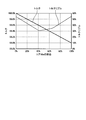
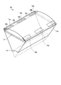
- the perspective view which showed a part of rotor core of Embodiment 1 The figure which showed the result of having calculated the torque and torque ripple with respect to the ratio of the axial direction of the 1st core block in the rotor core of Embodiment 1 with respect to the same electric current.
- FIG. 1 is a cross-sectional view showing a configuration of an embedded permanent magnet electric motor according to the present embodiment
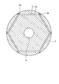
- FIG. 2 is a cross-sectional view of a rotor core according to the present embodiment.
- FIG. 1 and FIG. 2 show a cross-sectional configuration of the first core block among the first and second core blocks constituting the rotor core.
- the embedded permanent magnet electric motor 1 includes an annular stator 2 and a rotor 3 disposed inside the stator 2 in the radial direction via a gap 4.
- the stator 2 includes an annular stator core 5 and windings 7 wound around a plurality of teeth 6 formed on the inner peripheral surface of the stator core 5.
- the teeth 6 are arranged at equal intervals in the circumferential direction of the stator 2 and extend in the radial direction of the stator core 5.
- Winding 7 is distributed. In the distributed winding, the winding 7 is wound over a plurality of teeth 6.
- the rotor 3 includes an annular rotor core 10, a plurality of permanent magnets 11 embedded in the rotor core 10, and a shaft 12 fitted in the center of the rotor core 10.
- the permanent magnet 11 constitutes the magnetic pole of the rotor 3, and the number of magnetic poles is equal to the number of permanent magnets 11.
- the number of permanent magnets 11 is, for example, six, but may be a plurality, and is not limited to six.
- the rotor core 10 has a plurality of magnet insertion holes 13 corresponding to the number of magnetic poles.
- the magnet insertion hole 13 is formed along the circumferential direction of the rotor 3 on the outer peripheral side of the rotor core 10.
- the magnet insertion hole 13 penetrates the rotor core 10 in the axial direction of the rotor core 10.
- the permanent magnet 11 is inserted into the magnet insertion hole 13.
- the permanent magnet 11 has, for example, a flat plate shape, and a main portion 13 c into which the permanent magnet 11 is inserted in the magnet insertion hole 13 extends in a direction orthogonal to the radial direction of the rotor core 10.
- “circumferential direction” refers to the circumferential direction of the rotor core 10
- radial direction refers to the radial direction of the rotor core 10.
- the circumferential direction is also the rotation direction of the rotor 3.
- both end portions in the circumferential direction of the magnet insertion hole 13 become space portions 13 a and 13 b, and space portions 13 a and 13 b are arranged on both sides in the circumferential direction of the permanent magnet 11.
- the magnetization direction of the permanent magnet 11 is the radial direction. Also, the magnetization direction is alternately opposite to the circumferential direction.
- the space portions 13 a and 13 b are bent toward the outer peripheral side with respect to the main portion 13 c into which the permanent magnet 11 is inserted in the magnet insertion hole 13, and extend radially toward the outer peripheral side of the rotor core 10.
- a shaft hole 14 penetrating the rotor core 10 in the axial direction is provided at the center of the rotor core 10, and the shaft 12 is press-fitted into the shaft hole 14.
- a rare earth magnet mainly composed of Nd (neodymium) or Dy (dysprosium) or a ferrite magnet mainly composed of Fe 2 O 3 (iron oxide) is used. It can. Since the rare earth magnet has a high residual magnetic flux density and a coercive force, a permanent magnet embedded type electric motor with high efficiency and improved demagnetization resistance can be configured by using the rare earth magnet. In addition, since the residual magnetic flux density and coercive force of a ferrite magnet are 1/3 that of a rare earth magnet, in order to ensure the same high efficiency and demagnetization resistance as when a rare earth magnet is used, the ferrite magnet to be inserted is used.
- the volume increases beyond the volume of the rare earth magnet, and the ferrite magnet becomes larger.
- ferrite magnets are cheaper and have higher supply stability than rare earth magnets, it is possible to construct an embedded permanent magnet electric motor that is not affected by the cost increase and supply risk of rare earth magnets.
- FIG. 3 is an enlarged cross-sectional view showing a part of the first core block constituting the rotor core of the present embodiment
- FIG. 4 is an enlarged cross-sectional view in which a permanent magnet is inserted into the magnet insertion hole in FIG.
- FIG. 5 is an enlarged sectional view showing a part of the second core block constituting the rotor core of the present embodiment
- FIG. 6 is an enlarged sectional view in which a permanent magnet is inserted into the magnet insertion hole in FIG.
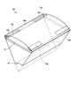
- FIG. 7 is a perspective view showing a part of the rotor core of the present embodiment. 3 to 7, the same components as those shown in FIGS. 1 and 2 are denoted by the same reference numerals.
- FIG. 3 shows a cross-sectional configuration of one magnetic pole of the core block 10a that is the first core block.
- a configuration having an angle range of 60 ° with a central angle based on the rotation center that is the center of the shaft hole 14 is shown.
- FIG. 4 shows a state where the permanent magnet 11 is inserted into the magnet insertion hole 13 in FIG.
- a magnetic pole center 30 that is the center in the circumferential direction of the permanent magnet 11 and an inter-magnetic pole 31 that is the middle between the adjacent magnetic pole centers 30 are also shown.
- an outer edge portion 40 that is a portion of the core block 10 a radially outside the magnet insertion hole 13 is shown.
- FIG. 5 shows a cross-sectional configuration of one magnetic pole of the core block 10b, which is the second core block.
- a configuration having an angle range of 60 ° with a central angle based on the rotation center that is the center of the shaft hole 14 is shown.
- FIG. 6 shows a state where the permanent magnet 11 is inserted into the magnet insertion hole 13 in FIG.
- a magnetic pole center 30 that is the center in the circumferential direction of the permanent magnet 11 and an inter-magnetic pole 31 that is an intermediate between the adjacent magnetic pole centers 30 are also shown.
- the core block 10b is formed with a pair of slits 15a and 15b which are gaps between the magnet insertion hole 13 and the outer peripheral surface of the core block 10b.
- the outer peripheral surface of the core block 10 b is equal to the outer peripheral surface of the rotor core 10.
- the slit 15a is disposed on the outer side in the radial direction with respect to the end portion 11a which is one end portion in the circumferential direction of the permanent magnet 11, and the slit 15b is formed with respect to the end portion 11b which is the other end portion in the circumferential direction of the permanent magnet 11. And arranged outside in the radial direction.
- the slit 15a and the end portion 11a are arranged in the radial direction, and the slit 15b and the end portion 11b are arranged in the radial direction.
- the slit 15a is disposed on the magnetic pole center 30 side adjacent to the space portion 13a
- the slit 15b is disposed on the magnetic pole center 30 side adjacent to the space portion 13b.
- an outer edge portion 41 that is a portion of the core block 10 b that is radially outward from the magnet insertion hole 13 is shown.
- the slits 15 a and 15 b are located at the end of the outer edge portion 41 in the circumferential direction.
- the slit 15a has a rectangular shape extending in the circumferential direction. That is, the length of the slit 15a in the circumferential direction is longer than the length of the slit 15a in the radial direction.
- the slit 15b has a rectangular shape extending in the circumferential direction. That is, the circumferential length of the slit 15b is longer than the radial length of the slit 15b.
- the slits 15a and 15b penetrate the core block 10b in the axial direction.
- the stator 2 shown in FIG. 1 is disposed around the core block 10b.
- the core block 10 a does not have the slits 15 a and 15 b outside the magnet insertion holes 13 in the radial direction of the rotor core 10, whereas the core block 10 b is outside the magnet insertion holes 13 in the radial direction of the rotor core 10.
- FIG. 7 shows the configuration of the rotor core 10 with respect to the angle range for one magnetic pole.
- the rotor core 10 is configured by alternately stacking core blocks 10 a and core blocks 10 b in the axial direction of the rotor core 10.
- the rotor core 10 includes a core block 10a disposed at the center in the axial direction and a pair of core blocks 10b disposed so as to sandwich the core block 10a from both sides in the axial direction.
- One core block 10b of the pair of core blocks 10b constitutes one end face of the rotor core 10
- the other core block 10b of the pair of core blocks 10b constitutes the other end face of the rotor core 10.
- the axial length of the core block 10b is l 2
- the number of laminated magnetic steel sheets constituting the core block 10b is n 2
- l 2 n 2 ⁇ a.
- the axial length of the rotor core 10 is (L 1 + L 2 ), the total axial length of the core block 10 a is L 1 , and the total axial length of the core block 10 b is L 2 .
- the number of stacked layers in the entire rotor core 10 is (N 1 + N 2 ), the number of stacked layers in the core block 10 a is N 1 , and the number of stacked layers in the pair of core blocks 10 b is N 2 .
- the torque ripple is such that the ratio of the total axial length of the core block 10a to the axial length of the rotor core 10 is in the range of 35% to 45%, that is, 0.35 ⁇ L 1 / (L 1 + L 2 ) ⁇ 0.45.
- the torque decreases monotonically as the ratio of the core block 10a increases from 0% to 100%, and when the ratio of the core block 10a is 100%, compared with the case where the ratio of the core block 10a is 0%.
- the torque is reduced by 1.0%.
- the ratio of the core block 10a is in the range of 35% to 45%, the torque reduction can be suppressed to the range of 0.35% to 0.45%.
- the torque ripple when the ratio of the core block 10a is 35% is slightly larger than the torque ripple when the ratio of the core block 10a is 45%, but the torque when the ratio of the core block 10a is 35%
- the torque is slightly larger than the torque when the ratio of the block 10a is 45%. That is, when the ratio of the core block 10a is 35%, the torque ripple is slightly increased compared with the case where the ratio of the core block 10a is 35%, but the torque can be increased correspondingly to improve the motor efficiency. .
- the core block 10a without the slits 15a and 15b and the core block 10b with the slits 15a and 15b are laminated in the axial direction to constitute the rotor core 10.
- the torque acting on the rotor core 10 is given by the combination of the torque acting on the core block 10a and the torque acting on the core block 10b.
- the torque waveform of the torque acting on the core block 10a and the torque waveform of the torque acting on the core block 10b are out of phase, so that the peak value of the torque waveform is canceled in the entire rotor 3.
- the torque ripple of the motor during operation can be reduced.
- the rotor core 10 satisfies 0.35 ⁇ L 1 / (L 1 + L 2 ) ⁇ 0.45 or 0.35 ⁇ N 1 / (N 1 + N 2 ) ⁇ 0.45. By configuring this, it is possible to maximize the torque ripple reduction effect.
- the rotor core 10 is configured by laminating the core block 10 a and the core block 10 b in the axial direction, so that a reduction in torque can be further suppressed.
- the slit 15 a is arranged on the outer side in the radial direction with respect to the end portion 11 a which is one end portion in the circumferential direction of the permanent magnet 11, and the slit 15 b is the other end in the circumferential direction of the permanent magnet 11. It is arrange
- the arrangement of the pair of slits 15a and 15b increases the magnetic resistance between the magnetic poles 31 and reduces the leakage magnetic flux passing through the magnetic poles 31, so that the magnetic flux of the permanent magnet 11 can be used effectively.
- two slits 15a and 15b are provided for each magnetic pole. Thereby, torque can be increased compared with the case where the number of slits is three or more.
- the winding 7 is distributedly wound. Compared with concentrated winding, distributed winding can effectively generate reluctance torque in addition to magnet torque, which is advantageous for increasing torque at the same current, but has a feature that torque ripple due to reluctance torque increases. .
- the highly efficient embedded permanent magnet electric motor 1 can be configured by effectively utilizing the reluctance torque while reducing the torque ripple.
- the winding 7 can also be a concentrated winding.
- the space portions 13a and 13b are provided. Thereby, the short circuit of the magnetic flux in the both ends of the permanent magnet 11 is prevented, the magnetic flux easily passes over the stator 2, and the torque can be increased. In addition, the structure which does not provide the space parts 13a and 13b is also possible.
- the thickness of the electromagnetic steel plates constituting the rotor core 10 is the same, but the thickness may not be the same.
- the core blocks 10a and 10b are each formed by laminating electromagnetic steel plates, they may be integrally formed.
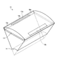
- FIG. 9 is a perspective view showing a part of the rotor core according to the first modification of the present embodiment.
- the rotor core 10 includes a core block 10b disposed in the center in the axial direction and a pair of core blocks 10a disposed so as to sandwich the core block 10b from both sides in the axial direction. It is configured.
- One core block 10 a of the pair of core blocks 10 a constitutes one end face of the rotor core 10
- the other core block 10 a of the pair of core blocks 10 a constitutes the other end face of the rotor core 10. Even in this case, similarly to the present embodiment, it is possible to reduce torque ripple while suppressing a decrease in torque at the same current.
- the torque ripple is obtained by configuring the rotor core 10 so as to satisfy 0.35 ⁇ L 1 / (L 1 + L 2 ) ⁇ 0.45 or 0.35 ⁇ N 2 / (N 1 + N 2 ) ⁇ 0.45.
- the reduction effect can be maximized.
- FIG. 10 is a perspective view showing a part of the rotor core according to the second modification of the present embodiment.
- the rotor core 10 is configured by laminating core blocks 10a and core blocks 10b alternately and in a total of five layers.
- the number of core blocks 10b is 3, and the number of core blocks 10a is 2.
- One core block 10b of the three core blocks 10b constitutes one end face of the rotor core 10, and another one of the three core blocks 10b is the other end face of the rotor core 10.
- the remaining core block 10b of the three core blocks 10b is disposed at the center of the rotor core 10 in the axial direction.
- the torque ripple is obtained by configuring the rotor core 10 so as to satisfy 0.35 ⁇ L 1 / (L 1 + L 2 ) ⁇ 0.45 or 0.35 ⁇ N 2 / (N 1 + N 2 ) ⁇ 0.45. The reduction effect can be maximized.
- the rotor core 10 is not limited to the configuration example of FIG. 7, FIG. 9, or FIG. 10, and can be configured by alternately stacking core blocks 10 a and core blocks 10 b.
- the number of layers may be plural, and may be even or odd.
- the total number of core blocks 10a and core blocks 10b constituting the rotor core 10 may be greater than five layers. Even in this case, similarly to the present embodiment, it is possible to reduce torque ripple while suppressing a decrease in torque at the same current.
- the torque ripple is obtained by configuring the rotor core 10 so as to satisfy 0.35 ⁇ L 1 / (L 1 + L 2 ) ⁇ 0.45 or 0.35 ⁇ N 2 / (N 1 + N 2 ) ⁇ 0.45. The reduction effect can be maximized.
- FIG. FIG. 11 is a diagram illustrating a configuration of the air conditioner according to the present embodiment.
- the air conditioner 100 according to the present embodiment includes an indoor unit 101 and an outdoor unit 102 connected to the indoor unit 101.
- the outdoor unit 102 includes a compressor 103 according to this embodiment.
- the compressor 103 uses the embedded permanent magnet electric motor 1 of the first embodiment. It is assumed that the permanent magnet embedded motor 1 includes the first and second modifications described in the first embodiment.
- the air conditioner 100 is required to have energy saving performance and needs to be highly efficient. Furthermore, in order to suppress the vibration and noise generated from the air conditioner 100 to a reference value or less, it is necessary to reduce the vibration and noise generated from the compressor 103.
- the embedded permanent magnet electric motor 1 of the first embodiment can reduce torque ripple while suppressing torque reduction at the same current. Therefore, by applying the embedded permanent magnet motor 1 to the compressor 103, the compressor 103 and the air conditioner 100 that can reduce vibration and noise caused by torque ripple while suppressing reduction in motor efficiency are configured. Can do.
- the permanent magnet embedded electric motor 1 according to the first embodiment can be applied not only to the compressor 103 but also to the blower 104 of the outdoor unit 102 and the blower 105 of the outdoor unit 102. Even in this case, the same effect as described above can be obtained.
- the permanent magnet embedded electric motor 1 of the first embodiment can be applied to an electric device other than the air conditioner, and in particular, is applied to a compressor of an electric device having a refrigeration cycle other than the air conditioner 100. can do. Even in these cases, the same effect as described above can be obtained.
- the configuration described in the above embodiment shows an example of the contents of the present invention, and can be combined with another known technique, and can be combined with other configurations without departing from the gist of the present invention. It is also possible to omit or change the part.
- 1 Embedded permanent magnet motor 2 stator, 3 rotor, 4 gap, 5 stator core, 6 teeth, 7 windings, 10 rotor core, 10a, 10b core block, 11 permanent magnet, 11a, 11b end, 12 shaft, 13 Magnet insertion hole, 13a, 13b space, 13c main part, 14 shaft hole, 15a, 15b slit, 30 magnetic pole center, 31 between magnetic poles, 40, 41 outer edge, 100 air conditioner, 101 indoor unit, 102 outdoor unit, 103 compressor, 104, 105 blower.
Landscapes
- Engineering & Computer Science (AREA)
- Power Engineering (AREA)
- Physics & Mathematics (AREA)
- Mechanical Engineering (AREA)
- Thermal Sciences (AREA)
- General Engineering & Computer Science (AREA)
- Permanent Field Magnets Of Synchronous Machinery (AREA)
- Iron Core Of Rotating Electric Machines (AREA)
Abstract
永久磁石埋込型電動機のロータ3は、周方向に複数個の磁石挿入孔13が形成された環状のロータコア10と、各磁石挿入孔13に挿入された永久磁石11と、を備え、ロータコア10は、各磁石挿入孔13とロータコア10の外周面との間にスリット15a,15bを有しないコアブロック10aと各磁石挿入孔13とロータコア10の外周面との間にスリット15a,15bを有するコアブロック10bとをロータコア10の軸方向に交互に積層して構成され、スリット15aと永久磁石11の端部11aは径方向に配列され、スリット15bと永久磁石11の端部11bは径方向に配列される。
Description
本発明は、ロータコアに永久磁石が埋め込まれた永久磁石埋込型電動機及び当該永久磁石埋込型電動機を備えた圧縮機に関する。
近年、省エネ意識の高まりから高効率な電動機が要求される様になり、ロータに残留磁束密度及び保磁力の高い希土類磁石を用いることで高効率化を実現した永久磁石埋込型電動機が多く提案されている。さらに、永久磁石をロータ内部に埋め込んだ構造とすることで、マグネットトルクだけではなくリラクタンストルクを利用することができるため、高効率な電動機が構成可能となる。リラクタンストルクはd軸とq軸のインダクタンスの差に比例するため、リラクタンストルクを向上させるためには、一般的にはq軸磁束を通し易く、かつ、d軸磁束を通しにくい構造が望ましい。ここで、d軸は磁石中央を通る径方向の軸であり、q軸はd軸を電気角で90°回転させた軸である。
しかし、リラクタンストルクを利用しない永久磁石埋込型電動機と比較し、リラクタンストルクの利用率が高い永久磁石埋込型電動機ではトルク波形に脈動が生じやすく、トルクリプルが増大する課題がある。永久磁石埋込型電動機において運転中のトルクリプルは振動及び騒音の原因となるため、基準値以内に抑制する必要がある。
特許文献1では、永久磁石埋込型電動機のロータ表面に複数のスリットを配置することでトルクリプルが低減されることが記載されている。
しかしながら、特許文献1に記載された永久磁石埋込型電動機では、ロータ表面に複数のスリットを配置することでトルクリプルの低減は可能であるものの、スリットが磁束の磁路を妨げてしまうため、同一電流におけるトルクが低減する。この場合、同一トルクを発生させるために必要な電流が大きくなるため、銅損増加により電動機効率の低下を招く。
本発明は、上記に鑑みてなされたものであって、同一電流におけるトルクの低下を抑制して電動機効率を維持すると共にトルクリプルを低減可能な永久磁石埋込型電動機を提供することを目的とする。
上述した課題を解決し、目的を達成するために、本発明に係る永久磁石埋込型電動機は、周方向に沿って複数個の磁石挿入孔が形成された環状のロータコアと、前記複数個の磁石挿入孔にそれぞれ挿入された複数個の永久磁石と、を備え、前記ロータコアは、前記ロータコアの径方向における前記各磁石挿入孔の外側にスリットを有しない第1のコアブロックと前記ロータコアの径方向における前記各磁石挿入孔の外側に一対のスリットを有する第2のコアブロックとを当該ロータコアの軸方向に交互に積層して構成され、前記一対のスリットの一方と前記各永久磁石の前記周方向の一端部は、前記ロータコアの径方向に配列され、前記一対のスリットの他方と前記各永久磁石の前記周方向の他端部は、前記ロータコアの径方向に配列される。
本発明によれば、同一電流におけるトルクの低下を抑制して電動機効率を維持すると共にトルクリプルを低減することができる、という効果を奏する。
以下に、本発明の実施の形態に係る永久磁石埋込型電動機及び圧縮機を図面に基づいて詳細に説明する。なお、この実施の形態によりこの発明が限定されるものではない。
実施の形態1.
図1は、本実施の形態に係る永久磁石埋込型電動機の構成を示す断面図、図2は、本実施の形態のロータコアの断面図である。後述するように、図1及び図2は、ロータコアを構成する第1及び第2のコアブロックのうち第1のコアブロックにおける断面構成を示したものである。
図1は、本実施の形態に係る永久磁石埋込型電動機の構成を示す断面図、図2は、本実施の形態のロータコアの断面図である。後述するように、図1及び図2は、ロータコアを構成する第1及び第2のコアブロックのうち第1のコアブロックにおける断面構成を示したものである。
永久磁石埋込型電動機1は、環状のステータ2と、ステータ2の径方向の内側に空隙4を介して配置されたロータ3とを備えている。
ステータ2は、環状のステータコア5と、ステータコア5の内周面に形成された複数個のティース6に巻回された巻線7とを備えている。ティース6は、ステータ2の周方向に等間隔で配置され、ステータコア5の径方向に伸びている。
巻線7は分布巻されている。分布巻では、巻線7が複数個のティース6にわたって巻回される。
ロータ3は、円環状のロータコア10と、ロータコア10に埋め込まれた複数個の永久磁石11と、ロータコア10の中央に嵌め込まれたシャフト12とを備えている。永久磁石11はロータ3の磁極を構成し、磁極数は永久磁石11の個数に等しい。永久磁石11の個数は例えば6個としているが、複数個であればよく6個に限定されない。
ロータコア10には、磁極数の数だけ複数個の磁石挿入孔13が形成されている。磁石挿入孔13は、ロータコア10の外周側でロータ3の周方向に沿って形成されている。磁石挿入孔13は、ロータコア10の軸方向にロータコア10を貫通する。磁石挿入孔13には永久磁石11が挿入される。永久磁石11は例えば平板状であり、磁石挿入孔13のうち永久磁石11が挿入される主要部13cはロータコア10の径方向と直交する方向に伸びている。なお、以下では、「周方向」とはロータコア10の周方向をいい、「径方向」とはロータコア10の径方向をいう。周方向は、ロータ3の回転方向でもある。
また、磁石挿入孔13の周方向の両端部は空間部13a,13bとなり、永久磁石11の周方向の両側には空間部13a,13bが配置される。永久磁石11の着磁方向は径方向である。また、着磁方向は周方向に交互に逆方向となる。空間部13a,13bは、磁石挿入孔13のうち永久磁石11が挿入される主要部13cに対して外周側に折れ曲がり、ロータコア10の外周側に向かって径方向に伸びている。ロータコア10の中央にはロータコア10を軸方向に貫通するシャフト穴14が設けられ、シャフト穴14にはシャフト12が圧入される。
磁石挿入孔13に挿入される永久磁石11には、Nd(ネオジム)若しくはDy(ジスプロシウム)を主成分とした希土類磁石又はFe2O3(酸化鉄)を主成分としたフェライト磁石を用いることができる。希土類磁石は高い残留磁束密度と保磁力を有するため、希土類磁石を用いることで高効率でかつ減磁耐力が向上した永久磁石埋込型電動機を構成することができる。また、フェライト磁石は残留磁束密度と保磁力が希土類磁石の1/3であるため、希土類磁石を用いる場合と同様の高効率性及び減磁耐力を確保するためには、挿入されるフェライト磁石の体積が希土類磁石の体積よりも増大し、フェライト磁石が大型化する。しかしながら、フェライト磁石は希土類磁石よりも安価で供給安定性が高いため、希土類磁石のコストアップ及び供給リスクの影響を受けない永久磁石埋込型電動機を構成することができる。
図3は、本実施の形態のロータコアを構成する第1のコアブロックの一部を示した拡大断面図、図4は、図3において磁石挿入孔に永久磁石が挿入された拡大断面図である。図5は、本実施の形態のロータコアを構成する第2のコアブロックの一部を示した拡大断面図、図6は、図5において磁石挿入孔に永久磁石が挿入された拡大断面図である。図7は、本実施の形態のロータコアの一部を示した斜視図である。なお、図3から図7では、図1及び図2に示す構成要素と同一の構成要素には同一の符号を付している。
図3では、第1のコアブロックであるコアブロック10aの一磁極分の断面構成が示されている。具体的には、図2で示す断面構成のうちシャフト穴14の中心である回転中心を基準にした中心角で60°の角度範囲の構成が示されている。図4は、図3において磁石挿入孔13に永久磁石11が挿入された状態を示している。なお、図4では、永久磁石11の周方向の中心である磁極中心30と、隣り合う磁極中心30の中間である磁極間31を併せて示している。なお、図4では、磁石挿入孔13よりも径方向の外側のコアブロック10aの部分である外縁部40が示されている。
図5では、第2のコアブロックであるコアブロック10bの一磁極分の断面構成が示されている。具体的には、図2で示す断面構成のうちシャフト穴14の中心である回転中心を基準にした中心角で60°の角度範囲の構成が示されている。図6は、図5において磁石挿入孔13に永久磁石11が挿入された状態を示している。なお、図6では、永久磁石11の周方向の中心である磁極中心30と、隣り合う磁極中心30の中間である磁極間31を併せて示している。
図5及び図6に示すように、コアブロック10bには、磁石挿入孔13とコアブロック10bの外周面との間に空隙である一対のスリット15a,15bが形成されている。ここで、コアブロック10bの外周面はロータコア10の外周面に等しい。スリット15aは、永久磁石11の周方向の一端部である端部11aに対して径方向の外側に配置され、スリット15bは、永久磁石11の周方向の他端部である端部11bに対して径方向の外側に配置されている。すなわち、スリット15aと端部11aは径方向に配列され、スリット15bと端部11bは径方向に配列される。また、スリット15aは、空間部13aに隣接して磁極中心30側に配置され、スリット15bは、空間部13bに隣接して磁極中心30側に配置されている。なお、図6では、磁石挿入孔13よりも径方向の外側のコアブロック10bの部分である外縁部41が示されている。スリット15a,15bは、外縁部41の周方向の端部に位置している。
スリット15aは、周方向に伸びる矩形状である。すなわち、スリット15aの周方向の長さはスリット15aの径方向の長さよりも長い。スリット15bは、周方向に伸びる矩形状である。すなわち、スリット15bの周方向の長さはスリット15bの径方向の長さよりも長い。スリット15a,15bは、コアブロック10bを軸方向に貫通している。
コアブロック10bの他の構成はコアブロック10aの構成と同じである。また、永久磁石埋込型電動機1では、コアブロック10bの周囲には図1のステータ2が配置される。
このように、コアブロック10aはロータコア10の径方向における各磁石挿入孔13の外側にスリット15a,15bを有しないのに対し、コアブロック10bはロータコア10の径方向における各磁石挿入孔13の外側にスリット15a,15bを有する。
図7では、一磁極分の角度範囲に対してロータコア10の構成を示している。図7に示すように、ロータコア10は、コアブロック10aとコアブロック10bとがロータコア10の軸方向に交互に積層して構成される。具体的には、ロータコア10は、軸方向の中央に配置されたコアブロック10aと、コアブロック10aを軸方向の両側から挟むようにして配置された一対のコアブロック10bとで構成されている。一対のコアブロック10bのうちの一方のコアブロック10bはロータコア10の一方の端面を構成し、一対のコアブロック10bのうちの他方のコアブロック10bはロータコア10の他方の端面を構成する。
コアブロック10aは、電磁鋼板を図3に示すように打ち抜き、打ち抜かれた電磁鋼板を複数枚かしめながら積層して形成される。電磁鋼板の板厚をa、コアブロック10aの軸方向の長さをl1、コアブロック10aを構成する電磁鋼板の積層枚数をn1とすると、l1=n1×aである。同様に、コアブロック10bは、電磁鋼板を図5に示すように打ち抜き、打ち抜かれた電磁鋼板を複数枚かしめながら積層して形成される。電磁鋼板の板厚をa、コアブロック10bの軸方向の長さをl2、コアブロック10bを構成する電磁鋼板の積層枚数をn2とすると、l2=n2×aである。コアブロック10aの軸方向の全長は、L1=(l1+l1)=2n1×a=N1×aで与えられる。ここで、N1=2n1は、コアブロック10aを構成する電磁鋼板の積層枚数の合計である。また、コアブロック10bの軸方向の全長は、L2=n2×a=N2×aで与えられる。ここで、N2=n2はコアブロック10bを構成する電磁鋼板の積層枚数の合計である。
このように、ロータコア10の軸方向の長さは(L1+L2)、コアブロック10aの軸方向の全長はL1、コアブロック10bの軸方向の全長はL2である。また、ロータコア10全体での積層枚数は(N1+N2)、コアブロック10aでの積層枚数はN1、一対のコアブロック10bでの積層枚数はN2である。
図8は、本実施の形態のロータコアにおける第1のコアブロックの軸方向の割合に対するトルク及びトルクリプルを同一電流に対して算出した結果を示した図である。すなわち、横軸は、L1/(L1+L2)であり、ロータコア10の軸方向の長さに対するコアブロック10aの軸方向の全長の割合である。L1/(L1+L2)=N1/(N1+N2)であるから、横軸はロータコア10全体での積層枚数に対するコアブロック10aでの積層枚数の合計の割合でもある。縦軸はトルク又はトルクリプルである。
図8に示すように、トルクリプルは、ロータコア10の軸方向の長さに対するコアブロック10aの軸方向の全長の割合が35%から45%の範囲内、すなわち、0.35≦L1/(L1+L2)≦0.45の範囲内に最小値を有する。
一方、トルクはコアブロック10aの割合が0%から100%に増大するにつれて単調に減少し、コアブロック10aの割合が0%の場合と比較して、コアブロック10aの割合が100%の場合は、トルクは1.0%低下する。これに対し、コアブロック10aの割合が35%から45%までの範囲では、トルクの低下を0.35%から0.45%までの範囲に抑えることができる。
なお、コアブロック10aの割合が35%の場合のトルクリプルは、コアブロック10aの割合が45%の場合のトルクリプルよりもわずかに大きいが、コアブロック10aの割合が35%の場合のトルクは、コアブロック10aの割合が45%の場合のトルクよりもわずかに大きい。つまり、コアブロック10aの割合が35%の場合は、コアブロック10aの割合が35%の場合に比べて、トルクリプルがわずかに増大するもののその分トルクを増大させて電動機効率を向上させることができる。
本実施の形態では、スリット15a,15bを設けないコアブロック10aとスリット15a,15bを設けたコアブロック10bを軸方向に積層してロータコア10を構成している。この構成では、ロータコア10に作用するトルクはコアブロック10aに作用するトルクとコアブロック10bに作用するトルクの合成で与えられる。この場合、スリット15a,15bの効果により、コアブロック10aに作用するトルクのトルク波形とコアブロック10bに作用するトルクのトルク波形の位相がずれるので、ロータ3全体ではトルク波形のピーク値が相殺されることになり、運転中の電動機のトルクリプルを低減することが可能となる。
また、図8に示すように、0.35≦L1/(L1+L2)≦0.45又は0.35≦N1/(N1+N2)≦0.45を満たす様にロータコア10を構成することで、トルクリプルの低減効果を最大限に高めることができる。
さらに、図8に示すように、ロータコア10をコアブロック10aとコアブロック10bを軸方向に積層して構成することで、トルクの低下をより抑制することができる。
また、本実施の形態では、スリット15aは、永久磁石11の周方向の一端部である端部11aに対して径方向の外側に配置され、スリット15bは、永久磁石11の周方向の他端部である端部11bに対して径方向の外側に配置されている。すなわち、スリット15aと端部11aは径方向に配列され、スリット15bと端部11bは径方向に配列される。このような一対のスリット15a,15bの配置により、磁極間31での磁気抵抗が大きくなり、磁極間31を通過する漏れ磁束が減るため、永久磁石11の磁束を有効に利用することができる。
また、本実施の形態では、一磁極当たり2個のスリット15a,15bを設けている。これにより、スリット数を3個以上にする場合に比べて、トルクを増大させることができる。
なお、コアブロック10bに設ける一磁極当たりのスリット数を1又は3以上とする構成も可能である。また、コアブロック10bに設けるスリットの位置、形状及び大きさは図示例に限定されない。すなわち、コアブロック10bにスリットを設けることにより、程度の差はあれ同様のトルクリプルの低減効果を得ることができる。
以上のように、本実施の形態によれば、同一電流におけるトルクの低下を抑制して電動機効率を維持すると共にトルクリプルを低減することができる。
また、本実施の形態では、巻線7は分布巻されている。分布巻は集中巻と比較し、マグネットトルクに加えてリラクタンストルクを有効に発生させることができるため、同一電流におけるトルクの増加に有利である反面、リラクタンストルクに起因するトルクリプルが増大する特徴がある。本実施の形態のロータ3を分布巻のステータ2に適用することで、トルクリプルを低減しつつリラクタンストルクを有効利用して高効率な永久磁石埋込型電動機1を構成することができる。なお、巻線7は集中巻とすることもできる。
また、本実施の形態では、空間部13a,13bを設けている。これにより、永久磁石11の両端部での磁束の短絡が防止され、磁束がステータ2に渡り易くなり、トルクを大きくすることができる。なお、空間部13a,13bを設けない構成も可能である。
また、本実施の形態では、ロータコア10を構成する電磁鋼板の板厚は同一であるとしたが、板厚は同一でなくてもよい。また、コアブロック10a,10bはそれぞれ電磁鋼板を積層して形成したが、一体で形成されてもよい。
図9は、本実施の形態の変形例1に係るロータコアの一部を示した斜視図である。図9に示すように、本変形例では、ロータコア10は、軸方向の中央に配置されたコアブロック10bと、コアブロック10bを軸方向の両側から挟むようにして配置された一対のコアブロック10aとで構成されている。一対のコアブロック10aのうちの一方のコアブロック10aはロータコア10の一方の端面を構成し、一対のコアブロック10aのうちの他方のコアブロック10aはロータコア10の他方の端面を構成する。この場合でも、本実施の形態と同様に、同一電流におけるトルクの低下を抑制しつつ、トルクリプルの低減が可能になる。特に、0.35≦L1/(L1+L2)≦0.45又は0.35≦N2/(N1+N2)≦0.45を満たす様にロータコア10を構成することで、トルクリプルの低減効果を最大限に高めることができる。
図10は、本実施の形態の変形例2に係るロータコアの一部を示した斜視図である。図10に示すように、本変形例では、ロータコア10は、コアブロック10aとコアブロック10bとを交互にかつ全体で5層となるように積層して構成される。図示例では、コアブロック10bの個数が3、コアブロック10aの個数が2である。3個のコアブロック10bのうちの1個のコアブロック10bはロータコア10の一方の端面を構成し、3個のコアブロック10bのうちの別の1個のコアブロック10bはロータコア10の他方の端面を構成し、3個のコアブロック10bのうちの残りのコアブロック10bはロータコア10の軸方向の中央に配置される。この場合でも、本実施の形態と同様に、同一電流におけるトルクの低下を抑制しつつ、トルクリプルの低減が可能になる。特に、0.35≦L1/(L1+L2)≦0.45又は0.35≦N2/(N1+N2)≦0.45を満たす様にロータコア10を構成することで、トルクリプルの低減効果を最大限に高めることができる。
なお、ロータコア10は、図7、図9又は図10の構成例に限定されず、コアブロック10aとコアブロック10bとを交互に積層して構成することができる。積層数は複数であればよく、偶数又は奇数のいずれでもよい。ロータコア10を構成するコアブロック10aとコアブロック10bの合計数は5層よりも多くしてもよい。この場合でも、本実施の形態と同様に、同一電流におけるトルクの低下を抑制しつつ、トルクリプルの低減が可能になる。特に、0.35≦L1/(L1+L2)≦0.45又は0.35≦N2/(N1+N2)≦0.45を満たす様にロータコア10を構成することで、トルクリプルの低減効果を最大限に高めることができる。
実施の形態2.
図11は、本実施の形態に係る空気調和機の構成を示す図である。本実施の形態に係る空気調和機100は、室内機101と、室内機101に接続される室外機102とを備える。室外機102は、本実施の形態に係る圧縮機103を備える。圧縮機103には、実施の形態1の永久磁石埋込型電動機1が使用されている。なお、永久磁石埋込型電動機1には、実施の形態1で説明した変形例1,2が含まれるものとする。
図11は、本実施の形態に係る空気調和機の構成を示す図である。本実施の形態に係る空気調和機100は、室内機101と、室内機101に接続される室外機102とを備える。室外機102は、本実施の形態に係る圧縮機103を備える。圧縮機103には、実施の形態1の永久磁石埋込型電動機1が使用されている。なお、永久磁石埋込型電動機1には、実施の形態1で説明した変形例1,2が含まれるものとする。
空気調和機100は省エネ性能が要求されており、高効率である必要がある。さらに、空気調和機100から発生する振動及び騒音を基準値以下に抑えるために、圧縮機103から発生する振動及び騒音を低減する必要がある。実施の形態1の永久磁石埋込型電動機1は、同一電流におけるトルクの低減を抑えつつトルクリプルを低減することができる。従って、永久磁石埋込型電動機1を圧縮機103に適用することで、電動機効率の低減を抑えながらもトルクリプルに起因する振動及び騒音を低減可能な圧縮機103及び空気調和機100を構成することができる。
なお、実施の形態1の永久磁石埋込型電動機1は、圧縮機103のみならず、室外機102の送風機104及び室外機102の送風機105にそれぞれ適用することもできる。この場合でも、上記と同様の効果が得られる。
また、実施の形態1の永久磁石埋込型電動機1は、空気調和機以外の電気機器に適用することもでき、特に、空気調和機100以外の冷凍サイクルを備えた電気機器の圧縮機に適用することができる。これらの場合でも、上記と同様の効果が得られる。
以上の実施の形態に示した構成は、本発明の内容の一例を示すものであり、別の公知の技術と組み合わせることも可能であるし、本発明の要旨を逸脱しない範囲で、構成の一部を省略、変更することも可能である。
1 永久磁石埋込型電動機、2 ステータ、3 ロータ、4 空隙、5 ステータコア、6 ティース、7 巻線、10 ロータコア、10a,10b コアブロック、11 永久磁石、11a,11b 端部、12 シャフト、13 磁石挿入孔、13a,13b 空間部、13c 主要部、14 シャフト穴、15a,15b スリット、30 磁極中心、31 磁極間、40,41 外縁部、100 空気調和機、101 室内機、102 室外機、103 圧縮機、104,105 送風機。
Claims (6)
- 周方向に沿って複数個の磁石挿入孔が形成された環状のロータコアと、
前記複数個の磁石挿入孔にそれぞれ挿入された複数個の永久磁石と、
を備え、
前記ロータコアは、前記ロータコアの径方向における前記各磁石挿入孔の外側にスリットを有しない第1のコアブロックと前記ロータコアの径方向における前記各磁石挿入孔の外側に一対のスリットを有する第2のコアブロックとを当該ロータコアの軸方向に交互に積層して構成され、
前記一対のスリットの一方と前記各永久磁石の前記周方向の一端部は、前記ロータコアの径方向に配列され、前記一対のスリットの他方と前記各永久磁石の前記周方向の他端部は、前記ロータコアの径方向に配列される永久磁石埋込型電動機。 - 前記ロータコアの前記軸方向の長さに対する前記第1のコアブロックの前記軸方向の全長の割合が0.35以上かつ0.45以下である請求項1に記載の永久磁石埋込型電動機。
- 前記第1及び第2のコアブロックは板厚が同一の電磁鋼板を積層して構成され、
前記第1のコアブロックを構成する電磁鋼板の積層枚数の合計をN1、前記第2のコアブロックを構成する電磁鋼板の積層枚数の合計をN2とした場合に、0.35≦N1/(N1+N2)≦0.45である請求項2に記載の永久磁石埋込型電動機。 - 前記スリットは、前記周方向の長さが前記径方向の長さよりも長い矩形状である請求項1から3のいずれか1項に記載の永久磁石埋込型電動機。
- 巻線が巻回された複数個のティースを有する環状のステータを備え、
前記巻線は、前記複数個のティースに分布巻されている請求項1から4のいずれか1項に記載の永久磁石埋込型電動機。 - 請求項1から5のいずれか1項に記載の永久磁石埋込型電動機を備えた圧縮機。
Priority Applications (5)
| Application Number | Priority Date | Filing Date | Title |
|---|---|---|---|
| PCT/JP2015/067205 WO2016203530A1 (ja) | 2015-06-15 | 2015-06-15 | 永久磁石埋込型電動機及び圧縮機 |
| CN201580079297.8A CN107534335B (zh) | 2015-06-15 | 2015-06-15 | 转子、永久磁铁埋入型电动机、压缩机以及空气调节机 |
| JP2017524166A JP6442054B2 (ja) | 2015-06-15 | 2015-06-15 | ロータ、永久磁石埋込型電動機、圧縮機及び空気調和機 |
| EP15895551.8A EP3309931B1 (en) | 2015-06-15 | 2015-06-15 | Permanent magnet-embedded motor and compressor |
| US15/557,587 US10581286B2 (en) | 2015-06-15 | 2015-06-15 | Permanent-magnet-embedded electric motor and compressor |
Applications Claiming Priority (1)
| Application Number | Priority Date | Filing Date | Title |
|---|---|---|---|
| PCT/JP2015/067205 WO2016203530A1 (ja) | 2015-06-15 | 2015-06-15 | 永久磁石埋込型電動機及び圧縮機 |
Publications (1)
| Publication Number | Publication Date |
|---|---|
| WO2016203530A1 true WO2016203530A1 (ja) | 2016-12-22 |
Family
ID=57545444
Family Applications (1)
| Application Number | Title | Priority Date | Filing Date |
|---|---|---|---|
| PCT/JP2015/067205 Ceased WO2016203530A1 (ja) | 2015-06-15 | 2015-06-15 | 永久磁石埋込型電動機及び圧縮機 |
Country Status (5)
| Country | Link |
|---|---|
| US (1) | US10581286B2 (ja) |
| EP (1) | EP3309931B1 (ja) |
| JP (1) | JP6442054B2 (ja) |
| CN (1) | CN107534335B (ja) |
| WO (1) | WO2016203530A1 (ja) |
Cited By (1)
| Publication number | Priority date | Publication date | Assignee | Title |
|---|---|---|---|---|
| WO2019215865A1 (ja) * | 2018-05-10 | 2019-11-14 | 三菱電機株式会社 | ロータ、電動機、圧縮機および空気調和装置 |
Families Citing this family (3)
| Publication number | Priority date | Publication date | Assignee | Title |
|---|---|---|---|---|
| US20220376569A1 (en) * | 2020-02-12 | 2022-11-24 | Mitsubishi Electric Corporation | Rotor, motor, fan, and air conditioner |
| JP7459155B2 (ja) * | 2022-03-07 | 2024-04-01 | 三菱電機株式会社 | 回転電機及びその界磁子製造方法 |
| EP4503390A4 (en) * | 2022-03-29 | 2025-11-05 | Toshiba Kk | INTEGRATED MAGNET ROTOR AND ROTATING ELECTRIC MACHINE |
Citations (4)
| Publication number | Priority date | Publication date | Assignee | Title |
|---|---|---|---|---|
| JP2009106001A (ja) * | 2007-10-19 | 2009-05-14 | Toyota Motor Corp | 回転電機 |
| JP2009219291A (ja) * | 2008-03-12 | 2009-09-24 | Mitsubishi Electric Corp | 同期電動機の回転子及び圧縮機 |
| WO2013114542A1 (ja) * | 2012-01-30 | 2013-08-08 | 三菱電機株式会社 | 永久磁石埋込型電動機の回転子、及びこの回転子を備えた電動機、及びこの電動機を備えた圧縮機、及びこの圧縮機を備えた空気調和機 |
| JP5414900B2 (ja) * | 2010-08-27 | 2014-02-12 | 三菱電機株式会社 | 永久磁石埋込型モータの回転子及び圧縮機及び冷凍空調装置 |
Family Cites Families (9)
| Publication number | Priority date | Publication date | Assignee | Title |
|---|---|---|---|---|
| JP3490307B2 (ja) | 1998-09-29 | 2004-01-26 | 三菱電機株式会社 | 永久磁石型モータ |
| JP3722126B2 (ja) | 2003-01-31 | 2005-11-30 | 松下電器産業株式会社 | リラクタンスモータ |
| JP4793249B2 (ja) * | 2006-04-20 | 2011-10-12 | 株式会社豊田自動織機 | 永久磁石埋設型回転電機及びカーエアコン用モータ並びに密閉型電動圧縮機 |
| EP2536003B1 (en) * | 2010-02-08 | 2018-01-17 | Mitsubishi Electric Corporation | Rotor of permanent magnet embedded motor, blower, and compressor |
| CN103891102B (zh) * | 2011-10-24 | 2016-08-24 | 三菱电机株式会社 | 永久磁铁嵌入式电动机的转子、压缩机和制冷空调装置 |
| JP2014079068A (ja) | 2012-10-10 | 2014-05-01 | Daikin Ind Ltd | ロータコア及びその製造方法 |
| DE102013113657A1 (de) * | 2012-12-07 | 2014-06-12 | Denso Corporation | Rotierende elektrische Maschine in Mehrfach-Luftspalt-Ausführung |
| JP5930994B2 (ja) * | 2013-03-22 | 2016-06-08 | 三菱電機株式会社 | 永久磁石埋込型電動機の回転子、圧縮機及び冷凍空調装置 |
| CN203554102U (zh) * | 2013-11-12 | 2014-04-16 | 中山大洋电机股份有限公司 | 一种减小面贴式永磁转子转矩脉动的永磁电机结构 |
-
2015
- 2015-06-15 US US15/557,587 patent/US10581286B2/en active Active
- 2015-06-15 WO PCT/JP2015/067205 patent/WO2016203530A1/ja not_active Ceased
- 2015-06-15 EP EP15895551.8A patent/EP3309931B1/en active Active
- 2015-06-15 JP JP2017524166A patent/JP6442054B2/ja not_active Expired - Fee Related
- 2015-06-15 CN CN201580079297.8A patent/CN107534335B/zh not_active Expired - Fee Related
Patent Citations (4)
| Publication number | Priority date | Publication date | Assignee | Title |
|---|---|---|---|---|
| JP2009106001A (ja) * | 2007-10-19 | 2009-05-14 | Toyota Motor Corp | 回転電機 |
| JP2009219291A (ja) * | 2008-03-12 | 2009-09-24 | Mitsubishi Electric Corp | 同期電動機の回転子及び圧縮機 |
| JP5414900B2 (ja) * | 2010-08-27 | 2014-02-12 | 三菱電機株式会社 | 永久磁石埋込型モータの回転子及び圧縮機及び冷凍空調装置 |
| WO2013114542A1 (ja) * | 2012-01-30 | 2013-08-08 | 三菱電機株式会社 | 永久磁石埋込型電動機の回転子、及びこの回転子を備えた電動機、及びこの電動機を備えた圧縮機、及びこの圧縮機を備えた空気調和機 |
Cited By (3)
| Publication number | Priority date | Publication date | Assignee | Title |
|---|---|---|---|---|
| WO2019215865A1 (ja) * | 2018-05-10 | 2019-11-14 | 三菱電機株式会社 | ロータ、電動機、圧縮機および空気調和装置 |
| JPWO2019215865A1 (ja) * | 2018-05-10 | 2020-12-10 | 三菱電機株式会社 | ロータ、電動機、圧縮機および空気調和装置 |
| US11831204B2 (en) | 2018-05-10 | 2023-11-28 | Mitsubishi Electric Corporation | Rotor, motor, compressor, and air conditioner |
Also Published As
| Publication number | Publication date |
|---|---|
| EP3309931A1 (en) | 2018-04-18 |
| JPWO2016203530A1 (ja) | 2017-09-07 |
| EP3309931A4 (en) | 2019-01-09 |
| EP3309931B1 (en) | 2021-07-21 |
| CN107534335A (zh) | 2018-01-02 |
| US20180062462A1 (en) | 2018-03-01 |
| US10581286B2 (en) | 2020-03-03 |
| CN107534335B (zh) | 2020-02-28 |
| JP6442054B2 (ja) | 2018-12-19 |
Similar Documents
| Publication | Publication Date | Title |
|---|---|---|
| JP5933743B2 (ja) | 永久磁石埋込型電動機、圧縮機、および冷凍空調装置 | |
| CN104823357B (zh) | 永磁体埋入型电动机及具有该永磁体埋入型电动机的冷冻空调装置 | |
| JP5889340B2 (ja) | 永久磁石埋込型電動機の回転子、及びこの回転子を備えた電動機、及びこの電動機を備えた圧縮機、及びこの圧縮機を備えた空気調和機 | |
| JP5538439B2 (ja) | 永久磁石埋込型モータの回転子及び送風機及び圧縮機 | |
| CN103907267B (zh) | 永久磁铁嵌入型电动机的转子、电动机、压缩机和空调机 | |
| JP5921685B2 (ja) | 永久磁石埋込型電動機、圧縮機、及び冷凍空調装置 | |
| WO2017085814A1 (ja) | 電動機および空気調和機 | |
| US10069365B2 (en) | Three-phase electromagnetic motor with 8*n permanent magnet rotor and 6*n magnetic pole stator with 3*n windings around every other magnetic pole | |
| JP2010206882A (ja) | 電動機及び圧縮機及び空気調和機及び電気掃除機 | |
| JP2012050331A (ja) | 電動機 | |
| JP2013059262A (ja) | 固定子鉄心及び固定子及び電動機及び圧縮機 | |
| KR102492064B1 (ko) | 계자 권선형 모터용 로터 | |
| JP6442054B2 (ja) | ロータ、永久磁石埋込型電動機、圧縮機及び空気調和機 | |
| CN203896058U (zh) | 永磁式旋转电机及电梯驱动提升机 | |
| JP2010200480A (ja) | 埋め込み磁石式モータ | |
| KR20200143729A (ko) | 회전자, 모터와 압축기 | |
| US10374474B2 (en) | Permanent magnet motor | |
| JP5863694B2 (ja) | 永久磁石埋込型電動機、圧縮機及び冷凍空調装置 | |
| CN104600937B (zh) | 同步磁阻电机 | |
| KR101628150B1 (ko) | 계자권선형 구동모터의 회전자 | |
| CN102769366B (zh) | 永磁辅助同步磁阻电机和电机安装方法及具有其的压缩机 |
Legal Events
| Date | Code | Title | Description |
|---|---|---|---|
| 121 | Ep: the epo has been informed by wipo that ep was designated in this application |
Ref document number: 15895551 Country of ref document: EP Kind code of ref document: A1 |
|
| ENP | Entry into the national phase |
Ref document number: 2017524166 Country of ref document: JP Kind code of ref document: A |
|
| WWE | Wipo information: entry into national phase |
Ref document number: 15557587 Country of ref document: US |
|
| NENP | Non-entry into the national phase |
Ref country code: DE |