WO2016203753A1 - Dispositif et procédé de détection de bruit, dispositif et procédé de suppression de bruit et support d'enregistrement - Google Patents
Dispositif et procédé de détection de bruit, dispositif et procédé de suppression de bruit et support d'enregistrement Download PDFInfo
- Publication number
- WO2016203753A1 WO2016203753A1 PCT/JP2016/002839 JP2016002839W WO2016203753A1 WO 2016203753 A1 WO2016203753 A1 WO 2016203753A1 JP 2016002839 W JP2016002839 W JP 2016002839W WO 2016203753 A1 WO2016203753 A1 WO 2016203753A1
- Authority
- WO
- WIPO (PCT)
- Prior art keywords
- section
- frame
- impact sound
- signal
- feature amount
- Prior art date
- Legal status (The legal status is an assumption and is not a legal conclusion. Google has not performed a legal analysis and makes no representation as to the accuracy of the status listed.)
- Ceased
Links
Images






Classifications
-
- G—PHYSICS
- G10—MUSICAL INSTRUMENTS; ACOUSTICS
- G10L—SPEECH ANALYSIS TECHNIQUES OR SPEECH SYNTHESIS; SPEECH RECOGNITION; SPEECH OR VOICE PROCESSING TECHNIQUES; SPEECH OR AUDIO CODING OR DECODING
- G10L21/00—Speech or voice signal processing techniques to produce another audible or non-audible signal, e.g. visual or tactile, in order to modify its quality or its intelligibility
- G10L21/02—Speech enhancement, e.g. noise reduction or echo cancellation
- G10L21/0208—Noise filtering
- G10L21/0216—Noise filtering characterised by the method used for estimating noise
- G10L21/0232—Processing in the frequency domain
Definitions
- the present invention relates to a noise detection device, a noise suppression device, a noise detection method, a noise suppression method, and a recording medium.
- Patent Document 1 and Non-Patent Document 1 describe a technique for determining whether or not there is a sudden noise, and reducing the sudden noise if it exists.
- Patent Document 2 describes that the presence of a sudden change in the input signal is determined based on the linearity of the phase component signal in the frequency domain.
- Patent Document 3 describes that audio information is extracted from reproduction information including music information.
- Patent Document 4 An example of improving the quality of voice is described in Patent Document 4, for example.
- Sudden noise is, for example, an impact sound.
- the impact sound is a sound generated when an object collides with the object, an explosion sound, or a sound generated when an instantaneous and sudden force is applied to the object.
- noise reduction processing noise suppression processing
- the present invention has been made in view of the above problems, and an object of the present invention is to provide a technique for more suitably detecting an impact sound section from an acoustic signal.
- the noise detection device calculates, from an acoustic signal including an impact sound, a feature amount representing a steep change in the acoustic signal for each frame obtained by dividing the acoustic signal into a predetermined time length.
- Calculating means for detecting, as a start time of an impact sound section in which the impact sound is present, a frame in which a signal change is sharper than an audio signal based on the feature amount;
- Second detection means for detecting, based on the feature amount, the last frame among the frames having a greater signal steepness than the audio signal continuously from the start time as the end time of the impact sound section; .
- the noise suppression device is an acoustic signal including a shock sound, the first section of the shock sound, the power is greater than the subsequent section following the first section, and
- the detection means for detecting the first section where the power exists in a wide band and the first information related to the frame different from the frame included in the first section are used to relate to the frame included in the first section.
- the noise suppression device is an acoustic signal including a shock sound, the first section of the shock sound, the power is greater than the subsequent section following the first section, and Detection means for detecting an initial section in which the power exists in a wide band, and replacement means for replacing or deleting a signal in the first section with a predetermined signal prepared in advance.
- the noise detection method provides, for each frame obtained by dividing a feature amount representing a steep change in the acoustic signal from an acoustic signal including an impact sound by dividing the acoustic signal into a predetermined time length. Calculated, based on the feature amount, detects a frame having a greater steep change of the signal than the audio signal as a start time of the impact sound section where the impact sound exists, and based on the feature amount, The last frame is detected as the end time of the impact sound section among the frames in which the signal change is sharper than the sound signal continuously from the start time.
- the noise suppression method from an acoustic signal including an impact sound, the first interval of the impact sound, the power is greater than the subsequent interval following the first interval, and A second interval related to a frame included in the first interval is detected using a first information related to a frame different from a frame included in the initial interval, by detecting an initial interval in which the power exists in a wide band. Is replaced with the first information, or a frame included in the first section is interpolated with information based on the first information.
- the sudden noise is, for example, an impact sound.
- the impact sound is a sound generated when an object collides with the object, an explosion sound, or a sound generated when an instantaneous and sudden force is applied to the object.
- the impact sound in each embodiment of the present invention is not limited to the above, for example, applause, the sound of falling coins, the sound of hitting a castanette, the sound of clap chopsticks, glass, plastic, metal, ceramic, wood, It may be a sound of hitting or hitting pottery and cans.
- FIG. 1 is a diagram illustrating an example of a spectrogram of an impact sound.
- the horizontal axis indicates time (seconds), and the vertical axis indicates frequency (kHz).
- the impact sound includes a section in which the signal power is large and the power is present in a wide band, and a section in which the signal power is small and the power is present in a narrow band.
- the former section is referred to as a hitting section or a hitting section
- the latter section is referred to as an attenuation section or an attenuation section.
- the impact sound includes the hitting section and the attenuation section.
- the hitting section has a large signal power and exists in a wide band. Therefore, compared with the case where the entire impact sound section is detected and the noise of the entire impact sound section is suppressed, it is more acoustic signal to detect the hitting section section and suppress the noise of the striking section section. Recognition rate can be improved. This is because noise with higher power can be suppressed, and a section in which noise suppression processing is performed can be shortened.
- FIG. 2 is a functional block diagram illustrating an example of a functional configuration of the noise detection apparatus 10 according to the present embodiment.
- the noise detection apparatus 10 includes a calculation unit 11, a first detection unit 12, and a second detection unit 13.
- the calculation unit 11 calculates, from the acoustic signal including the impact sound, a feature amount indicating the steepness of the change of the acoustic signal for each frame obtained by dividing the acoustic signal into a predetermined time length.
- the calculation unit 11 outputs the calculated feature amount to the first detection unit 12 and the second detection unit 13.
- the first detection unit 12 receives the feature amount calculated for each frame from the calculation unit 11. Based on the received feature value, the first detection unit 12 selects a frame having a greater steep change of the signal than the audio signal in an impact sound section that is a section where the impact sound exists in the acoustic signal. Detect as start time. The first detection unit 12 outputs the detected start time of the impact sound section to the second detection unit 13.
- the second detection unit 13 receives the feature amount calculated for each frame from the calculation unit 11.
- the second detection unit 13 receives the start time of the impact sound section from the first detection unit 12. Based on the received feature value, the second detection unit 13 detects the last frame of the frames having a greater signal steepness than the audio signal continuously from the start time as the end time of the impact sound section. To do.
- the first detection unit 12 of the noise detection apparatus 10 detects the start time of the impact sound interval, and the second detection unit 13 detects the end time of the impact sound interval. .
- the noise detection apparatus 10 which concerns on this Embodiment can detect the impact sound area which is an area where an impact sound exists among acoustic signals.
- the impact sound section is a striking section section where the power of the signal is large and the power exists in a wide band, and in that section, the signal changes more rapidly than the acoustic signal or section where only the sound exists.
- the noise detection apparatus 10 which concerns on this Embodiment can detect the impact part area of an impact sound among acoustic signals more suitably.
- FIG. 3 is a functional block diagram illustrating an example of a functional configuration of the noise detection apparatus 100 according to the present embodiment.
- the noise detection apparatus 100 includes a calculation unit 110, a first detection unit 120, and a second detection unit 130.
- the calculation unit 110 includes a conversion unit 111 and an index calculation unit (linearity calculation unit) 112. Further, the conversion unit 111 includes a frame division unit 1111, a windowing processing unit 1112, and a Fourier transform unit 1113.
- the index calculation unit 112 includes a change amount calculation unit 1121, a difference calculation unit 1122, and a feature amount calculation unit 1123.
- the frame division unit 1111 of the conversion unit 111 receives an acoustic signal (also referred to as an input signal) from the outside of the noise detection device 100, for example.
- the frame dividing unit 1111 divides the received acoustic signal into frames in which one frame includes K samples.
- K is assumed to be a positive even number.
- the frame division unit 1111 outputs signal samples, which are acoustic signals divided into frames, to the windowing processing unit 1112.
- the window processing unit 1112 receives the signal sample from the frame division unit 1111.
- the windowing processing unit 1112 multiplies the received signal sample by the window function w (t).
- a signal sample (also referred to as a window signal) windowed by the window function w (t) can be calculated by the following equation (1).
- the windowing processing unit 1112 may window by overlapping (overlapping) a part of two consecutive frames.
- a Hanning window represented by the following equation (2) can be used.
- the windowing processing unit 1112 may window using various window functions such as a Hamming window and a triangular window.
- the windowing processing unit 1112 outputs the windowing signal to the Fourier transform unit 1113.
- the Fourier transform unit 1113 receives the windowing signal from the windowing processing unit 1112.
- the Fourier transform unit 1113 performs a Fourier transform on the received windowed signal.
- j represents an imaginary unit
- represents an amplitude spectrum
- p n (k) represents a phase spectrum
- the Fourier transform unit 1113 separates the signal spectrum X n (k) into a phase spectrum p n (k) and an amplitude spectrum
- the Fourier transform unit 1113 outputs the phase spectrum p n (k) obtained by separating the signal spectrum X n (k) to the index calculation unit 112 for each frame.
- the phase spectrum output by the Fourier transform unit 1113 in units of frames is also referred to as a phase component signal.
- the amplitude spectrum output by the Fourier transform unit 1113 in units of frames is also referred to as an amplitude component signal. In this way, by performing Fourier transform on the window signal, the Fourier transform unit 1113 can extract the phase component signal in the frequency domain from the acoustic signal.
- the Fourier transform unit 1113 has been described with respect to Fourier transform of the windowed signal, but the present embodiment is not limited to this.
- the Fourier transform unit 1113 may perform, for example, Hadamard transform, Haar transform, wavelet transform, or the like on the windowed signal instead of Fourier transform.
- the change amount calculation unit 1121 of the index calculation unit 112 receives the phase component signal from the Fourier transform unit 1113 of the conversion unit 111 for each frame.
- a change amount calculation unit 1121, a difference calculation unit 1122, and a feature amount calculation unit 1123 described below perform processing in units of frames.
- the change amount calculation unit 1121 calculates a phase component change amount ⁇ p n (k), which is a phase difference between adjacent frequency indexes (adjacent frequency bands), using the following equation (4). Use to calculate.
- the change amount calculation unit 1121 outputs the calculated change amount ⁇ p n (k) of the phase component to the difference calculation unit 1122.
- the difference calculation unit 1122 receives the phase component change amount ⁇ p n (k) from the change amount calculation unit 1121.
- the difference calculation unit 1122 uses the received phase component variation ⁇ p n (k) to calculate the phase component variation ⁇ p n (k) between adjacent frequency indexes using the following equation (5). To calculate.
- the difference calculation unit 1122 can obtain the variation of the change amount ⁇ p n (k) of the phase component along the frequency axis.
- the change amount ⁇ p n (k) of the change amount of the phase component is also referred to as a change amount difference ⁇ p n (k).
- the difference calculation unit 1122 outputs the calculated change amount difference ⁇ p n (k) to the feature amount calculation unit 1123.
- the feature amount calculation unit 1123 receives the change amount difference ⁇ p n (k) from the difference calculation unit 1122. Then, the feature amount calculation unit 1123 averages the change amount differences ⁇ p n (k) in all frequency indexes in the frame (in this case, the nth frame) for which the change amount difference ⁇ p n (k) is obtained. Is calculated.
- the calculated average value is a phase feature amount in a frame for which the average value is calculated. Further, it can be said that the average value of the change amount difference ⁇ p n (k) is the degree of variation (index indicating variation) of the phase component change amount ⁇ p n (k) in the frame.
- the feature amount calculation unit 1123 calculates the phase feature amount PL n that is an average value of the change amount difference ⁇ p n (k) using the following equation (6).
- the feature amount calculation unit 1123 calculates a value obtained by subtracting from 1 an average value obtained by dividing the cosine of the change amount difference ⁇ p n (k) by the number N of frequency indexes.
- the calculated value is defined as a phase feature amount PL n .
- the phase feature amount PL n is also an indicator representing the variation of the phase component variation ⁇ p n (k) in the frame, and is also referred to as an indicator PL n .
- the phase feature amount PL n takes a value from 0 to 2.
- the phase characteristic amount PL n is the phase spectrum p n (k) represents the how close to a straight line, it can be said that the index indicating the linearity of the phase spectrum p n (k).
- the average value (phase feature amount PL n ) of the change amount difference ⁇ p n (k) takes a value closer to 0.
- the closer the value of the phase feature amount PL n is to 0, the higher the linearity of the phase spectrum p n (k).
- the feature amount calculation unit 1123 may obtain a variance value instead of the average value as an index representing the variation of the phase component variation ⁇ p n (k) along the frequency axis. Also in this case, when the phase feature amount PL n is a value closer to 0, it can be seen that the linearity of the phase spectrum p n (k) is high.
- the index calculation unit 112 has been described to obtain the phase feature amount PL n by calculating the average value or the variance value of the change amount difference ⁇ p n (k). It is not limited to.
- the index calculation unit 112 may obtain a regression line of the phase spectrum pn (k) and calculate a deviation from the regression line. Thereby, the index calculation unit 112 can calculate the deviation from the regression line as the phase feature amount PL n .
- the feature amount calculation unit 1123 has been described as calculating the above-described phase feature amount PL n as an index representing the variation of the phase component variation ⁇ p n (k) along the frequency axis. .
- This index may be the phase feature amount itself or information including the phase feature amount.
- the feature amount calculation unit 1123 of the index calculation unit 112 outputs the calculated phase feature amount PL n to the first detection unit 120 and the second detection unit 130.
- Information indicating the frame for which the phase feature amount PL n is calculated is associated with the phase feature amount PL n transmitted by the index calculation unit 112.
- the information indicating the frame is, for example, a frame number. In the present embodiment, description will be made assuming that a frame number is associated with the phase feature amount PL n .
- the storage unit 140 stores a threshold value Th start (first threshold value) and a threshold value Th end (second threshold value).
- the storage unit 140 may be built in the noise detection device 100 or may be realized by a storage device separate from the noise detection device 100. Further, the threshold value Th start and the threshold value Th end may be stored in different storage units. The threshold Th start and the threshold Th end may be stored in a storage unit (not shown) in the first detection unit 120 and the second detection unit 130, respectively.
- the threshold value Th start is a value used when the first detection unit 120 described later detects the first detection point.
- the first detection point indicates a point in time when the power of the acoustic signal suddenly increases and starts to exist in a wide band in a short time of about several milliseconds to several tens of milliseconds.
- the threshold value Th end is a value used when the second detection unit 130 described later detects the second detection point.
- the second detection point indicates a point in time when the power of the acoustic signal suddenly decreases and begins to exist in a narrow band.
- the second detection point is a time after the first detection point described above.
- phase feature amount PL n for the voice-only section is referred to as PL speech .
- PL speech is not limited to the phase feature amount PL n of the speech-only section, and may be, for example, the average of the phase feature amount PL n calculated from each of a large amount of learning data.
- the training data for example, of the sound, the data comprising a phase characteristic amount PL n calculated for frames impact noise is not present, the phase characteristic amount PL n calculated for frames comprising a section of the speech There may be other data.
- the PL speech may be, for example, a phase feature amount PL n calculated in advance for a background noise section of an acoustic signal.
- the background noise is, for example, a vehicle sound, a mechanical sound such as an air conditioner, a bubble noise, and a noise in which a plurality of these sounds overlap.
- the PL speech may be a phase feature amount PL n calculated from, for example, white noise, pink noise, or the like.
- a value indicating the degree of change (steepness) of the acoustic signal will be described.
- the value indicating the degree of change in the acoustic signal indicates a smaller value as the degree of change is larger (steepness is greater).
- the phase feature amount is a value indicating the degree of change (steepness) of the acoustic signal.
- the acoustic signal of the impact sound striking portion changes more rapidly than the acoustic signal in which only the sound exists or the signal in the section in which only the sound exists.
- the change in signal is more abrupt at the start time of the hitting portion than at the end time. Therefore, the phase characteristic amount PL n, smaller towards the end time of the striking part than the speech signal, a smaller value than the start time of the striking part.
- the following formula (7) is established for the threshold value Th start , the threshold value Th end, and the PL speech .
- the threshold Th start may be calculated based on the phase feature amount PL n calculated using an acoustic signal including an impact sound as learning data. Further, an arbitrary value close to 0, for example, 0.1 may be set as the threshold Th start .
- the threshold value Th end is a value calculated so as to satisfy the above formula (7) by using the previously calculated threshold value Th start and PL speech .
- the threshold value Th start and the threshold value Th end that are calculated by the calculation unit 110 and satisfy the equation (7) are stored in advance.
- the first detection unit 120 receives the phase feature amount PL n from the calculation unit 110.
- the first detection unit 120 detects a first detection point from the received phase feature quantity PL n .
- the first detection unit 120 compares the value of the received phase feature quantity PL n with the threshold value Th start stored in the storage unit 140.
- Th start stored in the storage unit 140.
- the phase feature amount PL n is smaller than the threshold value Th start , that is, when PL n ⁇ Th start is satisfied
- the first detection unit 120 displays a frame indicated by the frame number associated with the PL n. It is determined that this is the start frame of the hitting section.
- the first detection unit 120 acquires time information indicating the time of the frame from the frame determined to be the start frame.
- the time information acquired by the first detection unit 120 may be a frame number, a start time of the frame, or other time included in the frame.
- the first detection unit 120 detects a frame number or time indicated by the acquired time information as a first detection point. In the following description, the first detection point is described as a frame number.
- the acoustic signal is a signal in which the impact sound is not superimposed on the voice signal or background noise, that is, when the acoustic signal is the voice signal or background noise, the phase spectrum pn (k) does not become a straight line. Therefore, the value of the phase feature amount PL n in such an acoustic signal is larger than the phase feature amount PL n when the impact sound is superimposed on the audio signal or background noise.
- the first detection unit 120 can determine the start time of the impact sound hitting section by comparing the phase feature amount PL n and the threshold Th start .
- the 1st detection part 120 outputs the time information showing the detected 1st detection point to the 2nd detection part 130 as start time information of a hit
- the start time information of the hitting section represents the frame number. Since the time information indicating the first detection point is the start time information of the hitting section, the first detection point is hereinafter also referred to as the start time of the hitting section.
- the second detection unit 130 receives the phase feature amount PL n from the calculation unit 110. Further, the second detection unit 130 receives the start time information of the hitting section from the first detection unit 120. Then, the second detector 130, a phase characteristic amount PL n received, based on the start time information of the striking part section, detects the second detection point.
- the second detection unit 130 calculates the phase calculated with respect to the frame that is temporally later than the frame number represented by the start time information of the hitting unit section associated with the received phase feature amount PL n.
- the feature amount PL n is compared with the threshold value Th end stored in the storage unit 140. Then, the second detection unit 130 determines whether or not the value of the phase feature quantity PL n is larger than the threshold value Th end , that is, whether Th end ⁇ PL n is satisfied, and the phase feature quantity PL n is greater than the threshold value Th end .
- the second detection unit 130 determines that the frame immediately before the identified frame is the end frame of the hitting section.
- the second detection unit 130 acquires time information indicating the time of the frame from the frame determined to be the end frame.
- the time information acquired by the second detection unit 130 may be a frame number, a frame end time, or another time included in the frame.
- the second detection unit 130 detects a frame number or time indicated by the acquired time information as a second detection point. In the following description, the second detection point is described as a frame number.
- the hitting portion interval signal change continues steep state, the value of the phase characteristic amount PL n is low condition persists. Then, when the hitting section ends, the change in the acoustic signal becomes gradual and the value of the phase feature amount increases.
- the 2nd detection part 130 can specify that the flame
- the 2nd detection part 130 makes the time information showing the detected 2nd detection point the end time information of a hit
- the second detection point is also referred to as the end time of the hitting section.
- the second detection unit 130 may set the earlier one of the end time detected as described above and the time after an arbitrary time has elapsed from the start time (for example, one second later) as the end time. This is because in an actual environment, the end time detected by the second detection unit 130 may be considerably delayed from the start time due to the influence of reverberation and the like. Generally, the impact sound hitting section is often 1 second or less. Therefore, when the end time is not detected, for example, after 1 second from the start time, the second detection unit 130 may set the end time as the end time. Thereby, the noise detection apparatus 100 can reduce the misrecognition of the speech recognition due to the impact sound hitting section becoming longer.
- the 2nd detection part 130 is the start time of the hit
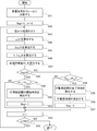
- FIG. 4 is a flowchart showing an example of the operation of the noise detection apparatus 100 according to the present embodiment.
- the frame dividing unit 1111 of the converting unit 111 of the calculating unit 110 divides the acoustic signal into frames having a predetermined time length (step S41).
- the noise detection apparatus 100 sets flag to 0 and n to 0 as initial values (step S42). flag takes a value of 0 or 1.
- n is a variable indicating a frame number, and the upper limit is a number obtained by subtracting 1 from the number divided in step S41 (denoted as DIV).
- the windowing processing unit 1112 of the conversion unit 111 performs windowing processing on the signal samples included in the divided frames (step S43).
- the Fourier transform unit 1113 of the transform unit 111 calculates the phase spectrum pn (k) by performing Fourier transform on the signal sample that has been windowed for each frame (step S44).
- the change amount calculation unit 1121 of the index calculation unit 112 of the calculation unit 110 calculates the change amount ⁇ p n (k) of the phase component (step S45).
- the difference calculation unit 1122 of the index calculation unit 112 calculates a change amount difference ⁇ p n (k) that is a change amount of the change amount of the phase component (step S46).
- the feature amount calculation unit 1123 of the index calculation unit 112 calculates a phase feature amount PL n that is an index indicating the linearity of the phase spectrum p n (k) (step S47).
- step S48 determines whether or not the flag is 0 (step S48). If the flag is not 0 (NO in step S48), the process proceeds to step S54. If flag is 0 (YES in step S48), the process proceeds to step S49. This flag indicates whether or not the start time of the hitting section is detected. When it is 0, it indicates that it is not detected, and when it is 1, it indicates that it is detected.
- step S48 determines whether the phase feature amount PL n calculated in step S47 is smaller than the threshold Th start . It is determined whether or not (step S49).
- phase feature amount PL n is equal to or greater than threshold value Th start (NO in step S49)
- noise detection apparatus 100 increments n (step S52) and determines whether or not incremented n is smaller than DIV (step S52).
- step S53 If n is greater than or equal to DIV (NO in step S53), noise detection apparatus 100 ends the process. If n is smaller than DIV (YES in step S53), noise detection apparatus 100 returns the process to step S43. And the noise detection apparatus 100 performs the process of step S43 to step S48 with respect to the following flame
- the first detection unit 120 detects the frame indicated by the frame number associated with the phase feature amount PL n as the hitting unit section. Is detected as a start frame (start time) (step S50). And the noise detection apparatus 100 sets flag to 1 (step S51). And the noise detection apparatus 100 advances a process to step S52. Then, noise detection apparatus 100 increments n (step S52), and when incremented n is smaller than DIV (YES in step S53), processing from step S43 to step S48 is executed for the next frame.
- step S48 determines whether the phase feature amount PL n calculated in step S47 is greater than the threshold Th end . It is determined whether or not (step S54).
- phase feature amount PL n is equal to or smaller than threshold value Th end (NO in step S54)
- noise detection apparatus 100 advances the process to step S52.
- the second detection unit 130 relates to the phase feature amount PL n and is one frame before the frame indicated by the frame number.
- the frame is detected as the end frame (end time) of the hitting section (step S55).
- the 2nd detection part 130 determines a hit
- the noise detection apparatus 100 may sequentially receive acoustic signals and perform noise detection processing in real time. And the noise detection apparatus 100 may complete
- the first detection unit 120 compares the feature amount calculated by the calculation unit 110 with the first threshold value. Then, the first detection unit 120 calculates the feature amount when the steepness of the change in the acoustic signal represented by the feature amount is larger than the steepness of the change in the acoustic signal represented by the first threshold value. The frame is detected as the start time of the impact sound section. Further, the second detection unit 130 compares the feature amount calculated by the calculation unit 110 with the second threshold value. The second threshold value represents a steepness smaller than the steepness of the change in the acoustic signal represented by the first threshold value.
- the second detection unit 130 When the steepness of the change in the acoustic signal represented by the feature amount is equal to or less than the steepness of the change in the acoustic signal represented by the second threshold, the second detection unit 130 The previous frame is detected as the end time of the impact sound section.
- the noise detection apparatus 100 can detect the time when the steep change of the acoustic signal starts and the time when it ends more accurately.
- the point in time when the abrupt change of the acoustic signal starts corresponds to the start time of the hitting section shown in FIG.
- the time when the steep change of the acoustic signal ends corresponds to the end time of the hitting section. Therefore, the noise detection apparatus 100 can more accurately detect the start time and the end time of the hitting section shown in FIG. 1 among the impact sounds.
- the noise detection apparatus 100 can detect the start time and the end time of the hitting section. Thereby, the noise detection apparatus 100 can determine a hit
- the noise detection apparatus 100 can further improve the recognition performance when performing speech recognition. For example, a scene where a voice is recognized when a store clerk is serving a customer at a store window or the like will be described. In this situation, when the store clerk is the target speaker and the store clerk's voice is the target voice, the store clerk talks while showing the catalog to the customer, or operates the keyboard and mouse to enter customer information. However, there are cases where customers come in and speak. In this case, since the object sound and the work sound generated by the target speaker are superimposed on the target voice, the voice recognition accuracy in the collected acoustic signal may be lowered.
- the noise detection apparatus 100 it is possible to determine a section of impact sound such as work sound, in particular, a hitting section, and thus the apparatus for suppressing noise is determined. It is possible to perform processing for suppressing noise in the section. As a result, it is possible to extract a voice with suppressed noise, and thus it is possible to improve the recognition accuracy for this voice.
- the determination of the hitting section by the noise detection device 100 should be preferably applied to the noise detection field. Can do.
- the present invention can be applied to cases where the user views the collected sound by reducing noise, for example, touching a microphone or a large impact sound by noise suppression.
- the noise detection apparatus 100 can detect an event such as door opening / closing and applause.
- the noise detection apparatus 100 can be applied to, for example, detection of a section that suppresses noise such as a sound generated by a speaker when the target speaker's voice is desired.
- the noise detection apparatus 100 can suppress the superimposed noise from the target signals such as voice and music and the noise signal superimposed on them.
- the noise detection apparatus 100 can be applied to any other signal processing apparatus that is required to determine whether or not an input signal includes a rapidly changing section.
- the feature amount calculation unit 1123 has been described as obtaining the phase feature amount PL n by calculating the average value of the change amount difference ⁇ p n (k) as the feature amount.
- description will be given of the case where the feature quantity calculating unit 1123 obtains the phase feature quantity PL n by calculating the distribution of the change amount difference ⁇ p n (k) as the feature quantity.
- the feature amount calculation unit 1123 uses the change amount difference ⁇ p n (k) received from the difference calculation unit 1122 to obtain a histogram in the frame in which the change amount difference ⁇ p n (k) is calculated. At this time, the feature amount calculation unit 1123 obtains a histogram using the value of the change amount difference ⁇ p n (k) as a bin.
- the feature amount calculation unit 1123 can determine that the linearity of the phase spectrum is high. Then, the feature amount calculation unit 1123 may calculate the index PL n based on this histogram.
- the feature amount calculation unit 1123 determines an arbitrary frequency index range, for example, k-100 to k-1, k to k + 99, etc., and uses the frequency index value as a bin to calculate the change amount difference ⁇ p n (k). A distribution may be obtained. Then, the feature quantity calculation unit 1123 may calculate the inter-distribution distance based on this distribution and calculate the index PL n .
- the feature amount calculation unit 1123 can calculate the feature amount based on the distribution, not the feature amount based on the average value of the change amount difference ⁇ p n (k). And the noise detection apparatus 100 can determine a hit
- FIG. 5 is a functional block diagram showing an example of a functional configuration of the noise suppression apparatus 200 according to the present embodiment.
- members having the same functions as those included in the drawings described in the second embodiment described above are given the same reference numerals, and descriptions thereof are omitted.
- the noise suppression apparatus 200 includes the noise detection apparatus 10 described in the first embodiment or the noise detection apparatus 100 described in the second embodiment, and a replacement unit 210.
- the functional configurations of the noise detection device 10 and the noise detection device 100 are the same as the functional configuration described with reference to FIG. 2 and FIG. In the following description, it is assumed that the noise suppression device 200 includes the noise detection device 100, but it goes without saying that the noise suppression device 200 may be configured to include the noise detection device 10.
- the noise detection apparatus 100 outputs information indicating the hitting section to the replacing unit 210. Specifically, the noise detection apparatus 100 uses the information indicating the start time calculated by the first detection unit 120 and the end time calculated by the second detection unit 130 as information indicating the hitting section. It outputs to the substitution part 210 with the information which shows the acoustic signal used as the object which determines an impact part area.
- the replacement unit 210 receives information indicating the hitting section from the noise detection device 100 together with information indicating the acoustic signal. Then, the replacement unit 210 receives an acoustic signal represented by information indicating the received acoustic signal, for example, from the outside of the noise suppression device 200. Then, the replacement unit 210 associates the time information of the received acoustic signal with the time information represented by the information indicating the hitting section interval received from the noise detection apparatus 100, and the start time of the hitting section in the received acoustic signal. And the end time.
- the replacement unit 210 replaces the signal of the frame included in the hitting section with the signal of the immediately preceding frame using the signal of the frame immediately before the frame indicated by the specified start time.
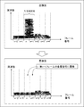
- FIG. 6 is a diagram for explaining the operation of the replacement unit 210.
- the horizontal axis shown in FIG. 6 indicates the frame number, and the vertical axis indicates the frequency (kHz).
- the upper diagram in FIG. 6 shows the acoustic signal before replacement, and the lower diagram in FIG. 6 shows the acoustic signal after replacement.
- the hitting section determined by the noise detection device 100 is a section from the nth frame to the n + 1th frame.
- the start time of the hitting section is the nth frame and the end time is the (n + 1) th frame.
- the replacement unit 210 the n-th frame is the signal samples of the n + 1 frame x n (t) and x n + 1 a (t), the n-1 frame signal samples x n which is the immediately preceding frame start time -1 Replace with (t).
- the signals of the nth frame and the (n + 1) th frame are replaced with the same signals as the signals of the (n ⁇ 1) th frame.
- the replacement unit 210 replaces the signal of the hitting section with the signal of the frame immediately before the start time of the hitting section, but the present embodiment is not limited thereto. Is not to be done.
- the replacement unit 210 may replace the feature amount of the hitting section with the feature amount of the frame immediately before the start time of the hitting section. This feature amount may be, for example, a mel frequency cepstrum coefficient generally used for speech recognition, a mel logarithmic spectrum, or the like, or other feature amount.
- the replacement unit 210 uses information related to a frame different from the frame of the hitting section (for example, a signal of the frame other than the hitting section, a feature amount, etc.) and relates to the frame of the hitting section. The information is replaced with information related to a frame different from the frame of the hitting section.
- the signal that the replacement unit 210 replaces the signal of the striking section may be a signal of a frame immediately before the start time of the striking section, or a signal of a frame immediately after the end time of the striking section. Also good.
- the replacement signal may be a signal of a frame immediately before the start time of the hitting section and a signal of a frame immediately after the end time of the hitting section.
- the replacement unit 210 calculates the center time of the hitting section, replaces the signal of the frame before the calculated center time with the signal of the frame immediately before the start time of the hitting section, and is later than the calculated center time.
- the signal of the frame may be replaced with the signal of the frame immediately after the end time of the hitting section. At this time, the time calculated by the replacement unit 210 may not be the central time, and may be an arbitrary time.
- the replacement unit 210 calculates the signal of the striking section using the signal of the frame immediately before the start time of the striking section and the signal of the frame immediately after the end time of the striking section, and the striking section May be interpolated with the calculated signal. For example, the replacement unit 210 adds an arbitrary weight to the signal of the frame immediately before the start time of the hitting section and the signal of the frame immediately after the end time of the hitting section, thereby adding the signal of the hitting section. And the striking section may be interpolated with the calculated signal.
- the replacement unit 210 may replace the signal of the hitting section with a noise such as a zero signal or white noise.
- the replacement unit 210 may delete the signal of the hitting section and generate a signal that connects the frame immediately before the start time of the hitting section and the frame immediately after the end time of the hitting section.
- the replacement unit 210 may detect a predetermined number of frames from the frame immediately after the end time of the hitting section as the impact sound attenuation section and perform further noise suppression processing.
- FIG. 7 is a flowchart showing an example of the operation of the noise suppression apparatus 200 according to the present embodiment.
- step S71 the noise detection device 100 of the noise suppression device 200 performs a striking section determination process for determining a striking section.
- This step S71 indicates that the processes of steps S41 to S56 described with reference to FIG. 4 are performed.
- the replacement unit 210 identifies the frame immediately before the start time of the hitting section determined in step S71 (step S72). Then, the replacement unit 210 replaces the signal of the frame corresponding to the hitting section section of the acoustic signal with the signal of the identified frame (step S73). Thereby, the replacement unit 210 can suppress noise in the hitting section of the acoustic signal. Thus, the noise suppression device 200 ends the process.
- the noise in the striking section is suppressed by replacing the signal in the striking section with a signal of a frame different from the frame in the striking section. can do.
- the length of the striking section when the replacement section 210 performs the replacement is preferable as the length of the striking section when the replacement section 210 performs the replacement. This is because, when speech recognition of an acoustic signal subjected to noise suppression processing is performed, the speech recognition rate can be improved when the replacement interval is shorter.
- the noise suppression apparatus 200 can obtain an effect that noise can be further suppressed in addition to the effect according to the second embodiment described above.
- the replacement unit 210 included in the noise suppression device 200 has been described as an example of a configuration different from that of the noise detection device 100.
- the present embodiment is not limited to this. It is not something.
- the replacement unit 210 may be built in the noise detection apparatus 100.
- the noise detection apparatus 100 includes a calculation unit 110, a first detection unit 120, a second detection unit 130, a storage unit 140, and a replacement unit 210.
- Such a noise detection apparatus 100 can obtain the same effect as the noise suppression apparatus 200 according to the present embodiment.
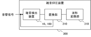
- FIG. 8 is a functional block diagram illustrating an example of a functional configuration of the noise suppression apparatus 300 according to the present embodiment.
- members having the same functions as those included in the drawings described in the second and third embodiments described above are denoted by the same reference numerals and description thereof is omitted.
- the noise suppression apparatus 300 includes the noise detection apparatus 10 described in the first embodiment or the noise detection apparatus 100 described in the second embodiment, a replacement unit 210, and a waveform conversion unit 310. And.
- the functional configurations of the noise detection device 10 and the noise detection device 100 are the same as the functional configuration described with reference to FIG. 2 and FIG. In the following description, it is assumed that the noise suppression device 200 includes the noise detection device 100, but it goes without saying that the noise suppression device 200 may be configured to include the noise detection device 10.
- the waveform conversion unit 310 receives from the replacement unit 210 the signal on which the replacement unit 210 has performed suppression processing. Specifically, the waveform converter 310 receives the signal after the replacement unit 210 replaces the signal of the frame corresponding to the hitting section section of the acoustic signal with the signal of the identified frame.
- the specified frame is, for example, a frame immediately before the start time of the hitting section in the acoustic signal.
- the waveform converter 310 converts the received signal into a form usable by the user. Specifically, the waveform converter 310 converts the received signal into a waveform that can be viewed and heard by the user.
- the waveform converting unit 310 performs inverse Fourier transform on the received signal, thereby converting the received signal into a waveform. Convert to
- the waveform converter 310 can display the waveform on a display device (not shown).
- the noise suppression apparatus 300 can present to the user an acoustic signal in a state where the user can use it, and the noise is suppressed.
- the waveform conversion unit 310 included in the noise suppression device 300 has been described as an example of a configuration different from that of the noise detection device 100.
- the present embodiment is not limited to this. Is not to be done.
- the waveform conversion unit 310 may be built in the noise detection apparatus 100. Such a noise detection apparatus 100 can obtain the same effect as the noise suppression apparatus 300 according to the present embodiment.
- noise suppression processing In order to improve the speech signal recognition rate, it is necessary to appropriately perform processing (noise suppression processing) for reducing noise from the speech signal. This is because if the noise suppression process is insufficient, noise remains superimposed on the audio signal, and the recognition rate of the audio signal is reduced. Moreover, if the noise suppression process is excessively performed, even necessary speech is suppressed as noise, and the recognition rate of the speech signal is reduced.
- an object of the present embodiment is to more effectively perform noise suppression processing of an audio signal.
- FIG. 9 is a functional block diagram illustrating an example of a functional configuration of the noise suppression device 400 according to the present embodiment.
- noise suppression apparatus 400 according to the present embodiment includes detection section 410 and replacement section 420.
- the detection unit 410 detects the first section of the impact sound from the acoustic signal including the impact sound.
- This first section is a section where the power is larger than the subsequent section following the first section and the power exists in a wide band.
- the first section detected by the detection unit 410 is the hitting section described with reference to FIG.
- the detection unit 410 is realized by, for example, the noise detection apparatus 100 in each of the above-described embodiments.
- the noise detection apparatus 100 may detect the hitting section using an index (phase feature amount PL n ) indicating the linearity of the phase spectrum.
- the detection unit 410 is not limited to that realized by the noise detection device in each of the above-described embodiments.
- a sudden change in volume, a change in magnitude of an amplitude feature, a power spectrum feature, a time change thereof, The flatness of the spectrum may be calculated as a feature amount, and the hitting section may be detected using the calculated feature amount.
- the detection part 410 may detect a hit
- damage part area is not specifically limited.
- the detection unit 410 outputs the detected information indicating the hitting section to the replacement unit 420.
- the replacement unit 420 acquires section information indicating the hitting section from the detection unit 410. Then, the replacement unit 420 specifies a hitting unit section indicated by the received section information in the acoustic signal. Then, a frame different from the frame included in the specified section is specified as a frame for replacing information.
- the frame that the replacement unit 420 specifies as a frame for replacing information may be, for example, the frame immediately before the start time of the hitting unit section, similarly to the replacement unit 210 in the third embodiment described above. Further, the frame specified by the replacement unit 420 as a frame for replacing information may be, for example, a frame immediately after the end time of the hitting section.
- the replacement unit 420 replaces the second information related to the frame included in the hitting section with the first information using the specified first information related to the frame for replacing the information.
- the information related to the frame is, for example, an acoustic signal (signal sample) included in the frame
- the replacement unit 420 replaces the signal sample of the frame included in the striking unit section with the signal sample of the specified frame.
- the replacement unit 420 uses the first information related to the specified frame to replace information to identify the frame included in the hitting unit section. Interpolation may be performed using information based on the information of 1.
- the replacement unit 420 may replace the signal of the hitting section with a noise such as a zero signal or white noise.
- the replacement unit 420 may delete the signal of the hitting section and generate a signal connecting the frame immediately before the start time of the hitting section and the frame immediately after the end time of the hitting section.
- FIG. 10 is a flowchart showing an example of the operation of the noise suppression apparatus 400 according to the present embodiment.
- step S101 the detection unit 410 detects a hitting section (step S101).
- the process of step S101 may be the same process as step S71 of FIG.
- the replacement unit 420 specifies a frame for replacing information with the frame in the section detected in step S101 (step S102). Then, the replacement unit 420 replaces the second information related to the frame corresponding to the detected section of the acoustic signal with the first information related to the identified frame (step S103). Thereby, the replacement part 420 can suppress the noise of the impact part hit
- the second information related to the frame of the impact sound hitting section is stored in a frame different from the frame of the impact sound hitting section. It can be replaced with related first information. Thereby, the noise suppression apparatus 400 can suppress the noise in the impact sound hitting section.
- the noise suppression device 400 can obtain an effect that the noise suppression processing of the voice signal can be performed more effectively.
- FIG. 11 Each part of the noise detection device (10, 100) shown in FIGS. 2 and 3 and the noise suppression device (200, 300, 400) shown in FIGS. 5, 8, and 9 is the same as the hardware shown in FIG. It may be realized with hardware resources. That is, the configuration shown in FIG. 11 includes a RAM (Random Access Memory) 91, a ROM (Read Only Memory) 92, a communication interface 93, a storage medium 94, and a CPU (Central Processing Unit) 95. The CPU 95 reads out various software programs (computer programs) stored in the ROM 92 or the storage medium 94 to the RAM 91 and executes them, so that the noise detection devices (10, 100) and the noise suppression devices (200, 300, 400) are executed. It governs overall operation.
- RAM Random Access Memory
- ROM Read Only Memory
- the CPU 95 reads out various software programs (computer programs) stored in the ROM 92 or the storage medium 94 to the RAM 91 and executes them, so that the noise detection devices (10, 100) and the noise suppression
- the CPU 95 executes each function (each unit) included in the noise detection device (10, 100) and the noise suppression device (200, 300, 400) while referring to the ROM 92 or the storage medium 94 as appropriate. Execute the software program to be executed.
- the present invention described by taking each embodiment as an example supplied a computer program capable of realizing the functions described above to the noise detection devices (10, 100) and the noise suppression devices (200, 300, 400). Thereafter, the computer program is read out by the CPU 95 to the RAM 91 and executed.
- the supplied computer program may be stored in a computer-readable storage device such as a readable / writable memory (temporary storage medium) or a hard disk device.
- a computer-readable storage device such as a readable / writable memory (temporary storage medium) or a hard disk device.
- the present invention can be understood as being configured by a code representing the computer program or a storage medium storing the computer program.
- the noise detection device (10, 100) shown in FIGS. 2 and 3 and the noise suppression device (200, 300, 400) shown in FIGS. 5, 8, and 9 are shown in each block.
- the case where the function is realized by a software program has been described as an example executed by the CPU 95 shown in FIG.
- some or all of the functions shown in the blocks shown in FIGS. 2, 3, 5, 8, and 9 may be realized as hardware circuits.
- the calculation means which calculates the feature-value showing the steepness of the change of the said acoustic signal from the acoustic signal containing an impact sound for every flame
- the first detection unit compares the feature quantity with a first threshold value, and the steepness of the change in the acoustic signal represented by the feature quantity is represented by the first threshold value.
- a frame in which the feature value is calculated is detected as a start time of the impact sound section, and the second detection unit is configured to detect the feature value and the first sound value.
- the second threshold value representing a steepness smaller than the steepness of the change of the acoustic signal represented by the threshold value is compared, and the steepness of the change of the acoustic signal represented by the feature amount is the second threshold value.
- the supplementary note 1 wherein a frame immediately before the frame for which the feature amount is calculated is detected as an end time of the impact sound section when the acoustic signal is represented by Noise detection device.
- the said calculation means is provided with the conversion means which converts the said acoustic signal into a phase spectrum, and the linearity calculation means which calculates the linearity of the said phase spectrum, The said linearity calculation means calculated, The noise detection apparatus according to appendix 1 or 2, wherein an index representing linearity of a phase spectrum is calculated as the feature amount.
- the said linearity calculation means calculates the linearity of the said phase spectrum using the value based on the dispersion
- the noise detection device according to supplementary note 3, wherein the noise detection device is calculated.
- the second information related to the frame included in the shock sound section is replaced with the first information.
- noise detection according to any one of appendices 1 to 4, further comprising replacement means for interpolating a frame included in the impact sound section with information based on the first information. apparatus.
- a noise suppression device comprising: replacement means for replacing with information or interpolating a frame included in the first section with information based on the first information.
- a noise suppression apparatus comprising: a detection unit that detects the signal and a replacement unit that replaces or deletes the signal in the first section with a predetermined signal prepared in advance.
- the said detection means calculates the feature-value showing the steepness of the change of the said acoustic signal from the said acoustic signal for every flame
- the said characteristic First detection means for detecting a frame having a greater signal change steepness than the audio signal based on the amount as the start time of the first section, and continuing from the start time based on the feature amount Or a second detection means for detecting the last frame of the frames whose signal change is sharper than the audio signal as the end time of the first section.
- the noise suppression device according to 7.
- the first detection unit compares the feature quantity with a first threshold value, and the steepness of the change in the acoustic signal represented by the feature quantity is represented by the first threshold value.
- a frame in which the feature amount is calculated is detected as a start time of the first section, and the second detection unit is configured to detect the feature amount and the first
- the second threshold value representing a steepness smaller than the steepness of the change of the acoustic signal represented by the threshold value is compared, and the steepness of the change of the acoustic signal represented by the feature amount is the second threshold value.
- the said calculation means is provided with the conversion means which converts the said acoustic signal into a phase spectrum, and the linearity calculation means which calculates the linearity of the said phase spectrum, The said linearity calculation means calculated, The noise suppression device according to appendix 8 or 9, wherein an index representing linearity of a phase spectrum is calculated as the feature amount.
- the said linearity calculation means calculates
- a feature amount representing the steepness of the change of the acoustic signal is calculated for each frame obtained by dividing the acoustic signal into a predetermined time length, and based on the feature amount, A frame in which the change of the signal is sharper than that of the audio signal is detected as a start time of the impact sound section where the impact sound exists, and based on the feature amount, the frame is continuously detected from the start time.
- a noise detection method comprising: detecting a last frame of frames having a large signal change steepness as an end time of the impact sound section.
- the first section of the impact sound From the acoustic signal containing the impact sound, it is the first section of the impact sound, the power is larger than the subsequent section following the first section, and the first section where the power exists in a wide band And the second information related to the frame included in the first section is replaced with the first information using the first information related to the frame different from the frame included in the first section. Or interpolating a frame included in the first section with information based on the first information.
- Noise detection apparatus 11
- Calculation part 12 1st detection part 13 2nd detection part 100
- Noise detection apparatus 110 Calculation part 111 Conversion part 1111 Frame division part 1112 Windowing process part 1113 Fourier transform part 112
- Index calculation part 1121 Change amount calculation Unit 1122 difference calculation unit 1123 feature quantity calculation unit 120 first detection unit 130 second detection unit 140 storage unit 200 noise suppression device 210 replacement unit 300 noise suppression device 310 waveform conversion unit 400 noise suppression device 410 detection unit 420 replacement unit
Landscapes
- Engineering & Computer Science (AREA)
- Computational Linguistics (AREA)
- Quality & Reliability (AREA)
- Signal Processing (AREA)
- Health & Medical Sciences (AREA)
- Audiology, Speech & Language Pathology (AREA)
- Human Computer Interaction (AREA)
- Physics & Mathematics (AREA)
- Acoustics & Sound (AREA)
- Multimedia (AREA)
- Measurement Of Mechanical Vibrations Or Ultrasonic Waves (AREA)
Abstract
L'invention concerne une technique permettant de détecter judicieusement un intervalle contenant un bruit d'impact à partir d'un signal acoustique. Un dispositif de détection de bruit comprend : une unité de calcul conçue pour calculer, à partir du signal acoustique contenant le bruit d'impact, une quantité caractéristique représentant un gradient dans un signal acoustique pour chaque trame ayant une longueur de temps prescrite et en laquelle le signal acoustique est divisé ; une première unité de détection conçue pour détecter, sur la base de la quantité caractéristique, une trame ayant un gradient de signal supérieur à celui d'un signal de parole au titre de l'instant de début d'un intervalle de bruit d'impact au cours duquel le bruit d'impact existe ; et une seconde unité de détection conçue pour détecter, sur la base de la quantité caractéristique, la dernière trame ayant continuellement un gradient de signal supérieur à celui d'un signal de parole à partir de l'instant de début au titre de la fin de l'intervalle de bruit d'impact.
Priority Applications (1)
| Application Number | Priority Date | Filing Date | Title |
|---|---|---|---|
| JP2017524606A JPWO2016203753A1 (ja) | 2015-06-16 | 2016-06-13 | 雑音検出装置、雑音抑圧装置、雑音検出方法、雑音抑圧方法、および、プログラム |
Applications Claiming Priority (2)
| Application Number | Priority Date | Filing Date | Title |
|---|---|---|---|
| JP2015121229 | 2015-06-16 | ||
| JP2015-121229 | 2015-06-16 |
Publications (1)
| Publication Number | Publication Date |
|---|---|
| WO2016203753A1 true WO2016203753A1 (fr) | 2016-12-22 |
Family
ID=57545516
Family Applications (1)
| Application Number | Title | Priority Date | Filing Date |
|---|---|---|---|
| PCT/JP2016/002839 Ceased WO2016203753A1 (fr) | 2015-06-16 | 2016-06-13 | Dispositif et procédé de détection de bruit, dispositif et procédé de suppression de bruit et support d'enregistrement |
Country Status (2)
| Country | Link |
|---|---|
| JP (1) | JPWO2016203753A1 (fr) |
| WO (1) | WO2016203753A1 (fr) |
Cited By (1)
| Publication number | Priority date | Publication date | Assignee | Title |
|---|---|---|---|---|
| WO2020039598A1 (fr) * | 2018-08-24 | 2020-02-27 | 日本電気株式会社 | Dispositif de traitement de signal, procédé de traitement de signal et programme de traitement de signal |
Citations (7)
| Publication number | Priority date | Publication date | Assignee | Title |
|---|---|---|---|---|
| JPH06130984A (ja) * | 1992-10-21 | 1994-05-13 | Sanyo Electric Co Ltd | 音声認識装置 |
| JP2001236085A (ja) * | 2000-02-25 | 2001-08-31 | Matsushita Electric Ind Co Ltd | 音声区間検出装置、定常雑音区間検出装置、非定常雑音区間検出装置、及び雑音区間検出装置 |
| JP2008102551A (ja) * | 2007-12-27 | 2008-05-01 | Sony Corp | 音声信号の処理装置およびその処理方法 |
| JP2011100082A (ja) * | 2009-11-09 | 2011-05-19 | Nec Corp | 信号処理方法、情報処理装置、及び信号処理プログラム |
| JP2012027186A (ja) * | 2010-07-22 | 2012-02-09 | Sony Corp | 音声信号処理装置、音声信号処理方法及びプログラム |
| JP2012127701A (ja) * | 2010-12-13 | 2012-07-05 | Sogo Keibi Hosho Co Ltd | 音検出装置および音検出方法 |
| WO2015029546A1 (fr) * | 2013-08-30 | 2015-03-05 | 日本電気株式会社 | Dispositif de traitement de signal, procédé de traitement de signal et programme de traitement de signal |
-
2016
- 2016-06-13 JP JP2017524606A patent/JPWO2016203753A1/ja active Pending
- 2016-06-13 WO PCT/JP2016/002839 patent/WO2016203753A1/fr not_active Ceased
Patent Citations (7)
| Publication number | Priority date | Publication date | Assignee | Title |
|---|---|---|---|---|
| JPH06130984A (ja) * | 1992-10-21 | 1994-05-13 | Sanyo Electric Co Ltd | 音声認識装置 |
| JP2001236085A (ja) * | 2000-02-25 | 2001-08-31 | Matsushita Electric Ind Co Ltd | 音声区間検出装置、定常雑音区間検出装置、非定常雑音区間検出装置、及び雑音区間検出装置 |
| JP2008102551A (ja) * | 2007-12-27 | 2008-05-01 | Sony Corp | 音声信号の処理装置およびその処理方法 |
| JP2011100082A (ja) * | 2009-11-09 | 2011-05-19 | Nec Corp | 信号処理方法、情報処理装置、及び信号処理プログラム |
| JP2012027186A (ja) * | 2010-07-22 | 2012-02-09 | Sony Corp | 音声信号処理装置、音声信号処理方法及びプログラム |
| JP2012127701A (ja) * | 2010-12-13 | 2012-07-05 | Sogo Keibi Hosho Co Ltd | 音検出装置および音検出方法 |
| WO2015029546A1 (fr) * | 2013-08-30 | 2015-03-05 | 日本電気株式会社 | Dispositif de traitement de signal, procédé de traitement de signal et programme de traitement de signal |
Cited By (4)
| Publication number | Priority date | Publication date | Assignee | Title |
|---|---|---|---|---|
| WO2020039598A1 (fr) * | 2018-08-24 | 2020-02-27 | 日本電気株式会社 | Dispositif de traitement de signal, procédé de traitement de signal et programme de traitement de signal |
| JPWO2020039598A1 (ja) * | 2018-08-24 | 2021-08-12 | 日本電気株式会社 | 信号処理装置、信号処理方法および信号処理プログラム |
| JP7152112B2 (ja) | 2018-08-24 | 2022-10-12 | 日本電気株式会社 | 信号処理装置、信号処理方法および信号処理プログラム |
| US11769517B2 (en) | 2018-08-24 | 2023-09-26 | Nec Corporation | Signal processing apparatus, signal processing method, and signal processing program |
Also Published As
| Publication number | Publication date |
|---|---|
| JPWO2016203753A1 (ja) | 2018-04-19 |
Similar Documents
| Publication | Publication Date | Title |
|---|---|---|
| JP5127754B2 (ja) | 信号処理装置 | |
| EP3190702B1 (fr) | Organe de commande de niveleur de volume et procédé de commande | |
| US8775173B2 (en) | Erroneous detection determination device, erroneous detection determination method, and storage medium storing erroneous detection determination program | |
| JP4818335B2 (ja) | 信号帯域拡張装置 | |
| KR101616112B1 (ko) | 음성 특징 벡터를 이용한 화자 분리 시스템 및 방법 | |
| US20140177853A1 (en) | Sound processing device, sound processing method, and program | |
| CN101149928A (zh) | 声音信号处理方法、声音信号处理设备及计算机程序 | |
| JP2016180839A (ja) | 雑音抑圧音声認識装置およびそのプログラム | |
| CN113316075B (zh) | 一种啸叫检测方法、装置及电子设备 | |
| JP5443547B2 (ja) | 信号処理装置 | |
| JP2017187676A (ja) | 音声判別装置、音声判別方法、コンピュータプログラム | |
| WO2012105386A1 (fr) | Dispositif de détection de segments sonores, procédé de détection de segments sonores et programme de détection de segments sonores | |
| WO2016203753A1 (fr) | Dispositif et procédé de détection de bruit, dispositif et procédé de suppression de bruit et support d'enregistrement | |
| US9697848B2 (en) | Noise suppression device and method of noise suppression | |
| JP4445460B2 (ja) | 音声処理装置及び音声処理方法 | |
| JP6599408B2 (ja) | 音響信号処理装置、方法及びプログラム | |
| JP2017009657A (ja) | 音声強調装置、および音声強調方法 | |
| JP2020190606A (ja) | 音声雑音除去装置及びプログラム | |
| JP2014186295A (ja) | 音声区間検出装置、音声認識装置、その方法、及びプログラム | |
| JP2006126859A5 (fr) | ||
| JP6559576B2 (ja) | 雑音抑圧装置、雑音抑圧方法及びプログラム | |
| JP6930089B2 (ja) | 音響処理方法および音響処理装置 | |
| JP5272141B2 (ja) | 音声処理装置およびプログラム | |
| CN114495961B (zh) | 语音降噪方法、装置、电子设备以及计算机可读存储介质 | |
| US11348596B2 (en) | Voice processing method for processing voice signal representing voice, voice processing device for processing voice signal representing voice, and recording medium storing program for processing voice signal representing voice |
Legal Events
| Date | Code | Title | Description |
|---|---|---|---|
| 121 | Ep: the epo has been informed by wipo that ep was designated in this application |
Ref document number: 16811228 Country of ref document: EP Kind code of ref document: A1 |
|
| ENP | Entry into the national phase |
Ref document number: 2017524606 Country of ref document: JP Kind code of ref document: A |
|
| NENP | Non-entry into the national phase |
Ref country code: DE |
|
| 122 | Ep: pct application non-entry in european phase |
Ref document number: 16811228 Country of ref document: EP Kind code of ref document: A1 |