WO2016203833A1 - Système - Google Patents
Système Download PDFInfo
- Publication number
- WO2016203833A1 WO2016203833A1 PCT/JP2016/062317 JP2016062317W WO2016203833A1 WO 2016203833 A1 WO2016203833 A1 WO 2016203833A1 JP 2016062317 W JP2016062317 W JP 2016062317W WO 2016203833 A1 WO2016203833 A1 WO 2016203833A1
- Authority
- WO
- WIPO (PCT)
- Prior art keywords
- audio data
- broadcast receiving
- broadcast
- audio
- unit
- Prior art date
- Legal status (The legal status is an assumption and is not a legal conclusion. Google has not performed a legal analysis and makes no representation as to the accuracy of the status listed.)
- Ceased
Links
Images


Classifications
-
- H—ELECTRICITY
- H04—ELECTRIC COMMUNICATION TECHNIQUE
- H04N—PICTORIAL COMMUNICATION, e.g. TELEVISION
- H04N5/00—Details of television systems
-
- H—ELECTRICITY
- H04—ELECTRIC COMMUNICATION TECHNIQUE
- H04N—PICTORIAL COMMUNICATION, e.g. TELEVISION
- H04N21/00—Selective content distribution, e.g. interactive television or video on demand [VOD]
- H04N21/40—Client devices specifically adapted for the reception of or interaction with content, e.g. set-top-box [STB]; Operations thereof
- H04N21/43—Processing of content or additional data, e.g. demultiplexing additional data from a digital video stream; Elementary client operations, e.g. monitoring of home network or synchronising decoder's clock; Client middleware
- H04N21/439—Processing of audio elementary streams
Definitions
- the present invention relates to a system including a broadcast receiving apparatus and a remote controller.
- One of the extended functions of the digital broadcasting service is data broadcasting that transmits digital data using broadcast waves and displays various information such as weather forecasts, news, and recommended programs.
- Many television receivers capable of receiving data broadcasts are already on the market, and many techniques related to data broadcast reception have been disclosed, including Patent Document 1 below.
- TV receivers are also required to expand various functions.
- requests for distribution of content and cooperative applications using a broadband network environment such as the Internet and requests for high resolution / high definition of video content.
- An object of the present invention is to provide a broadcast receiving apparatus that can execute a function with higher added value.
- the system includes a broadcast receiving apparatus capable of receiving digital content including a plurality of audio data transmitted as different audio channels and control information, and a remote controller for controlling the broadcast receiving apparatus.
- the broadcast receiving apparatus includes a receiving unit that receives the digital content and control information, an operation input unit that can input an instruction from the remote controller, and a speaker that can output audio based on the received audio data.
- control unit capable of controlling audio output via the speaker based on an instruction input to the operation input unit, wherein the remote controller outputs the audio data received by the broadcast receiving device
- a volume operation input unit that is a key or button capable of inputting an instruction for volume adjustment processing;
- the control unit changes a combination of audio data to be subjected to the volume adjustment control from among a plurality of audio data received by the receiving unit according to the content of the control information received by the receiving unit, Is used.
- FIG. 1 is a system configuration diagram illustrating an example of a broadcast communication system including a broadcast receiving apparatus according to Embodiment 1.
- FIG. It is explanatory drawing of the outline
- FIG. 1 is a block diagram of a broadcast receiving apparatus according to Embodiment 1.
- FIG. 1 is a block diagram of the logical plane structure of the presentation function of the broadcast receiver which concerns on Example 1.
- FIG. 1 is a system configuration diagram of clock synchronization / presentation synchronization of a broadcast receiving apparatus according to Embodiment 1.
- FIG. 1 is a system configuration diagram of clock synchronization / presentation synchronization of a broadcast receiving apparatus according to Embodiment 1.
- FIG. 1 is a software configuration diagram of a broadcast receiving apparatus according to Embodiment 1.
- FIG. 1 is a block diagram of a broadcast station server according to Embodiment 1.
- FIG. 1 is a block diagram of a service provider server according to Embodiment 1.
- FIG. 1 is a block diagram of a portable information terminal according to Embodiment 1.
- FIG. 1 is a software configuration diagram of a portable information terminal according to Embodiment 1.
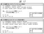
- FIG. It is a figure which shows the data structure of MH-TOT of a broadcast system. It is a figure which shows the format of the JST_time parameter of a broadcast system. It is a figure which shows the calculation method of the present date from MJD of the broadcast receiver which concerns on Example 1.
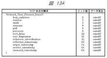
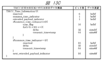
- FIG. 1 It is a figure which shows the structure of the NTP format of a broadcast system. It is a figure which shows the data structure of the MPU time stamp descriptor of a broadcast system. It is a figure which shows the data structure of the time information of the TMCC extension information area
- FIG. It is a figure which shows the data structure of TLV-NIT of a broadcasting system. It is a figure which shows the data structure of the satellite distribution system descriptor of a broadcast system. It is a figure which shows the data structure of the service list descriptor of a broadcast system. It is a figure which shows the data structure of AMT of a broadcast system.
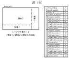
- FIG 3 is an operation sequence diagram at the time of channel selection of the broadcast receiving apparatus according to the first embodiment. It is a figure which shows the data structure of MPT of a broadcast system. It is a figure which shows the data structure of LCT of a broadcast system. It is a figure which shows the example of allocation of the layout to the layout number based on LCT. It is a figure which shows the example of allocation of the layout to the layout number based on LCT. It is a figure which shows the example of allocation of the layout to the layout number based on LCT. It is a figure which shows the example of allocation of the layout to the layout number based on LCT. It is a figure explaining the operation
- FIG. 6 is a block diagram of a broadcast receiving apparatus according to Embodiment 2.
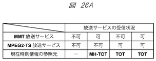
- FIG. 6 is a figure explaining inconsistency of the present time display at the time of broadcast service switching.
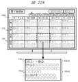
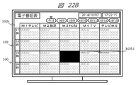
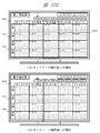
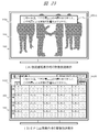
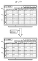
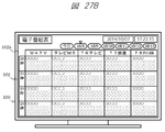
- FIG. 9 is an operation sequence diagram of current time information update processing according to the second embodiment. It is a screen display figure of the EPG screen of the broadcast receiving apparatus which concerns on Example 2. FIG. It is a screen display figure of the EPG screen of the broadcast receiving apparatus which concerns on Example 2. FIG. It is a figure which shows the bit stream structure of the LATM / LOAS format of a broadcasting system. It is a figure which shows an example of a structure of dialog control information. It is a figure which shows the speaker arrangement
- FIG. 1 It is a figure which shows the recommended range of the speaker arrangement
- FIG. It is a figure explaining the encoding system of 22.2ch audio
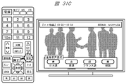
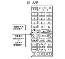
- FIG. It is a conceptual diagram of the dialog control function of a broadcast system. It is a conceptual diagram of the dialog control function of a broadcast system. It is a figure explaining the selection method of the audio
- FIG. It is a figure explaining the selection method of the audio
- FIG. It is a figure explaining the selection method of the audio
- FIG. It is a figure explaining the selection method of the audio
- FIG. It is a figure explaining the selection method of the audio
- FIG. It is a figure explaining the selection method of the audio
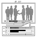
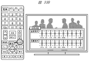
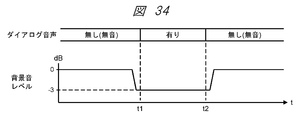
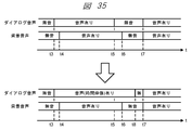
- FIG. It is a figure explaining the volume adjustment method of the dialog sound based on Example 3, and a background sound. It is a figure explaining the volume adjustment method of the dialog sound based on Example 3, and a background sound. It is a figure explaining the volume adjustment method of the dialog sound based on Example 3, and a background sound. It is a screen display figure of the volume level information of the dialog sound based on Example 3, and a background sound. It is a figure explaining the sound quality adjustment method of the dialog sound based on Example 3, and a background sound.
- FIG. 1 is a system configuration diagram illustrating an example of a broadcast communication system including a broadcast receiving apparatus according to the present embodiment.
- the broadcast communication system of the present embodiment includes a broadcast receiving device 100 and an antenna 100a, a broadband network such as the Internet 200, a router device 200r and an access point 200a, a broadcasting station radio tower 300t and a broadcasting satellite (or communication satellite) 300s, a broadcasting station.
- the broadcast receiving apparatus 100 receives the broadcast wave transmitted from the radio tower 300t via the broadcast satellite (or communication satellite) 300s and the antenna 100a. Alternatively, the broadcast wave transmitted from the radio tower 300t may be received directly from the antenna 100a without passing through the broadcast satellite (or communication satellite) 300s.
- the broadcast receiving apparatus 100 can be connected to the Internet 200 via the router apparatus 200r, and can transmit and receive data by communication with each server apparatus and other communication devices on the Internet 200.
- the router device 200r is connected to the Internet 200 by wired communication, is connected to the broadcast receiving device 100 by wired communication or wireless communication, and is connected to the portable information terminal 700 by wireless communication.
- a method such as Wi-Fi (registered trademark) may be used.
- Wi-Fi registered trademark
- each server device and other communication devices on the Internet 200, the broadcast receiving device 100, and the portable information terminal 700 can mutually transmit and receive data via the router device 200r.
- the communication between the broadcast receiving device 100 and the portable information terminal 700 may be performed directly using a method such as BlueTooth (registered trademark) or NFC (Near Field Communication) without using the router device 200r.
- the radio tower 300t is a broadcasting facility of a broadcasting station, and transmits broadcast waves including encoded data of broadcast programs, caption information, other applications, general-purpose data, and the like.
- the broadcast satellite (or communication satellite) 300s receives the broadcast wave transmitted from the radio tower 300t of the broadcast station, performs appropriate frequency conversion, and the like, and then broadcasts the antenna 100a connected to the broadcast receiving device 100 to the antenna 100a. It is a repeater that retransmits waves.
- the broadcasting station includes a broadcasting station server 300.
- the broadcast station server 300 stores metadata such as broadcast programs (video content, etc.) and program titles, program IDs, program outlines, performer information, broadcast date and time of each broadcast program, and the video content and each metadata. Based on the contract, it can be provided to the service provider.
- the provision of the moving image content and each metadata to the service provider may be performed through an API (Application Programming Interface) included in the broadcast station server 300.
- API Application Programming Interface
- Service provider server 400 is a server device prepared by a service provider, and is capable of providing various services linked to broadcast programs distributed from broadcast stations.
- the service provider server 400 also stores, manages, and distributes video content and metadata provided from the broadcast station server 300, various contents and applications linked to broadcast programs, and the like.
- it in response to an inquiry from a television receiver or the like, it also has a function of searching for available contents and applications and providing a list.
- the storage, management and distribution of the content and metadata and the storage, management and distribution of the application may be performed by different server devices.
- the broadcasting station and the service provider may be the same or different.
- a plurality of service provider servers 400 may be prepared for different services.
- the function of the service provider server 400 may be provided by the broadcast station server 300.
- the other application server 500 is a known server device that stores, manages, and distributes other general applications, operation programs, contents, data, and the like. There may be a plurality of other application servers 500 on the Internet 200.
- the mobile telephone communication server 600 is connected to the Internet 200, and is connected to the portable information terminal 700 via the base station 600b.
- the mobile telephone communication server 600 manages telephone communication (call) and data transmission / reception via the mobile telephone communication network of the portable information terminal 700, and each server device and other communication devices on the portable information terminal 700 and the Internet 200. Data can be sent and received through communication with the.
- the communication between the base station 600b and the portable information terminal 700 is W-CDMA (Wideband Code Division Multiple Access) (registered trademark) method, GSM (Global System for Mobile communications) (registered trademark) method, LTE (LongTerm Term) method. Alternatively, it may be performed by other communication methods.
- the portable information terminal 700 has a function of telephone communication (call) and data transmission / reception via a mobile telephone communication network and a function of wireless communication by Wi-Fi (registered trademark) or the like.
- the portable information terminal 700 can be connected to the Internet 200 via the router device 200r and the access point 200a, or via the mobile phone communication network base station 600b and the mobile phone communication server 600. It is possible to send and receive data by communication with each server device and other communication devices.
- the access point 200a is connected to the Internet 200 by wired communication, and is connected to the portable information terminal 700 by wireless communication. For the wireless communication, a method such as Wi-Fi (registered trademark) may be used. Communication between portable information terminal 700 and broadcast receiving apparatus 100 is performed via access point 200a and Internet 200 and router apparatus 200r, or through base station 600b and mobile telephone communication server 600, Internet 200 and router apparatus 200r. It may be carried out via.
- the broadcast receiving apparatus 100 shown in FIG. 1 is defined by the MPEG (Moving Picture Experts Group) -2 system, which is widely adopted in conventional digital broadcasting systems, as a media transport system for transmitting data such as video and audio. It is assumed that the television receiver is compatible with MMT (MPEG Media Transport) instead of TS (Transport Stream) (hereinafter referred to as MPEG2-TS). It may be a television receiver that can support both MPEG2-TS and MMT.
- MPEG2TS Transmission Stream
- MPEG2-TS is characterized in that components such as video and audio constituting a program are multiplexed into one stream together with a control signal and a clock. Since it is handled as one stream including a clock, it is suitable for transmitting one content through one transmission path in which transmission quality is ensured, and has been adopted in many conventional digital broadcasting systems.
- the function of MPEG2-TS in response to environmental changes related to content distribution such as recent diversification of content, diversification of devices that use content, diversification of transmission paths for content distribution, diversification of content storage environment, etc. Therefore, MMT is a newly developed media transport system.
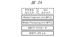
- FIG. 2A shows an example of an outline of the encoded signal in the MMT of the present embodiment.
- the MMT of this embodiment has an MFU (Media Fragment Unit), an MPU (Media Processing Unit), an MMTP (MMT Protocol) payload, and an MMTP packet as elements constituting the encoded signal.
- the MFU is a format at the time of transmission of video or audio, and may be configured in units of NAL (Network Abstraction Layer) units or access units.
- the MPU may be composed of MPU metadata including information on the configuration of the entire MPU, movie fragment metadata including information of encoded media data, and sample data that is encoded media data. Further, it is assumed that MFU can be extracted from the sample data. In the case of media such as video components and audio components, the presentation time and decoding time may be specified in units of MPUs or access units.
- FIG. 2B shows an example of the configuration of the MPU.
- the MMTP packet is composed of a header part and an MMTP payload, and transmits MFU and MMT control information.
- the MMTP payload includes a payload header corresponding to the content (data unit) stored in the payload portion.
- FIG. 2C shows an example of the outline from the construction of the MFU from the video / audio signal, further storing it in the MMTP payload, and configuring the MMTP packet. Note that, in a video signal that is encoded using inter-frame prediction, it is desirable to configure the MPU in GOP (Group Of Pictures) units. Further, when the size of the MFU to be transmitted is small, one MFU may be stored in one payload part, or a plurality of MFUs may be stored in one payload part.
- GOP Group Of Pictures
- one MFU may be divided into a plurality of payload parts and stored. Further, the MMTP packet may be protected using a technique such as AL-FEC (Application Layer Forward Error Correction) or ARQ (Automatic Repeat Request) in order to recover the packet loss on the transmission path.
- AL-FEC Application Layer Forward Error Correction
- ARQ Automatic Repeat Request
- MPEG-H HEVC High Efficiency Video Coding
- MPEG-4 AAC Advanced Audio Coding
- MPEG-4 ALS Audio Lossless
- Coding is used.
- the encoded data such as video and audio of the broadcast program encoded by the above-mentioned methods is in the MFU or MPU format, is further carried on the MMTP payload, is converted into an MMTP packet, and is transmitted as an IP (Internet Protocol) packet.
- IP Internet Protocol
- data contents related to a broadcast program may be in the MFU or MPU format, further MMTP packetized on the MMTP payload, and transmitted by IP packet.
- Data content transmission methods include subtitle / text super transmission method used for streaming data synchronized with broadcast, application transmission method used for data transmission asynchronous with broadcast, and synchronous / asynchronous message for application running on television receiver.
- Four types of event message transmission methods used for notification and other general-purpose data transmission methods for transmitting general-purpose data in a synchronous / asynchronous manner are prepared.
- UDP / IP User Datagram Protocol / Internet Protocol
- UDP / IP or TCP / IP Transmission Control Protocol / Internet Protocol
- TLV Type Length Value
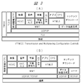
- FIG. 1 An example of the protocol stack of the broadcasting system of the present embodiment is shown in FIG. In the figure, (A) is an example of a protocol stack in a broadcast transmission path, and (B) is an example of a protocol stack in a communication line.
- MMT-SI MMT-Signaling Information
- TLV-SI TLV-Signaling Information
- time information is transmitted in order to provide absolute time.
- MPEG2-TS indicates the component display time based on a different clock for each TS
- MMT indicates the component display time based on the Coordinated Universal Time (UTC).
- UTC Coordinated Universal Time
- the control information includes the TLV-SI related to the TLV multiplexing method for multiplexing IP packets and the MMT that is the media transport method. Prepare the relevant MMT-SI.
- the TLV-SI provides information for the broadcast receiving apparatus 100 to demultiplex the IP packet multiplexed on the broadcast transmission path.
- the TLV-SI is composed of a “table” and a “descriptor”. The “table” is transmitted in the section format, and the “descriptor” is arranged in the “table”.
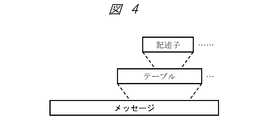
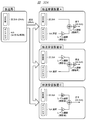
- the MMT-SI is transmission control information indicating information related to the configuration of the MMT package and the broadcast service.
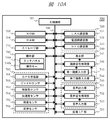
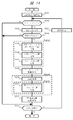
- MMT-SI is composed of three levels: “message” for storing “table” and “descriptor”, “table” having elements and attributes indicating specific information, and “descriptor” indicating more detailed information. Shall. An example of the hierarchical structure of the control information used in the broadcasting system of the present embodiment is shown in FIG.
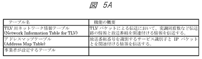
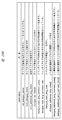
- FIG. 5A shows a list of “tables” used in the TLV-SI of the broadcasting system supported by the broadcast receiving apparatus 100 of the present embodiment.
- the following table is used as a “table” of TLV-SI.
- TLV-NIT The network information table for TLV (Network Information Table for TLV: TLV-NIT) represents information on the physical configuration of the TLV stream transmitted by the network and the characteristics of the network itself.
- AMT Address Map Table
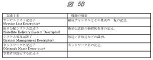
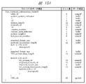
- FIG. 5B shows a list of “descriptors” arranged in the TLV-SI of the broadcasting system to which the broadcast receiving apparatus 100 of the present embodiment corresponds. In this embodiment, the following are used as “descriptors” of TLV-SI.
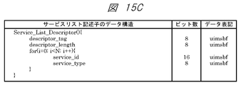
- Service list descriptor The service list descriptor provides a list of services according to service identification and service type.
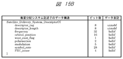
- Satellite distribution system descriptor The satellite distribution system descriptor indicates the physical conditions of the satellite transmission path.
- System management descriptor The system management descriptor is used to identify broadcast and non-broadcast.
- the network name descriptor describes the network name using character codes.
- FIG. 6A shows a list of “messages” used in the MMT-SI of the broadcast system supported by the broadcast receiving apparatus 100 of the present embodiment.
- the following message is used as a “message” of MMT-SI.
- PA message The Package Access (PA) message is used to transmit various tables.
- M2 section message The M2 section message is used to transmit the section extension format of MPEG-2 Systems.
- CA message The CA message is used to transmit a table for identifying the conditional access system.
- M2 short section message is used to transmit the section short format of MPEG-2 Systems.
- the data transmission message is a message for storing a table relating to data transmission.
- FIG. 6B shows a list of “tables” used in the MMT-SI of the broadcast system supported by the broadcast receiving apparatus 100 of the present embodiment.
- the table is control information having elements and attributes indicating specific information, and is stored in a message and transmitted by an MMTP packet.
- the message for storing the table may be determined according to the table.
- the following table is used as the “table” of MMT-SI.
- MPT MMT package table
- the MPT may be stored in the PA message.
- PLT Packet List Table
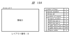
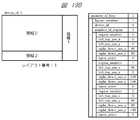
- LCT Layout Configuration Table
- ECM Entity Control Message
- EMM Entity Management Message
- the Entity Management Message transmits individual information including contract information for each subscriber and key information for decrypting ECM (common information).
- the EMM may be stored in the M2 section message.
- CAT Supplemental Access Table: CAT (MH) is used to store a descriptor for identifying a conditional access system.
- CAT (MH) may be stored in the CA message.
- DCM Download Control Message
- the Download Control Message transmits key related information including a key for decrypting a transmission path cipher for downloading.
- the DCM may be stored in the M2 section message.
- DMM Download Management Message transmits key-related information including a download key for decrypting DCM.
- the DMM may be stored in the M2 section message.
- MH-EIT MH-Event Information Table: MH-EIT
- MH-EIT is time-series information regarding events included in each service.
- the MH-EIT may be stored in the M2 section message.
- MH-AIT MH-Application Information Table
- the MH-AIT stores all information related to the application, an activation state required for the application, and the like.
- the MH-AIT may be stored in the M2 section message.
- MH-BIT An MH-Broadcaster Information Table (MH-BIT) is used to present information on broadcasters existing on the network.
- the MH-BIT may be stored in the M2 section message.
- MH-SDTT The MH-software download trigger table (MH-Software Download Trigger Table: MH-SDTT) is used for download notification information.
- the MH-SDTT may be stored in the M2 section message.
- MH-SDT MH-Service Description Table (MH-Service Description Table: MH-SDT) has a sub-table representing a service included in a specific TLV stream, and information related to the organization channel such as the name of the organization channel and the name of the broadcaster. Is transmitted.
- the MH-SDT may be stored in the M2 section message.
- MH-TOT The MH-Time Offset Table (MH-TOT) transmits JST time and date (modified Julian date) information.
- the MH-TOT may be stored in the M2 short section message.
- MH-CDT The MH-Common Data Table (MH-CDT) is used to transmit the common data to be stored in the non-volatile memory in a section format for all receivers that receive the MH-Common Data Table (MH-CDT).
- the MH-CDT may be stored in the M2 section message.
- the data directory management table (Data Directory Management Table: DDM table) provides a directory structure of files constituting an application in order to separate the file structure of the application from the structure for file transmission.
- the DDM table may be stored in the data transmission message.
- DAM table The data asset management table (Data Asset Management Table: DAM table) provides the configuration of the MPU in the asset and version information for each MPU.
- the DAM table may be stored in the data transmission message.
- DCC Table The data content management table (Data Content Configuration Table: DCC table) provides file configuration information as data content in order to realize flexible and effective cache control.
- the DCC table may be stored in the data transmission message.
- EMT Event Message Table
- ⁇ Descriptors used in MMT-SI> 6C and 6D show a list of “descriptors” arranged in the MMT-SI of the broadcasting system to which the broadcast receiving apparatus 100 of the present embodiment corresponds.
- the descriptor is control information that provides more detailed information and is arranged in a table. Note that the table in which the descriptor is arranged may be determined according to the descriptor. In this embodiment, the following are used as “descriptors” of MMT-SI.
- Asset group descriptor provides asset group relationships and priorities within groups.
- the asset group descriptor may be located in the MPT.
- Event package descriptor provides a correspondence between an event representing a program and a package.
- the event package descriptor may be arranged in the MH-EIT transmitted in the M2 section message.
- the background color specification descriptor provides the backmost background color in the layout specification.
- the background color designation descriptor may be arranged in the LCT.
- the MPU presentation area designation descriptor provides a position for presenting an MPU.
- the MPU presentation area designation descriptor may be arranged in the MPT.
- MPU time stamp descriptor indicates the presentation time of the first access unit in the presentation order in the MPU.
- the MPU timestamp descriptor may be located in the MPT.
- the dependency descriptor provides an asset ID of an asset having a dependency relationship.
- the dependency descriptor may be arranged in the MPT.
- Access control descriptor provides information for identifying the conditional access system.
- the access control descriptor may be placed in MPT or CAT (MH).
- the scramble method descriptor provides information for identifying the encryption target and the type of encryption algorithm at the time of scrambling.
- the scrambling scheme descriptor may be arranged in MPT or CAT (MH).
- the message authentication scheme descriptor provides information for identifying the message authentication scheme when performing message authentication.
- the message authentication scheme descriptor may be arranged in MPT or CAT (MH).
- the emergency information descriptor (MH) is used when emergency alert broadcasting is performed.
- the emergency information descriptor (MH) may be located in the MPT.
- the MH-MPEG-4 audio descriptor describes basic information for specifying an encoding parameter of an ISO / IEC 14496-3 (MPEG-4 audio) audio stream. Use for.
- the MH-MPEG-4 audio descriptor may be located in the MPT.
- MH-MPEG-4 Audio Extension Descriptor The MH-MPEG-4 audio extension descriptor is used to describe the profile and level of the MPEG-4 audio stream and settings specific to the encoding method.
- the MH-MPEG-4 audio extension descriptor may be located in the MPT.
- the MH-HEVC video descriptor is an ITU-T recommendation H.264 standard. H.265
- the MH-HEVC video descriptor may be located in the MPT.
- the MH-Link Descriptor identifies a service provided when a viewer requests additional information related to a certain thing described in the program sequence information system.
- the MH-link descriptor may be arranged in MPT, MH-EIT, MH-SDT, etc.
- MH-event group descriptor is used to indicate that these event groups are grouped when there is a relationship between a plurality of events.
- the MH-event group descriptor may be located in the MH-EIT.
- the MH-Service List Descriptor provides a service list according to service identification and service type.
- the MH-service list descriptor may be located in the MH-BIT.
- MH-short format event descriptor represents an event name and a short description of the event in a text format.
- the MH-short form event descriptor may be located in the MH-EIT.
- the MH-extended format event descriptor is used in addition to the MH-short format event descriptor to provide a detailed description of the event.
- the MH-extended event descriptor may be located in the MH-EIT.
- Video Component Descriptor indicates parameters and explanations related to the video component, and is also used to represent an elementary stream in a character format.
- the video component descriptor may be arranged in MPT or MH-EIT.
- the MH-stream identification descriptor is used to label the component stream of the service and to refer to the description content indicated by the video component descriptor in the MH-EIT. .
- the MH-stream identification descriptor may be arranged in the MPT.
- the MH-content descriptor indicates the genre of the event.
- the MH-content descriptor may be located in the MH-EIT.
- the MH-Parental Rate Descriptor represents viewing restrictions based on age, and is used to extend based on other restriction conditions.
- the MH-parental rate descriptor may be located in MPT or MH-EIT.
- the MH-voice component descriptor indicates each parameter of the voice elementary stream, and is also used to represent the elementary stream in a character format.
- the MH-voice component descriptor may be located in MPT or MH-EIT.
- MH Target Area Descriptor
- the MH is used to describe an area targeted by a program or a part of streams constituting the program.
- the MH-target area descriptor may be located in the MPT.
- the MH-series descriptor is used to identify a series program.
- the MH-series descriptor may be located in the MH-EIT.
- the MH-SI transmission parameter descriptor is used to indicate a transmission parameter of SI.
- the MH-SI transmission parameter descriptor may be arranged in the MH-BIT.
- the MH-Broadcaster name descriptor describes the name of the broadcaster.
- the MH-Broadcaster name descriptor may be located in the MH-BIT.
- the MH-Service Descriptor represents the organization channel name and its operator name with a character code together with the service type.
- the MH-service descriptor may be located in the MH-SDT.
- IP Data Flow Descriptor provides information on the IP data flow constituting the service.
- the IP data flow descriptor may be located in MH-SDT.
- the MH-CA activation descriptor describes activation information for activating a CAS program on the CAS infrastructure.
- the MH-CA activation descriptor may be located in MPT or CAT (CA).
- the MH-Type descriptor indicates the type of a file transmitted by the application transmission method.
- the MH-Type descriptor may be placed in the DAM table.
- the MH-Info descriptor describes information related to the MPU or item.
- the MH-Info descriptor may be placed in the DAM table.
- the MH-Expire descriptor describes the expiration date of an item.
- the MH-Expire descriptor may be placed in the DAM table.
- MH-Compression Type descriptor means that the item to be transmitted is compressed, and indicates the compression algorithm and the number of bytes of the item before compression.
- the MH-Compression Type descriptor may be placed in the DAM table.
- the MH-data encoding scheme descriptor is used to identify a data encoding scheme.
- the MH-data encoding scheme descriptor may be arranged in the MPT.
- UTC-NPT Reference Descriptor The UTC-NPT reference descriptor is used to convey the relationship between NPT (Normal Play Time) and UTC.
- the UTC-NPT reference descriptor may be located in the EMT.
- Event message descriptor conveys information related to event messages in general.
- the event message descriptor may be located in the EMT.
- the MH-local time offset descriptor is used to give a certain offset value to the actual time (for example, UTC + 9 hours) and the display time to the human system during the daylight saving time.
- the MH-local time offset descriptor may be located in the MH-TOT.
- the MH-component group descriptor defines and identifies a combination of components in an event.
- the MH-component group descriptor may be located in the MH-EIT.
- the MH-logo transmission descriptor is used to describe a character string for a simple logo, pointing to a CDT format logo, and the like.
- the MH-logo transmission descriptor may be located in the MH-SDT.
- MPU extended time stamp descriptor provides the decoding time of the access unit in the MPU.
- the MPU extended timestamp descriptor may be placed in the MPT.
- MPU download content descriptor is used to describe attribute information of content downloaded using the MPU.
- the MPU download content descriptor may be arranged in MH-SDTT.
- the MH-Network Download Content Descriptor is used to describe attribute information of content downloaded using the network.
- the MH-network download content descriptor may be located in the MH-SDTT.
- the MH-application descriptor describes application information.
- the MH-application descriptor may be located in the MH-AIT.
- the MH-Transmission Protocol Descriptor is used for designating a transmission protocol such as broadcasting or communication and indicating location information of an application depending on the transmission protocol.
- the MH-Transmission Protocol Descriptor may be located in the MH-AIT.
- MH Simple Application Location Descriptor
- the MH is described to indicate details of an application acquisition destination.
- the MH-simple application location descriptor may be located in the MH-AIT.
- the MH-application boundary authority setting descriptor is described in order to set an application boundary and to set a broadcast resource access authority for each area (URL).
- the MH-application boundary authority setting descriptor may be arranged in the MH-AIT.
- the MH-activation priority information descriptor is described for designating the application activation priority.
- the MH-activation priority information descriptor may be arranged in the MH-AIT.
- MH-cache information descriptor The MH-cache information descriptor is described to be used for cache control when the resources constituting the application are cached and held when the application is assumed to be reused. .
- the MH-cache information descriptor may be located in the MH-AIT.
- the MH-Probabilistic Application Delay Descriptor is used to delay the application control timing by a stochastically set delay amount assuming load distribution of server access for application acquisition. Describe in.
- the MH-stochastic application delay descriptor may be placed in the MH-AIT.
- Link destination PU descriptor describes another presentation unit that may transition from the presentation unit (PU).
- the link destination PU descriptor may be arranged in the DCC table.
- Lock cache specification descriptor describes the specification of a file to be cached and locked in the presentation unit.
- the lock cache designation descriptor may be arranged in the DCC table.
- Unlock cache specification descriptor describes the specification of the file to be unlocked among the files locked in the presentation unit.
- the unlock cache specification descriptor may be arranged in the DCC table.
- data transmission can be performed through a plurality of paths such as a TLV stream via a broadcast transmission path and an IP data flow via a communication line.
- the TLV stream includes a TLV-SI such as TLV-NIT or AMT, and an IP data flow that is a data flow of an IP packet.
- the IP data flow includes video assets including a series of video MPUs and audio assets including a series of audio MPUs.
- a subtitle asset including a series of subtitle MPUs, a character super asset including a series of character super MPUs, a data asset including a series of data MPUs, and the like may be included in the IP data flow.
- MPT MMT package table
- the asset that constitutes the package may be only the asset in the TLV stream, but as shown in FIG. 6E, the asset that is transmitted by the IP data flow of the communication line may be included. This is because the location information of each asset included in the package (corresponding to “MMT_general_location_info ()” shown in FIG. 17 to be described later) is included in the MPT, and the broadcast receiving apparatus 100 of the present embodiment specifies the reference destination of each asset. This can be realized by making it possible to grasp.
- the broadcast receiving device 100 can refer to various data transmitted through various transmission paths.
- (1) is an IP data flow received via a digital broadcast signal received by a tuner / demodulator 131 of the broadcast receiving apparatus 100 of FIG.
- the reference destination of (1) may be an IP data flow received by the LAN communication unit 121 described later via the communication line.
- the above (2), (3), (5), and (6) are IP data flows received by the LAN communication unit 121 (described later) via a communication line.
- (4) is a receiving function for receiving a digital broadcast signal using the MMT system and a digital broadcast using the MPEG2-TS system, as in the broadcast receiving apparatus 800 of the second embodiment shown in FIG.
- MMT_general_location_info ()
- MMT_general_location_info ()
- the data constituting the “package” is specified in this way, but in the broadcast system supported by the broadcast receiving apparatus 100 of the present embodiment, a series of data in the “package” unit is converted into the “service” unit of digital broadcasting. Treat as.
- the MPT includes presentation time information (corresponding to the “mpu_presentation_time” parameter shown in FIG. 13B described later) of each MPU specified by the MPT, and a plurality of MPTs specified by the MPT using the presentation time information.
- the MPU can be presented (displayed, output, etc.) in conjunction with a clock based on NTP, which is time information expressed in UTC.
- NTP time information expressed in UTC.
- the “event” is a concept indicating a so-called “program” that is handled by the MH-EIT sent in the M2 section message. Specifically, in the “package” indicated by the event package descriptor stored in the MH-EIT, the duration from the disclosure time stored in the MH-EIT (corresponding to the “start_time” parameter shown in FIG. 21 described later). A series of data included in the period (corresponding to a “duration” parameter shown in FIG. 21 described later) is data included in the concept of the “event”.
- the MH-EIT performs various processes in units of the “event” in the broadcast receiving apparatus 100 according to the present embodiment (for example, program table generation processing, recording reservation and viewing reservation control, copyright management processing such as temporary storage). Can be used.
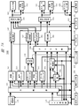
- FIG. 7A is a block diagram illustrating an example of an internal configuration of the broadcast receiving apparatus 100.
- the broadcast receiving apparatus 100 includes a main control unit 101, a system bus 102, a ROM 103, a RAM 104, a storage (storage) unit 110, a LAN communication unit 121, an expansion interface unit 124, a digital interface unit 125, a tuner / demodulation unit 131, and a separation unit 132.
- Video decoder 141 Video decoder 141, video color gamut conversion unit 142, audio decoder 143, character super decoder 144, subtitle decoder 145, subtitle synthesis unit 146, subtitle color gamut conversion unit 147, data decoder 151, cache unit 152, application control unit 153, A browser unit 154, an application color gamut conversion unit 155, a sound source unit 156, a video synthesis unit 161, a monitor unit 162, a video output unit 163, a voice synthesis unit 164, a speaker unit 165, a voice output unit 166, and an operation input unit 170. Is done.
- the main control unit 101 is a microprocessor unit that controls the entire broadcast receiving apparatus 100 according to a predetermined operation program.
- a system bus 102 is a data communication path for transmitting and receiving data between the main control unit 101 and each operation block in the broadcast receiving apparatus 100.
- a ROM (Read Only Memory) 103 is a non-volatile memory in which a basic operation program such as an operating system and other operation programs are stored. For example, a rewritable ROM such as an EEPROM (Electrically Erasable Programmable ROM) or a flash ROM is provided. Used. The ROM 103 may store operation setting values necessary for the operation of the broadcast receiving apparatus 100.
- a RAM (Random Access Memory) 104 serves as a work area for executing a basic operation program and other operation programs. The ROM 103 and the RAM 104 may be integrated with the main control unit 101. Further, the ROM 103 may not use an independent configuration as shown in FIG. 7A but may use a partial storage area in the storage (accumulation) unit 110.
- the storage (accumulation) unit 110 stores an operation program and an operation setting value of the broadcast receiving apparatus 100, personal information of the user of the broadcast receiving apparatus 100, and the like. Further, it is possible to store an operation program downloaded via the Internet 200 and various data created by the operation program. It is also possible to store content such as moving images, still images, and audio obtained from broadcast waves or downloaded via the Internet 200. All or some of the functions of the ROM 103 may be replaced by a partial area of the storage (storage) unit 110. Further, the storage (accumulation) unit 110 needs to hold stored information even when power is not supplied to the broadcast receiving apparatus 100 from the outside. Therefore, for example, a device such as a nonvolatile semiconductor element memory such as a flash ROM or SSD (Solid State Drive), a magnetic disk drive such as an HDD (Hard Disc Drive), or the like is used.
- a nonvolatile semiconductor element memory such as a flash ROM or SSD (Solid State Drive), a magnetic disk drive such as an HDD (Hard Disc Drive), or
- each operation program stored in the ROM 103 or the storage (storage) unit 110 can be added, updated, or expanded in function by download processing from each server device on the Internet 200.
- a LAN (Local Area Network) communication unit 121 is connected to the Internet 200 via the router device 200r, and transmits / receives data to / from each server device and other communication devices on the Internet 200. It is also assumed that an MMT data string (or a part thereof) of a program transmitted via a communication line is acquired.
- the connection with the router device 200r may be a wired connection or a wireless connection such as Wi-Fi (registered trademark).
- the LAN communication unit 121 includes an encoding circuit, a decoding circuit, and the like.
- the broadcast receiving apparatus 100 may further include other communication units such as a BlueTooth (registered trademark) communication unit, an NFC communication unit, and an infrared communication unit.
- the tuner / demodulator 131 receives the broadcast wave transmitted from the radio tower 300t via the antenna 100a, and tunes (tunes) to the channel of the service desired by the user based on the control of the main controller 101. Further, the tuner / demodulator 131 demodulates the received broadcast signal to obtain an MMT data string.
- FIG. 7A a configuration with one tuner / demodulation unit is illustrated. However, for the purpose of simultaneous display of a plurality of screens, back program recording, and the like, the broadcast receiving apparatus 100 includes a tuner / demodulation unit. It is good also as a structure mounted in multiple numbers.
- the separation unit 132 is an MMT decoder, and a video data sequence, an audio data sequence, a character super data sequence, a caption data sequence, etc., which are real-time presentation elements based on a control signal in the input MMT data sequence, are respectively converted into a video decoder 141.
- the voice decoder 143, the character super decoder 144, the subtitle decoder 145, etc. are distributed.
- the data input to the demultiplexing unit 132 includes an MMT data sequence transmitted through a broadcast transmission path and demodulated by the tuner / demodulation unit 131, or MMT data transmitted through a communication line and received by the LAN communication unit 121. It can be a line.
- the separation unit 132 reproduces the multimedia application and file system data that is a component of the multimedia application, and temporarily stores them in the cache unit 152.
- the separation unit 132 extracts general-purpose data and outputs the data to the data decoder 151 for use in streaming data for use with a player that presents data other than video / audio subtitles or data for an application.
- the separation unit 132 may perform error correction, access restriction control, and the like on the input MMT data string based on the control of the main control unit 101.
- the video decoder 141 decodes the video data sequence input from the separation unit 132 and outputs video information.
- the video color gamut conversion unit 142 performs color space conversion processing on the video information decoded by the video decoder 141 as needed for video synthesis processing by the video synthesis unit 161.
- the audio decoder 143 decodes the audio data sequence input from the separation unit 132 and outputs audio information.
- the video decoder 141 and the audio decoder 143 are also supplied with streaming data, such as MPEG-DASH (MPEG-Dynamic Adaptive Streaming HTTP) format, obtained from the Internet 200 via the LAN communication unit 121, for example. good.
- MPEG-DASH MPEG-Dynamic Adaptive Streaming HTTP
- the character super decoder 144 decodes the character super data string input from the separation unit 132 and outputs character super information.
- the caption decoder 145 decodes the caption data string input from the separation unit 132 and outputs caption information.
- the superimposing information output from the character super decoder 144 and the subtitle information output from the subtitle decoder 145 are subjected to the synthesizing process in the subtitle synthesizing unit 146, and further, the subtitle color gamut converting unit 147 performs the synthesis in the video synthesizing unit 161. For the video composition process, a color space conversion process is performed as necessary.
- subtitles those related to the content of the video are referred to as subtitles, and other services are referred to as character supermarkets. To do. If they are not distinguished, they are collectively referred to as subtitles.
- the browser unit 154 transmits the multimedia application file acquired from the server device on the Internet 200 via the cache unit 152 or the LAN communication unit 121 and the file system data that is a component of the multimedia application file to the control information or LAN included in the MMT data string.
- the control information acquired from the server device on the Internet 200 via the communication unit 121 is presented according to an instruction from the application control unit 153 that interprets the control information.
- the multimedia application file may be an HTML (Hyper Text Markup Language) document, a BML (Broadcast Markup Language) document, or the like.
- the application information output from the browser unit 154 is further subjected to color space conversion processing in the application color gamut conversion unit 155 as necessary for the video composition processing in the video composition unit 161.
- the browser unit 154 also plays the application audio information by acting on the sound source unit 156.
- the video composition unit 161 receives the video information output from the video color gamut conversion unit 142, the caption information output from the subtitle color gamut conversion unit 147, the application information output from the application color gamut conversion unit 155, and the like. Processing such as selection and / or superposition is performed.
- the video composition unit 161 includes a video RAM (not shown), and the monitor unit 162 and the like are driven based on video information and the like input to the video RAM. Also, the video composition unit 161 is based on the control of the main control unit 101, and an EPG (Electronic Program Guide) created based on information such as scaling processing and MH-EIT included in the MMT-SI as necessary. Performs superimposition processing of screen information.
- EPG Electronic Program Guide
- the monitor unit 162 is a display device such as a liquid crystal panel, for example, and provides the video information selected and / or superimposed by the video composition unit 161 to the user of the broadcast receiving apparatus 100.
- the video output unit 163 is a video output interface that outputs the video information selected and / or superimposed by the video composition unit 161.
- the presentation function of the broadcast receiving apparatus 100 of the present embodiment has a logical plane structure in order to display the multimedia service as intended by the provider.
- FIG. 7B shows an example of the configuration of the logical plane structure provided in the presentation function of the broadcast receiving apparatus 100 of the present embodiment.
- a character super plane for displaying a character super is arranged on the foreground
- a subtitle plane for displaying a subtitle is arranged on the next layer.
- a multimedia plane for displaying a broadcast video, a multimedia application, or a composite video thereof is arranged, and a background plane is arranged on the back surface.
- the caption synthesizing unit 146 and the video synthesizing unit 161 drawing of the character super information on the character super plane, drawing of the subtitle information on the subtitle plane, and drawing on the multimedia plane such as video information and application information are performed.
- the background color is drawn on the background plane based on LCT included in the MMT-SI. Note that a plurality of multimedia planes in the third layer can be prepared according to the number of video decoders 141. However, even when there are a plurality of multimedia planes, the application information and the like output from the application color gamut conversion unit 155 are output only to the foreground multimedia plane.
- the voice synthesizer 164 receives the voice information output from the voice decoder 143 and the application voice information reproduced by the sound source unit 156, and appropriately performs processing such as selection and / or mixing.
- the speaker unit 165 provides the user of the broadcast receiving apparatus 100 with the audio information that has been selected and / or mixed by the audio synthesis unit 164.
- the audio output unit 166 is an audio output interface that outputs audio information that has been selected and / or mixed by the audio synthesis unit 164.
- the extension interface unit 124 is an interface group for extending the function of the broadcast receiving apparatus 100.
- the extension interface unit 124 includes an analog video / audio interface, a USB (Universal Serial Bus) interface, a memory interface, and the like.
- the analog video / audio interface performs input of analog video signals / audio signals from external video / audio output devices, output of analog video signals / audio signals to external video / audio input devices, and the like.
- the USB interface is connected to a PC or the like to transmit / receive data.
- a broadcast program or content may be recorded by connecting an HDD.
- a keyboard or other USB device may be connected.
- the memory interface transmits and receives data by connecting a memory card and other memory media.
- the digital interface unit 125 is an interface that outputs or inputs encoded digital video data and / or digital audio data.
- the digital interface unit 125 can output the MMT data sequence obtained by demodulation by the tuner / demodulation unit 131, the MMT data sequence obtained via the LAN communication unit 121, or the mixed data of each MMT data sequence as it is. Shall. Further, the MMT data string input from the digital interface unit 125 may be controlled to be input to the separation unit 132. Output of digital content stored in the storage (accumulation) unit 110 or storage of digital content in the storage (accumulation) unit 110 may be performed via the digital interface unit 125.
- the digital interface unit 125 is a DVI terminal, an HDMI (registered trademark) terminal, a Display Port (registered trademark) terminal, or the like, and outputs or inputs data in a format compliant with the DVI specification, the HDMI specification, the Display Port specification, or the like. It may be a thing.
- the data may be output or input in the form of serial data conforming to the IEEE 1394 specification or the like. Further, it may be configured as an IP interface that performs digital interface output via hardware such as Ethernet (registered trademark) or wireless LAN. In this case, the digital interface unit 125 and the LAN communication unit 121 may share the hardware configuration.
- the operation input unit 170 is an instruction input unit that inputs an operation instruction to the broadcast receiving apparatus 100.
- a remote control receiving unit that receives a command transmitted from a remote controller (not shown) and a button switch are arranged. It shall consist of operation keys. Either one may be sufficient.
- the operation input unit 170 may be replaced with a touch panel arranged on the monitor unit 162.
- a keyboard connected to the extension interface unit 124 may be substituted.
- the remote controller (not shown) may be replaced with a portable information terminal 700 having a remote command transmission function.
- the broadcast receiving apparatus 100 when the broadcast receiving apparatus 100 is a television receiver or the like, the video output unit 163 and the audio output unit 166 are not essential components of the present invention.
- the broadcast receiving apparatus 100 may be an optical disk drive recorder such as a DVD (Digital Versatile Disc) recorder, a magnetic disk drive recorder such as an HDD recorder, an STB (Set Top Box), or the like. It may be a PC (Personal Computer), a tablet terminal, a navigation device, a game machine or the like having a digital broadcast receiving function or a broadcast communication cooperation function.
- the monitor unit 162 and the speaker unit 165 may not be provided.
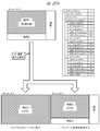
- FIG. 7C is an example of a system configuration of clock synchronization / presentation synchronization in a broadcast system supported by the broadcast receiving apparatus 100 of the present embodiment.
- UTC is transmitted from the broadcast transmission system to a receiver (such as the broadcast receiving device 100 of the present embodiment) in the 64-bit NTP timestamp format.
- NTP timestamp format “seconds or more” of UTC is represented by 32 bits, and “less than seconds” is represented by 32 bits.
- a system clock for synchronizing the video system and a system clock for operating an NTP clock for example, as shown in the figure, “2 24” Hz (about 16.8 MHz)
- the frequency may be used.
- the system clock in the conventional broadcasting system was 27 MHz and the hardware configuration of the receiver can be easily constructed, the number of "2 24" to "2 28" It is desirable to employ a power frequency as the system clock.
- the system clock is set to a power of 2 such as “2 24” to “2 28” as described above on the broadcast transmission system side or the receiver side, it is received from the broadcast transmission system side.
- a PLL system On the broadcast transmission system side, when time information in NTP format is obtained from the outside, a PLL system is configured with a 32 + n-bit counter by a VCO (Voltage Controlled Oscillator) of “2 to the power of 2” Hz, and the time information given from the outside Realizing a synchronized sending system clock. Further, the entire signal processing system is operated in synchronization with a system clock of “2 to the power of n” Hz. Further, the output of the transmission system clock is periodically transmitted to the receiver side through the broadcast transmission path as time information in the NTP length format.
- VCO Voltage Controlled Oscillator
- time information in the NTP length format is received via the broadcast transmission path, and the reception system clock is reproduced by a PLL system based on a VCO of “2n” Hz, similarly to the broadcast transmission system side.
- the reception system clock becomes a clock synchronized with the broadcast transmission system side.
- the signal processing system of the receiver in synchronization with the system clock of “2 to the power of n” Hz, clock synchronization between the broadcast transmission system side and the receiver side is realized, and stable signal reproduction is possible.
- the decoding time and the presentation time for each presentation unit of the video / audio signal are set on the broadcast transmission system side based on the time information in the NTP format.
- the MPT time stamp descriptor shown in FIG. 13B described later is stored in the MPT stored in the PA message transmitted by the broadcast signal.
- the “mpu_sequence_number (MPU sequence number)” parameter in the MPU time stamp descriptor of FIG. 13B indicates the sequence number of the MPU describing the time stamp
- the “mpu_presentation_time (MPU presentation time)” parameter indicates the MPU presentation time in 64-bit NTP. It is shown in time stamp format. Therefore, the receiver can refer to the MPU time stamp descriptor stored in the MPT and control the presentation (display, output, etc.) timing for each MPU such as a video signal, an audio signal, a caption, and a character supermarket. .
- the video / audio signal is synchronized even with a clock of about "2 to the 16th power" Hz (about 65.5 KHz).
- a clock of “2 to the power of m” generated by dividing the system clock is used to control the decoding timing and presentation timing
- the “32-m” bit need not be referenced. Therefore, the lower “32-m” bits of the NTP timestamp format described in the MPU timestamp descriptor or the like may be fixed to “0” or “1”.
- FIG. 7D is a software configuration diagram of the broadcast receiving apparatus 100 according to the present embodiment, and illustrates a software configuration in the ROM 103, the RAM 104, and the storage (storage) unit 110.
- a basic operation program 1001 and other operation programs are stored in the ROM 103
- a reception function program 1002 and other operation programs are stored in the storage (accumulation) unit 110.
- the storage unit 110 also stores a content storage area 1200 that stores content such as moving images, still images, and audio, and authentication information that is necessary when accessing an external mobile terminal device or each server device. It is assumed that an information storage area 1300 and various information storage areas for storing various other information are provided.
- the basic operation program 1001 stored in the ROM 103 is expanded in the RAM 104, and the main control unit 101 executes the expanded basic operation program to constitute a basic operation execution unit 1101.
- the reception function program 1002 stored in the storage (accumulation) unit 110 is also expanded in the RAM 104, and the main control unit 101 executes the expanded reception function program to configure the reception function execution unit 1102. To do.
- the RAM 104 is provided with a temporary storage area that temporarily holds data created when each operation program is executed as necessary.
- the main control unit 101 executes the basic operation processing to control each operation block by expanding the basic operation program 1001 stored in the ROM 103 into the RAM 104 and executing it.
- the unit 1101 is described as performing control of each operation block. The same description is made for other operation programs.
- the reception function execution unit 1102 controls each operation block of the broadcast receiving apparatus 100 in order to reproduce components such as video and audio transmitted in the broadcast system of the present embodiment.
- the transport processing unit 1102a mainly controls the MMT decoder function of the separation unit 132, and distributes the video data sequence, the audio data sequence, and the like separated from the MMT data sequence to the corresponding decoding processing units.
- the AV decoding processing unit 1102b mainly controls the video decoder 141, the audio decoder 143, and the like.
- the application processing unit 1102c mainly controls the cache unit 152, the application control unit 153, the browser unit 154, and the sound source unit 156.
- the character super processing unit 1102d mainly controls the character super decoder 144.
- the caption processing unit 1102e mainly controls the caption decoder 145.
- the general-purpose data processing unit 1102f mainly controls the data decoder 151.
- the EPG generation unit 1102g generates an EPG screen by interpreting description contents such as MH-EIT included in the MMT-SI.
- the presentation processing unit 1102h is based on the logical plane structure, and the video color gamut conversion unit 142, the subtitle synthesis unit 146, the subtitle color gamut conversion unit 147, the application color gamut conversion unit 155, the video synthesis unit 161, and the audio synthesis unit 164. Is mainly controlled.
- the operation programs may be stored in advance in the ROM 103 and / or the storage (storage) unit 110 at the time of product shipment. It may be acquired from the other application server 500 on the Internet 200 via the LAN communication unit 121 after the product is shipped. Further, each operation program stored in a memory card, an optical disk or the like may be acquired via the expansion interface unit 124 or the like.
- FIG. 8 is a block diagram illustrating an example of the internal configuration of the broadcast station server 300.
- the broadcast station server 300 includes a main control unit 301, a system bus 302, a RAM 304, a storage unit 310, a LAN communication unit 321 and a digital broadcast signal transmission unit 360.
- the main control unit 301 is a microprocessor unit that controls the entire broadcast station server 300 in accordance with a predetermined operation program.
- a system bus 302 is a data communication path for performing data transmission / reception between the main control unit 301 and each operation block in the broadcast station server 300.
- the RAM 304 serves as a work area when executing each operation program.
- the storage unit 310 stores a basic operation program 3001, a broadcast content management / distribution program 3002, and a broadcast content transmission program 3003, and further includes a broadcast content storage area 3200 and a metadata storage area 3300.
- the broadcast content storage area 3200 stores program content and the like of each broadcast program broadcast by the broadcast station.
- the metadata storage area 3300 stores metadata such as the program title, program ID, program overview, performers, broadcast date and time, copy control information related to each program content, and the like of each broadcast program.
- the basic operation program 3001, the broadcast content management / distribution program 3002, and the broadcast content transmission program 3003 stored in the storage unit 310 are expanded in the RAM 304, and the main control unit 301 further executes the expanded programs.
- a basic operation execution unit 3101, a broadcast content management / distribution execution unit 3102, and a broadcast content transmission execution unit 3103 are configured.
- the broadcast content management / distribution execution unit 3102 manages the program content and the like of each broadcast program stored in the broadcast content storage area 3200 and the metadata storage area 3300, the program content of each broadcast program, and the like. Performs control when providing metadata to service providers based on contracts. Furthermore, the broadcast content management / distribution execution unit 3102 provides a service provider based on the contract as necessary when providing the program content of each broadcast program and each metadata to the service provider. Authentication processing of the server 400 may be performed.
- the broadcast content transmission execution unit 3103 displays the program content of the broadcast program stored in the broadcast content storage area 3200, the program title of the broadcast program stored in the metadata storage area 3300, the program ID, copy control information of the program content, and the like. Time schedule management and the like are performed when an MMT data string including the MMT data string is transmitted from the radio tower 300t via the digital broadcast signal transmission unit 360.
- the LAN communication unit 321 is connected to the Internet 200 and communicates with the service provider server 400 on the Internet 200.
- the LAN communication unit 321 includes a coding circuit, a decoding circuit, and the like.
- the digital broadcast signal transmission unit 360 modulates the MMT data sequence composed of the video data sequence, the audio data sequence, the program information data sequence, etc. of the program content of each broadcast program stored in the broadcast content storage area 3200.
- the digital broadcast wave is transmitted through the radio tower 300t.
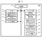
- FIG. 9 is a block diagram illustrating an example of the internal configuration of the service provider server 400.
- the service provider server 400 includes a main control unit 401, a system bus 402, a RAM 404, a storage unit 410, and a LAN communication unit 421.
- the main control unit 401 is a microprocessor unit that controls the entire service provider server 400 according to a predetermined operation program.
- a system bus 402 is a data communication path for transmitting and receiving data between the main control unit 401 and each operation block in the service provider server 400.
- the RAM 404 becomes a work area when each operation program is executed.
- the storage unit 410 stores a basic operation program 4001, a video content management / distribution program 4002, and an application management / distribution program 4004, and further stores a video content storage area 4200, a metadata storage area 4300, an application storage area 4400, and user information storage.
- An area 4500 is provided.
- the video content storage area 4200 stores program content of a broadcast program provided from the broadcast station server 300 as video content.
- the video content produced by the service provider is stored.
- the metadata storage area 4300 stores each metadata provided from the broadcast station server 300, metadata about video content produced by the service provider, and the like.
- the application storage area 4400 stores various applications for realizing a service linked to a broadcast program for distribution in response to a request from each television receiver.
- the user information storage area 4500 stores information (such as personal information and authentication information) related to users who are permitted to access the service provider server 400.
- the basic operation program 4001, the video content management / distribution program 4002 and the application management / distribution program 4004 stored in the storage unit 410 are expanded in the RAM 404, and the main control unit 401 further expands the basic operation program and video.
- a basic operation execution unit 4101, a video content management / distribution execution unit 4102, and an application management / distribution execution unit 4104 are configured.
- the video content management / distribution execution unit 4102 obtains the program content and metadata of the broadcast program from the broadcast station server 300, the video content stored in the video content storage area 4200 and the metadata storage area 4300, and each metadata. And the distribution of the video content etc. and each metadata to each television receiver. Furthermore, the video content management / distribution execution unit 4102 performs authentication processing and the like of each television receiver as necessary when delivering each video content and each metadata to each television receiver. You can go.
- the application management / distribution execution unit 4104 performs management of each application stored in the application storage area 4400 and control when each application is distributed in response to a request from each television receiver. Furthermore, the application management / distribution execution unit 4104 may perform authentication processing of each television receiver as necessary when distributing each application to each television receiver.
- the LAN communication unit 421 is connected to the Internet 200 and communicates with the broadcast receiving device 100 via the broadcast station server 300 on the Internet 200 and the router device 200r.
- the LAN communication unit 421 includes a coding circuit, a decoding circuit, and the like.
- FIG. 10A is a block diagram illustrating an example of the internal configuration of the portable information terminal 700.
- the portable information terminal 700 includes a main control unit 701, a system bus 702, a ROM 703, a RAM 704, a storage unit 710, a communication processing unit 720, an expansion interface unit 724, an operation unit 730, an image processing unit 740, an audio processing unit 750, and a sensor unit 760. , Is composed.
- the main control unit 701 is a microprocessor unit that controls the entire portable information terminal 700 according to a predetermined operation program.
- a system bus 702 is a data communication path for transmitting and receiving data between the main control unit 701 and each operation block in the portable information terminal 700.
- the ROM 703 is a memory in which a basic operation program such as an operating system and other operation programs are stored. For example, a rewritable ROM such as an EEPROM or a flash ROM is used.
- the RAM 704 serves as a work area when the basic operation program and other operation programs are executed.
- the ROM 703 and the RAM 704 may be integrated with the main control unit 701. Further, the ROM 703 does not have an independent configuration as shown in FIG. 10A, and may use a partial storage area in the storage unit 710.
- the storage unit 710 stores an operation program and an operation setting value of the portable information terminal 700, personal information of the user of the portable information terminal 700, and the like. Further, it is possible to store an operation program downloaded via the Internet 200 and various data created by the operation program. In addition, contents such as moving images, still images, and audio downloaded via the Internet 200 can be stored. All or part of the functions of the ROM 703 may be replaced by a partial area of the storage unit 710. In addition, the storage unit 710 needs to hold stored information even when power is not supplied to the portable information terminal 700 from the outside. Therefore, for example, a device such as a nonvolatile semiconductor element memory such as a flash ROM or SSD, a magnetic disk drive such as an HDD, or the like is used.
- operation programs stored in the ROM 703 and the storage unit 710 can be added, updated, and expanded in function by download processing from each server device on the Internet 200.
- the communication processing unit 720 includes a LAN communication unit 721, a mobile telephone network communication unit 722, and an NFC communication unit 723.
- the LAN communication unit 721 is connected to the Internet 200 via the router device 200r and the access point 200a, and transmits / receives data to / from each server device and other communication devices on the Internet 200. It is assumed that connection with the router device 200r and the access point 200a is performed by wireless connection such as Wi-Fi (registered trademark).
- the mobile telephone network communication unit 722 performs telephone communication (call) and data transmission / reception by wireless communication with the base station 600b of the mobile telephone communication network.
- the NFC communication unit 723 performs wireless communication when close to the corresponding reader / writer.
- the LAN communication unit 721, the mobile telephone network communication unit 722, and the NFC communication unit 723 are each provided with a coding circuit, a decoding circuit, an antenna, and the like.
- the communication processing unit 720 may further include another communication unit such as a BlueTooth (registered trademark) communication unit or an infrared communication unit.
- the extended interface unit 724 is an interface group for extending the functions of the portable information terminal 700, and in this embodiment, is configured by a video / audio interface, a USB interface, a memory interface, and the like.
- the video / audio interface performs input of video signals / audio signals from external video / audio output devices, output of video signals / audio signals to external video / audio input devices, and the like.
- the USB interface is connected to a PC or the like to transmit / receive data. A keyboard or other USB device may be connected.
- the memory interface transmits and receives data by connecting a memory card and other memory media.
- the operation unit 730 is an instruction input unit that inputs an operation instruction to the portable information terminal 700.
- the operation unit 730 includes a touch panel 730t arranged on the display unit 741 and an operation key 730k in which button switches are arranged. Shall. Either one may be sufficient.
- the portable information terminal 700 may be operated using a keyboard or the like connected to the extension interface unit 724.
- the portable information terminal 700 may be operated using a separate terminal device connected by wired communication or wireless communication. That is, the portable information terminal 700 may be operated from the broadcast receiving device 100.
- the touch panel function may be provided in the display unit 741.
- the image processing unit 740 includes a display unit 741, an image signal processing unit 742, a first image input unit 743, and a second image input unit 744.
- the display unit 741 is a display device such as a liquid crystal panel, for example, and provides the image data processed by the image signal processing unit 742 to the user of the portable information terminal 700.
- the image signal processing unit 742 includes a video RAM (not shown), and the display unit 741 is driven based on the image data input to the video RAM.
- the image signal processing unit 742 has a function of performing format conversion, menu and other OSD (On Screen Display) signal superimposing processing as necessary.
- the first image input unit 743 and the second image input unit 744 convert light input from the lens into an electrical signal using an electronic device such as a CCD (Charge Coupled Device) or a CMOS (Complementary Metal Oxide Semiconductor) sensor.
- an electronic device such as a CCD (Charge Coupled Device) or a CMOS (Complementary Metal Oxide Semiconductor) sensor.
- a camera unit for inputting image data of surroundings and objects.
- the audio processing unit 750 includes an audio output unit 751, an audio signal processing unit 752, and an audio input unit 753.
- the audio output unit 751 is a speaker, and provides the audio signal processed by the audio signal processing unit 752 to the user of the portable information terminal 700.
- the voice input unit 753 is a microphone, and converts a user's voice and the like into voice data and inputs the voice data.
- the sensor unit 760 is a sensor group for detecting the state of the portable information terminal 700.
- the portable information terminal 700 may further include other sensors such as a barometric pressure sensor.
- the portable information terminal 700 may be a mobile phone, a smart phone, a tablet terminal, or the like. It may be a PDA (Personal Digital Assistant) or a notebook PC. Further, it may be a digital still camera, a video camera capable of shooting moving images, a portable game machine, a navigation device, or other portable digital devices.
- PDA Personal Digital Assistant
- notebook PC Portable Computer System
- the configuration example of the portable information terminal 700 illustrated in FIG. 10A includes a number of configurations that are not essential to the present embodiment, such as the sensor unit 760, but the present embodiment may be configured without these components. There is no loss of effect. Further, a configuration not shown in the figure such as a digital broadcast receiving function and an electronic money settlement function may be further added.
- FIG. 10B is a software configuration diagram of the portable information terminal 700 of the present embodiment, and shows a software configuration in the ROM 703, the RAM 704, and the storage unit 710.
- a basic operation program 7001 and other operation programs are stored in the ROM 703, and a cooperation control program 7002 and other operation programs are stored in the storage unit 710.
- the storage unit 710 includes a content storage area 7200 for storing contents such as moving images, still images, and audio, an authentication information storage area 7300 for storing authentication information necessary for accessing the television receiver and each server device, It is assumed that various information storage areas for storing other various information are provided.
- the basic operation program 7001 stored in the ROM 703 is expanded in the RAM 704, and the main control unit 701 executes the expanded basic operation program to constitute a basic operation execution unit 7101.
- the cooperative control program 7002 stored in the storage unit 710 is also expanded in the RAM 704, and the main control unit 701 executes the expanded cooperative control program to configure the cooperative control execution unit 7102.
- the RAM 704 includes a temporary storage area that temporarily stores data created when each operation program is executed as necessary.
- the main control unit 701 executes the basic operation execution by executing the basic operation program 7001 stored in the ROM 703 by expanding the basic operation program 7001 in the RAM 704 and executing it. It is described that the unit 7101 controls each operation block. The same description is made for other operation programs.
- the cooperation control execution unit 7102 performs management such as device authentication and connection, transmission / reception of each data, and the like when the portable information terminal 700 performs a link operation with the television receiver.
- the cooperation control execution unit 7102 includes a browser engine function for executing an application that works in conjunction with the television receiver.
- the operation programs may be stored in advance in the ROM 703 and / or the storage unit 710 at the time of product shipment. After the product is shipped, it may be acquired from another application server 500 on the Internet 200 via the LAN communication unit 721 or the mobile telephone network communication unit 722. Further, each operation program stored in a memory card, an optical disk, or the like may be acquired via the expansion interface unit 724 or the like.
- the broadcast receiving apparatus of this embodiment has two types of time management functions.
- the first time management function is a time management function based on NTP, as already described with reference to FIG. 7C.
- the second time management function is a time management function based on the MH-TOT, and is a time managed based on the time information transmitted by the MH-TOT described with reference to FIG. 6B.
- FIG. 13A An example of the configuration of time information transmitted by NTP is shown in FIG. 13A.
- FIG. 13B An example of the data structure of the MPU time stamp descriptor is shown in FIG. 13B.
- the “reference_timestamp” parameter, the “transmit_timestamp” parameter, etc. in the NTP format are time data in a 64-bit length NTP length format
- the “mpu_presentation_time” parameter in the MPU time stamp descriptor is also a 64-bit length NTP timestamp. Format time data.
- the time data in the NTP length format and the time data in the NTP timestamp format are data in which “seconds or more” of UTC is represented by 32 bits and “sub-seconds” is represented by 32 bits.
- time information up to “less than second” can be transmitted as time information in the NTP format.
- time information in the NTP format is expressed in UTC, unlike the conventional clock management in digital broadcasting, as shown in FIG. 3B, a communication line path (for example, communication that can be received by the LAN communication unit 121 in FIG. 7A). It is possible to match with NTP included in a signal received via a line.
- the information transmitted by MH-TOT is as follows. It is assumed that the broadcast receiving apparatus 100 can acquire the current date and Japan standard time by MH-TOT.
- FIG. 11A shows an example of the data structure of the MH-TOT.
- the broadcast receiving apparatus 100 can acquire the current date and time from the “JST_time” parameter of the MH-TOT.
- the “JST_time” parameter includes the lower 16 bits of the encoded data of the current date based on the modified Julian Date (Modified Julian Date: MJD) and six standard times (Japan Standard Time: JST). Assume that it includes 24-bit information expressed in binary-coded decimal (BCD).
- the difference between the time based on NTP and the time based on MH-TOT is the information in UTC notation that the former NTP can transmit time information up to “less than second” as described above, whereas MH ⁇
- the information transmitted by TOT is information up to “second unit” in JST notation.
- the broadcast receiving apparatus 100 has a time management function based on NTP, which is time information expressed in UTC, and decodes and synchronizes display of video, audio, subtitles, text super, and other presentation data that are broadcast signal contents. As a result, it is possible to realize a more accurate synchronization process. Furthermore, by referring to information in UTC notation instead of clock notation of the broadcasting station, video, audio, subtitles, superimposing characters, or other data, which is the content of the broadcast signal received by the broadcast signal, is acquired through the communication line route. Decoding and display synchronization processing with video, audio, subtitles, superimpose characters, or other data can also be performed.
- the broadcast receiving apparatus of the present embodiment provides a time management function based on “JST_time” including 24-bit information represented by six 4-bit binary-coded decimal numbers of MH-TOT, and presents the current time to the user.
- the process may be used for each process that handles the MH-event information table (MH-EIT) described in FIG. 6B.
- MH-EIT MH-event information table
- each time information described in the MH-event information table (MH-EIT) is represented by six 4-bit binary-coded decimal numbers in the same manner as the EIT of the conventional digital broadcast transmitted by the MPEG2-TS system.
- the 24-bit information is stored in “decimal” two-digit “hour”, “minute”, and “second”. For this reason, the time management function based on the MH-TOT in the broadcast receiving apparatus 100 of the present embodiment is easily consistent with the process using the MH-EIT.
- the process using the MH-EIT includes a program table generation process (described later), a recording reservation and viewing reservation control, a copyright management process such as temporary storage, and the like. This is because the accuracy of subseconds is rarely required for any processing, and accuracy in units of one second is sufficient.
- copyright management processing such as program table generation processing, recording reservation and viewing reservation control, and temporary storage is a function that is also installed in a receiver of a conventional digital broadcasting system using the MPEG2-TS system.
- the conventional MPEG2-TS digital broadcasting system can be used for processing such as program guide generation processing, recording reservation and viewing reservation control, copyright management processing such as temporary storage, etc. If it is configured so that it can be handled by consistent time management processing, a broadcast receiving apparatus having both a conventional MPEG2-TS digital broadcast reception function and an MMT digital broadcast reception function is configured. In these processes (program table generation processing, recording reservation and viewing reservation control, copyright management processing such as temporary storage, etc.), it is not necessary to design a processing algorithm separately, thereby reducing costs. can do.
- the broadcast receiving apparatus 100 includes a time management function using two types of time information with different accuracy.
- One time information is notation time information consistent with the conventional digital broadcasting system, and the other time information is time information with higher resolution than the one time information.
- the former time information can be used for program schedule generation processing, recording reservation and viewing reservation control, temporary storage, etc.
- the broadcast receiving apparatus can be provided at low cost.
- the broadcast receiving apparatus 100 can achieve both higher-level information presentation processing and cost reduction by providing the two types of time management functions described above.
- the broadcast receiving apparatus 100 in order to increase the accuracy of the management time of the time management function based on NTP already described with reference to FIG. 7C, from the time management server (not shown) or the broadcast station server 300 to the broadcast receiving device 100.
- the information related to the estimated delay time in the time information transmission is transmitted by including in the broadcast signal, and the broadcast receiving apparatus 100 is configured to use the information related to the estimated delay time to correct the system clock of the time management function based on NTP. Also good.
- the information on the estimated delay time may be transmitted within the TMCC (Transmission and Multiplexing Configuration Control) area outside the TLV multiplexed stream, not within the TLV multiplexed stream shown in FIG. good.
- the broadcast receiving apparatus 100 can extract information on the estimated delay time without going through a TLV multiplexed stream separation process (demux process). That is, it is possible to acquire information that is not easily affected by the delay caused by the separation process in the broadcast receiving apparatus 100, and therefore it is possible to perform a highly accurate system clock correction process.
- TLV multiplexed stream separation process tandem process
- the time information may be stored in the TMCC extended information area and transmitted.
- the “delta” parameter is a 32-bit transmission delay value from the time management server that distributes the UTC or the server device that generates the TMCC signal to the general broadcast receiving device. It is expressed with a signed fixed point.
- the upper 16 bits describe the integer part and the lower 16 bits describe the decimal part.
- the “transmit_timestamp” parameter is a transmission time stamp, and describes the time when the TMCC signal is transmitted from the server device in the NTP time stamp length format.
- the upper 32 bits represent the integer part, and the lower 32 bits represent the decimal part.
- the broadcast receiving apparatus 100 includes information related to the assumed delay time described in the time information stored and transmitted in the TMCC extended information area (for example, the above-described “delta”).
- the system clock of the time management function based on the NTP used for the synchronization processing of each content data of the broadcast signal can be corrected with higher accuracy.
- the broadcast receiving apparatus 100 of the present embodiment has a time management function for acquiring the current date and the Japan standard time based on information transmitted by the MH-TOT and managing the time.
- the current date and Japan standard time acquired by the information transmitted by the MH-TOT are superimposed on the video information, application information, and the like by the video composition unit 161 of the broadcast receiving apparatus 100, thereby being displayed on the monitor unit 162 and the video output unit 163. It can be output and provided to the user.
- the MH-TOT has the data structure shown in FIG. 11A, and the broadcast receiving apparatus 100 can acquire the current date and current time from the “JST_time” parameter of the MH-TOT.
- the date after “April 23, 2038” is expressed by switching the calculation method between the case where the value of MJD is greater than or equal to the predetermined value and the case where it is less than the predetermined value. It shall be controlled as possible.
- FIG. 12 shows an example of the first calculation method used when the MJD value is greater than or equal to a predetermined value and the second calculation method used when the MJD value is less than the predetermined value.
- the predetermined value is “32768 (0x8000)”
- the MJD is “32768” or more
- the current date is calculated using the first calculation method
- the MJD is less than “32768”.
- the case where MJD is less than “32768” is equivalent to the case where the most significant bit of 16-bit data of MJD is “0”. Thereby, in the broadcast receiving apparatus 100 of the present embodiment, it is possible to represent dates after “April 23, 2038”.
- the predetermined value can be arbitrarily set, and the predetermined value may be set to “16384 (0x4000)”, “49152 (0xC000)”, or the like.
- the calculation method switching condition may be that the upper 2 bits of the 16-bit data of MJD are “00” and the upper 2 bits of the 16-bit data of MJD are not “11”.
- the “reserved” parameter in the MH-TOT data structure shown in FIG. You may make it switch said 1st calculation method and said 2nd calculation method according to the flag which replaced a part or all, or the newly added flag. For example, when the most significant bit of MJD 16-bit encoded data is “0”, the flag is set to “1” if the MJD indicates “April 23, 2038” or later. If it does not indicate “April 23, 2038” or later, “0” may be set. When the flag is “1”, the second calculation method shown in FIG. 12 may be used, and when the flag is “0”, the first calculation method may be used. Alternatively, a descriptor having the same meaning as the flag may be newly prepared and arranged in the MH-TOT.
- the broadcast system of this embodiment transmits NTP format absolute time
- the broadcast receiving apparatus 100 of this embodiment has a time management function based on the NTP.
- the decoding timing and presentation for each presentation unit of the video / audio signal are referred to by referring to the NTP timestamp described in the MPU timestamp descriptor set for each MPU.
- the timing is controlled.
- the time information in the NTP format has the configuration shown in FIG. 13A.
- the MPU time stamp descriptor has the configuration shown in FIG. 13B.
- the “reference_timestamp” parameter, the “transmit_timestamp” parameter, the “mpu_presentation_time” parameter, or the like is referred to, and the first reference is made according to the value of the referenced time data or the like.
- the calculation methods and the second calculation method may be selected. That is, for example, when the most significant bit of the 64-bit time data in the NTP length format is “0”, the second calculation method is used, and when it is not “0”, the first calculation method is used. And so on.
- the broadcast receiving apparatus 100 can represent dates after “April 23, 2038”.
- the AMT of the broadcasting system provides a list of multicast groups of IP packets for receiving IP packets transmitted by the TLV multiplexing method as distinctly as possible from IP packets transmitted through a communication line. Shall. It is possible to list a plurality of IP multicast groups in one service identification. In addition, an address mask can be used to efficiently describe successive IP addresses.
- a list of services acquired from the TLV-NIT is stored in a nonvolatile memory such as the ROM 103 or the storage unit 110 at the time of channel scanning at the time of initial setting or at the time of rescanning for setting change.
- a list of IP multicast groups corresponding to the services can be stored in the nonvolatile memory in association with the services as IP related information. To do.
- FIG. 14 is a diagram showing an example of an operation sequence at the time of channel scanning (rescanning) in the broadcast receiving apparatus 100 of the present embodiment.
- the reception function execution unit 1102 sets an initial frequency value to the tuner / demodulation unit 131 and instructs the tuner / demodulation unit 131 to perform tuning to the frequency value (S101).
- the reception function execution unit 1102 next acquires TLV-NIT from the received signal (S103).
- the reception function execution unit 1102 acquires information such as a TLV stream ID and an original network ID from the acquired TLV-NIT. (S105).
- FIG. 15A shows an example of the data structure of TLV-NIT.
- the TLV stream ID information can be acquired from the “tlv_stream_id” parameter, and the original network ID information can be acquired from the “original_network_id” parameter.
- distribution system information regarding the physical conditions of the broadcast transmission path corresponding to each TLV stream ID / original network ID is acquired from the distribution system descriptor (S106), and a list of service IDs is acquired from the service list descriptor ( S107).
- FIG. 15B shows an example of the data structure of the satellite distribution system descriptor.
- FIG. 15C shows an example of the data structure of the service list descriptor.
- the reception function execution unit 1102 acquires the AMT from the received signal (S109), and further acquires a list of IP multicast groups related to each service ID stored in the service list (S110).
- FIG. 15D shows an example of the data structure of AMT. If the AMT has a list of IP multicast groups related to a plurality of service IDs, the process of S110 is repeated. If there are a plurality of AMTs having a list of IP multicast groups related to different service IDs, the processes of S109 to S110 are repeated.
- the reception function executing unit 1102 stores the IP multicast group list acquired in the processing of S110 as IP related information in association with the service ID in the ROM 103 or the storage unit 110 (updated when rescanning). (S111).
- tuner / demodulator 131 If the tuner / demodulator 131 has not successfully locked to the set frequency value in the process of S102 (S102: No), and the TLV-NIT acquired in the process of S103 is not valid data. In the case (S104: No), the processing of S105 to S111 is not performed.
- the reception function execution unit 1102 ends the processing if the frequency value set in the tuner / demodulation unit 131 is the final frequency value in the channel scan range (S112: Yes). On the other hand, if the set frequency value is not the final frequency value in the channel scan range (S112: No), the frequency value set in the tuner / demodulator 131 is increased (S113), and the processing of S102 to S111 is performed. repeat. Note that if one TLV-NIT can acquire service IDs for all the services constituting the broadcast network and further can acquire an AMT having a list of IP multicast groups related to the service IDs, S112 to S113 No processing is required.
- the broadcast receiving apparatus 100 is able to create a list of services (service list) that configure the broadcast network at the time of channel scanning at the time of initial setting or at the time of rescanning for setting change. Simultaneously with the creation / update, a list of IP multicast groups (IP related information) corresponding to each service can be created / updated, and further stored in a non-volatile memory such as the ROM 103 or the storage unit 110.
- a list of services (service list) that configure the broadcast network at the time of channel scanning at the time of initial setting or at the time of rescanning for setting change.
- IP multicast groups IP related information
- the rescan for changing the setting is automatically performed when it is detected that the information in the table has changed by referring to the “version_number” parameter of TLV-NIT or AMT. May be.
- the “version_number” parameter of one of TLV-NIT and AMT is detected, only information relating to the table in which the change in the parameter is detected may be automatically updated.
- the automatic update described above it is desirable to notify the user that the rescan has been automatically performed.
- the user may be notified that information in the table has changed, and the user may be allowed to select whether or not to perform the rescan.
- FIG. 16 is a diagram illustrating an example of an operation sequence at the time of channel selection (channel switching) in the broadcast receiving apparatus 100 according to the present embodiment.
- reception function execution unit 1102 interprets the command transmitted from the remote controller and designates the service ID of the target service (S201). Next, reception function execution section 1102 starts acquiring AMT from the received signal of tuner / demodulation section 131. If acquisition of the AMT is successful within a predetermined time (S202: Yes), information on a list of IP multicast groups corresponding to the service ID is acquired from the acquired AMT (S204). On the other hand, if acquisition of the AMT is not successful within a predetermined time (S202: No), the IP corresponding to the service ID is referred to by referring to the IP related information stored in the ROM 103 or the storage unit 110 (S203). Information on the list of multicast groups is acquired (S204). Note that the IP-related information stored in the ROM 103 or the storage unit 110 may always be referred to without performing the determination process of S202.
- the reception function execution unit 1102 starts acquiring TLV-NIT from the reception signal of the tuner / demodulation unit 131.
- distribution system information for acquiring an IP data flow corresponding to the service ID is acquired from the acquired TLV-NIT (S207).
- the service ID stored in the ROM 103 or the storage unit 110 is referred to (S206), and the service ID is supported.
- Distribution system information for acquiring an IP data flow is acquired (S207).
- the service list stored in the ROM 103 or the storage unit 110 may always be referred to without performing the determination process of S205.
- the reception function execution unit 1102 next controls the tuner / demodulation unit 131 with the frequency value indicated by the acquired distribution system information, and the service ID (S208), an MMT data string is extracted from the received IP data flow and output to the separation unit 132.
- the transport processing unit 1102a acquires an MMTP packet with a packet ID “0” from the input MMT data string (S209), and further acquires an MPT included in the acquired MMTP packet. (S210). Next, the transport processing unit 1102a refers to the “MMT_package_id_byte” parameter of the acquired MPT, and confirms whether the lower 16 bits of the “MMT_package_id_byte” parameter have the same value as the service ID. In the example of the MPT data structure shown in FIG.
- the transport processing unit 1102a acquires the PLT again (S212), and checks the acquired PLT, thereby checking the packet ID of the MMTP packet that transmits the MPT having the “MMT_package_id_byte” parameter corresponding to the service ID. (X is assumed) is confirmed (S213).
- the transport processing unit 1102a acquires an MMTP packet whose packet ID is “x” from the input MMT data string (S214), and acquires the MPT included in the acquired MMTP packet (S215). Furthermore, MFU is acquired based on the information of the acquired MPT (S216).
- processing of S212 to S215 may always be performed without performing the processing of S209 to S211.
- the processing time can be shortened.
- the transport processing unit 1102a extracts encoded video data, encoded audio data, and the like from the acquired MFU, and outputs them to the video decoder 141, the audio decoder 143, and the like.
- video / audio decoding processing based on the control of the AV decoding processing unit 1102b and presentation processing based on the control of the presentation processing unit 1102h are performed. However, since each processing is known, detailed description thereof is omitted.
- the broadcast receiving apparatus 100 of the present embodiment can execute a channel selection (channel switching) operation.
- a service list and IP related information are created at the time of channel scanning at the time of initial setting or at the time of rescanning for setting change, and the ROM 103 and the storage unit 110, which is stored in a non-volatile memory such as 110, and can always be referred to, and at the time of channel selection (channel switching), by referring to the service list and IP related information stored in the non-volatile memory such as the ROM 103 and the storage unit 110,
- This makes it possible to improve the efficiency of operation during channel selection (channel switching). That is, it is possible to shorten the time from the start of channel selection (channel switching) to the end of channel selection (channel switching), compared to the case where AMT and TLV-NIT are reacquired during channel selection (channel switching). Become.
- FIG. 18 shows an example of the data structure of LCT.
- the “left_top_pos_x” parameter and the “right_down_pos_x” parameter indicate the horizontal position at the upper left and lower right when the left side of the full screen display is “0” / the right side is “100”. Each is shown as a ratio to the total number of pixels in the horizontal direction.
- the “left_top_pos_y” parameter and the “right_down_pos_y” parameter indicate the vertical position at the upper left and the lower right of the area when the upper side of the full screen display is “0” / lower side is “100”. It shall be shown by the ratio with respect to the total number of pixels.
- the “layer_order” parameter indicates the relative position in the depth direction of the region.
- 19A to 19D show examples of layout allocation to layout numbers based on the settings of the parameters, together with the setting values of the parameters.
- FIG. 19A shows a default layout setting of the broadcast receiving apparatus 100 according to the present embodiment, in which only one area is set on the entire screen.
- FIG. 19B shows an example in which the entire screen is divided into three areas, and the areas are “area 0”, “area 1”, and “area 2”.
- “area 0” has “left_top_pos_x” parameter of “0”, “left_top_pos_y” parameter of “0”, and “right_down_pos_x” parameter of “80” ”And“ right_down_pos_y ”parameters are“ 80 ”, and are set in the range of (0, 0) ⁇ (6143, 3455).
- “area 1” is set in the range of (6144,0) ⁇ (7679,4319)
- “area 2” is set in the range of (0,3456) ⁇ (6143,4319).
- FIG. 19C shows an example in which three areas are set in the same manner as FIG. 19B, but “area 0” is set in the range of (0,0) ⁇ (7679,4319), “area 1” and “area “2” is in the same range as described above, and is arranged in front of “area 0” according to the setting of the “layer_order” parameter.
- FIG. 19D shows that “area 0” is set for device 0 (default device: broadcast receiving apparatus 100 in this embodiment), and “area 1” is set for device 1 (portable information terminal 700 in this embodiment). This is an example of the case.
- fractions after the decimal point generated when the screen is divided according to the set value of the parameter such as “left_top_pos_x” may be rounded up or down. Rounding off (or rounding to zero in a binary number) may be used.
- the number of pixels of the entire screen is 7680 pixels / vertical 4320 pixels
- the “left_top_pos_x” parameter of “region 0” is “0”
- the “left_top_pos_y” parameter is “0”
- the “right_down_pos_x” parameter is “51”
- “right_down_pos_y_ When the parameter is “51”, “Region 0” may be set in the range of (0,0) ⁇ (3916,2203) by rounding up processing, or (0,0) ⁇ (3915, 2202) may be set to “area 0”. Further, rounding up / down processing in units of 8 pixels or 16 pixels may be performed in consideration of a macroblock in video compression processing. By the processing, it is possible to efficiently perform region setting based on LCT and resolution conversion processing of multimedia content in the region.
- FIG. 20A shows an example of the operation of exception processing for screen layout control based on LCT.
- the screen layout control similar to that in FIG. 19B is performed based on the description of the LCT, the broadcast program video is displayed in “Area 0”, and the program linkage data linked to the broadcast program is broadcast in “Area 1” and “Area 2”.
- the broadcast receiving apparatus 100 describes the LCT description as shown in FIG. 20A (A).
- the screen layout setting is returned to the default setting (that is, the state in which the screen layout control similar to FIG. 19A is performed), and the EPG screen is controlled to be displayed on the entire screen.
- the screen layout control according to the description content of the LCT is re-executed.
- the EPG screen can be displayed larger than the case where the EPG screen is displayed while maintaining the area control of the screen layout as shown in FIG. 20A (B). It is possible to improve visibility.
- the exception process of the screen layout control is not applied only when the EPG screen is displayed.
- various setting screens of the broadcast receiving apparatus 100 (recording setting screen in the illustrated example). ) May be applied when a sub-screen is displayed or when a two-screen is displayed.
- the broadcast content display area is changed from the entire screen to only the sub-screen portion at the lower right of the screen.
- the broadcast content display area is changed from the entire screen to only the divided screen portion on the left side of the middle stage of the screen.
- the display area for displaying the broadcast content is narrower than the case where the entire screen is used. Therefore, the area control of the screen layout is maintained in the display area (that is, the area division is performed). It is not preferable from the viewpoint of visual recognition that a plurality of broadcast contents are displayed at the same time.
- the broadcast receiving apparatus 100 in the above situation, only the broadcast content of “area 0” is selected and displayed in the display area. Note that the broadcast content of “region 1” or “region 2” may be selected and displayed according to the immediately preceding region selection situation.
- FIG. 21 shows an example of the data structure of the MH-EIT according to the present embodiment.
- the MH-EIT is identified by the table ID (corresponding to the “talbe_id” parameter in the figure) into two classes, and indicates the current / next event information of the own TLV stream and the schedule information of each event of the own TLV stream. Is possible.
- the broadcast receiving apparatus 100 of this embodiment refers to the MH-EIT or the like, and performs identification by service ID (corresponding to the “service_id” parameter in the figure), so that information such as the start time and broadcast time of each event is obtained.
- the EPG screen can be created by acquiring the EPG, and the created EPG can be displayed on the monitor unit 162 by superimposing the created EPG on the video information or the like by the video composition unit 161.
- FIG. 22A is a diagram illustrating an example of an EPG screen in the broadcast receiving apparatus 100 according to the present embodiment.
- the EPG screen 162a has a matrix shape with the vertical axis representing time and the horizontal axis representing service ID (channel), and displays detailed information of broadcast programs broadcast on each channel in each time slot.
- the detailed information 162a1 of each broadcast program is mainly composed of a title area 162a2 and a detailed description area 162a3.
- a program title of the broadcast program, a symbol representing the attribute of the broadcast program, and the like are displayed.
- the symbol or the like indicating the attribute of the broadcast program is, for example, a symbol / character indicating a new program, a symbol / character indicating a re-broadcast program, or the like.
- it may be a mark or the like that symbolizes “data” meaning that it corresponds to data broadcasting by a broadcasting service.
- the mark 162a4 etc. which symbolized "NetWork” which means that the content, application, etc. relevant to the said broadcast program are acquirable from a network may be sufficient.
- symbols or the like representing the attributes of the broadcast program may be substituted.
- each control information (message, table, descriptor, etc.) in the broadcasting system of the present embodiment indicates that content, application, etc. related to the broadcast program can be acquired from the network.
- the mark 162a4 symbolized “NetWork” is used. Etc. may be controlled so as not to be displayed.
- the broadcast program is a distribution program distributed via the Internet 200 and cannot be obtained only from the broadcast wave.
- the broadcast receiving device 100 is connected to each server device on the network. For example, when it is in a state in which the user cannot access, detailed information 162b1 displayed on the EPG screen 162b may be grayed out as shown in FIG. 22B. That is, control is performed so as not to display the detailed information of the distribution program that cannot be viewed. Further, the background color of the detailed information 162b1 may be differentiated from the others to replace the grayout process.
- the broadcast receiving apparatus 100 When the detailed information 162b1 is selected by operating a remote controller (not shown), the broadcast receiving apparatus 100 is in a state where it cannot access each server apparatus on the network, or the distribution program associated with the detailed information 162b1 is viewed. You may make it alert
- the broadcast receiving apparatus 100 can provide program information of each broadcast program in a format that is less uncomfortable to the user according to the network connection status.
- FIG. 22C is a diagram illustrating another example of the EPG screen in the broadcast receiving apparatus 100 according to the present embodiment.
- “M1 TV”, “M2 Broadcast”, “M3 Channel”, “M4TV”, “TV M5”, etc. are broadcast station names of each channel. It is assumed that a broadcast program to be distributed and a distribution program distributed via the Internet 200 (frame information 162c1 indicated by “net broadcast” in the figure) are provided simultaneously.
- the above-described controls make it possible for the user of the broadcast receiving apparatus 100 to make it unnecessary to check information on channels that he / she cannot view.
- the broadcast receiving apparatus 100 performs emergency alert broadcast reception processing when the emergency alert broadcast activation control signal bit of the TMCC signal included in the transmission data including the TLV stream changes from “0” to “1”. It shall be possible to do.
- the emergency alert broadcast may be provided as a full screen display application or may be provided as character information at a character supermarket.
- the emergency alert broadcast is provided as text information at the text superimpose, it is preferable to display the text information of the text supermarket regardless of the state of the broadcast receiving apparatus 100 immediately before receiving the emergency alert broadcast. That is, as shown in FIG. 23, when a user views a normal broadcast program and receives an emergency warning broadcast in a state where the program screen 162e of the broadcast program is displayed on the monitor unit 162, the emergency warning broadcast The character information 162e1 is displayed superimposed on the program screen 162e.
- the broadcast receiving apparatus 100 of the present embodiment even when the user selects and displays an EPG screen, various setting screens, a recorded program list screen, an Internet browser, etc., an emergency warning broadcast Is received, it is possible to avoid overlooking important text information based on the emergency alert broadcast. Note that this control may be performed on character information of a normal character supermarket that is not based on emergency alert broadcasting.
- the location information stored in the MPT (corresponding to “MMT_general_location_info ()” in FIG. 17)
- Data to be acquired and data to be acquired through a route other than the TLV stream can be included in the same package.
- the data transmission path other than the TLV stream (for example, IPv4 data flow, IPv6 data flow, broadcast MPEG2-TS, etc.) indicated by the location information is a reception function different from the reception function of the TLV / MMT stream.
- the location information stored in the MPT indicates an event indicating that data acquired in the TLV stream and data acquired through a route other than the TLV stream are associated with each other so as to be included in the same package.
- the broadcast receiving apparatus 100 may perform the following operation, for example.
- the LCT sets a plurality of areas in the screen, displays the video included in the TLV stream in “area 0”, and displays “area 1” and “area 2”. ”Is associated with the data acquired through the transmission path other than the TLV stream so that the data of the transmission path other than the TLV stream to be displayed in“ area 1 ”or“ area 2 ”is displayed. If it cannot be obtained, layout display of a plurality of areas designated by the LCT may be prohibited. Specifically, even when the LCT is received, the video of the content received in the TLV stream is displayed in “area 0” of the default layout display shown in FIG. 19A, as shown in FIGS. 19B and 19C.
- the LCT sets a plurality of areas in the screen, displays the video included in the TLV stream in “Area 0”, and displays in “Area 1” and “Area 2”.
- the data acquired on the transmission path other than the TLV stream is associated with the display so that the data on the transmission path other than the TLV stream to be displayed in “area 1” or “area 2” cannot be acquired.
- a display frame of a plurality of areas shown in FIGS. 19B and 19C indicated by the LCT is temporarily displayed, and a background color or a predetermined still image is displayed for “area 1” and “area 2”.
- the broadcast receiving apparatus 100 since the data of the transmission path other than the TLV stream to be displayed in “area 1” or “area 2” cannot be acquired, the content received in the TLV stream in “area 0” of the default layout display illustrated in FIG. 19A.
- the operation of various communication functions and various reception functions of the broadcast receiving apparatus 100 according to the present embodiment is started, and the communication environment, communication status, and various reception functions of the various communication functions are started. Due to the change in the reception environment and the reception situation, there may be a situation where data on a transmission path other than the TLV stream to be displayed in “area 1” or “area 2” can be acquired. In this case, the broadcast receiving apparatus 100 according to the present embodiment immediately switches from the default layout display shown in FIG.
- the layout change may be executed after an instruction to change from the default layout to the layout indicated by the LCT is input from the operation input unit 170 without performing the layout change immediately.
- the broadcast receiving apparatus 100 stores the content in the storage (storage) unit 110, records it on a removable recording medium, outputs it to an external device, and outputs it to the external device according to the copy control information. Copying, moving processing to an external device, and the like may be controlled.
- the target of the accumulation process may include not only the storage (accumulation) unit 110 inside the broadcast receiving apparatus 100 but also a record that has been subjected to a protection process such as an encryption process so that it can be reproduced only by the broadcast receiving apparatus 100. .
- the storage processing target includes an external recording device and the like that can be recorded and reproduced only by the broadcast receiving device 100.
- the broadcast receiving apparatus 100 when the copy control information included in the MPT indicates “unlimited copying is possible”, stores data in the storage (storage) unit 110, records on a removable recording medium, and external devices. You can output to, copy to an external device, and move to an external device without restriction. However, if "Unlimited copy is possible and encryption is required for storage and output” and “Unlimited copy is possible and encryption is not required for storage and output” are separated, “Unlimited copy is possible and storage and output is required" When “encryption processing is sometimes required", storage in the storage unit 110, recording on a removable recording medium, output to an external device, copying to an external device, and movement processing to an external device are limited to the number of times However, it is necessary to perform encryption processing.
- the broadcast receiving apparatus 100 when the copy control information included in the MPT indicates “copying is possible for only one generation”, the broadcast receiving apparatus 100 according to the present embodiment enables the storage (storage) unit 110 to store the encrypted data.
- the stored content is output to an external device for viewing, the content is encrypted and output together with “copy prohibited” copy control information.
- a so-called move process to an external device a process of copying content to the external device and making the content in the storage (storage) unit 110 of the broadcast receiving apparatus 100 unplayable by erasure processing or the like) is possible.
- the broadcast receiving apparatus 100 when the copy control information included in the MPT indicates “copying is allowed a predetermined number of times”, the broadcast receiving apparatus 100 according to the present embodiment can be encrypted and stored in the storage (storage) unit 110.
- the stored content is output to an external device for viewing, the content is encrypted and output together with “copy prohibited” copy control information.
- a predetermined number of copying and moving processes may be performed on the external device. In the case of so-called “dubbing 10”, nine copies and one move process may be performed on the external device.
- the broadcast receiving apparatus 100 of this embodiment prohibits copying to the storage (accumulation) unit 110.
- the broadcast receiving apparatus 100 stores the storage (accumulation) unit 110 only for a predetermined time specified in advance or for a predetermined time specified by control information included in the broadcast signal (for example, by the MH-Expire descriptor shown in FIG. 6D).
- the content can be temporarily stored.
- viewing output to the external device described above may be performed via the video output unit 163 and the audio output unit 166 of FIG. 7A, the digital I / F unit 125, the LAN communication unit 121, or the like.
- the copying or moving process to the external device described above may be performed via the digital I / F unit 125, the LAN communication unit 121, etc. in FIG. 7A.
- the copy control information is a copy process to an external device via the LAN communication unit 121 that indicates copy restrictions such as “copying is possible for only one generation”, “copying is allowed a predetermined number of times”, “copy prohibited” Is possible only when the IP address of the external device that is the destination of the transmission packet from the broadcast receiving device 100 is in the same subnet as the IP address of the broadcast receiving device 100, and the IP address of the external device is If it is outside the same subnet as 100 IP addresses, it may be prohibited.
- Content whose copy control information is “unlimited copy available and requires encryption processing during storage and output” may be handled in the same manner.
- the copy control information indicates a copy restriction such as “copying is possible for only one generation”, “copying is allowed a predetermined number of times”, “unlimited copying is possible and encryption processing is required when storing and outputting” once.
- the IP address of the external device that is the destination of the transmission packet from the broadcast receiving device 100 is the broadcast receiving device 100. If the IP address of the external device is outside the same subnet as the IP address of the broadcast receiving apparatus 100, it may be prohibited.
- the viewing video output and audio output of the content stored in the storage (storage) unit 110 of the broadcast receiving apparatus 100 are received by the IP address of the external device that is the destination of the transmission packet from the broadcast receiving apparatus 100. This is possible only when the IP address of the apparatus 100 is in the same subnet, and is prohibited when the IP address of the external device is outside the same subnet as the IP address of the broadcast receiving apparatus 100.
- storage (accumulation) of the broadcast receiving device 100 to the external device The content stored in the unit 110 may be configured to enable viewing video output and audio output. In this case, the viewing video output and audio output are performed by encrypting the content.
- the location information in the MPT (“MMT_general_location_info ()” in FIG. 17)
- Data acquired by a different route (IPv4, IPv6, MPEG2-TS, URL, etc.) from the acquired data may also be included in the same package and the same event as the data acquired by the TLV stream, but at this time it is copied to the MPT Content protection in the case where control information is included will be described.
- the data included in the same package and the same event in the location information is different from the data acquired by the TLV stream of the broadcast route (IPv4, IPv6, MPEG2-TS, URL, etc.
- the data acquired in (1) may be controlled according to the copy control information included in the TLV stream.
- the copy control status of the specified content based on these copy control information is “Unlimited copy allowed” (“Unlimited copy allowed and encryption required during storage and output”) and “Unlimited copy allowed”
- it may be divided into two types, “no encryption processing is required at the time of storage and output”), “copying is possible for only one generation”, “copying for a predetermined number of times” (for example, copying is possible 9 times + movement is allowed once) “Dubbing 10”), “copy prohibited”, etc. can be specified.
- the MPEG2-TS data is associated with the copy control information even in another digital broadcast signal. Being broadcast. Then, according to which information the copy control of the MPEG2-TS data is performed (whether it follows the copy control information included in the TLV / MMT stream or the copy control information included in the MPEG2-TS) becomes a problem. .
- the broadcast receiving apparatus 100 may perform any one of the following solutions.
- ⁇ Operation example 1> when the MPT includes copy control information and the data included in the same package and the same event as the location information includes MPEG2-TS data transmitted by another digital broadcast signal, the MPEG2-TS The copy control state indicated by the copy control information included in the TLV stream is controlled with priority over the copy control state indicated by the copy control information included in the TS.
- the copy control status indicated by the copy control information included in the TLV stream is “1 generation copy is permitted”, and the copy control status indicated by the copy control information included in the MPEG2-TS is “predetermined to be copied a predetermined number of times”. If there is, even if the data is acquired through a different route (MPEG2-TS transmission format digital broadcasting) from the data acquired by the TLV stream, the copy control may be performed as the content of “one generation copy is possible”. For example, the copy control state indicated by the copy control information included in the TLV stream is “unlimited copying is permitted”, and the copy control state indicated by the copy control information included in the MPEG2-TS is “predetermined to allow multiple times of copying”. If there is, even if the data is acquired through a different route (MPEG2-TS transmission format digital broadcasting) from the data acquired by the TLV stream, the copy control may be performed as the content of “unlimited copying”.
- the data acquired through a route other than the TLV stream can be set to a copy state that the broadcast receiving apparatus 100 of this embodiment wants to manage in the broadcasting system.
- ⁇ Operation example 2> when the MPT includes copy control information, and the data included in the same package and the same event as the location information includes MPEG2-TS data transmitted by another digital broadcast signal, the TLV stream The copy control state indicated by the copy control information included in the MPEG2-TS is compared with the copy control state indicated by the copy control information included in the MPEG2-TS. Is stricter than the copy control state indicated by the copy control information included in the TLV stream, the storage process to the storage (storage) unit 110, the recording process to the removable recording medium, or the output process from the digital interface is performed. When processing the MPEG2-TS data It operates to exclude the content.
- copying on the broadcast receiving apparatus 100 of this embodiment is performed while respecting the original copy control information set in the broadcast system that transmits the data. Duplicate control states can be eliminated.
- copy control may be performed as content in the copy control state indicated by the copy control information included in the TLV stream.
- copying on the broadcast receiving apparatus 100 of this embodiment is performed while respecting the original copy control information set in the broadcast system that transmits the data. Duplicate control states can be eliminated.
- the copyright protection function of the broadcast receiving apparatus 100 of the present embodiment has been described as being performed based on the copy control information included in the MPT.
- the table for arranging copy control information is not limited to MPT.
- a broadcast receiver that supports MMT digital broadcasting can be provided.
- Example 2 of the present invention will be described.
- the configuration, processing, effects, and the like in the present embodiment are the same as those in the first embodiment unless otherwise specified.
- the difference between a present Example and Example 1 is mainly demonstrated, and in order to avoid duplication about a common point, description is abbreviate
- the broadcast receiving apparatus of this embodiment is a television receiver that supports both the MMT system and the MPEG2-TS system as the media transport system.
- FIG. 24 is a block diagram illustrating an example of an internal configuration of the broadcast receiving apparatus 800.
- the broadcast receiving apparatus 800 includes a main control unit 801, a system bus 802, a ROM 803, a RAM 804, a storage unit 810, a LAN communication unit 821, an expansion interface unit 824, a digital interface unit 825, a first tuner / demodulation unit 831, a second tuner / Demodulator 832, MMT decode processor 841, MPEG2-TS decode processor 842, video synthesizer 861, monitor 862, video output 863, audio synthesizer 864, speaker 865, audio output 866, operation input 870 , Is composed.
- Main control unit 801, system bus 802, ROM 803, RAM 804, storage unit 810, expansion interface unit 824, digital interface unit 825, monitor unit 862, video output unit 863, speaker unit 865, audio output unit 866, operation input unit 870, Are the main control unit 101, system bus 102, ROM 103, RAM 104, storage (storage) unit 110, expansion interface unit 124, digital interface unit 125, monitor unit 162, video output unit 163 in the broadcast receiving apparatus 100 of the first embodiment.
- the speaker unit 165, the audio output unit 166, the operation input unit 170, and the like have the same functions, and detailed description thereof is omitted.
- the first tuner / demodulator 831 receives a broadcast wave of a broadcast service that employs MMT as a media transport method via an antenna (not shown), and a service desired by the user based on the control of the main controller 801. (Tune to) the selected channel. Further, the first tuner / demodulator 831 demodulates the received broadcast signal to acquire an MMT data string, and outputs it to the MMT decode processor 841.
- the second tuner / demodulation unit 832 receives a broadcast wave of a broadcast service that employs MPEG2-TS as a media transport method via an antenna (not shown), and receives a user's request based on the control of the main control unit 801. Tune in (tune to) the channel of the service you want to use. Further, the second tuner / demodulation unit 832 demodulates the received broadcast signal to obtain an MPEG2-TS data sequence, and outputs the MPEG2-TS data sequence to the MPEG2-TS decode processing unit 842.
- the MMT decoding processing unit 841 receives the MMT data sequence output from the first tuner / demodulation unit 831 and, based on the control signal included in the MMT data sequence, a video data sequence, an audio data sequence, which are real-time presentation elements, Separation processing, decoding processing, and the like of the character super data sequence and the caption data sequence are performed.
- the MMT decoding processing unit 841 includes a separation unit 132, a video decoder 141, a video color gamut conversion unit 142, an audio decoder 143, a character super decoder 144, a subtitle decoder 145, a subtitle synthesis unit 146, in the broadcast receiving apparatus 100 according to the first embodiment.
- the MMT decoding processing unit 841 can perform various processes described in the first embodiment. The details of the various processes are the same as those described in the first embodiment, and a description thereof will be omitted.
- the MPEG2-TS decoding processing unit 842 receives the MPEG2-TS data sequence output from the second tuner / demodulation unit 832 and, based on the control signal included in the MPEG2-TS data sequence, video data that is a real-time presentation element Separation processing, decoding processing, and the like of the sequence, the audio data sequence, the character super data sequence, the caption data sequence, and the like are performed.
- the MPEG2-TS decoding processing unit 842 has the same function as an IRD (Integrated Receiver Decoder) unit of a conventional television receiver that receives broadcast waves of a broadcasting service that employs MPEG2-TS as a media transport method. Detailed description is omitted.
- IRD Integrated Receiver Decoder
- the video composition unit 861 receives the video information, subtitle information, and application information output from the MMT decode processing unit 841, and the video information, subtitle information, and application information output from the MPEG2-TS decode processing unit 842. Processing such as selection and / or superimposition is performed as appropriate.
- the video composition unit 861 includes a video RAM (not shown), and the monitor unit 862 and the like are driven based on video information and the like input to the video RAM.
- the video composition unit 861 performs scaling processing, EPG screen information superimposition processing, and the like as necessary based on the control of the main control unit 801.
- the voice synthesis unit 164 receives the voice information output from the MMT decoding processing unit 841 and the voice information output from the MPEG2-TS decoding processing unit 842, and appropriately performs processing such as selection and / or mixing.
- the LAN communication unit 821 is connected to the Internet 200 via the router device 200r, and transmits / receives data to / from each server device and other communication devices on the Internet 200. Also, an MMT data string (or part thereof) or an MPEG2-TS data string (or part thereof) of a program transmitted via a communication line is acquired, and an MMT decoding processing unit 841 or MPEG2-TS is appropriately selected. The data is output to the decoding processing unit 842.
- the current date and the current time can be displayed on the EPG screen and various setting screens.
- the information on the current date and current time is transmitted by MH-TOT or the like in a broadcast service that employs MMT as a media transport system, and MPEG- in a broadcast service that employs MPEG2-TS as a media transport system. 2 is transmitted by TOT (Time Offset Table) or the like provided in SI (Service Information) defined in the system.
- the broadcast receiving apparatus 800 can acquire information on the current date and current time by referring to the MH-TOT and the TOT.
- the video composition unit 861 mainly selects the video information output from the MMT decoding processing unit 841, the information on the current date and the current time acquired from the MH-TOT is displayed.
- the video composition unit 861 mainly selects the video information and the like output from the MPEG2-TS decode processing unit 842, the information related to the current date and the current time obtained from the TOT is superposed on the video information. What is necessary is just to control so that it may superimpose on image
- control is performed so that information relating to the current date and the current time acquired from the TOT is superimposed on the video information and the like. That is, control is performed so as to superimpose the current time information provided by the broadcast service adopting MPEG2-TS as the media transport method on the content of the broadcast service adopting MMT as the media transport method.
- the broadcast receiving apparatus 800 of the present embodiment By performing the control, the broadcast receiving apparatus 800 of the present embodiment always displays the current time information acquired by referring to the TOT when displaying the current time. Therefore, even when switching between a broadcast service that employs MMT as the media transport method and a broadcast service that employs MPEG2-TS as the media transport method, the user feels a visual discomfort due to inconsistencies in the display of the current time. Can be prevented.
- FIG. 26A shows an example of selection control of the current time information reference source in accordance with the reception status of each broadcast service in the broadcast receiving apparatus 800 of the present embodiment.
- the broadcast receiving apparatus 800 of this embodiment when the broadcast service adopting MPEG2-TS as a media transport system is in a state capable of being received, the current time information is always obtained by referring to the TOT.
- the MH-TOT can be used only when the broadcast service using MPEG2-TS as a media transport system cannot be received and when the broadcast service using MMT as a media transport system can be received. To obtain the current time information.
- the current time information provided by the broadcast service adopting MMT as the media transport method is superimposed on the content of the broadcast service adopting MPEG2-TS as the media transport method. Even if controlled, the same effect as described above can be obtained.
- the current time information can be corrected by referring to the “delta” parameter of the time information in the TMCC extended information area. Is possible.
- the MH-TOT or TOT transmitted by each broadcast service constituting the network is There is a possibility that the transmission side system has an error due to a malfunction or a transmission error.
- the broadcast receiving apparatus 800 of this embodiment as a countermeasure against the error of the MH-TOT or TOT, when it is determined that the MH-TOT or TOT acquired from the service being received has an error, Has a function to update the time information of the built-in clock by acquiring MH-TOT or TOT from any broadcasting service of other networks or referring to the current time information from any broadcasting service of other networks And
- FIG. 26B shows an example of update processing of current time information when the broadcast receiving apparatus 800 of this embodiment receives a broadcast service that employs MPEG2-TS as the media transport method. Even when a broadcast service that employs MMT as the media transport method is being received, the same processing as that shown in FIG.
- the MPEG2 of the broadcast service (the broadcast service adopting MPEG2-TS as the media transport system) currently being received by the reception function execution unit 1102 is received.
- -A TOT is acquired from the TS data string (S301), and the current time information is acquired by referring to the acquired TOT (S302).
- the reception function execution unit 1102 performs a process of comparing the current time information acquired in the process of S302 with the time information of the built-in clock.
- the reception function execution unit 1102 When the difference between the current time information acquired in the process of S302 and the time information of the internal clock is within a predetermined value (for example, within 3 minutes) (S303: Yes), the reception function execution unit 1102 The time information of the built-in clock is updated using the current time information acquired in the process of S302 (S306). On the other hand, if the difference between the current time information acquired in the process of S302 and the time information of the built-in clock is not within a predetermined value as a result of the comparison process (S303: No), or the TOT acquired in S301 is included in the data.
- a predetermined value for example, within 3 minutes
- the reception function execution unit 1102 acquires the TOT from the MPEG2-TS data sequence of another broadcast service in the same network, or any other network
- the MH-TOT is acquired from the MMT data string of the broadcast service (broadcast service adopting MMT as the media transport method) (S304), and the current time information is acquired from the acquired TOT or MH-TOT (S305).
- the reception function execution unit 1102 may perform the comparison process of S303 again using the current time information acquired in the process of S305.
- the broadcast receiving apparatus 800 of this embodiment determines that the MH-TOT or TOT acquired from the service being received has an error, the broadcast receiving apparatus 800 from the other broadcast service of the same network or other By acquiring the MH-TOT or TOT from any broadcast service of the network and referring to the current time information, it is possible to update the time information of the built-in clock.
- the current time information in which the difference from the time information of the built-in clock is within the predetermined range cannot be acquired by repeating the processing of S304 to S305, such as at the time of initial setting after factory shipment, it is acquired in the processing of S302.
- the time information of the built-in clock may be set again with the current time information. In this way, it is possible to cope with a case where there is an error in the time information side of the built-in clock of the broadcast receiving apparatus 800 of this embodiment.
- Event schedule information of a broadcast service that employs MMT as a media transport method is transmitted by MH-EIT or the like.
- event schedule information of a broadcast service that employs MPEG2-TS as a media transport system is transmitted by an EIT (Event Information Table) included in SI defined in the MPEG-2 system. Therefore, in general, when displaying video information or the like provided by a broadcast service adopting MMT as a media transport method, event schedule information (MH-EIT) of the broadcast service adopting the MMT is displayed. ) Can be obtained, and when displaying video information provided by a broadcast service employing MPEG2-TS as a media transport method, event schedule information of the broadcast service employing MPEG2-TS is displayed. (EIT) can be acquired.
- the broadcast receiving apparatus 800 displays the video information provided by the broadcast service that employs MMT as the media transport system, or the MPEG2-TS as the media transport system. Even when displaying video information and the like provided by a broadcasting service that adopts the above, both the MH-EIT and the EIT can be acquired, improving usability for the user.
- FIG. 27A shows an example of an EPG screen in the broadcast receiving apparatus 800 of the present embodiment.
- an EPG screen 162i is an EPG screen created based on the MH-EIT of a broadcast service adopting MMT as a media transport system, and is “M1 TV”, “M2 broadcast”, “M3 channel”, “M4TV”. ”,“ TV M5 ”, and the like are broadcast station names of broadcast services that employ MMT as the media transport method.
- the EPG screen 162j is an EPG screen created based on the EIT of a broadcast service that employs MPEG2-TS as a media transport system.
- “T6 TV”, “T7 Broadcast”, “T8 Channel”, “T9TV” “TV TA” and the like are broadcast station names of broadcast services that employ MPEG2-TS as the media transport system.
- an initial screen of the EPG screen (shown) (Omitted) is displayed.
- the initial screen of the EPG screen is an EPG screen created based on the MH-EIT of a broadcasting service that employs MMT as a media transport method.
- Detailed information on the broadcast program of each channel “Nearby current time” is displayed.
- the user desires to check the detailed information of the broadcast program of each channel “October 9th” of “October 9, 2014”, and operates the remote controller (not shown) to instruct to update the EPG screen.
- the EPG screen 162i is displayed.
- the EPG A screen 162j is displayed.
- the initial screen of the EPG screen created based on the EIT of the broadcast service adopting MPEG2-TS as the media transport system ie, “October 7, 2014 ”17: 00 ⁇ ” (detailed information on the broadcast program of each channel), but the same time zone as the EPG screen 162i displayed immediately before (ie, “October 9, 2014” ])
- the EPG screen 162i displayed immediately before ie, “October 9, 2014”
- the above-described control allows the user to continuously check detailed information regarding broadcast programs on the same day and the same time zone of a plurality of networks with different media transport methods by a simple operation. That is, the usability of the broadcast receiving apparatus 800 is improved.
- FIG. 27B is a diagram showing an example different from the above-described EPG screen in the broadcast receiving apparatus 800 of the present embodiment.
- the EPG screen 162k shows a state where the EPG screen 162i shown in FIG. 27A is scrolled in the channel direction (lateral direction) by operating the remote controller (not shown). That is, in the example shown in FIG. 27B, the channel information and media created based on the MH-EIT of the broadcast service adopting MMT as the media transport method by scrolling the EPG screen in the channel direction (lateral direction).
- Channel information created based on EIT of a broadcast service that employs MPEG2-TS as a transport method is displayed seamlessly on the same time axis.
- the user creates based on the EIT of the broadcast service adopting MPEG2-TS as the media transport method while the user confirms the channel information created based on the MH-EIT of the broadcast service adopting MMT as the media transport method. Even when it is desired to confirm the channel information, an instruction to switch the network by operating a remote controller (not shown) can be made unnecessary. Furthermore, the user can simultaneously confirm detailed information regarding broadcast programs in the same day and same time zone of a plurality of networks having different media transport methods. That is, the usability of the broadcast receiving apparatus 800 is improved.
- Example 3 of the present invention will be described.
- the configuration, processing, effects, and the like in the present embodiment are the same as those in the first embodiment unless otherwise specified. For this reason, below, the difference between a present Example and Example 1 is mainly demonstrated, and in order to avoid duplication about a common point, description is abbreviate
- MPEG-4 AAC or MPEG-4 ALS is used as the audio encoding method in the broadcasting system of the present embodiment.
- the interface between the MPEG-4 AAC or MPEG-4 ALS and the media transport MMT may be in the LATM / LOAS stream format.
- LATM Low Overhead MPEG-4 Audio Transport Multiplex
- LOAS Low Overhead Audio Stream
- FIG. 28A shows an example of a bit stream structure in the LATM / LOAS format.
- the LATM / LOAS stream format is assumed to be composed of a LOAS (not shown) composed of audio encoding information defined in the synchronization byte and ISO / IEC 14496-3, a LATM header, and a Raw_data block. Assume that it is possible to have a maximum of 22.2ch multi-channel stereo encoded audio data for each RAW_data block.
- the SCE in the Raw_data block is an element that stores mono sound.
- the CPE is an element that stores 2ch pair audio.
- LFE is an element for storing low-frequency effect channel sound.
- the DSE is an element for storing a downmix coefficient from 22.2 ch to 5.1 ch, dialog control information, replacement audio, and the like.
- the PCE is an element for storing audio format information not described in CICP, a downmix coefficient from 5.1ch to 2ch, a dialog control flag, and the like.
- TERM is a stream terminator. Note that the number of elements such as SCE, CPE, LFE, DSE, etc. arranged in one RAW_data block is not limited to the number shown in FIG.
- FIG. 29A shows an example of the speaker arrangement when outputting the 22.2 ch audio signal.
- the screen 100s in the figure may be a television receiver or the like.
- the television receiver or the like is the broadcast receiving apparatus 100 of the present embodiment.
- the screen 100s may be a monitor device that displays output video from the DVD recorder, STB, or the like.
- the broadcast receiving apparatus 100 is a projector or the like
- the screen 100s may be a screen on which an image of the projector is projected.
- the upper layer includes a front left (TpFL) speaker 901, a front center (TpFC) speaker 903, a front right (TpFR) speaker 905, a left side (TpSiL) speaker 911, and a center (TpC) speaker.
- TpFL front left
- TpFC front center
- TpFR front right
- TpSiL left side
- TpC center
- 913, a right side (TpSiR) speaker 915, a rear left side (TpBL) speaker 921, a rear center (TpBC) speaker 923, and a rear right side (TpBR) speaker 925 are arranged.
- the middle layer includes a front left (FL) speaker 931, a front left center (FLc) speaker 932, a front center (FC) speaker 933, a front right center (FRc) speaker 934, and a front right side (FR).
- Speaker 935 left side (SiL) speaker 941, right side (SiR) speaker 945, rear left side (BL) speaker 951, rear center (BC) speaker 953, rear right side (BR) speaker 955, Is placed.
- FIG. 29B shows the recommended placement range of each speaker.
- the 22.2ch audio data is encoded as a mono signal for the speakers (FC, BC, TpFC, TpC, TpBC, BtFC) arranged on the median plane. It is assumed that it is transmitted by 6 SCE elements of the Raw_data block of the / LOAS stream.
- the audio data for the speakers (FLc and FRc, FL and FR, SiL and SiR, BL and BR, TpFL and TpFR, TpSiL and TpSiR, TpBL and TpBR, BtFL and BtFR) positioned symmetrically are respectively stereo signals.
- the audio data for the low-frequency effect channel speakers (LFE1, LFE2) is transmitted by the two LFE elements of the Raw_data block.
- the 22.2ch audio output and the bit stream structure of the LATM / LOAS format described above are examples, and different methods may be used.
- the audio output is 7.1 channel or 5.1 channel multi-channel stereo, 2 channel stereo, monaural output, dual mono output, etc.
- Only the encoded audio data of the corresponding channel is transmitted in the Raw_data block of the LATM / LOAS stream. It may be transmitted.
- 7.1ch audio output for example, FC encoded audio data is transmitted by one SCE element of the Raw_data block of the LATM / LOAS stream, and the codes of FL and FR, SiL and SiR, and BL and BR are transmitted.
- the voice data may be transmitted using three CPE elements and the LFE may be transmitted using one LFE element.
- index (index) is assigned to each audio channel in each audio encoding mode.
- dialog control information included in the DSE element parameters as shown in FIG. 28B are stored and transmitted in the dialog control information.
- “ext_dialogue_status” is information indicating whether or not dialog information exists. For example, “1 (exists)” or “0 (does not exist)”.
- “Num_dialogue_chans” indicates the number of dialog dedicated channels.
- “Num_additional_lang_chans” indicates the number of additional dialogs.
- I is an argument for identifying the dialog dedicated channel, and a value from “0” to “num_dialogue_chans ⁇ 1” is used.
- number_dialogue_chans 2
- Dialog_main_lang_comment_bytes indicates the number of bytes of character string information for indicating the contents of the main dialog.
- the audio data of the main dialog and the audio data of the add dialog are included in the same concept in the sense of audio data assigned as a dialog.
- “Dialogue_main_lang_comment_data” is byte data of character string information for indicating the contents of the main dialog.
- “Dialogue_main_lang_code” indicates the language code of the main dialog.
- “Dialogue_additional_lang_code [j]” indicates the language code of the j + 1th additional dialog.
- “Dialogue_additional_lang_comment_bytes [j]” indicates the number of bytes of character string information for indicating the contents of the (j + 1) th additional dialog.
- “Dialogue_additional_lang_comment_data [j]” is byte data of character string information for indicating the contents of the (j + 1) th additional dialog.
- dialog dedicated channels in the audio of multiple channels included in the bit stream of the LATM / LOAS format, which dialog dedicated channel is, and what is the content of the main dialog
- the number of additional dialogs, the contents of the additional dialogs, etc. can be transmitted from the broadcasting station to the receiver.
- the broadcast receiving apparatus 100 has a function that allows a viewer to individually adjust the volume of a dialog (speech, narration, etc.). That is, it is possible to prevent the dialog from becoming difficult to hear due to environmental differences such as individual differences with respect to the preferred dialog volume, performance differences of the playback device (broadcast receiving device), and daily noise around the playback device (broadcast receiving device). Because.
- FIGS. 30A and 30B are conceptual diagrams of the dialog control function in the broadcasting system of the present embodiment.
- background sound used in the following description means sound transmitted on a channel other than the channel assigned for dialog when transmitting dialog sound (channel which is neither main dialog nor additional dialog). .
- the broadcast station transmits the background sound using a number of channels transmitted in the encoding mode using the LATM / LOAS stream format described above, and transmits it in the encoding mode.
- the additional dialog voice for replacement may be transmitted by the number outside the number of channels to be used.
- 22.2ch sound background sound
- 4ch replacement sound additional dialog
- the broadcast receiving apparatuses A to C receive broadcast waves including the LATM / LOAS stream format, select 1ch from the 4ch replacement sound (addition dialog), and the selected 1ch replacement sound (additional). Dialog) and the process of appropriately adjusting the volume of the 22.2ch sound (background sound), etc., and the selected 1ch replacement sound (addition dialog) and the 22.2ch sound (background sound) are mixed. The process to output is performed.
- the main station audio and background sound are transmitted from the number of channels transmitted by the broadcasting station in the encoding mode using the LATM / LOAS stream format described above. May be transmitted.
- 2ch for example, FC and BtFC
- 20.2ch each channel excluding the FC and BtFC
- the 20.2 ch is an audio channel other than the channel assigned for the main dialog, and is not an additional dialog audio channel, so it can be expressed as a “background sound” channel.
- the broadcast receiving devices D to F receive broadcast waves including the LATM / LOAS stream format, extract the main dialog sound for 2ch, the volume of the extracted main dialog sound for 2ch, and the like. Performs processing to adjust the volume of background sound for 2ch, etc., independently and appropriately output them.
- the broadcast station transmits the main dialog sound and the background sound using the LATM / LOAS stream format described above, using a number of channels transmitted in the encoding mode.
- additional dialog voices for replacement may be transmitted by the number outside the number of channels transmitted in the encoding mode.
- the 2ch is an audio channel assigned for the main dialog.
- the 4ch is an audio channel assigned for an additional dialog for replacement.
- the other 20.2ch is an audio channel that is neither a main dialog nor an additional dialog, and can therefore be expressed as a “background sound” channel.
- the broadcast receiving apparatus receives a broadcast wave including the LATM / LOAS stream format, selects 1ch from the 4ch replacement sound (addition dialog), the selected 1ch replacement sound (addition dialog), and A process for replacing the main dialog sound for 2ch, a process for adjusting the output volume of the main dialog sound for 2ch and the background sound for the 20.2ch, etc., respectively, and appropriately outputting them is performed.
- the viewer can select a dialog and adjust the volume balance according to his / her preference. It becomes possible.
- FIG. 31A shows a first example of processing for selecting 1ch from a plurality of replacement voices (addition dialogs) in the broadcast receiving apparatus 100 of the present embodiment.
- the button is displayed by pressing a “menu” key (which may be expressed as a button in the following description) of a remote controller that can operate the broadcast receiving apparatus 100.
- the “replacement sound selection submenu” displayed by selecting the “sound setting” item and the “replacement sound selection” item in order is used.
- the “replacement sound selection submenu” is a list of the plurality of replacement sounds (addition dialogs), and the viewer operates the “cursor” key and “decision” key of the remote controller to operate the plurality of replacement sounds (additional dialogs).
- the desired 1ch can be selected from the replacement voice (addition dialog).
- the display items and hierarchical structure of the main menu may be different from those shown in FIG. Further, a “dialog selection” key may be prepared on the remote controller, and the “replacement voice selection submenu” may be directly displayed by pressing the “dialog selection” key.
- the “original” item may be selected in the “replacement voice selection submenu”.
- a desired item other than “original” may be selected in the “replacement voice selection submenu”.
- the “replacement voice selection submenu” shown in the figure is a display example when “Japanese” is selected as the replacement voice (addition dialog) and the replacement process is being executed.
- FIG. 31C shows a second example of processing for selecting 1ch from a plurality of replacement voices (addition dialogs) in the broadcast receiving apparatus 100 of the present embodiment.
- the “replacement audio selection box” displayed by pressing the “information” key of the remote control capable of operating the broadcast receiving apparatus 100 is used.
- the “replacement audio selection box” displays the plurality of replacement sounds (addition dialogs) in association with the “color” key of the remote controller, respectively, and the viewer presses the “color” key of the remote controller. By pressing, it is possible to select a desired 1ch from the plurality of replacement voices (addition dialog).
- other information for example, the program name, broadcast time, channel information, etc.
- the replacement voice selection box may be further displayed. Further, the shape or the like of the “replacement voice selection box” may be different from that shown in FIG. Alternatively, a “dialog selection” key may be prepared in the remote controller, and only the “replacement audio selection box” may be displayed by pressing the “dialog selection” key.
- the “color” key associated with the “original” item is pressed in the “replacement voice selection box”. It ’s fine.
- “color” associated with a desired item other than “original” in the “replacement voice selection box”. Just press the key.
- the “replacement voice selection box” shown in the figure is a display example when “Japanese” is selected as the replacement voice (addition dialog) and the replacement process is being executed.
- FIG. 31E shows a third example of processing for selecting 1ch from a plurality of replacement voices (addition dialogs) in the broadcast receiving apparatus 100 of the present embodiment.
- the replacement sound (addition dialog) and the original sound that can be selected by the broadcast receiving apparatus 10 are sequentially changed.
- the “dialog selection” key is pressed once, the currently selected replacement audio (addition dialog) or “dialog audio information” indicating information related to the original audio is displayed at a predetermined position (see FIG. In the lower right).
- the replacement voice (addition dialog) and the selection of the original voice can be sequentially changed.
- the above-mentioned original sound indicates a state in which only the background sound is output in 22.2 ch without performing the replacement process of the replacement sound (addition dialog) or the like.
- the replacement audio display order and sequential selection order in each of the above-described examples are, for example, the order corresponding to “j” that is an argument for identifying the additional dialog stored in the dialog control information described with reference to FIG. 28B. Also good. In this way, by setting the argument “j” of the additional dialog to be preferentially selected by the broadcast station to a small value, it is preferentially selected for display and sequential selection on the broadcast receiving apparatus 100 side. Become. In this case, the intention of the broadcasting station is reflected on the receiver side, which is preferable.
- Other examples include the order of the value of the language code “dialogue_additional_lang_code [j]” of the additional dialog stored in the dialog control information described with reference to FIG.
- the sort order of the first character of “dialogue_additional_lang_comment_data [j]” may be used.
- the official language in the country in which the broadcast receiving apparatus 100 is used for example, Japanese in Japan
- the order in accordance with the rules regarding other additional dialogs may be used.
- the voice switching process (change from the original voice to the replacement voice (addition dialog), the replacement voice (addition dialog) to another replacement voice). (Change to (Add Dialog), etc.) is not executed. For example, if the “dialog selection” key is not pressed again for a predetermined time or more after the “dialog selection” key is pressed, the voice switching process is executed. That is, it is for preventing the troublesome voice switching frequently occurring during the repeated pressing of the “dialog selection” key.
- the “replacement audio selection submenu”, “replacement audio selection box”, “dialog audio information”, etc. when the currently displayed broadcast program has data for replacement audio (addition dialog) It is desirable to display only on the screen. Specifically, referring to a parameter (for example, “num_additional_lang_chan” or the like) indicating the number of additional dialogs described in the dialog control information included in the DSE, and depending on the value of the parameter indicating the number of additional dialogs, The display of “replacement sound selection submenu”, “replacement sound selection box”, “dialog sound information”, and the like may be controlled. The control may be performed in accordance with the presence / absence of a parameter indicating that there is another additional dialog (for example, “dialogue_additional_lang_code [j]” stored in the dialog control information described with reference to FIG. 28B).
- a parameter for example, “num_additional_lang_chan” or the like
- control may be performed so that the “replacement audio selection” item is not displayed.
- the “Voice setting” item is selected from the main menu by operating the remote control
- the “Substitute voice selection” item is displayed but disabled so that the “Substitute voice selection” item cannot be selected. It may be controlled so that it is set (grayed out).
- Control may be performed so that the “replacement voice selection box” is not displayed when the “information” key is pressed.
- the other information can be displayed without any problem.
- the value of the parameter indicating the number of additional dialogs indicates that the currently displayed broadcast program does not have replacement audio (addition dialog) data
- a message such as “dialog voice cannot be selected” or “this function is currently not available” may be displayed.
- the replacement sound is changed to another replacement sound (addition dialog), the original sound
- the replacement sound canceling the replacement process to the replacement audio (add dialog)
- the process of fading out the sound before the change and fading in the sound after the change when switching the sound, such as the sound before the change It is desirable to perform a process of crossfading the changed sound, a process of inserting silence for a predetermined period between the sound before the change and the sound after the change.
- the DSE dialog control information includes a parameter indicating whether dialog information exists (eg, “ext_dialog_status”) and a parameter indicating the number of dialog-dedicated channels (eg, “num_dialogue_chans”). ) Etc. shall be described.
- the broadcast receiving apparatus 100 refers to a parameter indicating whether the dialog information exists, a parameter indicating the number of dialog dedicated channels, and the like for the audio data to be transmitted in the LATM / LOAS stream format.
- the broadcast receiving apparatus 100 can specify the dialog audio channel and extract the dialog audio data by referring to the parameters.
- the broadcast receiving apparatus 100 can appropriately adjust and output the volume (level) of the dialog sound and the background sound.
- the dialog sound volume and background sound volume adjustment processing in the broadcast receiving apparatus 100 will be described.
- the first pattern is that the volume of the sound of all channels including the dialog sound is adjusted after adjusting the sound volume of the dialog sound, as in the broadcast receiving apparatus A shown in FIG. 30A or the broadcast receiving apparatus D shown in FIG. 30B. It is a pattern to adjust.
- the second pattern is the volume of the sound of all channels including the background sound after adjusting the volume of the background sound, as in the broadcast receiving apparatus B shown in FIG. 30A or the broadcast receiving apparatus E shown in FIG. 30B. It is a pattern to adjust.
- the third pattern is a pattern in which the volume adjustment of the dialog sound and the volume adjustment of the background sound are performed independently as in the broadcast receiving apparatus C shown in FIG.
- the level adjustment (volume adjustment) marked with the letter “M” in the configuration diagrams of the broadcast receiving apparatuses A to F is designated as “main volume adjustment”, “S” or “s”.
- the attached level adjustment (volume adjustment) may be referred to as “sub volume adjustment” in some cases.
- FIG. 32A shows a first example of processing of “main volume adjustment” and “sub volume adjustment” in the broadcast receiving apparatus 100 of the present embodiment.
- “main volume adjustment” is performed by operating a “volume” key of a remote control capable of operating the broadcast receiving apparatus 100.
- a volume up / down adjustment direct operation key capable of directly executing an up operation for increasing the volume and a down operation for decreasing the volume will be described.
- the “Replacement sound volume adjustment bar” displayed by sequentially selecting the “Audio setting” item and the “Replacement sound volume” item.
- “Sub volume control” is performed by operating.
- the viewer can perform “sub volume adjustment” by operating the “cursor” key of the remote controller and adjusting the knob position of the “replacement audio volume adjustment bar”.
- the display items and the hierarchical structure of the main menu, the shape of the “replacement audio volume adjustment bar”, and the like may be different from those shown in FIG.
- the broadcast receiving device A, the broadcast receiving device B, the broadcast receiving device D, the broadcast receiving device E, etc. in response to the operation of the “volume” key of the remote controller, Assume that the volume levels of the audio data of all channels including the background sound are adjusted. On the other hand, in the broadcast receiving device C, the broadcast receiving device F, etc., only the volume level of the background sound is adjusted in conjunction with the operation of the “volume” key of the remote controller.
- the broadcast receiving device A, the broadcast receiving device C, the broadcast receiving device D, the broadcast receiving device F, etc. set the knob position of the “replacement audio volume control bar” to “Max”. It is assumed that the volume level of the dialog sound is increased in accordance with the process of adjusting to the “] side.
- the broadcast receiving device B, the broadcast receiving device E, etc. the volume level of the background sound is lowered according to the process of adjusting the knob position of the “replacement audio volume adjustment bar” to the “Max” side, As a result, it is assumed that the volume level of the dialog sound is controlled to be relatively increased with respect to the volume level of the background sound.
- FIG. 32B shows a second example of processing of “main volume adjustment” and “sub volume adjustment” in the broadcast receiving apparatus 100 of the present embodiment.
- the broadcast receiving device A In the “main volume control”, in the broadcast receiving device A, the broadcast receiving device B, the broadcast receiving device D, the broadcast receiving device E, etc., in conjunction with the operation of the “volume (M)” key of the remote control, It is assumed that the volume level of the audio data of all channels including the dialog sound and the background sound is adjusted. On the other hand, in the broadcast receiving device C, the broadcast receiving device F, etc., only the volume level of the background sound is adjusted in conjunction with the operation of the “volume (M)” key of the remote controller.
- the broadcast receiving device A, the broadcast receiving device C, the broadcast receiving device D, the broadcast receiving device F, etc. respond to pressing of the “volume (S)” key on the Up side.
- the volume level of the dialog sound is increased.
- the broadcast receiving device B, the broadcast receiving device E, etc. the volume level of the background sound is lowered in response to pressing of the “volume (S)” key on the Up side, resulting in the volume of the dialog sound. It is assumed that the level is controlled to be raised relative to the volume level of the background sound.
- FIG. 32C shows a third example of the “main volume adjustment” and “sub volume adjustment” processing in the broadcast receiving apparatus 100 of the present embodiment.
- a “voice selection” key is prepared on a remote control capable of operating the broadcast receiving apparatus 100.
- the viewer can switch between “main volume adjustment” and “sub volume adjustment” when the “volume” key of the remote control is operated by pressing the “voice selection” key. It becomes possible. That is, in the initial state, the “main volume adjustment” is possible when the “volume” key of the remote control is operated. After the “voice selection” key is pressed once, the “volume” key is operated. “Sub volume control” is possible. After the “voice selection” key is pressed again, “main volume adjustment” can be performed again by operating the “volume” key.
- the broadcast receiving device A, the broadcast receiving device B, the broadcast receiving device D, the broadcast receiving device E, etc. in response to the operation of the “volume” key of the remote controller, Assume that the volume levels of the audio data of all channels including the background sound are adjusted. On the other hand, in the broadcast receiving device C, the broadcast receiving device F, etc., only the volume level of the background sound is adjusted in conjunction with the operation of the “volume” key of the remote controller.
- the broadcast receiving device A, the broadcast receiving device C, the broadcast receiving device D, the broadcast receiving device F, etc. in response to pressing the “volume” key on the Up side, It is assumed that the sound volume level is controlled to be raised.
- the broadcast receiving device B, the broadcast receiving device E, etc. the volume level of the background sound is lowered in response to pressing of the “volume” key on the Up side, and as a result, the volume level of the dialog sound is set to the background. It is assumed that the sound volume level is controlled so as to be raised relative to the sound volume level.
- “sub volume adjustment” is performed by menu operation.
- two different volume adjustment functions of “main volume adjustment” and “sub volume adjustment” are set to increase the common volume. Operate using the direct operation key for down adjustment. In these cases, there is one direct operation key for volume up / down adjustment of the remote control. Therefore, when manufacturing the remote control, a mold that is common to a remote control that has only one direct operation key for volume up / down adjustment, such as a remote control for a broadcast receiving apparatus that does not have a dialog volume adjustment function, can be used. Can be manufactured at low cost.
- two different volume adjustment functions of “main volume adjustment” and “sub volume adjustment” are operated by using direct operation keys for independent volume up / down adjustment.
- the user can easily execute the use of the adjustment functions of “main volume adjustment” and “sub volume adjustment”. For example, it is possible to realize a remote control that is easy to use even for elderly users who have a high need for a dialog sound volume adjustment function.
- the selection of the audio data to be subjected to “main volume adjustment” or “sub volume adjustment” is performed using the information stored in the dialog control information described with reference to FIG. 28B.
- the broadcast receiving apparatus A of FIG. 30A it is determined that there are four additional dialog voice data using the dialog control information, and the user is allowed to select one of the four dialog voice data, and the selected voice data is selected. Determined as “sub-volume control” target audio data. Also, using the dialog control information, it is determined that there is no main dialog in 22.2 ch, all 22.2 ch are determined as “background sound”, and the audio data after 22.2 ch and “sub-volume adjustment” Is determined as the target audio data for “main volume control”. That is, in the broadcast receiving apparatus A, the audio data to be subjected to “main volume adjustment” or “sub volume adjustment” is determined using information stored in each dialog control information.
- dialog control information uses the dialog control information to determine that there is no main dialog in 22.2 ch, determines that all 22.2 ch are “background sounds”, and converts these audio data into Determined as “sub-volume control” target audio data. Also, using the dialog control information, it is determined that there are four additional dialog voice data, and one of the four dialog voice data is selected by the user, and the selected voice data and the voice data after “sub volume control” are selected. Are determined as target audio data for “main volume control”. That is, in the broadcast receiving apparatus B, the audio data to be subjected to “main volume adjustment” or “sub volume adjustment” is determined using information stored in each dialog control information.
- 30A uses the dialog control information to determine that there is no main dialog in 22.2 ch, determines that all 22.2 ch are “background sounds”, and uses these audio data. Determined as “main volume control” target audio data. Further, using the dialog control information, it is determined that there are four additional dialog voice data, and one of the four dialog voice data is selected by the user, and the selected voice data is set as target voice data for “sub volume control”. Has been decided. That is, in the broadcast receiving apparatus C, the audio data to be subjected to “main volume adjustment” or “sub volume adjustment” is determined using information stored in each dialog control information.
- dialog control information uses dialog control information to determine that there are 2 ch of main dialog audio data in 22.2 ch, and uses the main dialog audio data as “sub volume control” target audio data. Determine as. Further, by using dialog control information, 20.2ch audio data other than the main dialog in 22.2ch is specified, and these audio data are determined to be “background sound”, and the 20.2ch and “sub volume control” are determined. The mixed audio with the subsequent audio data is determined as the target audio data for “main volume control”. That is, in the broadcast receiving apparatus D, the audio data to be subjected to “main volume adjustment” or “sub volume adjustment” is determined using information stored in each dialog control information.
- 30C uses the dialog control information to determine that there are 2 ch of main dialog audio data in 22.2 ch, and 20.2 ch of audio other than the main dialog in 22.2 ch.
- the data is specified, and the audio data is determined as “background sound” and determined as “sub volume control” target audio data.
- a mixed sound of the 2ch main dialog sound data specified using the dialog control information and the sound data after the “sub sound volume adjustment” is determined as the target sound data for “main sound volume adjustment”. That is, in the broadcast receiving apparatus E, the audio data to be subjected to “main volume adjustment” or “sub volume adjustment” is determined using information stored in each dialog control information.
- the 30B uses the dialog control information to determine that there are 2 ch of main dialog audio data in 22.2 ch, and 20.2 ch of audio other than the main dialog in 22.2 ch.
- the data is specified, and the audio data is determined as “background sound” and determined as “main volume control” target audio data.
- the 2ch main dialog voice data specified by using the dialog control information is determined as the target voice data for “sub volume control”. That is, in the broadcast receiving apparatus F, the audio data to be subjected to “main volume adjustment” or “sub volume adjustment” is determined using information stored in each dialog control information.
- FIG. 32D is a screen display showing an example of volume level information displayed on the monitor unit 162 of the broadcast receiving apparatus 100 when “main volume adjustment” or “sub volume adjustment” is performed in the first to third examples.
- FIG. In the broadcast receiving apparatus 100 of the present embodiment, by displaying the volume level information shown in the figure in response to the operation of the “main volume adjustment” or “sub volume adjustment” described above, The volume level of the current dialog voice and / or the volume level of the voice data of all channels including the background sound can be notified simultaneously or individually.
- (A) of the figure is a first example of a display method of volume level information according to the operation of the “main volume adjustment” or “sub volume adjustment”.
- the volume level of the audio data of all channels corresponding to the operation of the “main volume adjustment” and the volume level of the dialog sound corresponding to the operation of the “sub volume adjustment” are the same.
- the volume level information display of the shape is displayed.
- the volume level of the audio data of all the channels and the volume level of the dialog sound may be discriminated due to a difference in display color of the volume level information.
- the display method of the first example is used for displaying the volume level information, the area of the display program hidden by the volume level information can be reduced, which is preferable for viewing.
- (B) in the figure is a second example of a method for displaying volume level information in accordance with the operation of “main volume adjustment” or “sub volume adjustment”.
- the volume level of the audio data of all channels corresponding to the operation of the “main volume adjustment” and the volume level of the dialog sound corresponding to the operation of the “sub volume adjustment” are displayed simultaneously. It is. In this case, the viewer can easily check the balance between the volume level of the audio data of all the channels and the volume level of the dialog sound.
- (C) in the figure is a third example of a method for displaying volume level information in accordance with the operation of “main volume adjustment” or “sub volume adjustment”.
- the volume level of the audio data of all channels according to the operation of the “main volume adjustment” and the volume level of the dialog sound according to the operation of the “sub volume adjustment” are Type information is added and displayed.
- the viewer can easily confirm the type of the displayed volume level information, and can further reduce the area of the display program hidden by the volume level information.
- the main / sub type information may be different words such as background sound / dialog.
- the “replacement audio volume adjustment bar” and the volume level information related to the dialog audio are displayed only when the currently displayed broadcast program has data for replacement audio (addition dialog). It is desirable. Specifically, referring to a parameter (for example, “num_additional_lang_chan” or the like) indicating the number of additional dialogs described in the dialog control information included in the DSE, and depending on the value of the parameter indicating the number of additional dialogs, The display of the “replacement sound volume control bar” and volume level information related to the dialog sound may be controlled. The control may be performed with reference to a parameter indicating that another additional dialog exists. If the referenced parameter indicates that there is no additional dialog, the menu item is disabled (grayed out, etc.), the message is displayed, etc. The same can be done.
- a parameter for example, “num_additional_lang_chan” or the like
- the “volume (S)” of the remote control When the key (in the case of the second example) or the “voice selection” key (in the case of the third example) is pressed, “the volume of the dialog voice cannot be adjusted” or “this function is not currently available” It is good to control to display such a message.
- the broadcast receiving apparatus 100 of the present embodiment can appropriately adjust and output the sound quality (audio mode or the like) of the dialog sound and the background sound.
- the sound quality adjustment processing of the dialog sound and the background sound in the broadcast receiving apparatus 100 will be described.
- the sound quality of the background sound is the same as the level adjustment (sound volume adjustment) process in the broadcast receiver C or the broadcast receiver F.
- dialog sound quality (voice mode, etc.) are adjusted independently.
- the process of adjusting the sound quality (sound mode, etc.) of the background sound is referred to as “main sound quality adjustment”
- the process of adjusting the sound quality (sound mode, etc.) of the dialog sound is referred to as “sub sound quality adjustment”.
- FIG. 33A shows a first example of processing of “main sound quality adjustment” and “sub sound quality adjustment” in the broadcast receiving apparatus 100 of the present embodiment.
- the “main sound quality adjustment” is performed by operating the displayed “voice mode selection submenu” (not shown).
- the “sub sound quality adjustment” is performed by operating the “replacement sound quality selection submenu” displayed by sequentially selecting the “sound setting” item and the “replacement sound quality” item in the main menu. .
- the viewer can perform “main sound quality adjustment” and “sub sound quality adjustment” by operating the “cursor” key and “decision” key of the remote controller.
- the display items and hierarchical structure of the main menu may be different from those shown in FIG.
- the display items of the “sound mode selection submenu” and the “replacement sound quality selection submenu” that is, selectable background sound quality (sound mode, etc.) and dialog sound quality (sound mode, etc.)
- the second example of the “main sound quality adjustment” and “sub sound quality adjustment” processes in the broadcast receiving apparatus 100 of the present embodiment is a process of selecting 1ch from a plurality of replacement voices (dialogs) shown in FIG. 31C.
- a “sound quality selection box” (not shown) that displays the sound quality of a background sound (such as a sound mode) and the sound quality of a dialog sound (such as a sound mode) that can be selected by the broadcast receiving apparatus 100 in association with a “color” key. (Omitted) is used.
- the viewer can select the desired background sound quality (audio mode, etc.) and dialog sound quality (audio mode, etc.) by pressing the “color” key on the remote control.
- Whether the sound quality of the background sound (sound mode or the like) or the sound quality of the dialog sound (sound mode or the like) can be selected using the “sound quality selection box” is determined by, for example, the “information” key of the remote controller. It can be switched each time the button is pressed.
- the third example of the “main sound quality adjustment” and “sub sound quality adjustment” processes in the broadcast receiving apparatus 100 of the present embodiment is a process of selecting 1ch from a plurality of replacement voices (dialogs) shown in FIG. 31E.
- a desired sound quality (sound mode, etc.) of dialog sound in accordance with the number of times the “dialog selection” key of the remote controller is pressed.
- the sound quality of the background sound may be selected from the main menu as in the first example.
- FIG. 33B shows a fourth example of the processing of “main sound quality adjustment” and “sub sound quality adjustment” in the broadcast receiving apparatus 100 of the present embodiment.
- the “sound quality adjustment box” displayed by pressing the “equalizer” key of the remote control capable of operating the broadcast receiving apparatus 100 is used.
- the “sound quality adjustment box” is an application display that allows the level of each band of the audible range divided into a plurality of bands to be independently adjusted. The viewer can select the frequency band to be adjusted by operating the “cursor (left / right)” key of the remote controller, and can adjust the level of the frequency band by operating the “cursor (up / down) key”. . That is, the sound quality of the background sound and the dialog sound can be adjusted.
- the broadcast receiving apparatus C uses the dialog control information to It is determined that there is no main dialog in 2ch, all 22.2ch are determined as “background sound”, and these audio data are determined as “main sound quality adjustment” target audio data. Further, using the dialog control information, it is determined that there are four additional dialog voice data, and one of the four dialog voice data is selected by the user, and the selected voice data is set as target voice data for “sub sound quality adjustment”. Has been decided. That is, in the broadcast receiving apparatus C, the audio data to be subjected to “main sound quality adjustment” or “sub sound quality adjustment” is determined using information stored in each dialog control information.
- the broadcast receiving device F uses the dialog control information to It is determined that there are 2ch main dialog voice data in 2ch, 20.2ch audio data other than the main dialog in 22.2ch is specified, and these voice data are determined as "background sound” Sound quality adjustment ”is determined as the target audio data. Also, the 2ch main dialog voice data specified using the dialog control information is determined as the target voice data for “sub-sound quality adjustment”. That is, in the broadcast receiving apparatus F, the audio data to be subjected to “main sound quality adjustment” or “sub sound quality adjustment” is determined using information stored in each dialog control information.
- the “replacement sound quality selection submenu”, “sound quality selection box”, “sound quality adjustment box”, and the like are used when the currently displayed broadcast program has data for replacement sound (addition dialog). It is desirable to display only. Specifically, referring to a parameter (for example, “num_additional_lang_chan” or the like) indicating the number of additional dialogs described in the dialog control information included in the DSE, and depending on the value of the parameter indicating the number of additional dialogs, The display of the “replacement sound quality selection submenu”, “sound quality selection box”, “sound quality adjustment box”, etc. may be controlled. The control may be performed with reference to a parameter indicating that another additional dialog exists. If the referenced parameter indicates that there is no additional dialog, the menu item is disabled (grayed out, etc.), the message is displayed, etc. The same can be done.
- a parameter for example, “num_additional_lang_chan” or the like
- the replacement sound (addition dialog) of 1ch selected from the plurality of replacement sounds (addition dialog) is replaced with a predetermined channel of 22.2ch background sound.
- the predetermined channel is designated by a parameter (for example, “dialogue_src_index [i]”) indicating the index of the dialog dedicated channel described in the dialog control information of the DSE as described in FIG. 30B.
- the channel may be a channel for transmitting dialog sound, or another channel, for example, a channel arbitrarily selected by the viewer.
- the channels corresponding to the speakers (FC, BC, TpFC, TpC, TpBC, BtFC) arranged on the median plane may be selected independently, excluding the low-frequency effect channel speakers (LFE1, LFE2).
- the other channels are selected as left and right pairs.
- the replacement process is a process of outputting the selected 1ch replacement voice (addition dialog) voice data instead of the predetermined predetermined channel voice data.
- the mixing process is a process of synthesizing and outputting the audio data of the selected 1ch replacement audio (addition dialog) to the audio data of the predetermined channel.
- which of the replacement process and the mix process is performed may be determined in advance by function setting of the broadcast receiving apparatus 100 or the like.
- the replacement process causes the speaker 933 (FC) to change the channel of the FC.
- audio data of the replacement audio is output.
- the speaker 963 (BtFC) outputs audio data of the replacement audio (addition dialog) instead of the audio data of the BtFC channel.
- the speaker 933 (FC) outputs the addition result of the audio data of the FC channel and the audio data of the replacement audio (addition dialog).
- the speaker 963 (BtFC) outputs the addition result of the audio data of the BtFC channel and the audio data of the replacement audio (addition dialog).
- the audio data of the replacement audio (addition dialog) output from the speaker 933 (FC) and the audio data of the replacement audio (addition dialog) output from the speaker 963 (BtFC) are independent of each other. The level may be adjusted.
- the speaker 931 (FL) transmits the FL by the replacement process.
- the audio data of the replacement audio (addition dialog) is output in place of the audio data of the other channels.
- the speaker 935 (FR) outputs audio data of the replacement audio (addition dialog) instead of the audio data of the FR channel.
- the speaker 931 (FL) outputs the addition result of the audio data of the FL channel and the audio data of the replacement audio (addition dialog).
- the speaker 935 (FR) outputs the addition result of the voice data of the FR channel and the voice data of the replacement voice (addition dialog).
- the voice data of the replacement voice (addition dialog) output from the speaker 931 (FL) and the voice data of the replacement voice (addition dialog) output from the speaker 935 (FR) are level adjusted.
- FIG. 34 shows an overview of background sound level adjustment processing according to the presence or absence of dialog sound in the broadcast receiving apparatus 100 of the present embodiment.
- the volume (level) of the background sound is automatically set regardless of the viewer's operation when there is a dialog sound (when there is no silence) depending on the presence or absence of the dialog sound. Furthermore, it is assumed that it has a function of performing the process of decreasing.
- a broadcast wave including the LATM / LOAS stream format is received, and 1ch is selected from the 4ch replacement sound (addition dialog).
- the selected 1ch replacement voice (addition dialog) is silent.
- the volume (level) of the 22.2ch sound (background sound) corresponding to the non-silent period is decreased by a predetermined amount.
- the predetermined period including at least the period from t1 to t2 Control is performed to reduce the volume (level) of 2ch sound (background sound) by 3 dB.
- a broadcast wave including the LATM / LOAS stream format is received, and the dialog sound for the 2ch is extracted.
- the extracted dialog voices for 2ch are silent.
- control is performed so that the volume (level) of the background sound for 20.2ch corresponding to the non-silence period is decreased by a predetermined amount. I do.
- the volume (level) of the background sound for 20.2ch corresponding to the non-silence period is decreased by a predetermined amount. I do.
- any of the extracted dialog voices for 2ch is not silent in the period from t1 to t2, and accordingly, for a predetermined period including at least the period from t1 to t2, Control is performed to reduce the volume (level) of the background sound by 3 dB.
- volume adjustment process of the dialog sound and the background sound according to the operation of the viewer may be performed as described in the above ⁇ dialog sound / background sound volume adjustment process>.
- the broadcast receiving apparatus 100 of the present embodiment can prevent the dialog from becoming difficult to hear due to background sounds. It should be noted that it is preferable to select whether or not the background sound level adjustment processing according to the presence or absence of the dialog sound described above is executed by the operation of the viewer.
- the main menu may be configured to enable the selection from a main menu displayed by pressing a “menu” key of a remote control capable of operating the broadcast receiving apparatus 100. .
- FIG. 35 shows an outline of the dialog voice reproduction time extension process in the broadcast receiving apparatus 100 of this embodiment.
- the broadcast receiving apparatus 100 according to the present embodiment has a function of performing a process of extending the playback speed of the dialog voice (that is, lowering the playback speed) using the silent period of the dialog voice.
- the dialog voice has voice in the first period from t3 to t5, and is silent in the second period from t5 to t7 following the first period.
- the background sound has sound in the third period from t4 to t6 and is silent in the fourth period from t6 to t7 following the third period.
- the period having voice is extended from the first period (period from t3 to t5) to the fifth period from t3 to t8, and the period having the voice is included.
- Data processing by digital signal processing is performed so that the silent period following the second period is compressed from the second period (period t5 to t7) to the sixth period t8 to t7.
- a known technique may be used, and detailed description thereof is omitted.
- the dialog sound and background sound volume adjustment process according to the operation of the viewer is performed as described in the above ⁇ dialog sound / background sound volume adjustment process>. Also good.
- the broadcast receiving apparatus 100 can slowly reproduce the dialog sound, and prevents situations such as when the viewer is an elderly person and the narration is difficult to hear quickly. It becomes possible. On the other hand, since BGM or the like is reproduced in its original state, the atmosphere of the program (content) is not impaired. Note that it is desirable to be able to select whether or not the above-described dialog sound reproduction time extension processing is executed by a viewer operation.
- the main menu may be configured to enable the selection from a main menu displayed by pressing a “menu” key of a remote control capable of operating the broadcast receiving apparatus 100. .
- a broadcast wave of a broadcast system that transmits MPEG-4 AAC or MPEG-4 ALS audio data in the LATM / LOAS stream format is received and included in the broadcast wave. It is possible to individually control the dialog sound. That is, it is possible to provide a broadcast receiving apparatus that can execute a function with higher added value.
- the functions and the like of the present invention described above may be realized by hardware by designing a part or all of them with, for example, an integrated circuit. Further, the microprocessor unit or the like may be realized by software by interpreting and executing an operation program that realizes each function or the like. Hardware and software may be used together.
- the software that controls the broadcast receiving apparatus 100 may be stored in the ROM 103 and / or the storage (storage) unit 110 of the broadcast receiving apparatus 100 in advance at the time of product shipment. It may be acquired from another application server 500 on the Internet 200 via the LAN communication unit 121 after product shipment. Further, the software stored in a memory card, an optical disk, or the like may be acquired via the expansion interface unit 124 or the like.
- control lines and information lines shown in the figure are those that are considered necessary for the explanation, and not all control lines and information lines on the product are necessarily shown. Actually, it may be considered that almost all the components are connected to each other.
- DESCRIPTION OF SYMBOLS 100,800 ... Broadcast receiving apparatus 100a ... Antenna, 101, 801 ... Main control part, 102, 802 ... System bus, 103, 803 ... ROM, 104, 804 ... RAM, 110, 810 ... Storage part, 121, 821 ... LAN communication unit, 124, 824 ... extended interface unit, 125, 825 ... digital interface unit, 131, 831, 832 ... tuner / demodulation unit, 132 ... separation unit, 141 ... video decoder, 142 ... video color gamut conversion unit, 143 ... Audio decoder, 144 ... Character super decoder, 145 ... Subtitle decoder, 146 ...
- Subtitle synthesis unit 147 ... Subtitle color gamut conversion unit, 151 ... Data decoder, 152 ... Cache unit, 153 ... Application control unit, 154 ... Browser unit, 155 ... Application color gamut conversion unit, 156 ... Sound source unit 161,861 ... Video synthesis unit, 162,862 ... Monitor unit, 163,863 ... Video output unit, 164,864 ... Sound synthesis unit, 165,865 ... Speaker unit, 166,866 ... Audio output unit, 170,870 ... Operation input unit, 841... MMT decoding processing unit, 842... MPEG2-TS decoding processing unit, 200... Internet, 200r... Router device, 200a... Access point, 300t ... radio tower, 300s ... broadcasting satellite (or communication satellite), 300 ... broadcast station server, 400 ... service provider server, 500 ... other application server, 600 ... mobile telephone communication server, 600b ... base station, 700 ... portable information terminal.
- 200r... Router device 200a... Access
Landscapes
- Engineering & Computer Science (AREA)
- Multimedia (AREA)
- Signal Processing (AREA)
- Two-Way Televisions, Distribution Of Moving Picture Or The Like (AREA)
Abstract
De façon à fournir un dispositif de réception de diffusion numérique qui est apte à exécuter une fonction à plus grande valeur ajoutée, l'invention concerne un système qui comprend : un dispositif de réception de diffusion qui est apte à recevoir des informations de commande et un contenu numérique qui comprend une pluralité d'éléments de données audio transmis sous la forme de différents canaux audio ; et une télécommande qui commande le dispositif de réception de diffusion. Le dispositif de réception de diffusion comporte : une unité de réception qui reçoit le contenu numérique et les informations de commande ; une unité d'entrée d'opération sur laquelle une instruction provenant de la télécommande peut être entrée ; un haut-parleur à partir duquel de l'audio peut être délivré sur la base de données audio reçues ; et une unité de commande qui est apte à commander la sortie audio par l'intermédiaire du haut-parleur, sur la base d'une instruction entrée sur l'unité d'entrée d'opération. La télécommande comporte une unité d'entrée d'opération de volume qui est une touche ou un bouton au moyen de laquelle ou au moyen duquel une instruction pour un traitement de réglage de volume de sortie peut être entrée, en ce qui concerne des données audio reçues par le dispositif de réception de diffusion. L'unité de commande change la combinaison d'éléments de données audio soumis à une commande de réglage de volume, parmi la pluralité d'éléments de données audio reçus par l'unité de réception, conformément au contenu des informations de commande reçues par l'unité de réception.
Applications Claiming Priority (4)
| Application Number | Priority Date | Filing Date | Title |
|---|---|---|---|
| JP2015-120106 | 2015-06-15 | ||
| JP2015120106A JP6378137B2 (ja) | 2015-06-15 | 2015-06-15 | 録画制御方法 |
| JP2015-120750 | 2015-06-16 | ||
| JP2015120750A JP6382158B2 (ja) | 2015-06-16 | 2015-06-16 | 一時蓄積の制御方法 |
Publications (1)
| Publication Number | Publication Date |
|---|---|
| WO2016203833A1 true WO2016203833A1 (fr) | 2016-12-22 |
Family
ID=57545102
Family Applications (1)
| Application Number | Title | Priority Date | Filing Date |
|---|---|---|---|
| PCT/JP2016/062317 Ceased WO2016203833A1 (fr) | 2015-06-15 | 2016-04-19 | Système |
Country Status (1)
| Country | Link |
|---|---|
| WO (1) | WO2016203833A1 (fr) |
Cited By (3)
| Publication number | Priority date | Publication date | Assignee | Title |
|---|---|---|---|---|
| CN109039509A (zh) * | 2018-07-16 | 2018-12-18 | 广州辉群智能科技有限公司 | 一种语音控制广播设备的方法及广播设备 |
| US11330226B2 (en) | 2017-02-01 | 2022-05-10 | Sony Corporation | Information processing apparatus, information recording medium and information processing method |
| JP2023134110A (ja) * | 2022-03-14 | 2023-09-27 | シャープ株式会社 | 放送システム、受信機、受信方法、及びプログラム |
Citations (4)
| Publication number | Priority date | Publication date | Assignee | Title |
|---|---|---|---|---|
| JP2001238299A (ja) * | 2000-02-22 | 2001-08-31 | Victor Co Of Japan Ltd | 放送受信装置 |
| JP2001245237A (ja) * | 2000-02-28 | 2001-09-07 | Victor Co Of Japan Ltd | 放送受信装置 |
| JP2003244081A (ja) * | 2002-02-13 | 2003-08-29 | Nippon Hoso Kyokai <Nhk> | シルバー音声サービス方法および受信機 |
| JP2009038757A (ja) * | 2007-08-03 | 2009-02-19 | Kenwood Corp | デジタル放送受信機およびデジタル放送の切替方法 |
-
2016
- 2016-04-19 WO PCT/JP2016/062317 patent/WO2016203833A1/fr not_active Ceased
Patent Citations (4)
| Publication number | Priority date | Publication date | Assignee | Title |
|---|---|---|---|---|
| JP2001238299A (ja) * | 2000-02-22 | 2001-08-31 | Victor Co Of Japan Ltd | 放送受信装置 |
| JP2001245237A (ja) * | 2000-02-28 | 2001-09-07 | Victor Co Of Japan Ltd | 放送受信装置 |
| JP2003244081A (ja) * | 2002-02-13 | 2003-08-29 | Nippon Hoso Kyokai <Nhk> | シルバー音声サービス方法および受信機 |
| JP2009038757A (ja) * | 2007-08-03 | 2009-02-19 | Kenwood Corp | デジタル放送受信機およびデジタル放送の切替方法 |
Cited By (3)
| Publication number | Priority date | Publication date | Assignee | Title |
|---|---|---|---|---|
| US11330226B2 (en) | 2017-02-01 | 2022-05-10 | Sony Corporation | Information processing apparatus, information recording medium and information processing method |
| CN109039509A (zh) * | 2018-07-16 | 2018-12-18 | 广州辉群智能科技有限公司 | 一种语音控制广播设备的方法及广播设备 |
| JP2023134110A (ja) * | 2022-03-14 | 2023-09-27 | シャープ株式会社 | 放送システム、受信機、受信方法、及びプログラム |
Similar Documents
| Publication | Publication Date | Title |
|---|---|---|
| JP6301849B2 (ja) | 表示及び一時蓄積の処理方法 | |
| WO2016125654A1 (fr) | Récepteur de diffusion, procédé de réception de diffusion et procédé de sortie de contenu | |
| JP2016144020A (ja) | 放送受信装置及び放送受信方法 | |
| WO2016125655A1 (fr) | Récepteur de radiodiffusion, procédé de réception de radiodiffusion et procédé d'émission de contenu | |
| WO2017022281A1 (fr) | Dispositif de réception de radiodiffusion, procédé de génération d'informations vidéo de sortie, procédé de réception de radiodiffusion, et procédé d'enregistrement vidéo | |
| JP7001639B2 (ja) | システム | |
| JP2017038313A (ja) | 放送受信装置及び録画方法 | |
| WO2016203833A1 (fr) | Système | |
| JP2016178468A (ja) | 放送受信装置及びコンテンツ出力方法 | |
| JP6382158B2 (ja) | 一時蓄積の制御方法 | |
| JP2019017098A (ja) | 録画制御方法 | |
| JP6317861B1 (ja) | 放送番組のコンテンツの送出、受信、および蓄積制御方法 | |
| JP6412289B1 (ja) | 一時蓄積の制御方法 | |
| JP6405493B1 (ja) | 一時蓄積の制御方法 | |
| JP6283145B2 (ja) | 制御方法 | |
| JP6405492B1 (ja) | 録画制御方法 | |
| JP6412288B1 (ja) | 録画制御方法 | |
| JP2017034618A (ja) | 放送受信装置及び出力映像情報生成方法 | |
| JP2016181776A (ja) | 放送受信装置及びコンテンツ出力方法 | |
| JP6378137B2 (ja) | 録画制御方法 | |
| JP2019146248A (ja) | 放送受信装置及びコンテンツ出力方法 | |
| JP2018121363A (ja) | 放送番組のコンテンツの送出、受信、および蓄積制御方法 | |
| JP2019017100A (ja) | 一時蓄積の制御方法 | |
| JP6317534B1 (ja) | 放送番組の録画予約の制御方法 | |
| JP6283146B2 (ja) | 録画予約の制御方法 |
Legal Events
| Date | Code | Title | Description |
|---|---|---|---|
| 121 | Ep: the epo has been informed by wipo that ep was designated in this application |
Ref document number: 16811308 Country of ref document: EP Kind code of ref document: A1 |
|
| NENP | Non-entry into the national phase |
Ref country code: DE |
|
| 122 | Ep: pct application non-entry in european phase |
Ref document number: 16811308 Country of ref document: EP Kind code of ref document: A1 |