WO2016203858A1 - Système médical - Google Patents
Système médical Download PDFInfo
- Publication number
- WO2016203858A1 WO2016203858A1 PCT/JP2016/063460 JP2016063460W WO2016203858A1 WO 2016203858 A1 WO2016203858 A1 WO 2016203858A1 JP 2016063460 W JP2016063460 W JP 2016063460W WO 2016203858 A1 WO2016203858 A1 WO 2016203858A1
- Authority
- WO
- WIPO (PCT)
- Prior art keywords
- unit
- manipulator
- robot arm
- imaging unit
- imaging
- Prior art date
- Legal status (The legal status is an assumption and is not a legal conclusion. Google has not performed a legal analysis and makes no representation as to the accuracy of the status listed.)
- Ceased
Links
Images



Classifications
-
- A—HUMAN NECESSITIES
- A61—MEDICAL OR VETERINARY SCIENCE; HYGIENE
- A61B—DIAGNOSIS; SURGERY; IDENTIFICATION
- A61B34/00—Computer-aided surgery; Manipulators or robots specially adapted for use in surgery
- A61B34/30—Surgical robots
- A61B34/37—Leader-follower robots
-
- A—HUMAN NECESSITIES
- A61—MEDICAL OR VETERINARY SCIENCE; HYGIENE
- A61B—DIAGNOSIS; SURGERY; IDENTIFICATION
- A61B34/00—Computer-aided surgery; Manipulators or robots specially adapted for use in surgery
- A61B34/70—Manipulators specially adapted for use in surgery
-
- A—HUMAN NECESSITIES
- A61—MEDICAL OR VETERINARY SCIENCE; HYGIENE
- A61B—DIAGNOSIS; SURGERY; IDENTIFICATION
- A61B90/00—Instruments, implements or accessories specially adapted for surgery or diagnosis and not covered by any of the groups A61B1/00 - A61B50/00, e.g. for luxation treatment or for protecting wound edges
- A61B90/36—Image-producing devices or illumination devices not otherwise provided for
- A61B90/361—Image-producing devices, e.g. surgical cameras
-
- B—PERFORMING OPERATIONS; TRANSPORTING
- B25—HAND TOOLS; PORTABLE POWER-DRIVEN TOOLS; MANIPULATORS
- B25J—MANIPULATORS; CHAMBERS PROVIDED WITH MANIPULATION DEVICES
- B25J3/00—Manipulators of leader-follower type, i.e. both controlling unit and controlled unit perform corresponding spatial movements
-
- B—PERFORMING OPERATIONS; TRANSPORTING
- B25—HAND TOOLS; PORTABLE POWER-DRIVEN TOOLS; MANIPULATORS
- B25J—MANIPULATORS; CHAMBERS PROVIDED WITH MANIPULATION DEVICES
- B25J3/00—Manipulators of leader-follower type, i.e. both controlling unit and controlled unit perform corresponding spatial movements
- B25J3/04—Manipulators of leader-follower type, i.e. both controlling unit and controlled unit perform corresponding spatial movements involving servo mechanisms
-
- A—HUMAN NECESSITIES
- A61—MEDICAL OR VETERINARY SCIENCE; HYGIENE
- A61B—DIAGNOSIS; SURGERY; IDENTIFICATION
- A61B34/00—Computer-aided surgery; Manipulators or robots specially adapted for use in surgery
- A61B34/30—Surgical robots
- A61B2034/305—Details of wrist mechanisms at distal ends of robotic arms
-
- A—HUMAN NECESSITIES
- A61—MEDICAL OR VETERINARY SCIENCE; HYGIENE
- A61B—DIAGNOSIS; SURGERY; IDENTIFICATION
- A61B34/00—Computer-aided surgery; Manipulators or robots specially adapted for use in surgery
- A61B34/25—User interfaces for surgical systems
-
- B—PERFORMING OPERATIONS; TRANSPORTING
- B25—HAND TOOLS; PORTABLE POWER-DRIVEN TOOLS; MANIPULATORS
- B25J—MANIPULATORS; CHAMBERS PROVIDED WITH MANIPULATION DEVICES
- B25J9/00—Program-controlled manipulators
- B25J9/0081—Program-controlled manipulators with leader teach-in means
Definitions
- the present invention relates to a medical system.
- the movable range of the two manipulators is limited to the visual field range of the endoscope, and since the visual field range of the endoscope is narrow, only treatment within a narrow range can be performed. There is an inconvenience.
- the visual field range of the endoscope and the movable range of the manipulator can be moved.
- surgical operations such as the initial stage of surgery (securing the surgical field) can be performed.
- the present invention has been made in view of the above-described circumstances, and an object of the present invention is to provide a medical system that can cope with both a local treatment and a large surgical deployment and can shorten the operation time. .
- One aspect of the present invention includes a first manipulator including a first treatment unit at a distal end and a first imaging unit having a local visual field range including a movable range of the first treatment unit by the first manipulator.
- a switching unit that switches a video displayed on the display unit, an operation unit that inputs operation commands for the first manipulator and the first robot arm, and the operation command input by the operation unit.
- a control unit that controls the first robot arm, and the control unit inputs to the operation unit when the switching unit switches to the image from the second imaging unit.
- the first robot arm and the first manipulator are controlled according to the operated command, and when the image is switched from the first imaging unit by the switching unit, the first command is input according to the operation command input to the operating unit.
- a medical system for controlling one manipulator is provided.
- the control unit when the image displayed on the display unit is switched to the image of the local visual field range acquired by the first imaging unit by the operation of the switching unit, the control unit is locally activated by an operation command from the operation unit. The first manipulator operating within the field of view is controlled.
- the control unit when the image displayed on the display unit is switched to the image of the global visual field range acquired by the second imaging unit by the operation of the switching unit, the control unit is operated within the global visual field range by an operation command from the operation unit. The operating first robot arm is controlled.
- the operator switches the visual field range to the global visual field range by the second imaging unit in the scene of the large surgical deployment, and changes the state of the periphery of the first robot arm by the wider visual field range.
- the treatment unit can be greatly moved by the operation of the first robot arm and the first manipulator.
- the switching section can switch the visual field range to the local visual field range by the first imaging unit and perform precise treatment.
- the distal end includes the second treatment unit, the second robot arm having the movable range of the second treatment unit within the global visual field range, and the control unit is configured to perform the second operation by the switching unit.
- the control unit is configured to perform the second operation by the switching unit.
- the operator switches the visual field range to the global visual field range by the second imaging unit by the switching unit in the scene of the large surgical deployment, and the first robot arm and the While confirming the state of the periphery of the second robot arm on the display unit, a large movement of the first treatment unit by the operation of the first robot arm and the first manipulator, and a large movement of the second treatment unit by the operation of the second robot arm It can be carried out.
- the distal end of the first robot arm includes a third treatment unit, the second manipulator having a movable range of the third treatment unit within the local visual field range, and the control unit includes: When the video is switched from the first imaging unit by the switching unit, the first manipulator and the second manipulator may be controlled by an operation command input to the operation unit.
- the operator switches the visual field range to the local visual field range by the first imaging unit by the switching unit in the scene of performing the treatment of the affected part, and from the first imaging unit displayed on the display unit. While confirming the image, the first treatment section of the first manipulator and the third treatment section of the second manipulator can be operated to perform a precise treatment with two arms.
- the operation unit includes a first operation input unit operated by one hand of the operator and a second operation input unit operated by the other hand of the operator, and the control unit
- the first robot arm and the first manipulator are controlled by the operation command input by the first operation input unit
- the second The second robot arm may be controlled by an operation command input from the operation input unit.
- the operator can operate the first robot arm, the first manipulator, and the second robot arm corresponding to each with both hands, and the image of the global visual field range is displayed on the display unit Even underneath, a global treatment with two arms can be performed.
- control unit when the control unit is switched to the video from the first imaging unit by the switching unit, the control unit controls the first manipulator according to an operation command input by the first operation input unit,
- the second manipulator may be controlled by an operation command input from the second operation input unit.
- the operator can operate the first manipulator and the second manipulator corresponding to each with both hands, and in a situation where the image of the local visual field range is displayed on the display unit, A precise treatment can be performed.
- the coordinate system of the operation unit and the coordinate system fixed to the second imaging unit may be matched.
- the operator can perform an intuitive operation when operating the operation unit while viewing the video from the second imaging unit operated on the display unit. That is, when an operation command for instructing movement in one direction is input by the operation unit, the first robot arm, the second robot arm, the first manipulator, or the second manipulator displayed on the display unit is connected to the operation unit in the display unit. It can be moved in the same direction.
- the coordinate system of the operation unit and the coordinate system fixed to the first imaging unit are matched. You may let them.
- an intuitive operation can be performed when operating the operation unit while viewing the video from the first imaging unit operated on the display unit. That is, when an operation command instructing movement in one direction is input by the operation unit, the first manipulator or the second manipulator displayed on the display unit can be moved in the same direction as the operation unit in the display unit.
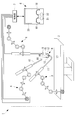
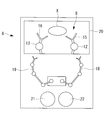
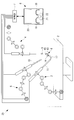
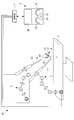
- FIG. 1 is an overall configuration diagram showing a medical system according to an embodiment of the present invention. It is a figure which shows the operation part and monitor display example in the bird's-eye view mode in the medical system of FIG. It is a figure which shows the operation part and monitor example in local mode in the medical system of FIG. It is a whole block diagram which shows the 1st modification of the medical system of FIG. It is a figure which shows the operation part and monitor display example in the bird's-eye view mode in the medical system of FIG. It is a figure which shows the operation part and monitor example in local mode in the medical system of FIG. It is a whole block diagram which shows the 2nd modification of the medical system of FIG. It is a whole block diagram which shows the 3rd modification of the medical system of FIG.
- the medical system 1 includes three robots 3, 4, and 5 installed in the vicinity of a bed 2 that lies on a patient, an operation unit 6 that is operated by an operator, And a control unit 7 for controlling the three robots 3, 4, and 5 based on an operation command input by operating the operation unit 6.
- the first robot 3 is a six-axis articulated first robot arm with a treatment unit 8 attached to the tip.
- the second robot 4 is a 6-axis multi-joint second robot arm with a second treatment section 9 attached to the tip.
- the third robot 5 is a 6-axis multi-joint third robot arm having an endoscope 10 as a second imaging unit attached to the tip.
- the treatment unit 8 includes, for example, an insertion portion 11 that penetrates the body surface tissue and is inserted into the body, and one or more joints that protrude forward from the distal end of the insertion portion 11.
- a first manipulator 12 and a second manipulator 13, and a first imaging unit 14 projecting forward from the distal end of the insertion unit 11 are provided.
- the first manipulator 12 includes a first treatment section 15 at the tip.
- the second manipulator 13 includes a third treatment section 16 at the tip.
- the insertion portion 11 is provided with a bending portion 17 at its distal end, and the postures of the first manipulator 12, the second manipulator 13, and the first imaging portion 14 can be changed also by the operation of the bending portion 17. Yes.
- the first imaging unit 14 has a local visual field range including the movable range of the first manipulator 12 and the second manipulator 13. That is, the first manipulator 12 and the second manipulator 13 arranged at the distal end of the insertion portion 11 of the treatment unit 8 are always reflected in the image of the narrow local visual field range imaged by the first imaging unit 14. A precise treatment can be performed on an affected part photographed at a large magnification.
- the endoscope 10 has a broader visual field range than the first imaging unit 14. Accordingly, the movable range of the first treatment unit 15 and the third treatment unit 16 supported by the first manipulator 12 and the second manipulator 13 by the first robot arm 3 and the tip of the second robot arm 4 are supported. Observation is possible over a relatively wide range including the movable range of the second treatment section 9.
- the third robot 5 does not operate after the global visual field range of the endoscope 10 is determined by the initial setting.
- the operation unit 6 includes a first operation input unit 18 operated by the operator's right hand and a second operation input unit 19 operated by the operator's left hand.
- Each of the operation input units 18 and 19 has a multi-joint structure, and can arbitrarily designate the positions and postures of the treatment units 9, 15, and 16 disposed at the distal end in a three-dimensional manner. Yes.
- the operation unit 6 includes a monitor (display unit) 20 that displays an image acquired by the first imaging unit 14 or the endoscope 10.
- the operation unit 6 includes a clutch 21 that switches between interlocking and disconnection of each robot arm 3, 4, 5 and the first and second operation input units 18, 19, and an image displayed on the monitor 20.
- a change-over switch (switching unit) 22 for switching between the video from the endoscope 10 and the video from the endoscope 10.
- control unit 7 When the control unit 7 is switched to display the video acquired by the first imaging unit 14 on the monitor 20 by the operation of the changeover switch 22, the control unit 7 performs image processing on the video acquired by the first imaging unit 14.
- the coordinate system fixed to the first imaging unit 14 and the coordinate system of the operation unit 6 are controlled to coincide with each other (local mode).
- control unit 7 uses the first manipulator 12 and the second manipulator 13 reflected in the image of the local visual field range acquired by the first imaging unit 14 as an operation command input in the operation unit 6. It is designed to operate accordingly.
- the control unit 7 converts the motion vector in the coordinate system of the operation unit 6 into a motion vector in the coordinate system that can realize proper hand-eye coordination for the first imaging unit 14 using, for example, a predetermined simultaneous conversion matrix.
- the coordinates are converted.
- the control unit 7 moves the first manipulator 12 in the video displayed on the monitor 20 based on the operation command input by the first operation input unit 18 of the operation unit 6 in the same direction as the first operation input unit 18. It is designed to be controlled to operate.
- the control unit 7 moves the second manipulator 13 in the image displayed on the monitor 20 based on the operation command input by the second operation input unit 19 of the operation unit 6 in the same direction as the second operation input unit 19. It is designed to be controlled to operate.
- control unit 7 When the control unit 7 is switched to display the video acquired by the endoscope 10 on the monitor 20 by the operation of the changeover switch 22, the control unit 7 performs image processing on the video acquired by the endoscope 10 and monitors the video.
- the coordinate system fixed to the endoscope 10 and the coordinate system of the operation unit 6 are controlled to coincide with each other (overhead mode).
- the control unit 7 uses the first manipulator 12 and the second treatment unit 9 that are reflected in the video of the general visual field range acquired by the endoscope 10 as an operation command input in the operation unit 6. It is designed to operate accordingly. That is, the control unit 7 converts the motion vector in the coordinate system of the operation unit 6 into, for example, a motion vector in the coordinate system capable of realizing proper hand-eye coordination with respect to the endoscope 10, thereby Based on the operation command input by the first operation input unit 18, the first robot arm 3, the bending portion of the operation unit 6, and the first manipulator (set 6 joint degrees of freedom that are redundant in total) 12 are operated. Thus, the second robot arm 4 is controlled to operate based on the operation command input by the second operation input unit 19.
- a trocar is installed in three holes penetratingly formed in the abdominal wall, and each treatment unit is penetrated through 8. Ends of the endoscope 10 and the second treatment section 9 are placed in the abdominal cavity. The operations of the three robot arms 3, 4, and 5 are restricted so as to operate with the position of the trocar as a fulcrum.
- the endoscope 10 inserted into the abdominal cavity is placed in an appropriate position with the clutch 21 disengaged.
- the third robot arm 5 is brought into a stopped state.
- the first robot arm 3, the second robot arm 4, and the bending portion 17 of the insertion portion 11 are actuated so that the first manipulator 12, the second manipulator 13, the first imaging unit 14, and the second treatment unit 9 are endoscopes. Place within 10 fields of view.
- the overhead switch mode is selected by the changeover switch 22, and the video displayed on the monitor 20 is switched to the video of the global visual field range acquired by the endoscope 10.
- the control unit 7 causes the first robot arm 3, the insertion unit 11, and the first manipulator 12 to interlock with the first treatment unit 15 by the operation input generated thereby. Move.
- the second treatment section 9 supported by another second robot arm 4 can be operated by a second operation input section 19 that operates with the left hand.
- the control unit 7 moves the second treatment unit 9 by operating the second robot arm 4 by the operation input generated thereby.
- the operation target by the first operation input unit 18 is fixed to the first manipulator 12 and the treatment unit 15, but when the mode is switched by the changeover switch 22, the second operation input unit The operation target by 19 is switched to the second treatment section 9 or the second manipulator 13 and the treatment section 16.
- the global visual field range acquired by the endoscope 10 is a wide visual field range including the movable range of the distal ends of the second treatment unit 9 and the treatment unit 8, the periphery of the distal ends of the second treatment unit 9 and the treatment unit 8
- the tissue X and the like arranged in the can also be displayed on the monitor 20 at the same time. Therefore, the operator can obtain sufficient information for avoiding interference between the second treatment unit 9 and the treatment unit 8 and surrounding tissues, and can easily perform a large surgical deployment, There is an advantage that operations such as securing can be performed quickly.
- the operator selects the local mode with the changeover switch 22 and converts the image displayed on the monitor 20 to the image from the first imaging unit 14. Switch. Thereby, the control part 7 is switched to the control mode which operates the 1st manipulator 12 and the 2nd manipulator 13 according to the operation command to the operation part 6, and the 2nd robot arm 4 is locked on the spot.
- the operator disconnects the clutch 21 and moves the first operation input unit 18 of the right hand so as to match the shape of the first manipulator 12 displayed on the monitor 20 as shown in FIG.
- the second operation input unit 19 is moved to match the shape of the second manipulator 13 displayed on the monitor 20.
- the control unit 7 operates the first manipulator 12 based on the operation command input by the first operation input unit 18 and is input by the second operation input unit 19.
- the second manipulator 13 is controlled to operate.
- the first robot arm 3 and the bending portion 17 of the insertion portion 11 are locked so as not to operate.
- control unit 7 acquires a coordinate system fixed to the first imaging unit 14 and performs control by making it coincide with the coordinate system of the operation unit 6.
- the first manipulator 12 and the second manipulator 13 are moved by an operation amount proportional to the operation amount in a direction coinciding with the operation direction of the first operation input unit 18 and the second operation input unit 19. Can be done intuitively.
- the angle of view of the image of the first imaging unit 14 is fixed by the operation of the first robot arm 3 and the bending unit 17 being locked, only the two-armed manipulators 12 and 13 are movable. . That is, the hand eye coordination is completed, and the operations of the first treatment unit 15 and the third treatment unit 16 can be performed in a concentrated manner.
- the first robot arm 3 that supports the treatment unit 8 including the insertion unit 11, the two manipulators 12 and 13, and the first imaging unit 14, the second treatment unit 9, and the second treatment unit 9 are provided.
- the case where it has the 2nd robot arm 4 to support was illustrated, instead of this, as shown in Drawing 4-Drawing 6, treatment provided with insertion part 11, single manipulator 12, and the 1st image pick-up part 14 You may apply when it has only the 1st robot arm 3 which supports the unit 23.
- the operation input unit 24 of the operation unit 6 may be single. That is, in this case, when switching to the global visual field range by the endoscope 10, the first robot arm 3 is operated by the operation input unit 24 and switched to the local visual field range by the first imaging unit 14, The manipulator 12 may be operated by the operation input unit 24.
- a medical system 25 similar to that in FIG. 1 that does not include only the second manipulator 13 may be employed.
- the overhead mode may be treatment with two arms of the first robot arm 3 and the second robot arm 4, and the local mode may be performed with one arm of only one manipulator 12.
- a medical system 26 similar to that in FIG. 1 that does not have only the second robot arm 4 may be adopted.
- the overhead view mode may be performed with one arm of only the first robot arm 3, and the local mode may be performed with the two arms of the first manipulator 12 and the second manipulator 13.
- the first manipulator 12 and the second manipulator 13 are not operated, and only the bending portion 17 and the joint of the first robot arm 3 are operated. Thereby, the hand eye coordination can be finely adjusted without switching the image and the coordinate system.
- Second treatment unit 10 Endoscope (second imaging unit) DESCRIPTION OF SYMBOLS 12 1st manipulator 13 2nd manipulator 14 1st imaging part 15 1st treatment part 16 3rd treatment part 18 1st operation input part 19 2nd operation input part 20 Monitor (display part) 21 Clutch 22 changeover switch (switching part)
Landscapes
- Engineering & Computer Science (AREA)
- Health & Medical Sciences (AREA)
- Surgery (AREA)
- Life Sciences & Earth Sciences (AREA)
- Robotics (AREA)
- Nuclear Medicine, Radiotherapy & Molecular Imaging (AREA)
- Molecular Biology (AREA)
- Veterinary Medicine (AREA)
- Public Health (AREA)
- Biomedical Technology (AREA)
- Heart & Thoracic Surgery (AREA)
- Medical Informatics (AREA)
- General Health & Medical Sciences (AREA)
- Animal Behavior & Ethology (AREA)
- Mechanical Engineering (AREA)
- Pathology (AREA)
- Oral & Maxillofacial Surgery (AREA)
- Manipulator (AREA)
- Endoscopes (AREA)
Abstract
La présente invention concerne un système médical qui est adapté à la fois à des traitements locaux et à de grands mouvements chirurgicaux et qui réduit la durée d'opération. Ce système médical (1) est pourvu : d'un premier bras robotisé (3) comprenant un premier manipulateur (12) ayant une première section de traitement (15) et une première unité d'imagerie (14) ayant un champ de vision englobant la plage mobile de la première section de traitement (15) ; d'une seconde unité d'imagerie (10) ayant un champ de vision plus large que le premier champ de vision ; d'une unité d'affichage (20) pour afficher une vidéo à partir de la première ou de la seconde unité d'imagerie (10, 14) ; d'une unité de commutation (22) pour commuter la vidéo ; d'une unité d'opération (6) pour entrer une commande d'opération pour le premier manipulateur (12) et le premier bras robotisé (3) ; et d'une unité de commande (7) pour commander le premier manipulateur (12) et le premier bras robotisé (3) en se basant sur la commande d'opération. Lorsque la vidéo est commutée pour que, à partir de la seconde unité d'imagerie (10), l'unité de commande (7) commande le premier bras robotisé (3) et le premier manipulateur (12) en se basant sur la commande d'opération. Lorsque la vidéo est commutée pour que, à partir de la première unité d'imagerie (14), l'unité de commande (7) commande le premier manipulateur (12) en se basant sur la commande d'opération.
Priority Applications (4)
| Application Number | Priority Date | Filing Date | Title |
|---|---|---|---|
| EP16811333.0A EP3311768A4 (fr) | 2015-06-18 | 2016-04-28 | Système médical |
| JP2017524714A JP6289755B2 (ja) | 2015-06-18 | 2016-04-28 | 医療システム |
| CN201680035162.6A CN107708598A (zh) | 2015-06-18 | 2016-04-28 | 医疗系统 |
| US15/838,967 US20180098817A1 (en) | 2015-06-18 | 2017-12-12 | Medical system |
Applications Claiming Priority (2)
| Application Number | Priority Date | Filing Date | Title |
|---|---|---|---|
| JP2015122943 | 2015-06-18 | ||
| JP2015-122943 | 2015-06-18 |
Related Child Applications (1)
| Application Number | Title | Priority Date | Filing Date |
|---|---|---|---|
| US15/838,967 Continuation US20180098817A1 (en) | 2015-06-18 | 2017-12-12 | Medical system |
Publications (1)
| Publication Number | Publication Date |
|---|---|
| WO2016203858A1 true WO2016203858A1 (fr) | 2016-12-22 |
Family
ID=57545535
Family Applications (1)
| Application Number | Title | Priority Date | Filing Date |
|---|---|---|---|
| PCT/JP2016/063460 Ceased WO2016203858A1 (fr) | 2015-06-18 | 2016-04-28 | Système médical |
Country Status (5)
| Country | Link |
|---|---|
| US (1) | US20180098817A1 (fr) |
| EP (1) | EP3311768A4 (fr) |
| JP (1) | JP6289755B2 (fr) |
| CN (1) | CN107708598A (fr) |
| WO (1) | WO2016203858A1 (fr) |
Cited By (5)
| Publication number | Priority date | Publication date | Assignee | Title |
|---|---|---|---|---|
| WO2020158232A1 (fr) * | 2019-01-29 | 2020-08-06 | リバーフィールド株式会社 | Dispositif d'aide à la chirurgie |
| US11399910B2 (en) | 2018-02-19 | 2022-08-02 | Olympus Corporation | Medical system |
| JP2023533922A (ja) * | 2020-07-01 | 2023-08-07 | 北京術鋭機器人股▲ふん▼有限公司 | 主従運動の制御方法、ロボットシステム、設備および記憶媒体 |
| WO2023234280A1 (fr) * | 2022-05-30 | 2023-12-07 | 川崎重工業株式会社 | Système de robot et procédé de commande d'un système de robot |
| WO2025197646A1 (fr) * | 2024-03-22 | 2025-09-25 | 本田技研工業株式会社 | Système de commande de fonctionnement à distance de robot, dispositif de commande de fonctionnement à distance de robot, procédé de commande de fonctionnement à distance de robot, et programme |
Families Citing this family (25)
| Publication number | Priority date | Publication date | Assignee | Title |
|---|---|---|---|---|
| WO2016164824A1 (fr) | 2015-04-09 | 2016-10-13 | Auris Surgical Robotics, Inc. | Système chirurgical doté de bras mécaniques configurables montés sur rail |
| KR102264368B1 (ko) | 2018-01-17 | 2021-06-17 | 아우리스 헬스, 인코포레이티드 | 조절가능 아암 지지부를 갖는 수술 플랫폼 |
| WO2020005370A1 (fr) * | 2018-06-27 | 2020-01-02 | Auris Health, Inc. | Systèmes et techniques pour fournir de multiples perspectives pendant des actes médicaux |
| US11197728B2 (en) | 2018-09-17 | 2021-12-14 | Auris Health, Inc. | Systems and methods for concomitant medical procedures |
| JP7536752B2 (ja) | 2018-09-28 | 2024-08-20 | オーリス ヘルス インコーポレイテッド | 内視鏡支援経皮的医療処置のためのシステム及び方法 |
| EP3866718A4 (fr) | 2018-12-20 | 2022-07-20 | Auris Health, Inc. | Systèmes et procédés d'alignement et d'amarrage de bras robotisé |
| CN109567732B (zh) * | 2019-02-01 | 2024-07-02 | 福建骏格科技有限公司 | 胸腹腔镜的多角度影像系统 |
| EP3890644A4 (fr) | 2019-02-08 | 2022-11-16 | Auris Health, Inc. | Manipulation et retrait de caillot à commande robotisée |
| KR102935983B1 (ko) | 2019-04-08 | 2026-03-10 | 아우리스 헬스, 인코포레이티드 | 동시 절차를 위한 시스템, 방법, 및 작업흐름 |
| EP3989841A4 (fr) | 2019-06-26 | 2023-09-20 | Auris Health, Inc. | Systèmes et procédés d'alignement et d'amarrage de bras robotisé |
| EP4007678B1 (fr) | 2019-08-02 | 2026-03-04 | Auris Health, Inc. | Systèmes et procédés de réglage de distances centrales éloignées au cours d'interventions médicales |
| US11234780B2 (en) | 2019-09-10 | 2022-02-01 | Auris Health, Inc. | Systems and methods for kinematic optimization with shared robotic degrees-of-freedom |
| EP4034350A1 (fr) | 2019-09-26 | 2022-08-03 | Auris Health, Inc. | Systèmes et procédés d'évitement de collision mettant en ?uvre des modèles d'objet |
| EP4034349A1 (fr) | 2019-09-26 | 2022-08-03 | Auris Health, Inc. | Systèmes et procédés de détection et d'évitement de collision |
| KR20220123273A (ko) | 2019-12-31 | 2022-09-06 | 아우리스 헬스, 인코포레이티드 | 해부학적 특징부 식별 및 표적설정 |
| CN114929148B (zh) | 2019-12-31 | 2024-05-10 | 奥瑞斯健康公司 | 用于经皮进入的对准界面 |
| EP4084720A4 (fr) | 2019-12-31 | 2024-01-17 | Auris Health, Inc. | Techniques d'alignement pour un accès percutané |
| WO2021198801A1 (fr) | 2020-03-30 | 2021-10-07 | Auris Health, Inc. | Optimisation d'espace de travail pour chirurgie robotique |
| US11737663B2 (en) | 2020-03-30 | 2023-08-29 | Auris Health, Inc. | Target anatomical feature localization |
| WO2022003485A1 (fr) | 2020-06-29 | 2022-01-06 | Auris Health, Inc. | Systèmes et procédés de détection de contact entre une liaison et un objet externe |
| WO2022003493A1 (fr) | 2020-06-30 | 2022-01-06 | Auris Health, Inc. | Système médical robotique avec indicateurs de proximité de collision |
| US11357586B2 (en) | 2020-06-30 | 2022-06-14 | Auris Health, Inc. | Systems and methods for saturated robotic movement |
| JP7566601B2 (ja) * | 2020-12-03 | 2024-10-15 | 株式会社メディカロイド | ロボット手術システムおよび表示方法 |
| CN115120353B (zh) * | 2020-12-15 | 2025-08-12 | 深圳市精锋医疗科技股份有限公司 | 手术机器人、计算机可读存储介质及控制装置 |
| TWI782709B (zh) * | 2021-09-16 | 2022-11-01 | 財團法人金屬工業研究發展中心 | 手術機械臂控制系統以及手術機械臂控制方法 |
Citations (5)
| Publication number | Priority date | Publication date | Assignee | Title |
|---|---|---|---|---|
| US20070216332A1 (en) * | 2003-10-20 | 2007-09-20 | Georg Lambert | Method for Effecting the Movement of a Handling Device and Image Processing Device |
| JP2008036318A (ja) * | 2006-08-10 | 2008-02-21 | Fujinon Corp | 内視鏡診断システム |
| JP2009269110A (ja) * | 2008-05-02 | 2009-11-19 | Olympus Corp | 組立装置 |
| JP2013034836A (ja) * | 2011-08-04 | 2013-02-21 | Olympus Corp | 手術支援装置 |
| JP2014079824A (ja) * | 2012-10-15 | 2014-05-08 | Toshiba Corp | 作業画面表示方法および作業画面表示装置 |
Family Cites Families (18)
| Publication number | Priority date | Publication date | Assignee | Title |
|---|---|---|---|---|
| US5339799A (en) * | 1991-04-23 | 1994-08-23 | Olympus Optical Co., Ltd. | Medical system for reproducing a state of contact of the treatment section in the operation unit |
| CA2078295C (fr) * | 1991-08-05 | 1995-11-21 | John Michael Putman | Stabiliseur d'endoscope |
| US5876325A (en) * | 1993-11-02 | 1999-03-02 | Olympus Optical Co., Ltd. | Surgical manipulation system |
| JP2000042960A (ja) * | 1998-07-29 | 2000-02-15 | Gifu Prefecture | マニピュレータの遠隔操作装置 |
| US8600551B2 (en) * | 1998-11-20 | 2013-12-03 | Intuitive Surgical Operations, Inc. | Medical robotic system with operatively couplable simulator unit for surgeon training |
| US6659939B2 (en) * | 1998-11-20 | 2003-12-09 | Intuitive Surgical, Inc. | Cooperative minimally invasive telesurgical system |
| US6459926B1 (en) * | 1998-11-20 | 2002-10-01 | Intuitive Surgical, Inc. | Repositioning and reorientation of master/slave relationship in minimally invasive telesurgery |
| US6522906B1 (en) * | 1998-12-08 | 2003-02-18 | Intuitive Surgical, Inc. | Devices and methods for presenting and regulating auxiliary information on an image display of a telesurgical system to assist an operator in performing a surgical procedure |
| US6224542B1 (en) * | 1999-01-04 | 2001-05-01 | Stryker Corporation | Endoscopic camera system with non-mechanical zoom |
| JP4460857B2 (ja) * | 2003-06-23 | 2010-05-12 | オリンパス株式会社 | 外科手術用システム |
| WO2006119495A2 (fr) * | 2005-05-03 | 2006-11-09 | Hansen Medical, Inc. | Systeme de catheter robotique |
| US20080064927A1 (en) * | 2006-06-13 | 2008-03-13 | Intuitive Surgical, Inc. | Minimally invasrive surgery guide tube |
| US8620473B2 (en) * | 2007-06-13 | 2013-12-31 | Intuitive Surgical Operations, Inc. | Medical robotic system with coupled control modes |
| US8808164B2 (en) * | 2008-03-28 | 2014-08-19 | Intuitive Surgical Operations, Inc. | Controlling a robotic surgical tool with a display monitor |
| US8864652B2 (en) * | 2008-06-27 | 2014-10-21 | Intuitive Surgical Operations, Inc. | Medical robotic system providing computer generated auxiliary views of a camera instrument for controlling the positioning and orienting of its tip |
| JP4862105B2 (ja) * | 2009-12-10 | 2012-01-25 | オリンパスメディカルシステムズ株式会社 | 医療用マニピュレータ |
| JP5800609B2 (ja) * | 2011-07-07 | 2015-10-28 | オリンパス株式会社 | 医療用マスタスレーブマニピュレータ |
| EP2729084A4 (fr) * | 2011-07-07 | 2015-03-04 | Olympus Corp | Manipulateur maître-esclave médical |
-
2016
- 2016-04-28 WO PCT/JP2016/063460 patent/WO2016203858A1/fr not_active Ceased
- 2016-04-28 CN CN201680035162.6A patent/CN107708598A/zh active Pending
- 2016-04-28 JP JP2017524714A patent/JP6289755B2/ja active Active
- 2016-04-28 EP EP16811333.0A patent/EP3311768A4/fr not_active Withdrawn
-
2017
- 2017-12-12 US US15/838,967 patent/US20180098817A1/en not_active Abandoned
Patent Citations (5)
| Publication number | Priority date | Publication date | Assignee | Title |
|---|---|---|---|---|
| US20070216332A1 (en) * | 2003-10-20 | 2007-09-20 | Georg Lambert | Method for Effecting the Movement of a Handling Device and Image Processing Device |
| JP2008036318A (ja) * | 2006-08-10 | 2008-02-21 | Fujinon Corp | 内視鏡診断システム |
| JP2009269110A (ja) * | 2008-05-02 | 2009-11-19 | Olympus Corp | 組立装置 |
| JP2013034836A (ja) * | 2011-08-04 | 2013-02-21 | Olympus Corp | 手術支援装置 |
| JP2014079824A (ja) * | 2012-10-15 | 2014-05-08 | Toshiba Corp | 作業画面表示方法および作業画面表示装置 |
Non-Patent Citations (1)
| Title |
|---|
| See also references of EP3311768A4 * |
Cited By (12)
| Publication number | Priority date | Publication date | Assignee | Title |
|---|---|---|---|---|
| US11399910B2 (en) | 2018-02-19 | 2022-08-02 | Olympus Corporation | Medical system |
| WO2020158232A1 (fr) * | 2019-01-29 | 2020-08-06 | リバーフィールド株式会社 | Dispositif d'aide à la chirurgie |
| JP2020120764A (ja) * | 2019-01-29 | 2020-08-13 | リバーフィールド株式会社 | 手術支援装置 |
| CN113474129A (zh) * | 2019-01-29 | 2021-10-01 | 瑞德医疗机器股份有限公司 | 手术辅助装置 |
| EP3919235A4 (fr) * | 2019-01-29 | 2022-11-09 | RIVERFIELD Inc | Dispositif d'aide à la chirurgie |
| CN113474129B (zh) * | 2019-01-29 | 2024-03-26 | 瑞德医疗机器股份有限公司 | 手术辅助装置 |
| US12167942B2 (en) | 2019-01-29 | 2024-12-17 | Riverfield Inc. | Surgery assisting device |
| JP2023533922A (ja) * | 2020-07-01 | 2023-08-07 | 北京術鋭機器人股▲ふん▼有限公司 | 主従運動の制御方法、ロボットシステム、設備および記憶媒体 |
| JP7589263B2 (ja) | 2020-07-01 | 2024-11-25 | 北京術鋭機器人股▲ふん▼有限公司 | 主従運動の制御方法、ロボットシステム、設備および記憶媒体 |
| US12502236B2 (en) | 2020-07-01 | 2025-12-23 | Beijing Surgerii Robotics Company Limited | Master-slave motion control method, robot system, device, and storage medium |
| WO2023234280A1 (fr) * | 2022-05-30 | 2023-12-07 | 川崎重工業株式会社 | Système de robot et procédé de commande d'un système de robot |
| WO2025197646A1 (fr) * | 2024-03-22 | 2025-09-25 | 本田技研工業株式会社 | Système de commande de fonctionnement à distance de robot, dispositif de commande de fonctionnement à distance de robot, procédé de commande de fonctionnement à distance de robot, et programme |
Also Published As
| Publication number | Publication date |
|---|---|
| US20180098817A1 (en) | 2018-04-12 |
| CN107708598A (zh) | 2018-02-16 |
| JPWO2016203858A1 (ja) | 2017-09-07 |
| EP3311768A4 (fr) | 2019-02-27 |
| JP6289755B2 (ja) | 2018-03-07 |
| EP3311768A1 (fr) | 2018-04-25 |
Similar Documents
| Publication | Publication Date | Title |
|---|---|---|
| JP6289755B2 (ja) | 医療システム | |
| JP7257559B2 (ja) | コンピュータ支援遠隔操作システムにおける補助器具制御 | |
| US11941734B2 (en) | Rendering tool information as graphic overlays on displayed images of tools | |
| US20220249193A1 (en) | Systems and methods for presenting augmented reality in a display of a teleoperational system | |
| US20250152283A1 (en) | Systems and methods for master/tool registration and control for intuitive motion | |
| US20240108425A1 (en) | Systems and methods for onscreen menus in a teleoperational medical system | |
| US8892224B2 (en) | Method for graphically providing continuous change of state directions to a user of a medical robotic system | |
| JP5908172B2 (ja) | 手術支援システムおよび手術支援システムの制御方法 | |
| CN115500950B (zh) | 内窥镜位姿调整方法、手术机器人及存储介质 | |
| KR20230029999A (ko) | 원격조작 의료 시스템에서 기구의 스크린상 식별정보를 렌더링하기 위한 시스템 및 방법 | |
| KR20230003408A (ko) | 원격조작 의료 시스템에서 기구의 스크린상 식별을 위한 시스템 및 방법 | |
| CN110461205A (zh) | 手术成像系统、手术用图像处理设备以及用于控制成像过程的方法 | |
| US20160007835A1 (en) | Master-slave system and driving method therefor | |
| JP5800610B2 (ja) | 医療用マスタスレーブマニピュレータ | |
| US12266040B2 (en) | Rendering tool information as graphic overlays on displayed images of tools | |
| US20240390068A1 (en) | Systems and methods for generating workspace geometry for an instrument |
Legal Events
| Date | Code | Title | Description |
|---|---|---|---|
| 121 | Ep: the epo has been informed by wipo that ep was designated in this application |
Ref document number: 16811333 Country of ref document: EP Kind code of ref document: A1 |
|
| ENP | Entry into the national phase |
Ref document number: 2017524714 Country of ref document: JP Kind code of ref document: A |
|
| NENP | Non-entry into the national phase |
Ref country code: DE |
|
| WWE | Wipo information: entry into national phase |
Ref document number: 2016811333 Country of ref document: EP |