WO2016203979A1 - Dispositif de génération d'énergie électrique à stockage d'énergie par air comprimé - Google Patents
Dispositif de génération d'énergie électrique à stockage d'énergie par air comprimé Download PDFInfo
- Publication number
- WO2016203979A1 WO2016203979A1 PCT/JP2016/066486 JP2016066486W WO2016203979A1 WO 2016203979 A1 WO2016203979 A1 WO 2016203979A1 JP 2016066486 W JP2016066486 W JP 2016066486W WO 2016203979 A1 WO2016203979 A1 WO 2016203979A1
- Authority
- WO
- WIPO (PCT)
- Prior art keywords
- heat medium
- temperature
- expansion
- side heat
- compression
- Prior art date
- Legal status (The legal status is an assumption and is not a legal conclusion. Google has not performed a legal analysis and makes no representation as to the accuracy of the status listed.)
- Ceased
Links
Images



Classifications
-
- F—MECHANICAL ENGINEERING; LIGHTING; HEATING; WEAPONS; BLASTING
- F01—MACHINES OR ENGINES IN GENERAL; ENGINE PLANTS IN GENERAL; STEAM ENGINES
- F01D—NON-POSITIVE DISPLACEMENT MACHINES OR ENGINES, e.g. STEAM TURBINES
- F01D17/00—Regulating or controlling by varying flow
- F01D17/02—Arrangement of sensing elements
- F01D17/08—Arrangement of sensing elements responsive to condition of working-fluid, e.g. pressure
-
- F—MECHANICAL ENGINEERING; LIGHTING; HEATING; WEAPONS; BLASTING
- F01—MACHINES OR ENGINES IN GENERAL; ENGINE PLANTS IN GENERAL; STEAM ENGINES
- F01D—NON-POSITIVE DISPLACEMENT MACHINES OR ENGINES, e.g. STEAM TURBINES
- F01D17/00—Regulating or controlling by varying flow
- F01D17/20—Devices dealing with sensing elements or final actuators or transmitting means between them, e.g. power-assisted
-
- F—MECHANICAL ENGINEERING; LIGHTING; HEATING; WEAPONS; BLASTING
- F01—MACHINES OR ENGINES IN GENERAL; ENGINE PLANTS IN GENERAL; STEAM ENGINES
- F01D—NON-POSITIVE DISPLACEMENT MACHINES OR ENGINES, e.g. STEAM TURBINES
- F01D19/00—Starting of machines or engines; Regulating, controlling, or safety means in connection therewith
-
- F—MECHANICAL ENGINEERING; LIGHTING; HEATING; WEAPONS; BLASTING
- F01—MACHINES OR ENGINES IN GENERAL; ENGINE PLANTS IN GENERAL; STEAM ENGINES
- F01D—NON-POSITIVE DISPLACEMENT MACHINES OR ENGINES, e.g. STEAM TURBINES
- F01D21/00—Shutting-down of machines or engines, e.g. in emergency; Regulating, controlling, or safety means not otherwise provided for
-
- F—MECHANICAL ENGINEERING; LIGHTING; HEATING; WEAPONS; BLASTING
- F02—COMBUSTION ENGINES; HOT-GAS OR COMBUSTION-PRODUCT ENGINE PLANTS
- F02C—GAS-TURBINE PLANTS; AIR INTAKES FOR JET-PROPULSION PLANTS; CONTROLLING FUEL SUPPLY IN AIR-BREATHING JET-PROPULSION PLANTS
- F02C6/00—Plural gas-turbine plants; Combinations of gas-turbine plants with other apparatus; Adaptations of gas-turbine plants for special use
-
- F—MECHANICAL ENGINEERING; LIGHTING; HEATING; WEAPONS; BLASTING
- F02—COMBUSTION ENGINES; HOT-GAS OR COMBUSTION-PRODUCT ENGINE PLANTS
- F02C—GAS-TURBINE PLANTS; AIR INTAKES FOR JET-PROPULSION PLANTS; CONTROLLING FUEL SUPPLY IN AIR-BREATHING JET-PROPULSION PLANTS
- F02C6/00—Plural gas-turbine plants; Combinations of gas-turbine plants with other apparatus; Adaptations of gas-turbine plants for special use
- F02C6/14—Gas-turbine plants having means for storing energy, e.g. for meeting peak loads
- F02C6/16—Gas-turbine plants having means for storing energy, e.g. for meeting peak loads for storing compressed air
-
- F—MECHANICAL ENGINEERING; LIGHTING; HEATING; WEAPONS; BLASTING
- F02—COMBUSTION ENGINES; HOT-GAS OR COMBUSTION-PRODUCT ENGINE PLANTS
- F02C—GAS-TURBINE PLANTS; AIR INTAKES FOR JET-PROPULSION PLANTS; CONTROLLING FUEL SUPPLY IN AIR-BREATHING JET-PROPULSION PLANTS
- F02C9/00—Controlling gas-turbine plants; Controlling fuel supply in air- breathing jet-propulsion plants
- F02C9/16—Control of working fluid flow
-
- Y—GENERAL TAGGING OF NEW TECHNOLOGICAL DEVELOPMENTS; GENERAL TAGGING OF CROSS-SECTIONAL TECHNOLOGIES SPANNING OVER SEVERAL SECTIONS OF THE IPC; TECHNICAL SUBJECTS COVERED BY FORMER USPC CROSS-REFERENCE ART COLLECTIONS [XRACs] AND DIGESTS
- Y02—TECHNOLOGIES OR APPLICATIONS FOR MITIGATION OR ADAPTATION AGAINST CLIMATE CHANGE
- Y02E—REDUCTION OF GREENHOUSE GAS [GHG] EMISSIONS, RELATED TO ENERGY GENERATION, TRANSMISSION OR DISTRIBUTION
- Y02E60/00—Enabling technologies; Technologies with a potential or indirect contribution to GHG emissions mitigation
- Y02E60/16—Mechanical energy storage, e.g. flywheels or pressurised fluids
Definitions
- the present invention relates to a compressed air storage power generator.
- CAES compressed air storage
- Conventional compressed air storage power generators store electrical energy in the accumulator tank as compressed air during off-peak hours of the power plant, operate the generator by driving the expander with compressed air during high power demand time, and Is generally generated.
- Patent Document 1 discloses such a CAES power generator.
- the CAES power generator of Patent Document 1 uses a heat exchanger to exchange heat between the heat medium and air, collects the compression heat generated by the compressor into the heat medium, Heat is returned to the air before it expands.
- the reversal of the temperature of the heat medium and air in the heat exchanger is not taken into consideration. Specifically, in the heat exchanger on the expansion side, when heat exchange is performed when the heat medium temperature is lower than the air temperature, the air temperature decreases and the expansion efficiency decreases. In the heat exchanger on the compression side, when heat exchange is performed when the heat medium temperature is higher than the air temperature, the heat medium temperature is lowered and the heat storage temperature is lowered. Furthermore, when the compressor is a multistage type, the temperature of the air supplied to the downstream compressor body increases, and the compression efficiency in the downstream compressor body also decreases. Thus, if the heat exchange is continued in a state where the temperature of the heat medium and air in the heat exchange section is reversed, the efficiency of the system is lowered.
- An object of the present invention is to provide a compressed air storage power generation device that prevents the temperature of the air supplied to the expander from decreasing due to heat exchange, and can prevent the system efficiency from decreasing.
- the present invention includes an electric motor driven by fluctuating input power, a compressor mechanically connected to the electric motor to compress air, and a compression fluidly connected to the compressor and compressed by the compressor.
- An accumulator tank for storing air; an expander fluidly connected to the accumulator tank and driven by compressed air supplied from the accumulator tank; a generator mechanically connected to the expander; and heat
- a heat medium tank for storing the medium, fluidly connected to the heat medium tank, heat exchange between the heat medium supplied from the heat medium tank and the compressed air supplied to the expander, and heating the compressed air
- An expansion-side heat exchange unit for measuring the temperature of the expansion-side heat exchanger supplied to the expansion-side heat exchange unit, and the temperature of the compressed air supplied to the expansion-side heat exchange unit.
- Expansion side air temperature sensor to measure and The temperature measured by the expansion side heat medium supply stop unit for stopping the supply of the heat medium to the expansion side heat exchange unit and the expansion side heat medium temperature sensor is higher than the temperature measured by the expansion side air temperature sensor.
- a compressed air storage power generator is provided that includes a control device that controls the expansion side heat medium supply stop unit to stop the supply of the heat medium to the expansion side heat exchange unit.
- the heat medium temperature and the air temperature are measured before the heat exchange in the expansion side heat exchange unit, and when the heat medium temperature is lower than the air temperature, the heat exchange is stopped by the expansion side heat medium supply stop unit. Therefore, it is possible to prevent the temperature of the air supplied to the expander from decreasing due to heat exchange. If heat is exchanged in the state where the heat medium temperature is lower than the air temperature in the expansion side heat exchanging section, the air temperature is lowered, and the expanded air is supplied to the expander, so that the expansion efficiency is lowered. Therefore, this is prevented and the efficiency of the system is maintained.
- the expander is a multi-stage type, and includes a plurality of expander bodies, and the expansion-side heat exchange unit is the second highest pressure stage from the expander body of the highest pressure stage among the expander bodies.
- An interheater that heats the compressed air by exchanging heat between the compressed air supplied to the expander main body and the heat medium supplied from the heat medium tank; The supply of the heat medium to the heater is stopped, the expansion side heat medium temperature sensor measures the temperature of the heat medium supplied to the inter heater, and the expansion side air temperature sensor is supplied to the inter heater. The temperature of the compressed air may be measured.
- the temperature of the air supplied to the expander main body, which is the second high-pressure stage is decreased with respect to the multistage expander.
- the rotation speed is constant, the pressure difference between the expander body at the highest pressure stage and the expander body at the second highest pressure stage is kept constant, so the air storage amount of the pressure accumulating tank is reduced.
- the differential pressure before and after the expander body at the highest pressure stage decreases. Accordingly, the work of expansion in the expander body at the highest pressure stage is reduced, the amount of expansion heat absorption is reduced, and the exhaust temperature of the expander body at the highest pressure stage is increased.
- the expansion-side heat medium supply stop unit includes a valve for stopping the supply of the heat medium to the expansion-side heat exchange unit, and an expansion-side bypass channel that flows the heat medium bypassing the expansion-side heat exchange unit And may be provided.
- the expansion-side heat medium supply stop unit can be configured with a simple configuration.
- the flow of the heat medium does not stop because the heat medium flows through the expansion side bypass flow path even when heat exchange is stopped in the expansion side heat exchange section.
- the control device is configured to stop the expansion side heat medium supply stop unit. May be controlled to stop the supply of the heat medium to the expansion side heat exchange section.
- a predetermined temperature difference is provided as a margin value, so that a temperature drop of the compressed air in the expansion side heat exchange unit can be prevented more reliably. For example, even if there is an error in the measurement of the heat medium temperature and air temperature before heat exchange at the expansion side heat exchange part, or even if there is some temperature change when air and heat medium flow through the pipe It is.
- the compressed air storage power generation apparatus is fluidly connected to the heat medium tank, exchanges heat between the air compressed by the compressor and the heat medium, and heats the heat medium, and the compression A compression side heat medium temperature sensor for measuring the temperature of the heat medium supplied to the side heat exchange unit, a compression side air temperature sensor for measuring the temperature of the compressed air supplied to the compression side heat exchange unit, and the compression side A compression-side heat medium supply stop unit for stopping supply of the heat medium to the heat exchange unit, and the controller measures the temperature measured by the compression-side heat medium temperature sensor at the compression-side air temperature sensor. When the temperature is higher than the measured temperature, it is preferable to stop the supply of the heat medium to the compression side heat exchange unit by controlling the compression side heat medium supply stop unit.
- the heat medium temperature and the air temperature are measured before the heat exchange in the compression side heat exchange unit, and when the heat medium temperature is higher than the air temperature, the heat exchange is stopped by the compression side heat medium supply stop unit. Therefore, it is possible to prevent the temperature of the heat medium stored in the heat medium tank from being lowered due to heat exchange.
- the compression side heat exchanging section when heat exchange is performed in a state where the heat medium temperature is higher than the air temperature, the heat medium temperature is lowered, and the heat medium that is lowered in temperature is supplied to the heat medium tank. System efficiency is reduced. Therefore, this is prevented and the efficiency of the system is maintained.
- the compressor is a multi-stage type, and includes a plurality of compressor main bodies, and the compression side heat exchange unit is supplied from the compressor main body of the highest pressure stage to the accumulator tank among the compressor main bodies.
- An aftercooler that cools the compressed air by exchanging heat between the compressed air and the heating medium supplied from the heating medium tank, and the compression-side heating medium supply stop unit supplies the heating medium to the aftercooler.
- the compression side heat medium temperature sensor measures the temperature of the heat medium supplied to the aftercooler, and the compression side air temperature sensor measures the temperature of the compressed air supplied to the aftercooler. Also good.
- the temperature of the heat medium supplied to the heat medium tank can be prevented from decreasing. Specifically, if the number of revolutions is constant, the pressure difference between the compressor body, which is the highest pressure stage, and the compressor body, which is the second highest pressure stage, is kept constant. In this case, the differential pressure before and after the compressor body at the highest pressure stage decreases. Therefore, the amount of compression work at the highest pressure stage is reduced, the amount of heat generated by compression is reduced, and the discharge temperature of the compressor body at the highest pressure stage is lowered. Even when the lowered air temperature falls below the heat medium temperature, if the heat exchange is continued in the compression side heat exchange section, the heat medium temperature is lowered and the heat storage temperature in the heat medium tank is lowered.
- the temperature reversal between the heat medium and the air in the compression side heat exchange part is more likely to occur than in the single stage type. For this reason, it is effective to stop the heat exchange by the compression side heat medium supply stop unit when the heat medium temperature and the air temperature are measured before heat exchange in the aftercooler and the heat medium temperature is higher than the air temperature.
- the compression-side heat medium supply stop unit includes a valve for stopping the supply of the heat medium to the compression-side heat exchange unit, and a compression-side bypass channel that flows the heat medium bypassing the compression-side heat exchange unit And may be provided.
- the compression-side heat medium supply stop unit can be configured with a simple configuration.
- the flow of the heat medium does not stop because the heat medium flows through the compression side bypass flow path even when heat exchange is stopped in the compression side heat exchange section.
- the control device When the temperature measured by the compression-side heat medium temperature sensor is lower than a value obtained by subtracting a predetermined margin value from the temperature measured by the compression-side air temperature sensor, the control device, the compression-side heat medium supply stop unit May be controlled to stop the supply of the heat medium to the compression side heat exchange section.
- a predetermined temperature difference is provided as a margin value, so that the temperature decrease of the heat medium in the compression side heat exchange unit can be prevented more reliably.
- a predetermined temperature difference is provided as a margin value, so that the temperature decrease of the heat medium in the compression side heat exchange unit can be prevented more reliably.
- the heat medium temperature and the air temperature are measured before the heat exchange in the expansion side heat exchange unit, and when the heat medium temperature is lower than the air temperature, the heat exchange is stopped by the expansion side heat medium supply stop unit. Therefore, the temperature of the air supplied to the expander can be prevented from decreasing due to heat exchange. Therefore, a decrease in system efficiency can be prevented.
- the schematic structure figure of the compressed air storage power generator concerning a 1st embodiment of the present invention.
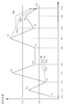
- the graph which shows an example of the temperature change from the upstream to the downstream in the air flow path of the compressed air storage power generation device of FIG.
- the flowchart which shows the switching control of the compression side bypass flow path in consideration of the margin value.
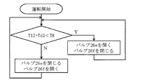
- the flowchart which shows switching control of the expansion side bypass flow path in consideration of the margin value.
- the schematic block diagram of the compressed air storage power generation apparatus which concerns on 2nd Embodiment of this invention.
- FIG. 1 shows a schematic configuration diagram of a compressed air energy storage (CAES) power generator 2 according to a first embodiment of the present invention.
- the CAES power generation device 2 equalizes output fluctuations to a power system (not shown) that is a demand destination when generating power using renewable energy in a power generation facility (not shown), Outputs power that matches the fluctuation.
- the CAES power generator 2 includes an air flow path and a heat medium flow path.
- the air flow path is mainly provided with a compressor 4, a pressure accumulating tank 6, and an expander 8, which are fluidly connected by air pipes 10a and 10b, in which air flows. (See solid arrows).
- the heat medium flow path is mainly provided with a compression side heat exchange unit 12, a heat medium tank 14, and an expansion side heat exchange unit 16, and these are fluidly connected by heat medium pipes 18a and 18b. In the interior, a heat medium flows (see broken line arrows).
- the air flow path will be described with reference to FIG.
- the sucked air is compressed by the compressor 4, stored in the pressure accumulating tank 6, supplied to the expander 8 as necessary, and used for power generation by the generators 20a and 20b.
- the compressor 4 of this embodiment is a two-stage screw type having a low-pressure stage compressor body 4a and a high-pressure stage compressor body 4b.
- the screw-type compressor 4 By using the screw-type compressor 4, it is possible to quickly follow the fluctuating input and to quickly change the power generation output.
- the low-pressure stage compressor body 4a and the high-pressure stage compressor body 4b include motors 24a and 24b, respectively.
- the motors 24a and 24b are mechanically connected to the screws inside the low-pressure stage compressor body 4a and the high-pressure stage compressor body 4b.
- the motors 24a and 24b When input power generated by renewable energy from a power generation facility (not shown) is supplied to the motors 24a and 24b, the motors 24a and 24b are driven by this power, and the screw rotates to rotate the low-pressure stage compressor body 4a and the high-pressure unit.
- the stage compressor body 4b operates.
- the low-pressure stage compressor body 4a When operated by the motors 24a and 24b, the low-pressure stage compressor body 4a sucks air from the intake port 4c through the air pipe 10a, compresses it and discharges it from the discharge port 4d, and passes through the air pipe 10a to the high-pressure stage compressor body 4b.
- the high-pressure compressor main body 4b sucks air from the intake port 4e through the air pipe 10a, compresses it and discharges it from the discharge port 4f, and pumps the compressed air to the pressure accumulation tank 6 through the air pipe 10a.
- the compressor 4 is not limited to a two-stage type, and may be a three-stage type or more, and a plurality of compressors may be installed.
- the kind of the compressor 4 is not specifically limited, For example, a turbo type, a scroll type, a reciprocating type, etc. may be sufficient.
- the air pipe 10a extending from the compressor 4 to the accumulator tank 6 is provided with a valve 26a.
- the valve 26a can be opened and closed as necessary to allow or block the supply of compressed air to the accumulator tank 6.
- the pressure accumulating tank 6 stores the compressed air fed from the compressor 4. Therefore, energy can be stored in the pressure accumulation tank 6 as compressed air. Accumulated pressure is determined based on a balance with the required power storage capacity, installation space, and legal regulations.
- the accumulator tank 6 is fluidly connected to the expander 8 via the expansion side heat exchange unit 16 through the air pipe 10b. The compressed air stored in the pressure accumulating tank 6 is supplied to the expander 8.
- the air pipe 10b extending from the pressure accumulating tank 6 to the expander 8 is provided with a valve 26b.
- the valve 26b can be opened and closed as necessary to allow or block the supply of compressed air to the expander 8.
- the expander 8 is a two-stage screw type having a low-pressure stage expander body 8a and a high-pressure stage expander body 8b.
- the low-pressure stage expander body 8a and the high-pressure stage expander body 8b include generators 20a and 20b.
- the generators 20a and 20b are mechanically connected to the screws inside the low-pressure stage expander body 8a and the high-pressure stage expander body 8b.
- the high-pressure stage expander body 8b is fluidly connected to the pressure accumulation tank 6 through the air pipe 10b at the air supply port 8c, and is supplied with compressed air from the air supply port 8c.
- the high-pressure stage expander body 8b is operated by the supplied compressed air and drives the generator 20b.
- the high-pressure stage expander body 8b supplies compressed air from the exhaust port 8d to the air supply port 8e of the low-pressure stage expander body 8a through the air pipe 10b.
- the low-pressure stage expander main body 8a is similarly operated by the supplied compressed air, and drives the generator 20a.
- the low-pressure stage expander main body 8a exhausts the air expanded to the outside through the air pipe 10b from the exhaust port 8f.
- the electric power generated by the generators 20a and 20b is supplied to an external power system (not shown).
- the expander 8 is not limited to the two-stage type, and may be a three-stage type or more, and a plurality of units may be installed.
- the type of the expander 8 is not particularly limited, and may be, for example, a turbo type or a scroll type.
- the heat medium flow path the heat generated by the compressor 4 is recovered by the heat medium into the heat medium by the compression side heat exchange unit 12, the heat medium heated by the heat medium tank 14 is stored, and the expansion side heat exchange unit 16, the heat is returned to the compressed air before being expanded by the expander 8.
- Pumps 28a and 28b are installed in the heat medium pipes 18a and 18b constituting the heat medium flow path, and the heat medium is circulated in the respective heat medium pipes 18a and 18b by the pumps 28a and 28b.
- the type of the heat medium is not particularly limited, and for example, a mineral oil or glycol heat medium may be used.
- the compression-side heat exchange unit 12 includes an intercooler 12a and an aftercooler 12b.
- the intercooler 12a and the aftercooler 12b collect the heat generated by the compressor 4 in a heat medium. Therefore, in the intercooler 12a and the aftercooler 12b, the temperature of the compressed air decreases and the temperature of the heat medium increases.
- the intercooler 12a is provided in an air pipe 10a extending from the low pressure stage compressor body 4a to the high pressure stage compressor body 4b in the air flow path. Moreover, it is provided in the downstream of the expansion side heat exchange part 16 (interheater 12a) in the heat medium flow path. Therefore, the intercooler 12a exchanges heat between the compressed air that has been heated after being compressed by the low-pressure stage compressor body 4a and the heat medium that has been cooled by the heat exchange at the expansion side heat exchanging unit 16 (interheater 12a). The compression heat generated in the low-pressure stage compressor body 4a is recovered in the heat medium. The heating medium whose temperature has been raised here is supplied to the second heating medium tank 14b through the heating medium pipe 18b.
- the aftercooler 12b is provided in an air pipe 10a extending from the high-pressure compressor main body 4b to the accumulator tank 6 in the air flow path. Moreover, it is provided in the downstream of the expansion side heat exchange part 16 (preheater 16a) in the heat medium flow path. Therefore, the aftercooler 12b exchanges heat between the compressed air compressed by the high-pressure stage compressor body 4b and the heat medium having cooled the temperature by exchanging heat at the expansion side heat exchanging section 16 (preheater 16a). The compression heat generated in the main body 4a and the high-pressure compressor main body 4b is recovered in a heat medium. The heat medium whose temperature has been increased is supplied to the first heat medium tank 14a through the heat medium pipe 18a.
- the first heat medium tank 14a and the second heat medium tank 14b constitute the heat medium tank 14 of the present invention.
- the first heat medium tank 14a and the second heat medium tank 14b are preferably insulated so as not to release the heat of the stored heat medium to the outside.
- the heat medium tank 14 of this embodiment is provided with two tanks, the 1st heat medium tank 14a and the 2nd heat medium tank 14b, the structure of the heat medium tank 14 is not limited to this, One or three More than one tank may be provided.
- the heat medium stored in the first heat medium tank 14a and the second heat medium tank 14b is supplied to the expansion side heat exchange unit 16 (preheater 16a, interheater 16b) through the heat medium pipes 18a and 18b, respectively.
- the expansion-side heat exchange unit 16 includes a preheater 16a and an interheater 16b.
- the preheater 16a and the interheater 16b heat the compressed air supplied to the expander 8 with a heat medium. Accordingly, in the pre-heater 16a and the inter-heater 16b, the temperature of the compressed air increases and the temperature of the heat medium decreases.
- the pre-heater 16a is provided in an air pipe 10b extending from the pressure accumulation tank 6 to the high-pressure stage expander body 8b in the air flow path. Further, it is provided downstream of the first heat medium tank 14a in the heat medium flow path. Therefore, the pre-heater 16a exchanges heat between the compressed air supplied from the accumulator tank 6 to the high-pressure stage expander body 8b and the heat medium supplied from the first heat medium tank 14a, and supplies the heat to the high-pressure stage expander body 8b. The compressed air is heated. The heat medium having lowered the temperature is supplied to the compression side heat exchange unit 12 (aftercooler 12b) through the heat medium pipe 18a.
- the interheater 16b is provided in an air pipe 10b extending from the high-pressure expander body 8b to the low-pressure expander body 8a in the air flow path. Further, it is provided downstream of the second heat medium tank 14b in the heat medium flow path. Therefore, the interheater 16b exchanges heat between the air supplied to the low-pressure stage expander body 8a after expansion in the high-pressure stage compressor body 4b and the heat medium supplied from the second heat medium tank 14b, and the low-pressure stage expansion.
- the air supplied to the machine main body 8a is heated.
- the heat medium having cooled down is supplied to the compression-side heat exchange unit 12 (intercooler 12a) through the heat medium pipe 18b.
- the heat medium circulates between the compression side heat exchange unit 12, the heat medium tank 14, and the expansion side heat exchange unit 16 through the heat medium pipes 18a and 18b.
- the first heat medium tank 14a and the second heat medium tank 14b are provided separately, so that the heat medium can be stored for each temperature. Therefore, in the expansion side heat exchange section 16, the compressed air flowing into the two-stage type expander 8 can be efficiently heated with the heat medium stored at high and low temperatures, and the charge / discharge efficiency can be maintained high.
- the aftercooler 12b, the first heat medium tank 14a, and the preheater 16a are fluidly connected by the heat medium pipe 18a, and the intercooler 12a, the second heat medium tank 14b, the interheater 16b, Are fluidly connected by a heat medium pipe 18b.
- the connection configuration is not limited to this.
- the aftercooler 12b, the first heat medium tank 14a, and the interheater 16b are fluidly connected, and the intercooler 12a, the second heat medium tank 14b, The preheater 16a may be fluidly connected.
- a compression side bypass passage 30 is provided for bypassing the aftercooler 12b and flowing the heating medium.
- the compression side bypass flow path 30 is provided with a valve 26 c. Normally, the valve 26 c is closed, and no heat medium flows through the compression side bypass flow path 30.
- the heating medium pipe 18a upstream of the aftercooler 12b is provided with a valve 26d for stopping the supply of the heating medium to the aftercooler 12b. 26 c is opened, the valve 26 d is closed, the supply of the heat medium to the aftercooler 12 b is stopped, and the heat medium flows through the compression-side bypass flow path 30.
- the compression side bypass flow path 30 and the valves 26c and 26d of the present embodiment constitute a compression side heat medium supply stop unit of the present invention.
- an expansion-side bypass flow path 32 that bypasses the interheater 16b and flows the heat medium is provided.
- the expansion side bypass flow path 32 is provided with a valve 26 e. Normally, the valve 26 e is closed, and the heat medium does not flow into the expansion side bypass flow path 32.
- the heating medium pipe 18b upstream of the interheater 16b is provided with a valve 26f for stopping the supply of the heating medium to the interheater 16b. 26e is opened, the valve 26f is closed, the supply of the heat medium to the inter-heater 16b is stopped, and the heat medium flows through the expansion side bypass flow path 32.
- the expansion side bypass flow path 32 and the valves 26e and 26f of the present embodiment constitute an expansion side heat medium supply stop unit of the present invention.
- FIG. 2 is a graph showing an example of temperature change from upstream to downstream in the air flow path of the CAES power generator 2.
- the vertical axis indicates the air temperature
- the horizontal axis indicates the corresponding points P1 to P10 (see FIG. 1) of the air flow path.
- a pressure accumulation tank 6 insulated from the outside air may be used.
- the pressure in the pressure accumulating tank 6 decreases with the passage of time when the state transitions from the state after charging (after accumulating) or in the middle of charging (in the middle of accumulating) to the discharging stroke (power generation stroke).
- the accumulated pressure for storing the compressed air in the accumulator tank 6 is referred to as charging
- the generation of electricity with the generator using the compressed air in the accumulator tank is referred to as discharging.
- the intermediate pressure at the point P2 (or the point P3 having a pressure equal to the point P2) is maintained substantially constant at a constant rotational speed.
- the differential pressure before and after the high-pressure compressor body 4b that is, the difference between the pressure at the point P4 and the pressure at the point P3 decreases with time, and the discharge temperature T4 of the high-pressure compressor body 4b decreases accordingly ( The temperature decreases from the temperature T4 in FIG. 2 to the temperature T4a).
- the air inlet temperature T4 of the aftercooler 12b approaches or decreases below the heat medium inlet temperature T11 of the aftercooler 12b, the air cannot be cooled. Or conversely, the air will be heated, the temperature of air will rise and the temperature of a heat medium will fall.
- a compression-side bypass passage 30 is provided in the heat medium passage of the aftercooler 12b.
- the discharge temperature T4 of the high-pressure stage compressor body 4b is constantly monitored by the compression side air temperature sensor 34, and the heat medium inlet T11 of the aftercooler 12b is constantly monitored by the compression side heat medium temperature sensor 36.
- the opening and closing of the valves 26c and 26d is switched based on the magnitude and temperature difference of these temperatures, the supply of the heat medium to the aftercooler 12b is stopped, the heat medium is passed through the compression side bypass flow path 30, and heat exchange is performed. Is stopped.
- the differential pressure before and after the high-pressure expander main body 8b that is, the difference between the pressure at the point P7 and the pressure at the point P8 decreases with time, and the exhaust temperature T8 of the high-pressure expander main body 8b increases accordingly ( FIG. 2 shows temperature T8 to temperature T8a).
- FIG. 2 shows temperature T8 to temperature T8a.
- an expansion-side bypass flow path 32 is provided in the heat medium flow path of the interheater 16b as shown in FIG. Further, the exhaust temperature T9 of the high-pressure expander body 8b is constantly monitored by the expansion side air temperature sensor 38, and the heat medium inlet temperature T12 of the interheater 16b is constantly monitored by the expansion side heat medium temperature sensor 40. Then, the opening and closing of the valves 26e and 26f is switched based on the magnitude of the temperature and the temperature difference, the supply of the heat medium to the inter-heater 16b is stopped, the heat medium is caused to flow through the expansion side bypass flow path 32, and the heat exchange is stopped. ing.
- the CAES power generator 2 includes a control device 42.
- the control device 42 is constructed by hardware including a sequencer and the software installed therein.
- the compression side air temperature sensor 34, the compression side heat medium temperature sensor 36, the expansion side air temperature sensor 38, and the expansion side heat medium temperature sensor 40 output the detected pressure to the control device 42.
- the control device 42 controls the opening and closing of the valves 26c to 26f based on these detected temperatures.
- control device 42 controls to open the valve 26c and close the valve 26d when the temperature T4 measured by the compression-side heat medium temperature sensor 36 is lower than the temperature T11 measured by the compression-side air temperature sensor 34. Then, the heating medium is caused to flow through the compression-side bypass flow path 30, and the supply of the heating medium to the aftercooler 12b is stopped.
- the differential pressure between the high-pressure stage compressor body 4b, which is the highest pressure stage, and the low-pressure stage compressor body 4a, which is the second highest pressure stage is maintained constant, the amount of air stored in the accumulator tank 6 is reduced.
- the differential pressure before and after the high-pressure stage compressor main body 4b of the highest pressure stage decreases. Accordingly, the amount of compression work at the highest pressure stage is reduced, the amount of heat generated by compression is reduced, and the discharge temperature of the high pressure stage compressor body 4b at the highest pressure stage is lowered. Even when the lowered air temperature falls below the heat medium temperature, if the heat exchange is continued in the compression side heat exchange unit 12, the heat medium temperature is lowered, and the heat storage temperature in the heat medium tank 14 is lowered.
- the temperature reversal between the heat medium and the air in the compression side heat exchange unit 12 is more likely to occur than in the single stage type. For this reason, it is effective to stop the heat exchange as described above when the heat medium temperature and the air temperature are measured in the aftercooler 12b before the heat exchange and the heat medium temperature is higher than the air temperature.
- the compression-side bypass medium 30 and the valves 26d and 26f constitute the compression-side heat medium supply stop unit of the present invention with a simple configuration. Furthermore, since the heat medium flows through the compression side bypass passage 30 even when heat exchange in the compression side heat exchange unit 12 is stopped, the flow of the heat medium is not stopped. Therefore, the operation can be continued without stopping the pumps 28a and 28b.
- control device 42 controls to open the valve 26e and close the valve 26f when the temperature T8 measured by the expansion-side heat medium temperature sensor 40 is lower than the temperature T12 measured by the expansion-side air temperature sensor 38. Then, the heat medium is caused to flow through the expansion side bypass flow path 32, and the supply of the heat medium to the inter heater 16b is stopped.
- the air temperature supplied to the low-pressure stage expander main body 8a which is the second high-pressure stage
- the air storage amount of the pressure accumulating tank 6 is reduced.
- the differential pressure before and after the high-pressure stage expander body 8b of the highest pressure stage decreases.
- the amount of expansion work in the high-pressure stage expander body 8b at the highest pressure stage is reduced, the amount of expansion heat absorption is reduced, and the exhaust temperature of the high-pressure stage expander body 8b at the highest pressure stage is increased.
- the air temperature is decreased and the expansion efficiency is decreased.
- the temperature reversal between the heat medium and the air in the expansion side heat exchange unit 16 is more likely to occur than in the single stage type. For this reason, it is effective to stop the heat exchange as described above when the heat medium temperature and the air temperature are measured in the interheater 16b before the heat exchange and the heat medium temperature is lower than the air temperature.
- the expansion side bypass medium 32 and the valves 26e and 26f constitute the expansion side heat medium supply stop unit of the present invention with a simple configuration. Furthermore, since the heat medium flows through the expansion side bypass flow path 32 even when heat exchange in the expansion side heat exchange unit 16 is stopped, the flow of the heat medium is not stopped. Therefore, the operation can be continued without stopping the pumps 28a and 28b.
- the execution or stop of heat exchange is controlled based on the temperatures detected by the temperature sensors 34, 36, 38, 40, but the control method is not limited to this.
- the temperature of the air supplied to the aftercooler 12b and the interheater 16b increases and decreases depending on the amount of air stored in the pressure accumulating tank 6. Therefore, for example, a pressure sensor for detecting the pressure inside the pressure accumulating tank 6 may be installed, and the temperature of air may be estimated based on this pressure value, and execution or stop of heat exchange may be controlled.
- control methods besides the control method of the present embodiment may be adopted.
- a margin value may be introduced when comparing the temperature of the heat medium and air on the compression side or the expansion side.
- the control device 42 determines that the temperature T4 (T4a) measured by the compression-side heat medium temperature sensor 36 is a value obtained by subtracting a predetermined margin value Td1 from the temperature T11 measured by the compression-side air temperature sensor 34. If lower, the valves 26c and 26d are controlled to cause the heat medium to flow through the compression-side bypass passage 30, and the supply of the heat medium to the aftercooler 12b is stopped.
- FIG. 3 is a flowchart showing the control at this time.
- the valve 26c is opened.
- the valve 26d is closed.
- a heat medium flows into the compression side bypass flow path 30, and supply of the heat medium to the aftercooler 12b is stopped.
- the valve 26c is closed and the valve 26d is opened.
- the heat medium does not flow through the compression-side bypass flow path 30, and the heat medium is supplied to the aftercooler 12b to perform heat exchange.
- the predetermined temperature difference Td1 is provided as a margin value, so that the temperature drop of the heat medium in the compression side heat exchange section 12 can be prevented more reliably.
- the predetermined temperature difference corresponding to the margin value is individually determined from the performance of the heat exchange units 12 and 16 and the system operation.
- the control device 42 selects the valve 26e. , 26f may be controlled to flow the heating medium through the expansion-side bypass flow path 32, and supply of the heating medium to the interheater 16b may be stopped.
- the predetermined temperature difference Td2 corresponding to the margin value is individually determined from the performance of the heat exchange units 12 and 16, the system operation, and the like.
- FIG. 4 is a flowchart showing the control at this time.
- the valve 26e When the temperature T8 (T8a) measured by the expansion-side heat medium temperature sensor 36 is higher than the value obtained by adding a predetermined margin value Td2 to the temperature T12 measured by the expansion-side air temperature sensor 38 after the start of operation, the valve 26e is turned on. Open and close valve 26f. At this time, the heat medium flows through the expansion-side bypass flow path 32, and the supply of the heat medium to the interheater 16b is stopped. In other cases, the valve 26e is closed and the valve 26f is opened. At this time, the heat medium does not flow into the expansion-side bypass flow path 32, and the heat medium is supplied to the interheater 16b to perform heat exchange.
- the predetermined temperature difference Td2 is provided as a margin value, the temperature drop of the compressed air in the expansion side heat exchange section 16 can be prevented more reliably.
- the compression-side heat exchange unit 12 when there is an error in the measurement of the heat medium temperature and the air temperature before the heat exchange in the expansion-side heat exchange unit 16, or when the air and the heat medium flow through the pipe, Even if there is a temperature change, it can be handled.
- the stop of the heat exchange by the control device 42 in the compression side heat exchange unit 12 (after cooler 12b) and the expansion side heat exchange unit 16 (interheater 16b) by the control method of the present embodiment is performed independently.
- FIG. 5 shows a schematic configuration diagram of the CAES power generator 2 of the second embodiment.
- the CAES power generator 2 of this embodiment is substantially the same as the first embodiment of FIG. 1 except that the compressor 4 and the expander 8 are both three-stage types. Therefore, description of the same parts as those shown in FIG. 1 may be omitted.
- the compressor 4 is a three-stage type, and includes a first-stage compressor body 4g, a second-stage compressor body 4a, and a third-stage compressor body 4b. Air is sequentially compressed by these compressor main bodies 4g, 4a, and 4b, compressed by the third-stage compressor main body 4b of the highest pressure stage, and then stored in the pressure accumulation tank 6.
- the expander 8 is a three-stage type, and includes a first-stage expander body 8b, a second-stage expander body 8a, and a third-stage expander body 8g.
- a first-stage expander body 8b By these expander main bodies 8b, 8a, 8g, air is expanded in order, expanded by the third-stage expander main body 8g of the lowest pressure stage, and then exhausted to the outside.
- the compression side heat exchanger 12 includes a first intercooler 12c, a second intercooler 12a, and an aftercooler 12b. These coolers 12a to 12c are respectively provided downstream of the first-stage compressor body 4g, the second-stage compressor body 4a, and the third-stage compressor body 4b in the air flow path. And like 1st Embodiment, the compression heat which generate
- the recovered heat medium is supplied to and stored in the first to third heat medium tanks 14a to 14c through the heat medium pipes 18a to 18c, respectively.
- the expansion-side heat exchange unit 16 includes a preheater 16a, a first interheater 16b, and a second interheater 16c. These heaters 16a to 16c are respectively provided upstream of the first-stage expander body 8b, the second-stage expander body 8a, and the third-stage expander body 8g in the air flow path.
- the heat of the heat medium supplied from the first to third heat medium tanks 14a to 14c is applied to the air supplied to the individual expander bodies 8a, 8b, and 8g by heat exchange. is doing.
- the heat medium cooled by heat exchange is supplied to the compression side heat exchange section 12 through the heat medium pipes 18a to 18c, and circulates in the heat medium flow path.
- the 1st interheater 16b of this embodiment comprises the interheater of this invention.
- the intermediate pressure between is maintained almost constant.
- the intermediate pressure between is maintained almost constant. Accordingly, as the pressure in the pressure accumulating tank 6 decreases, the discharge temperature from the third-stage compressor body 4b at the highest pressure stage increases, and the exhaust temperature from the first-stage expander body 8b at the highest pressure stage decreases. .
- the compression side bypass flow path 30 and the valves 26c and 26d are expanded.
- a side bypass channel 32 and valves 26e and 26f are provided.
- the air temperature and the heat medium temperature supplied to the aftercooler 12b are measured by the compression side air temperature sensor 34 and the compression side heat medium temperature sensor 36, and are controlled in the same manner as in the first embodiment based on these measured values.
- the compression bypass passage 30 and the valves 26c and 26d are controlled by the device 42.
- the air temperature and the heat medium temperature supplied to the first inter-heater 16b are measured by the expansion side air temperature sensor 38 and the expansion side heat medium temperature sensor 40, and based on these measured values, Similarly, the expansion side bypass flow path 32 and the valves 26e and 26f are controlled by the control device 42.
- the present invention can be applied, and a reduction in charge / discharge efficiency of the system due to heat exchange can be prevented. Therefore, the present invention is also effective in maintaining the charge / discharge efficiency of the system even in the case of a multi-stage type having four or more stages.
- the “fluctuating input power” of the present invention is not limited to renewable energy, and may be one that smoothes or cuts the demand power of factory equipment.
- CAES generator Compressed air storage generator
- Compressor Compressor 4a Low pressure compressor body (second stage compressor body) 4b High pressure stage compressor body (third stage compressor body) 4c, 4e Intake port 4d, 4f Discharge port 4g First stage compressor body 6 Accumulation tank 8 Expander 8a Low pressure stage expander body (second stage expander body) 8b High-pressure stage expander body (first-stage expander body) 8c, 8e Air supply port 8d, 8f Exhaust port 8g Third-stage expander body 10a, 10b Air piping 12 Compression side heat exchanger 12a Intercooler (second intercooler) 12b After cooler 12c First intercooler 14 Heat medium tank 14a First heat medium tank (heat medium tank) 14b Second heat medium tank (heat medium tank) 14c Third heat medium tank (heat medium tank) 16 Expansion side heat exchange part 16a Pre-heater 16b Inter heater (1st inter heater) 16c 2nd interheater 18a, 18b, 18c Heat-medium piping 20a,
Landscapes
- Engineering & Computer Science (AREA)
- Mechanical Engineering (AREA)
- General Engineering & Computer Science (AREA)
- Chemical & Material Sciences (AREA)
- Combustion & Propulsion (AREA)
- Physics & Mathematics (AREA)
- Fluid Mechanics (AREA)
- Engine Equipment That Uses Special Cycles (AREA)
- Control Of Turbines (AREA)
Abstract
L'invention concerne un dispositif (2) de génération d'énergie électrique à stockage d'énergie par air comprimé, qui comporte : un capteur de température (40) de milieu caloporteur côté dilatation pour mesurer la température d'un milieu caloporteur fourni à un échangeur de chaleur (16) côté dilatation ; un capteur (38) de température d'air côté dilatation pour mesurer la température de l'air comprimé fourni à l'échangeur de chaleur (16) côté dilatation ; une unité d'arrêt d'apport de milieu caloporteur côté dilatation, qui arrête l'apport du milieu caloporteur vers l'échangeur de chaleur (16) côté dilatation ; et un dispositif de commande (42) qui, lorsque la température mesurée par le capteur de température (40) de milieu caloporteur côté dilatation est inférieure à celle mesurée par le capteur (38) de température d'air côté dilatation, commande à l'unité d'arrêt d'apport de milieu caloporteur d'arrêter de fournir le milieu caloporteur à l'échangeur de chaleur (16) côté dilatation. L'unité d'arrêt d'apport de milieu caloporteur côté dilatation comporte un circuit d'écoulement (32) de dérivation côté dilatation et des vannes (26e, 26f). La présente invention concerne par conséquent un dispositif (2) de génération d'énergie électrique à stockage d'énergie par air comprimé qui permet d'inhiber une réduction de la température, résultant d'un échange de chaleur, de l'air fourni à un détendeur (8), et d'inhiber une réduction du rendement du système.
Applications Claiming Priority (2)
| Application Number | Priority Date | Filing Date | Title |
|---|---|---|---|
| JP2015121332A JP2017008726A (ja) | 2015-06-16 | 2015-06-16 | 圧縮空気貯蔵発電装置 |
| JP2015-121332 | 2015-06-16 |
Publications (1)
| Publication Number | Publication Date |
|---|---|
| WO2016203979A1 true WO2016203979A1 (fr) | 2016-12-22 |
Family
ID=57545641
Family Applications (1)
| Application Number | Title | Priority Date | Filing Date |
|---|---|---|---|
| PCT/JP2016/066486 Ceased WO2016203979A1 (fr) | 2015-06-16 | 2016-06-02 | Dispositif de génération d'énergie électrique à stockage d'énergie par air comprimé |
Country Status (2)
| Country | Link |
|---|---|
| JP (1) | JP2017008726A (fr) |
| WO (1) | WO2016203979A1 (fr) |
Cited By (4)
| Publication number | Priority date | Publication date | Assignee | Title |
|---|---|---|---|---|
| CN110462181A (zh) * | 2017-03-29 | 2019-11-15 | 株式会社神户制钢所 | 压缩空气储能发电装置 |
| CN111255720A (zh) * | 2020-01-19 | 2020-06-09 | 中国科学院工程热物理研究所 | 一种基于蓄热式压缩空气储能的温控变工况运行系统 |
| CN113958441A (zh) * | 2021-10-20 | 2022-01-21 | 西安交通大学 | 一种复合式抽水蓄能系统及其运行方法 |
| US11591957B2 (en) | 2017-10-24 | 2023-02-28 | Tes Caes Technology Limited | Energy storage apparatus and method |
Families Citing this family (3)
| Publication number | Priority date | Publication date | Assignee | Title |
|---|---|---|---|---|
| JP6539878B2 (ja) | 2017-01-20 | 2019-07-10 | 富士通クライアントコンピューティング株式会社 | 情報処理装置 |
| JP6752751B2 (ja) * | 2017-04-17 | 2020-09-09 | 株式会社神戸製鋼所 | 圧縮空気貯蔵発電装置 |
| JP2022057174A (ja) * | 2020-09-30 | 2022-04-11 | 株式会社神戸製鋼所 | 多段式スクリュ回転機械および圧縮空気貯蔵発電装置 |
Citations (3)
| Publication number | Priority date | Publication date | Assignee | Title |
|---|---|---|---|---|
| JPS643236A (en) * | 1987-06-24 | 1989-01-09 | Mitsubishi Heavy Ind Ltd | Compressed air generator |
| JPH09324656A (ja) * | 1996-06-04 | 1997-12-16 | Mitsubishi Heavy Ind Ltd | 運転制御装置 |
| JP2013509528A (ja) * | 2009-10-28 | 2013-03-14 | ゼネラル・エレクトリック・カンパニイ | 多段熱エネルギー貯蔵設備を備えた断熱圧縮空気エネルギー貯蔵システム |
-
2015
- 2015-06-16 JP JP2015121332A patent/JP2017008726A/ja active Pending
-
2016
- 2016-06-02 WO PCT/JP2016/066486 patent/WO2016203979A1/fr not_active Ceased
Patent Citations (3)
| Publication number | Priority date | Publication date | Assignee | Title |
|---|---|---|---|---|
| JPS643236A (en) * | 1987-06-24 | 1989-01-09 | Mitsubishi Heavy Ind Ltd | Compressed air generator |
| JPH09324656A (ja) * | 1996-06-04 | 1997-12-16 | Mitsubishi Heavy Ind Ltd | 運転制御装置 |
| JP2013509528A (ja) * | 2009-10-28 | 2013-03-14 | ゼネラル・エレクトリック・カンパニイ | 多段熱エネルギー貯蔵設備を備えた断熱圧縮空気エネルギー貯蔵システム |
Cited By (7)
| Publication number | Priority date | Publication date | Assignee | Title |
|---|---|---|---|---|
| CN110462181A (zh) * | 2017-03-29 | 2019-11-15 | 株式会社神户制钢所 | 压缩空气储能发电装置 |
| CN110462181B (zh) * | 2017-03-29 | 2022-04-29 | 株式会社神户制钢所 | 压缩空气储能发电装置 |
| US11591957B2 (en) | 2017-10-24 | 2023-02-28 | Tes Caes Technology Limited | Energy storage apparatus and method |
| CN111255720A (zh) * | 2020-01-19 | 2020-06-09 | 中国科学院工程热物理研究所 | 一种基于蓄热式压缩空气储能的温控变工况运行系统 |
| CN111255720B (zh) * | 2020-01-19 | 2021-04-30 | 中国科学院工程热物理研究所 | 一种基于蓄热式压缩空气储能的温控变工况运行系统 |
| CN113958441A (zh) * | 2021-10-20 | 2022-01-21 | 西安交通大学 | 一种复合式抽水蓄能系统及其运行方法 |
| CN113958441B (zh) * | 2021-10-20 | 2024-05-24 | 西安交通大学 | 一种复合式抽水蓄能系统及其运行方法 |
Also Published As
| Publication number | Publication date |
|---|---|
| JP2017008726A (ja) | 2017-01-12 |
Similar Documents
| Publication | Publication Date | Title |
|---|---|---|
| JP2017008726A (ja) | 圧縮空気貯蔵発電装置 | |
| JP2017008727A (ja) | 圧縮空気貯蔵発電装置及び圧縮空気貯蔵発電方法 | |
| JP6456236B2 (ja) | 圧縮空気貯蔵発電装置 | |
| JP6510876B2 (ja) | 圧縮空気貯蔵発電方法および圧縮空気貯蔵発電装置 | |
| JP6614878B2 (ja) | 圧縮空気貯蔵発電装置及び圧縮空気貯蔵発電方法 | |
| JP6571491B2 (ja) | ヒートポンプ | |
| US20180171832A1 (en) | Compressed air energy storage power generation device | |
| CN114599862B (zh) | 包括填充床热存储单元和填充床冷存储单元的热能存储系统及运行热能存储系统的方法 | |
| US8522523B2 (en) | Steam system | |
| JP6793616B2 (ja) | 圧縮空気貯蔵発電装置及び圧縮空気貯蔵発電方法 | |
| JP2017008867A (ja) | 圧縮空気貯蔵発電装置及び圧縮空気貯蔵発電方法 | |
| JP6475107B2 (ja) | 圧縮空気貯蔵発電装置及び圧縮空気貯蔵発電方法 | |
| JP2016211436A (ja) | 圧縮空気貯蔵発電装置 | |
| JP2011220591A (ja) | 空気圧縮機排熱回収システム | |
| JP2018182996A (ja) | 圧縮空気貯蔵発電装置 | |
| JP6705770B2 (ja) | 圧縮空気貯蔵発電装置 | |
| US10995665B2 (en) | Compressed air energy storage power generation device and compressed air energy storage power generation method | |
| JP2021096043A (ja) | 排熱回収システム、及び、それに用いる気体圧縮機 | |
| WO2016104222A1 (fr) | Dispositif et procédé de génération électrique avec stockage d'air comprimé | |
| JP2023038673A (ja) | 圧縮空気貯蔵発電装置 | |
| US20170122320A1 (en) | Device for compressing and expanding a gas and method for controlling the pressure in two grids of a different nominal pressure level | |
| JP6906013B2 (ja) | ヒートポンプ | |
| JP6826962B2 (ja) | 圧縮空気貯蔵発電装置及び圧縮空気貯蔵発電方法 | |
| JP2020122428A (ja) | 圧縮空気貯蔵発電装置及び圧縮空気貯蔵発電方法 | |
| JP2018178887A (ja) | 圧縮空気貯蔵発電装置 |
Legal Events
| Date | Code | Title | Description |
|---|---|---|---|
| 121 | Ep: the epo has been informed by wipo that ep was designated in this application |
Ref document number: 16811454 Country of ref document: EP Kind code of ref document: A1 |
|
| NENP | Non-entry into the national phase |
Ref country code: DE |
|
| 122 | Ep: pct application non-entry in european phase |
Ref document number: 16811454 Country of ref document: EP Kind code of ref document: A1 |