WO2016204228A1 - Bâtiment - Google Patents
Bâtiment Download PDFInfo
- Publication number
- WO2016204228A1 WO2016204228A1 PCT/JP2016/067936 JP2016067936W WO2016204228A1 WO 2016204228 A1 WO2016204228 A1 WO 2016204228A1 JP 2016067936 W JP2016067936 W JP 2016067936W WO 2016204228 A1 WO2016204228 A1 WO 2016204228A1
- Authority
- WO
- WIPO (PCT)
- Prior art keywords
- wall body
- floor
- block
- wall
- vertical
- Prior art date
- Legal status (The legal status is an assumption and is not a legal conclusion. Google has not performed a legal analysis and makes no representation as to the accuracy of the status listed.)
- Ceased
Links
Images


Classifications
-
- E—FIXED CONSTRUCTIONS
- E04—BUILDING
- E04B—GENERAL BUILDING CONSTRUCTIONS; WALLS, e.g. PARTITIONS; ROOFS; FLOORS; CEILINGS; INSULATION OR OTHER PROTECTION OF BUILDINGS
- E04B2/00—Walls, e.g. partitions, for buildings; Wall construction with regard to insulation; Connections specially adapted to walls
- E04B2/02—Walls, e.g. partitions, for buildings; Wall construction with regard to insulation; Connections specially adapted to walls built-up from layers of building elements
Definitions
- One aspect of the present invention relates to a building.
- masonry buildings such as low-rise reinforced concrete blocks and formwork concrete blocks.
- Such a building is constructed by a predetermined construction method using a predetermined material as described in Non-Patent Document 1, for example.
- the building mentioned above needs to be constructed by using a predetermined construction method using a predetermined material, so that the materials and storage of the blocks that make up the masonry (wall body) will be new Cannot be applied to a predetermined construction method and is not versatile.
- an object of one aspect of the present invention is to provide a building capable of performing simple and highly accurate structural calculation without being limited to materials and construction methods to be used.
- a building according to one aspect of the present invention includes a foundation and a wall body that stands up from the foundation and surrounds the indoor space in plan view, and the wall body is a piece having a foundation side as a fixed end and an upper end side as a free end. It is a holding structure.
- the structural safety can be confirmed (structural calculation) as a cantilever structure with the base side of the wall body as the fixed end and the upper end side of the wall body as the free end. Since structural safety can be confirmed in this way, this building is not limited to the materials and construction methods used, and simple and accurate structural calculations (with a clear degree of safety) are performed. be able to.
- the wall body may have a strength capable of resisting a load acting on the divided area for each divided area virtually divided into a plurality of parts in plan view.
- the building can ensure the required strength for each divided region.
- the required intensity can be calculated for each divided region, and more accurate structural calculation can be performed.
- the wall body may be constituted by a stacked block and a vertical line passed through a vertical hole formed in the block.
- the wall bodies can be configured so that only the height (the number of block stages) is different in a common fit. Therefore, it is possible to easily perform the structural calculation of the wall bodies having different heights only. For example, by creating in advance an equation for structural calculation using the height (stage number) of the block as a variable, the structural calculation can be easily performed simply by applying the height (stage number) to the created expression.
- the building further includes a support member that has at least two levels and supports an upper floor located above the lowest floor, and the support member is provided on a surface of the wall on the indoor side. Also good. In this case, the height position of the upper floor can be easily changed simply by changing the height position at which the support member is provided.
- the support member extends from the plate-shaped horizontal piece inserted into the horizontal joint between the blocks toward the indoor side, and the horizontal piece may be fastened to the vertical line.
- the horizontal piece may be fastened to the vertical line.
- the building further includes a support member that has at least two or more levels and supports an upper floor located above the lowest floor, and the support member includes a block that forms a wall, and the support member
- the block which comprises is wider than the block stacked on the upper side, and may consist of a wide block which has the site
- the upper floor can be supported by the support member made of a wide block having a portion protruding to the indoor side.
- the height position of the floor on the upper floor can be easily changed by simply changing the height position at which the support members made of wide blocks are stacked.
- the support member does not become a thermal bridge, and the building can be made excellent in heat.
- the wall body is provided with a rectangular wall opening formed by separating adjacent blocks in the lateral direction, and the upper part of the wall opening has the same shape as the block and bending strength than the block.
- a large musa block may be used.
- the finish of the musa portion can be the same as that of the other wall portions, and the building can take advantage of the texture.
- the building further includes a pillar having at least two levels and supporting an upper floor located above the lower floor, and the pillar is erected on the foundation or the floor of the lower floor May be erected. In this case, the height and weight of the upper floor do not affect the structural calculation of the wall.
- the upper end surface of the wall body is provided with a groove extending along the extending direction of the upper end surface of the wall body.
- a girder for supporting the roof is arranged, and the girder is provided in the groove.
- it may be fixed to the wall by a grout filled in the groove while being kept horizontal by the level adjusting piece.
- the roof can be constructed with high accuracy by providing the girder on the upper end surface of the wall that is likely to be uneven in height.
- the girder also has a function of maintaining the integrity of the wall body in the same plane.
- a wiring hole for electrical wiring that communicates in the vertical direction may be provided inside the wall.
- the cable in the wiring hole can be drawn out from the horizontal hole.
- the cable is inserted into the wiring hole, the cable is sent downward, and the cable passing through the wiring hole is extracted from the lateral hole to complete the wiring.
- the inner peripheral surface of the wiring hole serves as a guide for sending the cable, the wiring work can be performed easily and accurately.
- a horizontal hole can be provided in a desired height position, the height of a switch or an outlet can be freely set.
- the lower end position of the first floor may be higher than the lower end position of the wall, and the wiring hole may extend to a position below the lower end position of the first floor.
- the underfloor space on the first floor and the wiring hole can be communicated with each other, and the underfloor space on the first floor is used as a space for horizontally pulling the cable. Available.
- FIG. 6A is a top view of the masonry unit.
- FIG. 6B is a side view of the masonry unit in the thickness direction.
- FIG. 7 is a cross-sectional view taken along line VII-VII in FIG. It is an expansion perspective view of a masonry unit. It is a figure which shows a mode that a masonry unit is assembled.
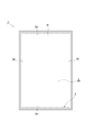
- the wall 3 rises from the rising portion 2a of the foundation 2 and surrounds the indoor space S in plan view. That is, the wall 3 separates the external space and the internal space of the masonry building 1 to form an indoor space S.
- the wall body 3 is a cantilever structure having a fixed end on the foundation 2 side and a free end on the upper end side.
- the wall body 3 is comprised by the 1st wall body 3a, the 2nd wall body 3b, the 3rd wall body 3c, and the 4th wall body 3d.
- the wall body 3 has a rectangular frame shape in plan view.
- the number of the wall bodies which comprise the wall body 3 is not limited to four like the 1st wall body 3a to the 4th wall body 3d, but if it is the shape surrounding the indoor space S, it will be four or more wall bodies It may be constituted by.
- the wall 3 has a strength capable of resisting a load acting on the divided area for each divided area virtually divided into a plurality of parts in plan view.
- the divided region may be, for example, the first wall body 3a, the second wall body 3b, the third wall body 3c, and the fourth wall body 3d, and is divided smaller than these first wall bodies 3a and the like. It may be a region that has been changed.
- the masonry building 1 is subjected to structural calculation for each of these divided areas.
- the wall 3 is formed by stacking a plurality of and a plurality of types of stacked units 30.
- the masonry unit 30 is formed in a substantially rectangular plate shape (substantially rectangular parallelepiped shape) by previously combining a plurality of blocks 31 having a common height and thickness and different lengths.
- the block 31 has a substantially rectangular parallelepiped shape.
- the material of the block 31 is, for example, ALC (lightweight cellular concrete) or lightweight concrete.
- a plurality of the blocks 31 constituting the masonry unit 30 are combined in the height direction of the block 31 and the length direction of the block 31. That is, the blocks 31 are not combined in the thickness direction of the block 31.
- the thickness direction of the block 31 is the thickness direction of the masonry unit 30 when the masonry unit 30 is formed by the block 31. That is, the thickness direction of the block 31 is the direction from the indoor side toward the outdoor side (the left-right direction in FIG. 1) when the wall body 3 is formed by the masonry unit 30. Further, the length direction of the block 31 is a direction perpendicular to the height direction of the block 31 and the thickness direction of the block 31 (left-right direction in FIG. 4A).
- each of the blocks 31 constituting the masonry unit 30 is equal to the planar module M.
- the dimension in the length direction of each block 31 is set to an integral multiple of the planar module M.
- the blocks 31 constituting the masonry unit 30 are arranged in a staggered manner so that the vertical joints between adjacent blocks in the length direction of the block 31 are shifted by an integral multiple of the planar module M. That is, the vertical joints between the blocks 31 are not continuous in the vertical direction, and the vertical joints between the blocks 31 are shifted by an integral multiple of the planar module M in the horizontal direction.
- the horizontal direction is the horizontal direction.
- the masonry unit 30 has a length in the length direction of the block 31 (the left-right direction in FIGS. 4A to 4C).
- a plurality of different variations are provided.
- the masonry unit 30B shown in FIG. 4B is longer than the masonry unit 30A shown in FIG.
- the masonry unit 30C shown in FIG. 4 (c) is longer than the masonry unit 30B shown in FIG. 4 (b).
- a plurality of types of masonry units 30A, 30B and 30C can be formed.
- the length of the block 31 is set to an integral multiple of the planar module M
- the lengths of the masonry units 30A, 30B and 30C formed by combining the blocks 31 are also integral multiples of the planar module M.
- 4A to 4C show three types of variations of the masonry unit 30 having different lengths
- the number of variations of the masonry unit 30 is not limited to three types.
- the masonry unit 30 may have a plurality of variations having different heights. In this case, when combining the blocks 31, by changing the number of blocks 31 stacked in the height direction (longitudinal direction), a plurality of variations of the stacked units 30 having different heights can be obtained.
- the wall 3 is formed by stacking a plurality of types of masonry units 30 having different lengths such as the masonry units 30A, 30B, and 30C described above in the vertical direction and the horizontal direction. Yes.
- the masonry units 30 adjacent in the horizontal direction have the same height.
- FIG. 5 shows only the wall 3 of the first floor portion of the masonry building 1.
- the masonry units 30 constituting the wall body 3 are arranged in a staggered manner so that the vertical joints between the masonry units 30 adjacent in the horizontal direction are shifted by an integral multiple of the planar module M. That is, the vertical joints between the masonry units 30 are not continuous in the vertical direction, and the vertical joints between the masonry units 30 are shifted by an integral multiple of the planar module M in the horizontal direction.
- the vertical joints between the masonry units 30 are not limited to being arranged in a staggered manner so as to be an integral multiple of the plane module M, but between the masonry units 30 shown in FIGS. 5 and 11. As shown in the vertical joint B, the vertical joint may be continuous in the vertical direction.
- the masonry unit 30 includes a vertical bar 32, a high nut 33, and a washer 34 in addition to the block 31.
- a lower recess 31b is provided on the lower surface of the block 31.
- the lower recess 31 b extends in the length direction of the block 31.
- a side recess 31 c is formed on the end surface in the length direction of the block 31.
- the side recess 31 c extends along the height direction of the block 31.
- the block 31 is provided with a plurality of vertical holes 31a penetrating in the vertical direction.
- the vertical holes 31a provided in each block 31 communicate in the vertical direction.
- vertical bars 32 are passed through predetermined vertical holes 31a.
- a male screw 32 a is provided at the upper end of the vertical bar 32.
- a male screw 32 b is provided at the lower end of the vertical bar 32.
- a washer 34 is disposed at a position of the vertical hole 31a through which the vertical streak 32 passes between the blocks 31 adjacent to each other in the vertical direction.
- a washer 34 is disposed between the block 31 at the second level from the top and the block 31 at the third level from the top. Further, the washer 34 is arranged in the lower recessed portion 31b in the second stage from the top.
- the washer 34 is provided with a vertical line insertion hole 34a through which the vertical line 32 passes.
- the washer 34 is provided with a plurality of grout holes 34b for allowing the grout to pass through, as will be described in detail later.
- the outer diameter of the washer 34 is larger than the diameter of the vertical hole 31a through which the vertical bar 32 passes.
- the high nut 33 is screwed into the male screw 32 b at the lower end of the vertical bar 32.
- the female screw 33a of the high nut 33 faces downward.
- the outer diameter of the high nut 33 is larger than the diameter of the vertical bar insertion hole 34a of the washer 34 and smaller than the diameter of the vertical hole 31a through which the vertical bar 32 passes.
- the adjacent blocks 31 in the vertical direction and the horizontal direction are fixed to each other by the grout G1.
- the blocks 31 are fixed to each other by pouring the grout G1 into the hole formed by the side recess 31c of the uppermost block 31. Is done.
- the grout G1 poured into the hole formed by the side recess 31c of the uppermost block 31 flows downward through the hole formed by the side recess 31c and passes through the lower recess 31b of the block 31.
- all the blocks 31 constituting the masonry unit 30 are fixed to each other.
- the grout G1 is not filled in the vertical hole 31a, and the vertical streaks 32 can move up and down and rotate in the vertical hole 31a.
- the vertical hole 31a in which the vertical streak 32 is not provided can be used as, for example, a wiring hole 3f for electric wiring described later.
- packing 35 is arrange
- the packing 35 can employ various shapes as long as the grout G1 can be prevented from flowing into the vertical hole 31a.
- a stopper 36 is provided at a portion where the washer 34 is provided. Like the packing 35, the stopper 36 prevents the grout G1 from flowing into the vertical hole 31a in which the washer 34 is disposed. As long as the stopper 36 is configured to prevent the grout G1 from flowing into the vertical hole 31a in which the washer 34 is disposed, various shapes can be adopted.
- a tape 37 is attached to the upper surface of the lowermost block 31 so as to cover the hole portion formed by the lateral recess 31c of the lowermost block 31. This prevents the grout G1 from leaking from the lower end of the masonry unit 30 through the gap between the lowermost blocks 31 when the grout G1 is poured. 6 (a) and 6 (b), the packing 35, the stopper 36 and the tape 37 are shown in black for emphasizing the installation position. Is arranged.
- the masonry unit 30 can be formed in advance in the factory. A plurality of types of masonry units 30 are formed in advance.
- a method for forming the masonry unit 30 will be described.
- the lower blocks 31 below the washer 34 are assembled.
- the tape 37 is affixed so as to cover the hole formed by the side recess 31c of the lowermost block 31.
- the stopper 36 is installed at the position where the washer 34 is provided, and the packing 35 is installed at the position of the vertical hole 31a where the vertical stripe 32 is not inserted.
- the vertical bar 32 to which the high nut 33 is attached is inserted into a predetermined vertical hole 31a.
- the washer 34 is passed through the longitudinal bars 32 and the washer 34 is placed on the upper surface of the assembled block 31. After the washer 34 is placed, the blocks 31 above the washer 34 are stacked.
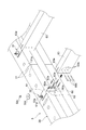
- an eye nut (lifting auxiliary jig) 38 may be screwed onto the male screw 32 a at the upper end of the vertical bar 32.
- the eye nut 38 can be used as a jig for lifting the masonry unit 30.
- the masonry unit 30 may be lifted by attaching a wire to the eye nut 38 and hooking the hook of the crane 5 on the wire.
- the lifting auxiliary jig attached to the vertical bars 32 is not limited to the eyenut 38, and may be a jig having another shape such as a hook shape.
- the left vertical streak 32 shows a state before being pulled up
- the right vertical streak 32 shows a state after being lifted.
- the grout G1 is not filled in the vertical hole 31a through which the vertical streak 32 is passed before the masonry unit 30 is assembled.
- the vertical bar 32 is pulled up using the eye nut 38 or the like
- the high nut 33 comes into contact with the washer 34
- the washer 34 comes into contact with the lower surface of the block 31 immediately above the washer 34. From this state, the masonry unit 30 can be lifted by further lifting the vertical bars 32.
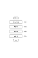
- the operator screws the eye nut 38 into the male screw 32 a provided at the upper end of the vertical bar 32.
- the operator uses the crane 5 or the like to lift the masonry unit 30 using the eye nut 38 (S101: lifting process).
- the operator can set the position of the vertical bars 32 of the raised masonry unit 30 and the vertical bars 32 protruding from the upper surface of the lower masonry unit 30 (lower structure) on which the raised masonry unit 30 is placed.
- the suspended masonry unit 30 is placed on the upper surface of the lower masonry unit 30 while aligning with the position.
- the operator removes the eye nut 38 from the vertical bar 32 (S ⁇ b> 102: placement step).
- the dimension from the lower end of the high nut 33 to the lower surface of the lowermost block 31 is the vertical length protruding from the upper surface of the lower masonry unit 30. It is larger than the protruding dimension of the line 32.
- the operator rotates the vertical bar 32 of the mounted masonry unit 30, and causes the female screw 33 a of the high nut 33 attached to the lower end of the rotated vertical bar 32 to move from the upper surface of the lower masonry unit 30. It is screwed into the male screw 32a of the protruding vertical bar 32 (S103: screwing step). Thereby, the vertical bars 32 of the upper and lower masonry units 30 are connected by the high nut 33.
- the operator passes the joints between the masonry units 30 adjacent in the vertical direction and the horizontal direction, and the vertical bars 32 as shown in the right part of FIG.
- the male threads 32a are filled with grout to fix the masonry units 30 together (S104: fixing process).
- Filling the joint between the masonry units 30 with grout means filling the grout into the hole formed by the side recess 31 c at the end of the adjacent masonry unit 30.
- the grout hole 34b is provided in the washer 34, when grout is filled into the vertical hole 31a through which the vertical streak 32 is passed, the grout can be easily flowed to the lower end of the vertical hole 31a.
- the upper masonry unit 30 is mounted on the masonry unit 30 to which the nut 32c is screwed. Put. This operation is performed until the masonry unit 30 is placed to a desired height position.
- the present invention is not limited to this, and the masonry unit 30 is switched so that the winning and losing of one wall body and the winning and losing of the other wall body are alternately switched every time the masonry unit 30 is placed. You may combine. Also, as with the exit corner, the masonry unit 30 is arranged so that one of the entrance corners wins and the other loses. Similarly, the masonry unit 30 is combined so that the winning and losing of one wall body and the winning and losing of the other wall body are alternately switched every time the masonry unit 30 is placed at the corner. Also good.
- An upper masonry unit 30 (masonry unit 30C in the example of FIG. 5) is laminated on the upper part of the wall opening 3e so as to straddle the separated masonry units 30.
- the masonry unit 30 disposed at the upper part of the wall opening 3e functions as a magnet.
- the masonry unit 30 that functions as a magsa may be formed of a magsa block that has the same shape and high bending strength as the block 31 that constitutes the other masonry unit 30.
- the block for the magsa may be a block having a large amount of reinforcing bars arranged inside the block 31 constituting the other masonry unit 30.
- the wall opening part 3e was provided in the wall 3 by separating the masonry units 30 adjacent in the horizontal direction, the wall opening part 3e is formed by separating the blocks 31 adjacent in the horizontal direction. May be.
- the connecting piece 62 extends downward from the indoor end of the horizontal piece 61.
- the connecting piece 62 is in contact with the indoor side surface of the wall 3.
- the connecting piece 62 is fixed to the masonry unit 30 with screws 62a.
- the support member 60 extends horizontally from the indoor side surface of the connecting piece 62 toward the indoor side. That is, the support member 60 extends from the horizontal piece 61 through the connecting piece 62 toward the indoor side.
- the support member 60 is formed in a plate shape.
- the support member 60 stands in the vertical direction from the surface of the wall 3 on the indoor side, and is connected to the connection piece 62 so that the front and back surfaces face the horizontal direction.
- the support member 60 has a plurality of pin insertion portions 60a formed by holes and notches.
- the second floor beam 63 and the support member 60 are connected by the pin hole 63b and the pin 60b inserted into the pin insertion portion 60a.
- a structural plywood 64 and a floor finishing material 65 are installed on the upper surface of the second-floor floor beam 63.
- a ceiling surface opening R is provided on the surface including the upper end of the wall body 3.
- the ceiling surface opening R is covered by a roof 4 supported by the upper end of the wall 3.
- the end of the roof beam 41 is connected to the girder 50.
- a structural plywood 42 is installed on the upper surface of the roof beam 41 so as to cover the ceiling surface opening R.
- an inclination member for forming a roof gradient, a waterproof sheet, and the like are installed on the structural plywood 42.
- the roof 4 includes the roof beam 41, the structural plywood 42, the tilting member, the waterproof sheet, and the like.
- a heat insulating material may be disposed on the lower surface of the structural plywood 42.
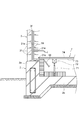
- a bundle 71 is installed on the bottom plate portion 2 b of the foundation 2.
- the bundle 71 supports the large pull 72.
- a structural plywood 73 and a floor finishing material 74 constituting the first floor 7 are installed on the large pull 72.
- a heat insulating material may be disposed in the vicinity of the inner side surface of the rising portion 2a.
- the lower end position of the first floor 7 (the height position of the lower surface of the structural plywood 73) is higher than the lower end position of the wall 3.
- a wiring hole 3 f for electrical wiring that communicates in the vertical direction is provided inside the wall body 3.
- the wiring hole 3f is configured by a predetermined vertical hole 31a among a plurality of vertical holes 31a provided in each block 31 and communicating in the vertical direction.
- An electric wiring cable 55 is passed through the wiring hole 3f.
- the cable 55 can be wired in the vertical direction.
- a lateral hole 31 e communicating with the wiring hole 3 f is provided on the surface of the wall 3 on the indoor side.
- the lateral hole 31e can draw out the cable 55 passing through the wiring hole 3f to the indoor side.
- the lateral hole 31e can be provided at a desired height position at a position above the first floor 7. That is, the lateral hole 31e can be provided at a desired height position where the cable 55 is desired to be pulled out.
- the present embodiment is configured as described above, and the wall 3 constituting the masonry building 1 has a fixed end on the foundation 2 side and a free end on the upper end side.
- the wall 3 has a strength capable of resisting a load acting on the divided area for each divided area virtually divided into a plurality of parts in plan view. Thereby, required intensity
- the wall body 3 may be configured by the stacked blocks 31 and the vertical bars 32 passed through the vertical holes 31 a of the blocks 31.
- the wall body 3 can be configured so that only a height (the number of steps of the block 31) is different with a common fit. Therefore, it is possible to easily perform the structural calculation of the wall body 3 having only different heights. For example, by creating in advance a formula for structural calculation using the height (number of steps) of the block 31 as a variable, it is possible to easily perform structural calculation simply by applying the height (number of steps) to the created formula. .
- the vertical streak 32 is arrange
- the second floor 6 of the masonry building 1 is supported by a support member 60 provided on the indoor side surface of the wall 3.
- the height position of the second floor 6 can be easily changed only by changing the height position where the support member 60 is provided.
- the support member 60 extends from the horizontal piece 61 inserted into the horizontal joint between the blocks 31 toward the indoor side via the connecting piece 62.
- the height position of the second floor 6 can be easily changed simply by changing the height position at which the horizontal piece 61 is inserted into the horizontal joint between the blocks 31. Further, since the horizontal piece 61 is fastened to the vertical bar 32, the second floor 6 can be firmly fixed to the wall 3.
- a masonry unit 30 that functions as a magsa is bridged over the wall opening 3e provided in the wall 3.
- the masonry unit 30 that functions as a magsa may be configured by a magsa block having the same shape as the block 31 and a bending strength greater than that of the block 31.
- the magusa portion can also have the same finish as the other wall portions, and the masonry building 1 can be made using the texture.
- the ceiling surface opening R provided on the surface including the upper end of the wall 3 is covered with the roof 4 supported by the upper end of the wall 3.
- the wall body 3 is a cantilever structure having a fixed end on the foundation 2 side and a free end on the upper end side. For this reason, even if it has the ceiling surface opening R in the surface including the upper end of the wall 3, structural safety can be maintained.
- the fixed end means an end portion that is not easily shaken when subjected to a horizontal force and is firmly fixed
- the free end is an end provided in such a manner as to allow the shake when subjected to a horizontal force.
- the lower end of the wall body 3 is a fixed end fixed to the foundation 2, and the upper end is covered with the roof 4, but is a free end because it is provided in a manner that allows shaking.
- a groove 31 d extending along the extending direction of the upper end surface of the wall 3 is provided on the upper surface of the upper end block 31 ⁇ / b> A located at the top of the wall 3.
- a girder 50 is disposed in the groove 31d.
- the girder 50 is fixed to the wall 3 by a grout G2 filled in the groove 31d while being kept horizontal by the level adjusting piece 51.
- the roof 4 can be constructed with high accuracy by providing the girder 50 on the upper end surface of the wall 3 that is likely to have uneven heights.
- the girder 50 also has a function of maintaining the integrity of the wall bodies 3 in the same plane.
- a wiring hole 3f for electrical wiring Inside the wall body 3 is provided a wiring hole 3f for electrical wiring that communicates in the vertical direction.
- the cable 55 in the wiring hole 3f can be pulled out from the lateral hole 31e.
- the cable 55 for a switch or outlet the cable 55 is inserted into the wiring hole 3f, the cable is sent downward, and the cable 55 passing through the wiring hole 3f is extracted from the lateral hole 31e.
- the inner peripheral surface of the wiring hole 3f serves as a guide when the cable 55 is sent, wiring work can be performed easily and accurately.
- the horizontal hole 31e can be provided in a desired height position, the height of a switch or an outlet can be set freely.
- the lower end position of the first floor 7 is higher than the lower end position of the wall 3, and the wiring hole 3 f extends to a position below the lower end position of the first floor 7.
- the horizontal hole 31e in the vicinity of the lower end position of the wall 3, the underfloor space of the first floor 7 and the wiring hole 3f can be communicated with each other via the horizontal hole 31e.
- the space can be used as a space for laterally pulling the cable 55.
- the second floor 6 is not limited to the structure supported using the support member 60 shown in FIG.
- the wide block 31B has a portion that is wider (thickness) than the block 31 stacked on the upper side of the wide block 31B and protrudes more indoors than the block 31 stacked on the upper side.
- the end of the second-floor floor beam 63 of the second-floor 6 is supported by the portion of the wide block 31B that protrudes to the indoor side.
- the structural plywood 64 and the floor finishing material 65 are installed on the upper surface of the second-floor floor beam 63.
- the wide block 31B is formed using the same material as the block 31 and the like. By supporting the second floor 6 using the wide block 31B, the height position of the second floor 6 can be easily changed only by changing the height position where the wide block 31B is stacked. Furthermore, by using the wide block 31B, the wide block 31B does not become a thermal bridge, and the masonry building 1 excellent in heat can be obtained.
Landscapes
- Engineering & Computer Science (AREA)
- Architecture (AREA)
- Physics & Mathematics (AREA)
- Electromagnetism (AREA)
- Civil Engineering (AREA)
- Structural Engineering (AREA)
- Building Environments (AREA)
- Joining Of Building Structures In Genera (AREA)
- Conveying And Assembling Of Building Elements In Situ (AREA)
Abstract
La présente invention concerne un bâtiment qui comprend une fondation et des murs qui s'élèvent à partir de la fondation et qui entourent l'espace intérieur en vue en plan. Les murs sont des structures en porte-à-faux qui possèdent des extrémités fixes sur le côté fondation et des extrémités libres sur le côté extrémité supérieure.
Applications Claiming Priority (2)
| Application Number | Priority Date | Filing Date | Title |
|---|---|---|---|
| JP2015120957A JP6573490B2 (ja) | 2015-06-16 | 2015-06-16 | 建物 |
| JP2015-120957 | 2015-06-16 |
Publications (1)
| Publication Number | Publication Date |
|---|---|
| WO2016204228A1 true WO2016204228A1 (fr) | 2016-12-22 |
Family
ID=57545287
Family Applications (1)
| Application Number | Title | Priority Date | Filing Date |
|---|---|---|---|
| PCT/JP2016/067936 Ceased WO2016204228A1 (fr) | 2015-06-16 | 2016-06-16 | Bâtiment |
Country Status (2)
| Country | Link |
|---|---|
| JP (1) | JP6573490B2 (fr) |
| WO (1) | WO2016204228A1 (fr) |
Cited By (1)
| Publication number | Priority date | Publication date | Assignee | Title |
|---|---|---|---|---|
| JP2018105096A (ja) * | 2016-12-28 | 2018-07-05 | 旭化成ホームズ株式会社 | 建物 |
Citations (4)
| Publication number | Priority date | Publication date | Assignee | Title |
|---|---|---|---|---|
| JPH0529286Y2 (fr) * | 1985-07-05 | 1993-07-27 | ||
| JPH0874379A (ja) * | 1994-08-22 | 1996-03-19 | Giso Rin | 縦横方向に中空な壁構成部材 |
| JP2003056061A (ja) * | 2001-08-10 | 2003-02-26 | Yoshihiro Tokai | 木造建築物 |
| JP3749825B2 (ja) * | 2000-09-06 | 2006-03-01 | 独立行政法人科学技術振興機構 | 煉瓦組積構造、煉瓦組積工法及び煉瓦 |
Family Cites Families (1)
| Publication number | Priority date | Publication date | Assignee | Title |
|---|---|---|---|---|
| JP3673517B2 (ja) * | 2002-03-06 | 2005-07-20 | 独立行政法人科学技術振興機構 | 建築物の壁体構造 |
-
2015
- 2015-06-16 JP JP2015120957A patent/JP6573490B2/ja active Active
-
2016
- 2016-06-16 WO PCT/JP2016/067936 patent/WO2016204228A1/fr not_active Ceased
Patent Citations (4)
| Publication number | Priority date | Publication date | Assignee | Title |
|---|---|---|---|---|
| JPH0529286Y2 (fr) * | 1985-07-05 | 1993-07-27 | ||
| JPH0874379A (ja) * | 1994-08-22 | 1996-03-19 | Giso Rin | 縦横方向に中空な壁構成部材 |
| JP3749825B2 (ja) * | 2000-09-06 | 2006-03-01 | 独立行政法人科学技術振興機構 | 煉瓦組積構造、煉瓦組積工法及び煉瓦 |
| JP2003056061A (ja) * | 2001-08-10 | 2003-02-26 | Yoshihiro Tokai | 木造建築物 |
Cited By (1)
| Publication number | Priority date | Publication date | Assignee | Title |
|---|---|---|---|---|
| JP2018105096A (ja) * | 2016-12-28 | 2018-07-05 | 旭化成ホームズ株式会社 | 建物 |
Also Published As
| Publication number | Publication date |
|---|---|
| JP2017002685A (ja) | 2017-01-05 |
| JP6573490B2 (ja) | 2019-09-11 |
Similar Documents
| Publication | Publication Date | Title |
|---|---|---|
| US12297638B2 (en) | Frame, basic framework, module, profile and set of structural elements for modular construction and a modular-construction building | |
| CN101622405B (zh) | 外墙板及其安装方法 | |
| JP2019509415A5 (fr) | ||
| CN1981102A (zh) | 具有可变长度墙连接件的隔离混凝土成形方法 | |
| KR102197689B1 (ko) | 수평으로 조립 설치되는 수직코아구조물 및 그 시공방법 | |
| WO2020214086A1 (fr) | Bâtiment préfabriqué | |
| CN101925710B (zh) | 拼板化系统和方法 | |
| JP6499526B2 (ja) | 組積ユニット及び組積方法 | |
| JP6573490B2 (ja) | 建物 | |
| JP5806028B2 (ja) | 組積造建物 | |
| US8667751B2 (en) | Set of elements for constructing a wooden wall and method for using such elements | |
| US20190177975A1 (en) | Structural element | |
| WO2016204219A1 (fr) | Construction de maçonnerie | |
| JP2024519114A (ja) | かみ合わせ可能な壁補強パネル、壁補強アセンブリ、及び壁補強のための方法 | |
| JP5958984B1 (ja) | グリッド設計法に基づく木造建築物の製造方法 | |
| EP3219865A1 (fr) | Panneau modulaire structurel en système de composant de construction et son procédé de construction | |
| RU2422603C1 (ru) | Блок несъемной опалубки перекрытия | |
| JP2019035250A (ja) | 床を形成する床板ラチス梁 | |
| JP3187977U (ja) | プレキャストコンクリート造純ラーメンフレーム構造による板状型住宅建築物 | |
| EP4055230B1 (fr) | Ensemble de construction | |
| RU2597651C1 (ru) | Перекрытие деревянное и плита деревянная для этого перекрытия | |
| KR20110103632A (ko) | 건식벽체 및 그 시공 방법 | |
| JP5806033B2 (ja) | 組積造建物の臥梁用の外枠材、及び組積造建物 | |
| JP2009114639A (ja) | 構造物 | |
| CN120936775A (zh) | 用于建筑学构建尤其是框架式房屋的结构构件、铺设及墙 |
Legal Events
| Date | Code | Title | Description |
|---|---|---|---|
| 121 | Ep: the epo has been informed by wipo that ep was designated in this application |
Ref document number: 16811702 Country of ref document: EP Kind code of ref document: A1 |
|
| NENP | Non-entry into the national phase |
Ref country code: DE |
|
| 122 | Ep: pct application non-entry in european phase |
Ref document number: 16811702 Country of ref document: EP Kind code of ref document: A1 |