WO2016207984A1 - ボタンバック及びボタン - Google Patents
ボタンバック及びボタン Download PDFInfo
- Publication number
- WO2016207984A1 WO2016207984A1 PCT/JP2015/068100 JP2015068100W WO2016207984A1 WO 2016207984 A1 WO2016207984 A1 WO 2016207984A1 JP 2015068100 W JP2015068100 W JP 2015068100W WO 2016207984 A1 WO2016207984 A1 WO 2016207984A1
- Authority
- WO
- WIPO (PCT)
- Prior art keywords
- button
- bent
- bent portion
- umbrella
- button back
- Prior art date
- Legal status (The legal status is an assumption and is not a legal conclusion. Google has not performed a legal analysis and makes no representation as to the accuracy of the status listed.)
- Ceased
Links
Images





Classifications
-
- A—HUMAN NECESSITIES
- A44—HABERDASHERY; JEWELLERY
- A44B—BUTTONS, PINS, BUCKLES, SLIDE FASTENERS, OR THE LIKE
- A44B1/00—Buttons
- A44B1/02—Buttons characterised by their material
-
- A—HUMAN NECESSITIES
- A44—HABERDASHERY; JEWELLERY
- A44B—BUTTONS, PINS, BUCKLES, SLIDE FASTENERS, OR THE LIKE
- A44B1/00—Buttons
- A44B1/18—Buttons adapted for special ways of fastening
- A44B1/28—Buttons adapted for special ways of fastening with shank and counterpiece
Definitions
- the present invention relates to a button back and a button, and more particularly, to a button back that is a component part of a button frequently used in jeans and the like, and a button using the button back.
- buttons As a button often used for jeans, jean, etc., there is a type that has a substantially cylindrical body and a head that expands in a disk shape at one end of the body, and the head is inserted into and removed from the button hole.
- a button is disclosed in, for example, US Patent Application Publication No. 2007/0226959 (Patent Document 1).
- This type of button is generally composed of three parts: a button back and shell cap, which are metal outer shell members, and an insert, which is a resin or metal core member.
- the button back includes a cylindrical portion that forms an outer peripheral wall of the body portion of the button, and an umbrella portion that extends radially outward from one end of the cylindrical portion and forms the back side wall of the button head.
- the umbrella portion is generally press-molded so that the radially outer end thereof is curved to the opposite side of the cylindrical portion. Thereby, while the thickness for arrange
- the shell cap has a disc portion that forms the front side wall of the button head portion, and a bent portion that is bent from the radially outer end of the disc portion toward the back side of the head portion. The bent portion is crimped to the curved radially outer end of the umbrella portion of the button back.
- the surface of the disk portion of the shell cap becomes the surface of the head of the button. Generally, a logo or design made up of letters, figures, symbols, etc. with a circumferential direction determined is given to this surface. Such a button is attached to jeans or the like in a predetermined circumferential direction.
- Patent Document 1 proposes that the outer periphery of the umbrella portion of the button back has a polygonal shape (see FIG. 9), and that the corners of the polygon function as a rotation stop. ing.
- the bent portion of the shell cap is bent along the polygonal shape of the umbrella portion, so that there is a problem that the button surface is difficult to be a beautiful circle.
- buttons back having a function of preventing the rotation of the shell cap
- a button back having a plurality of convex portions in the circumferential direction that are prevented from rotating at the curved radial outer end of the umbrella is known.
- the mold becomes complicated and the manufacturing cost increases.
- the button back is manufactured from a conventional brass material by using aluminum or an aluminum alloy.
- an object of the present invention is to provide a button back that can make the surface of the button a beautiful perfect circle, the shell cap is difficult to turn around, and the umbrella part is difficult to deform, and a button using such a button back. It is to provide.
- a metal button back including a tubular portion and an umbrella portion extending radially outward (radially) from one axial end of the tubular portion
- the umbrella portion includes a first bent portion that extends radially outward from one axial end of the tubular portion and then bends to the opposite side of the tubular portion, and the radially outer end of the first bent portion
- the outer periphery including a polygonal shape having three or more corner portions and a side portion extending between two corner portions adjacent to each other in the circumferential direction, and the umbrella portion corresponds to the first side portion.
- a button back including a flat plate portion extending radially outward from a radially outer end of the bent portion is provided.
- the button back can be manufactured from a metal such as copper or copper alloy, aluminum or aluminum alloy, zinc or zinc alloy, nickel or nickel alloy, but is not limited thereto. Further, as will be described later, the button back can be made of aluminum or an aluminum alloy in order to reduce the material cost of the button back.
- the umbrella portion includes a first bent portion having a polygonal shape having three or more corners and side portions on the outer periphery, and radially outer ends of the respective side portions of the first bent portion. And a flat plate portion extending from.
- the combination of the polygonal curved portion and the flat plate portion can increase the strength or rigidity of the umbrella portion. Therefore, even if the button back is manufactured from aluminum or aluminum alloy which is easier to deform than the brass material, the umbrella portion can be made difficult to deform.
- the first bent portion can be, for example, a portion bent in a curved shape, but is not limited thereto.
- the flat plate portion forms an outer periphery of a perfect circle connecting the corner portions.
- the distance that the flat plate portion extends from the radially outer end of the first bent portion to the radially outer side is substantially zero at the corner, and is intermediate between the two corners adjacent in the circumferential direction. It becomes the maximum at the circumferential intermediate point of each side.
- the shape of the radially outer end of the button back umbrella portion becomes a perfect circle by the flat plate portion, when the second bent portion of the shell cap is attached to the radially outer end portion of the button back umbrella portion, The second bent portion of the shell cap can be bent into a perfect circle along the outer periphery of the flat plate portion. For this reason, the button surface tends to be a beautiful perfect circle.
- the second bent portion of the shell cap is crimped so as to come into contact with the first bent portion of the umbrella portion of the button back.
- the degree of bending of the second bent portion of the shell cap is the first. 1 is the smallest at each corner of the bent portion, and the largest at the circumferential intermediate point of each side portion.
- the degree of bending of the second bent portion of the shell cap is alternately changed in the circumferential direction by the corner portion and the side portion, so that the shell cap is difficult to turn with respect to the button back.
- the outer periphery of the first bent portion has a polygonal shape having eight to twelve corners.
- the optimum polygonal shape that contributes to increasing the strength or rigidity of the first bent portion of the umbrella portion was found to be as follows depending on the size of the button from a test or the like.
- the radius of curvature of the first bent portion is 1 mm or less.
- the radius of curvature of the first bent portion can be set to be the same for both the corner and the side.
- the lower limit of the radius of curvature of the first bent portion is the thickness of the first bent portion, for example, 0.3 mm.
- the effect can be enhanced. If the radius of curvature of the first bent portion exceeds 1 mm, it is necessary to bend the second bent portion of the shell cap more than necessary, or the second bent portion and the first bent portion that are crimped There is a possibility that the gap formed between the two and the shell cap is too large and the shell cap is likely to turn around the umbrella portion.
- the extension length of the flat plate portion is the longest at the center portion among the lengths of the side portions, and gradually decreases toward the corner portion adjacent to the side portions.
- the extension length from the side portion of the flat plate portion is a length extending in a direction perpendicular to the side portion of the flat plate portion.
- the extension length from the side portion of the flat plate portion is the longest at the center portion (the middle point in the circumferential direction of the side portion) among the lengths of the side portions, toward the corner portion adjacent to the side portion from this center portion. Decrease gradually.
- the button back is made of aluminum or an aluminum alloy.
- the cost can be reduced as compared with the brass material, but the button back easily deforms.
- the strength or rigidity of the umbrella portion is increased by providing the umbrella portion with the first bent portion whose outer periphery is polygonal and the flat plate portion extending from the radially outer end of the side portion of the first bent portion. It is possible to apply a detent to the shell cap.
- a button including a metal button back and a metal shell cap assembled to the button back the button back includes a tube portion and one axial end of the tube portion.
- An umbrella portion extending radially outward from the umbrella portion, the umbrella portion including a first bent portion that extends radially outward from one axial end of the tube portion and then bends to the opposite side of the tube portion;
- the outer periphery including the radially outer end of the first bent portion is a polygonal shape having three or more corner portions and a side portion extending between two corner portions adjacent to each other in the circumferential direction, and the umbrella portion Includes a flat plate portion extending radially outward from a radially outer end of the first bent portion corresponding to the side portion
- the shell cap includes a disk portion defining a button surface, and a disk portion Bent from the radially outer end, the radial direction of the button back umbrella And a second bent portion that is crimped to a side portion, and the degree of
- the button according to the present invention uses the button back according to the present invention described above, and the degree of bending of the second bent portion of the shell cap is more than the side portion than the corner portion of the first bent portion. It is characterized by being large. As described above, the degree of bending of the second bent portion of the shell cap is alternately changed in the circumferential direction by the corner portion and the side portion, so that the shell cap is difficult to turn with respect to the button back.
- the shell cap can be manufactured from a metal such as copper or copper alloy, aluminum or aluminum alloy, zinc or zinc alloy, nickel or nickel alloy, but is not limited thereto.
- the flat plate portion forms an outer periphery of a perfect circle connecting the corner portions.
- the distance that the flat plate portion extends from the radially outer end of the first bent portion to the radially outer side is substantially zero at the corner, and is intermediate between the two corners adjacent in the circumferential direction. It becomes the maximum at the circumferential intermediate point of each side.
- the shape of the radially outer end of the button back umbrella portion becomes a perfect circle by the flat plate portion, when the second bent portion of the shell cap is attached to the radially outer end portion of the button back umbrella portion, The second bent portion of the shell cap can be bent into a perfect circle along the outer periphery of the flat plate portion. For this reason, the button surface tends to be a beautiful perfect circle.
- the caulking form of the second bent portion of the shell cap is alternately different with respect to the circumferential direction. That is, the second bent portion of the shell cap has a different crimping form between a portion crimped to the corner portion of the first bent portion of the button back and a portion crimped to the side portion. Such a difference in the caulking form occurs alternately in the circumferential direction according to corners and sides that alternate in the circumferential direction of the first bent portion. This makes it difficult for the shell cap to turn around the button back umbrella.
- a bending angle of the second bent portion of the shell cap is different between a portion corresponding to the side portion and a portion corresponding to the corner portion, and in the portion corresponding to the side portion, A space portion is formed between the two bent portions and the side portion.
- the bending angle of the second bent portion of the shell cap is larger than the corner portion with respect to the side portion where the flat plate portion is present with respect to the first bent portion of the button back.
- a space portion is formed between the second bent portion of the shell cap and the side portion of the first bent portion of the button back.
- the first bent portion includes a vertical portion that reaches a radially outer end of the first bent portion and is substantially parallel to the axial direction of the button back, and the shell cap
- the second bend is at least partially in contact with the vertical portion.
- the umbrella portion has a first bent portion having a polygonal shape having three or more corners and side portions on the outer periphery, and a flat plate portion extending from the radially outer end of each side portion of the first bent portion.
- the strength or rigidity of the umbrella portion can be increased, and the degree and angle of bending of the first bent portion of the shell cap or the caulking form alternately change in the circumferential direction by the corner portion and the side portion. To do. Therefore, it becomes difficult for the shell cap to turn around the button back.
- the flat plate portion forms an outer periphery of a perfect circle connecting the corner portions
- the shape of the radially outer end of the umbrella portion of the button back becomes a perfect circle by the flat plate portion.
- the second bent portion of the shell cap can be bent into a perfect circle along the outer periphery of the flat plate portion. For this reason, the button surface tends to be a beautiful perfect circle.
- FIG. 1 is a bottom view of a button according to an embodiment of the present invention.
- 2 is a cross-sectional view taken along line AA in FIG. 3 is a cross-sectional view taken along line BB in FIG.
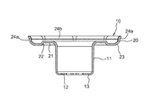
- FIG. 4 is a perspective view of the button back.
- FIG. 5 is a bottom view of the button back.
- 6 is a cross-sectional view taken along line AA in FIG. 7 is a cross-sectional view taken along line BB in FIG.
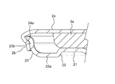
- FIG. 8 is an enlarged view showing a crimped state of the shell cap in a cross section corresponding to the corner of the curved portion of the umbrella portion.
- FIG. 9 is an enlarged view showing a caulked state of the shell cap in a cross section corresponding to the midpoint of the side portion of the curved portion of the umbrella portion.
- FIG. 10 is a cross-sectional view of a button stopper used when attaching the button to the fabric.
- FIG. 1 is a bottom view of a button 1 according to an embodiment of the present invention.
- 2 and 3 are a cross-sectional view taken along line AA and a cross-sectional view taken along line BB in FIG.
- the vertical direction of the button 1 is based on the paper surface of FIGS.
- the button 1 is frequently used for jeans and the like, and has a substantially cylindrical body 1a and a head 1b that expands in a disk shape radially outward on the upper end side of the body 1a.
- the button 1 is of a type in which the head 1b is taken in and out of a button hole (not shown).
- the button 1 is composed of three parts: a button back 10 and a shell cap 2 which are metal outer shell members, and an insert 3 which is a resin or metal core member.
- the button back 10 according to an embodiment of the present invention.
- the button back 10 is made of an aluminum alloy
- the shell cap 2 is made of brass
- the insert 3 is made of resin, but is not limited thereto.
- the shell cap 2 is a circular plate portion 2a that defines the surface of the button 1, and an annular first portion that is bent downward from the radially outer end of the disk portion 2a and is crimped to an umbrella portion 20 (to be described later) of the button back 10.
- the insert 3 includes a cylindrical trunk core 3a accommodated in the cylindrical portion 11 of the button 1, a head core 3b accommodated in the head 1b and radially expanded from the trunk core 3a, and a button. 1 is provided with an engaging portion 3c for receiving and locking a shaft portion 32 of a button stopper 30 (see FIG.
- the engaging portion 3c is formed as a through hole.
- the engaging portion 3 c is a space smaller than the diameter of the shaft portion 32.
- the diameter of the engaging portion 3c of the insert 3 is expanded in two steps from below to above, and has a step portion on the inner wall thereof.
- the trunk core 3a includes a small-diameter portion 3d having a reduced outer diameter and projecting downward from an opening 12 of a cylindrical portion 11 (described later) of the button back 10 at the lower end thereof. Further, a convex portion that is convex downward in a cross shape is provided on the lower surface of the small diameter portion 3d.
- the button back 10 is formed by processing a plate made of aluminum or aluminum alloy having a thickness of about 0.3 mm, and includes a cylindrical portion 11 as a cylindrical portion forming the outer peripheral wall of the body portion 1 a of the button 1, and the cylindrical portion 11. And an umbrella part 20 that extends radially outward from the upper end of the button 1 and forms the lower wall of the head 1b of the button 1.
- the cylindrical portion 11 opens upward and has an opening 12 at the lower end.
- Eight protruding pieces 13 that slightly protrude inward in the radial direction are provided at the lower end of the cylindrical portion 11 in the circumferential direction.
- the diameter of the opening 12 is slightly reduced by the protruding pieces 13, and the small diameter portion 3 d of the body core 3 a of the insert 3 protrudes downward from the reduced diameter opening 12 by a press-fitting method.
- the umbrella portion 20 extends from the upper end of the cylindrical portion 11 to the outside in the radial direction substantially horizontally (“horizontal” refers to a direction along an arbitrary plane perpendicular to the axis of the cylindrical portion 11).
- an annular step 22 that slightly falls downward and radially outward from the radially outer end of the base portion 21, and extends substantially horizontally radially outward from the lower end of the step 22, and then curves upward.
- a curved portion 23 as one bent portion, and a flat plate portion 25 extending partially horizontally from the radially outer end of the curved portion 23 further outward in the radial direction.
- the bending portion 23 extends from the lower end of the step portion 22 to the horizontal portion 23 a extending substantially horizontally outward in the radial direction and the radially outer end (upper end) of the bending portion 23. And a vertical portion 23b that is substantially parallel to the axial direction.
- the present invention is not limited to this.
- the outer periphery including the radially outer end of the curved portion 23 is a regular octagonal shape as an example, and extends linearly between the eight corner portions 24a and the two corner portions 24a adjacent in the circumferential direction. And eight side portions 24b.
- the flat plate portion 25 has a perfect circular outer peripheral shape connecting the radially outer ends (upper ends) of the respective corner portions 24 a of the bending portion 23.
- the distance that the flat plate portion 25 extends radially outward from the radially outer end of the curved portion 23 is substantially zero (may be slightly left) at each corner portion 24a, and each side portion from each corner portion 24a.
- 24b gradually increases to an intermediate point between the corners 24a on both sides in the circumferential direction (hereinafter referred to as “side intermediate point”) 24c (see FIG. 5), and becomes maximum at the side intermediate point 24c.
- the extension length of the flat plate portion 25 from the side portion 24b is the longest at the center portion of the length of the side portion 24b, and toward the corner portion (24a) adjacent to the side portion (24b). Decrease gradually.
- the extension length from the side part 24b of the flat plate part 25 is a length extending in a direction perpendicular to the side part 24b of the flat plate part 25. 1 and 5 both pass through the side intermediate point 24c.
- the shell cap 2 and the insert 3 are assembled into the button 1, the trunk core 3 a of the insert 3 is inserted into the cylindrical portion 11 of the button back 10, and the small diameter portion 3 d is projected from the opening 12 of the cylindrical portion 11. .
- the head core 3 b of the insert 3 is disposed on the base portion 21 of the umbrella portion 20 of the button back 10.
- the shell cap 2 is assembled to the umbrella portion 20 of the button back 10 from above the head core 3b. That is, the bent portion 2 b of the shell cap 2 is bent downward from the radially outer end of the disc portion 1 b and is crimped from the outside to the curved portion 23 of the umbrella portion 20 of the button back 10.
- the bent portion 2b of the shell cap 2 is bent in a perfect circle shape from the disc portion 2a. Therefore, the surface of the button 1 becomes a beautiful perfect circle.
- the crimped state of the bent portion 2b of the shell cap 2 differs between the corner portion 24a and the side portion 25b of the bending portion 23 as described below.
- FIG. 8 is an enlarged cross-sectional view showing a crimped state of the bent portion 2b of the shell cap 2 in a cross section corresponding to the corner portion 24a of the curved portion 23.
- FIG. FIG. 9 is an enlarged cross-sectional view showing a crimped state of the bent portion 2b of the shell cap 2 in a cross section corresponding to the side intermediate point 27c of the side portion 24b of the curved portion 23.
- the lower end of the bent portion 2 b of the shell cap 2 in the crimped state is in contact with the regular octagonal outer periphery of the curved portion 23 of the button back 10.
- the lower end of the bent portion 2b comes slightly below the vertical portion 24b of the bending portion 23, but does not reach the horizontal portion 23a of the bending portion 23.
- the bending angle of the bent portion 2b of the shell cap 2 with respect to the disc portion 2a is substantially the smallest at the corner portion 24a without the flat plate portion 25, and the side intermediate point 24c at which the radial length of the flat plate portion 25 is maximum. Is the largest.
- the crimped state of the bent portion 2b of the shell cap 2 is alternately changed in the circumferential direction by the corner portions 24a and the side portions 24b that are alternately arranged in the circumferential direction, and thus is temporarily assembled to the umbrella portion 20 of the button back 10.
- the shell cap 2 is difficult to turn around the umbrella portion 20.
- the bent portion 2 b of the shell cap 2 is substantially in surface contact with the vertical portion 23 b in the cross section corresponding to the corner portion 24 a of the curved portion 23.
- a space portion s is provided between the bent portion 2b and the vertical portion 23b of the shell cap 2, and the bent portion 2b. Does not substantially contact the vertical portion 23b, or the lower end of the bent portion 2b makes point contact.
- the bent portion 2b of the shell cap 2 is brought into surface contact with the vertical portion 23b of the curved portion 23 at a circumferential position corresponding to the corner portion 24a of the curved portion 23, thereby preventing the button back 10 from rotating against the umbrella portion 20. Is expected to increase further.
- FIG. 10 is a cross-sectional view of the button stopper 30 used when the button 1 described above is attached to a fabric such as jeans (not shown).
- the button stopper 30 includes a disk-shaped base portion 31 and a shaft portion 32 that extends upward from the center of the base portion 31 and has a sharp tip.
- the shaft portion 32 of the button stopper 30 is passed through the fabric, and then the engaging portion 3c of the insert 3 of the button 1 Insert into. Thereby, button 1 is fixed to cloth.
- Various types of button inserts and button stoppers are known, and the insert 3 and button stopper 30 are merely examples.
- the outer periphery of the curved portion 23 of the umbrella portion 20 of the button back 10 is a regular octagon
- the present invention is not limited thereto, and the outer peripheral shape of the curved portion is, for example, a triangle, It may be a quadrangle, pentagon, hexagon, decagon, dodecagon, or the like.
Landscapes
- Slide Fasteners, Snap Fasteners, And Hook Fasteners (AREA)
- Holders For Apparel And Elements Relating To Apparel (AREA)
- Supports Or Holders For Household Use (AREA)
Abstract
Description
22L(完成品直径;1L=0.635mm):12角形
24L:8角形
27L:8角形
28L:8角形
30L:10角形
32L:10角形
第1の屈曲部の外周形状が8~12角形である場合、ボタンバックの傘部の平板部の半径方向外側端が規定する円と、傘部の第1の屈曲部に対し加締め付けられた後のシェルキャップの第2の屈曲部の半径方向内側端が規定する円との間に第1の屈曲部の角部及び辺部の少なくとも半径方向外側部分が周方向全域において収まり、これにより、シェルキャップの組み付けが確実に行われる。
1a 胴部
1b 頭部
2 シェルキャップ
2a 円板部
2b 屈曲部(第2の屈曲部)
3 インサート
10 ボタンバック
11 円筒部(筒部)
20 傘部
23 湾曲部(第1の屈曲部)
23b 垂直部
24a 角部
24b 辺部
25 平板部
30 ボタン止具
s 空間部
Claims (11)
- 筒部(11)と、筒部(11)の軸方向一端から半径方向外側に延びる傘部(20)とを備える金属製のボタンバック(10)であって、
前記傘部(20)は、筒部(11)の軸方向一端から半径方向外側に延びた後、前記筒部(11)とは反対側に屈曲する第1の屈曲部(23)を含み、
前記第1の屈曲部(23)の、半径方向外側端を含む外周は、三つ以上の角部(24a)と、周方向に隣り合う二つの角部(24a)間に延びる辺部(24b)とを有する多角形状であり、
前記傘部(20)は、前記辺部(24b)に対応する前記第1の屈曲部(23)の半径方向外側端から半径方向外側に延びる平板部(25)を含む、ことを特徴とするボタンバック。 - 前記平板部(25)は前記角部(24a)それぞれを結ぶ真円の外周をなすことを特徴とする請求項1に記載のボタンバック。
- 前記第1の屈曲部(23)の外周は、八つ~十二の角部(24a)を有する多角形状である請求項1又は2に記載のボタンバック。
- 前記第1の屈曲部(23)は曲率半径が1mm以下である湾曲部であることを特徴とする請求項1~3のいずれか1項に記載のボタンバック。
- 前記平板部(25)の延出長さは、前記辺部(24b)の長さのうち中央部が最も長く、前記辺部(24b)と隣り合う角部(24a)に向けて漸次減少することを特徴とする請求項1~3のいずれか1項に記載のバタンバック。
- 前記ボタンバック(10)はアルミニウム又はアルミニウム合金からなる請求項1~5のいずれか1項に記載のボタンバック。
- 金属製のボタンバック(10)と、ボタンバック(10)に組み付けられる金属製のシェルキャップ(2)とを含むボタンであって、
前記ボタンバック(10)は、筒部(11)と、筒部(11)の軸方向一端から半径方向外側に延びる傘部(20)とを備え、前記傘部(20)は、筒部(11)の軸方向一端から半径方向外側に延びた後、前記筒部(11)とは反対側に屈曲する第1の屈曲部(23)を含み、前記第1の屈曲部(23)の、半径方向外側端を含む外周は、三つ以上の角部(24a)と、周方向に隣り合う二つの角部(24a)間に延びる辺部(24b)とを有する多角形状であり、前記傘部(20)は、前記辺部(24b)に対応する前記第1の屈曲部(23)の半径方向外側端から半径方向外側に延びる平板部(25)を含み、
前記シェルキャップ(2)は、ボタン(1)の表面を規定する円板部(2a)と、円板部(2a)の半径方向外側端から屈曲され、前記ボタンバック(10)の傘部(20)の半径方向外側部分に加締め付けられる第2の屈曲部(2b)とを備え、
前記第2の屈曲部(2b)の屈曲の程度が、前記第1の屈曲部(23)における前記角部(24a)よりも前記辺部(24b)で大きいことを特徴とするボタン。 - 前記平板部(25)は前記角部(24a)それぞれを結ぶ真円の外周をなすことを特徴とする請求項7に記載のボタン。
- 前記シェルキャップ(2)の第2の屈曲部(2b)の加締め形態が周方向に対して交互に異なることを特徴とする請求項7又は8に記載のボタン。
- 前記シェルキャップ(2)の第2の屈曲部(2b)の屈曲角度が、辺部(24b)と対応する部分と角部(24a)に対応する部分とで異なり、前記辺部(24b)と対応する部分において、前記第2の屈曲部(2b)と前記辺部(24b)との間には空間部(s)が形成されていることを特徴とする請求項7~9のいずれか1項に記載のボタン。
- 前記第1の屈曲部(23)は、前記第1の屈曲部(23)の半径方向外側端へと至る、前記ボタンバック(10)の軸方向にほぼ平行となる垂直部(23b)を含み、
前記シェルキャップ(2)の第2の屈曲部(2b)が前記垂直部(23b)に少なくとも部分的に接触する請求項7~10のいずれか1項に記載のボタン。
Priority Applications (7)
| Application Number | Priority Date | Filing Date | Title |
|---|---|---|---|
| US15/555,988 US10111497B2 (en) | 2015-06-23 | 2015-06-23 | Button back and button |
| CN201580078364.4A CN107427108B (zh) | 2015-06-23 | 2015-06-23 | 纽扣壳和纽扣 |
| JP2017524322A JP6364550B2 (ja) | 2015-06-23 | 2015-06-23 | ボタンバック及びボタン |
| DE112015006649.7T DE112015006649B4 (de) | 2015-06-23 | 2015-06-23 | Knopfrückseite und Knopf |
| PCT/JP2015/068100 WO2016207984A1 (ja) | 2015-06-23 | 2015-06-23 | ボタンバック及びボタン |
| BR112017022752-5A BR112017022752B1 (pt) | 2015-06-23 | 2015-06-23 | Parte posterior do botão e botão |
| TW105115214A TWI587804B (zh) | 2015-06-23 | 2016-05-17 | Button buckle seat and buttons |
Applications Claiming Priority (1)
| Application Number | Priority Date | Filing Date | Title |
|---|---|---|---|
| PCT/JP2015/068100 WO2016207984A1 (ja) | 2015-06-23 | 2015-06-23 | ボタンバック及びボタン |
Publications (1)
| Publication Number | Publication Date |
|---|---|
| WO2016207984A1 true WO2016207984A1 (ja) | 2016-12-29 |
Family
ID=57584869
Family Applications (1)
| Application Number | Title | Priority Date | Filing Date |
|---|---|---|---|
| PCT/JP2015/068100 Ceased WO2016207984A1 (ja) | 2015-06-23 | 2015-06-23 | ボタンバック及びボタン |
Country Status (7)
| Country | Link |
|---|---|
| US (1) | US10111497B2 (ja) |
| JP (1) | JP6364550B2 (ja) |
| CN (1) | CN107427108B (ja) |
| BR (1) | BR112017022752B1 (ja) |
| DE (1) | DE112015006649B4 (ja) |
| TW (1) | TWI587804B (ja) |
| WO (1) | WO2016207984A1 (ja) |
Families Citing this family (3)
| Publication number | Priority date | Publication date | Assignee | Title |
|---|---|---|---|---|
| CN106998859B (zh) * | 2014-12-01 | 2020-11-06 | Ykk株式会社 | 母按扣的上部结构体、母按扣以及将母按扣安装于布料的安装方法 |
| TWI617008B (zh) * | 2017-03-30 | 2018-03-01 | 旺宏電子股份有限公司 | 記憶結構、其操作方法、和其製造方法 |
| DE112019007967T5 (de) * | 2019-12-13 | 2022-09-22 | Ykk Corporation | Knopfbefestigungswerkzeug |
Citations (4)
| Publication number | Priority date | Publication date | Assignee | Title |
|---|---|---|---|---|
| US1521431A (en) * | 1924-02-26 | 1924-12-30 | Patent Button Co | Button |
| JPS5861009U (ja) * | 1981-10-22 | 1983-04-25 | スコ−ビル・ジヤパン株式会社 | ボタンシエル付ボタン |
| JPS59166711U (ja) * | 1983-04-26 | 1984-11-08 | 日本ノ−シヨン工業株式会社 | 被服等用釦 |
| US20070226959A1 (en) * | 2006-03-30 | 2007-10-04 | Katsushi Kitano | Non-rotating sandwich button |
Family Cites Families (13)
| Publication number | Priority date | Publication date | Assignee | Title |
|---|---|---|---|---|
| US576186A (en) * | 1897-02-02 | Button | ||
| US3341905A (en) * | 1964-10-30 | 1967-09-19 | Gill Reva | Two-part buttons |
| DE3137334A1 (de) | 1981-09-19 | 1983-04-07 | Continental Gummi-Werke Ag, 3000 Hannover | Laufflaechengestaltung fuer fahrzeugluftreifen |
| JPS5925208U (ja) * | 1982-08-11 | 1984-02-16 | 日本ノ−シヨン工業株式会社 | 被服用釦 |
| JPS59166711A (ja) | 1983-03-11 | 1984-09-20 | Taiho Kogyo Co Ltd | ブッシュ |
| AU557267B2 (en) * | 1983-04-13 | 1986-12-18 | Nippon Notion Kogyo Co. Ltd. | Button |
| JPH0332250Y2 (ja) * | 1986-09-29 | 1991-07-09 | ||
| DE8714192U1 (de) * | 1987-10-24 | 1989-05-18 | Schaeffer GmbH, 5600 Wuppertal | Knopf, insbesondere für Kleidungsstücke |
| JP3566428B2 (ja) * | 1995-11-20 | 2004-09-15 | Ykkニューマックス株式会社 | スナップボタンの雌体及びその取付け用の加締め型 |
| EP2524612B1 (en) * | 2010-01-13 | 2019-04-10 | YKK Corporation | Member for attaching button and button |
| JP3168576U (ja) * | 2011-04-07 | 2011-06-16 | Ykk株式会社 | ボタン |
| ITBO20120574A1 (it) * | 2012-10-22 | 2014-04-23 | Riri Sa | Componente femmina di un bottone automatico, procedimento per la sua fabbricazione nonché bottone automatico comprendente tale componente femmina |
| DE112013007485B4 (de) * | 2013-10-02 | 2022-03-17 | Ykk Corporation | Kappe, Knopfgruppe und Verfahren zur Bildung einer Knopfgruppe |
-
2015
- 2015-06-23 WO PCT/JP2015/068100 patent/WO2016207984A1/ja not_active Ceased
- 2015-06-23 DE DE112015006649.7T patent/DE112015006649B4/de active Active
- 2015-06-23 CN CN201580078364.4A patent/CN107427108B/zh active Active
- 2015-06-23 BR BR112017022752-5A patent/BR112017022752B1/pt active IP Right Grant
- 2015-06-23 JP JP2017524322A patent/JP6364550B2/ja active Active
- 2015-06-23 US US15/555,988 patent/US10111497B2/en active Active
-
2016
- 2016-05-17 TW TW105115214A patent/TWI587804B/zh active
Patent Citations (4)
| Publication number | Priority date | Publication date | Assignee | Title |
|---|---|---|---|---|
| US1521431A (en) * | 1924-02-26 | 1924-12-30 | Patent Button Co | Button |
| JPS5861009U (ja) * | 1981-10-22 | 1983-04-25 | スコ−ビル・ジヤパン株式会社 | ボタンシエル付ボタン |
| JPS59166711U (ja) * | 1983-04-26 | 1984-11-08 | 日本ノ−シヨン工業株式会社 | 被服等用釦 |
| US20070226959A1 (en) * | 2006-03-30 | 2007-10-04 | Katsushi Kitano | Non-rotating sandwich button |
Also Published As
| Publication number | Publication date |
|---|---|
| DE112015006649T5 (de) | 2018-03-08 |
| TW201701793A (zh) | 2017-01-16 |
| BR112017022752A2 (ja) | 2018-07-17 |
| JPWO2016207984A1 (ja) | 2017-10-05 |
| TWI587804B (zh) | 2017-06-21 |
| CN107427108B (zh) | 2020-07-03 |
| US10111497B2 (en) | 2018-10-30 |
| CN107427108A (zh) | 2017-12-01 |
| US20180055151A1 (en) | 2018-03-01 |
| JP6364550B2 (ja) | 2018-07-25 |
| DE112015006649B4 (de) | 2020-07-02 |
| BR112017022752B1 (pt) | 2022-03-08 |
Similar Documents
| Publication | Publication Date | Title |
|---|---|---|
| US7251865B2 (en) | Button | |
| US10404110B2 (en) | Stator with core including divided cores, and electric motor | |
| JP6364550B2 (ja) | ボタンバック及びボタン | |
| CN107429723B (zh) | 夹紧套筒和用于制造夹紧套筒的方法 | |
| WO2015049752A1 (ja) | キャップ、ボタン類、及びボタン類形成方法 | |
| JP5970726B2 (ja) | ボールジョイント | |
| JP6802412B2 (ja) | コイルばね組立体 | |
| US20170120321A1 (en) | Crimp structure, crimping method, and electronic device | |
| JP7153423B2 (ja) | 回転電動機およびステータの製造方法 | |
| JP2007043845A (ja) | ステータ構造およびステータの製造方法 | |
| JP5966554B2 (ja) | 波形保持器及びその製造方法 | |
| CN208986700U (zh) | 马达 | |
| US20120223612A1 (en) | Method of manufacturing rotor core of electric rotating machine | |
| WO2015125386A1 (ja) | 管継手 | |
| US20180122604A1 (en) | Magnetic System of Electromagnetic Relay | |
| JP6263330B2 (ja) | レゾルバロータ | |
| JP6944292B2 (ja) | バネ組立体 | |
| JP5723551B2 (ja) | ねじ、当該ねじの製造方法および当該製造方法により製造したねじ | |
| JP7301346B2 (ja) | フック部材及び引張りバネ | |
| JP6943420B2 (ja) | クリップ部材及びボールジョイント | |
| JP6008782B2 (ja) | 回転電機の積層鉄心 | |
| JP2007100799A (ja) | 転がり軸受用密封板及び転がり軸受 | |
| US20160152070A1 (en) | Cap | |
| US20140178062A1 (en) | Network camera | |
| CN209415378U (zh) | 一种灯管灯头 |
Legal Events
| Date | Code | Title | Description |
|---|---|---|---|
| 121 | Ep: the epo has been informed by wipo that ep was designated in this application |
Ref document number: 15896306 Country of ref document: EP Kind code of ref document: A1 |
|
| ENP | Entry into the national phase |
Ref document number: 2017524322 Country of ref document: JP Kind code of ref document: A |
|
| WWE | Wipo information: entry into national phase |
Ref document number: 15555988 Country of ref document: US |
|
| REG | Reference to national code |
Ref country code: BR Ref legal event code: B01A Ref document number: 112017022752 Country of ref document: BR |
|
| WWE | Wipo information: entry into national phase |
Ref document number: 112015006649 Country of ref document: DE |
|
| ENP | Entry into the national phase |
Ref document number: 112017022752 Country of ref document: BR Kind code of ref document: A2 Effective date: 20171023 |
|
| 122 | Ep: pct application non-entry in european phase |
Ref document number: 15896306 Country of ref document: EP Kind code of ref document: A1 |