WO2016208238A1 - 電気化学デバイスの製造方法 - Google Patents
電気化学デバイスの製造方法 Download PDFInfo
- Publication number
- WO2016208238A1 WO2016208238A1 PCT/JP2016/058831 JP2016058831W WO2016208238A1 WO 2016208238 A1 WO2016208238 A1 WO 2016208238A1 JP 2016058831 W JP2016058831 W JP 2016058831W WO 2016208238 A1 WO2016208238 A1 WO 2016208238A1
- Authority
- WO
- WIPO (PCT)
- Prior art keywords
- electrode terminal
- electrochemical device
- positive electrode
- electrode
- uncoated
- Prior art date
- Legal status (The legal status is an assumption and is not a legal conclusion. Google has not performed a legal analysis and makes no representation as to the accuracy of the status listed.)
- Ceased
Links
Images


Classifications
-
- H—ELECTRICITY
- H01—ELECTRIC ELEMENTS
- H01M—PROCESSES OR MEANS, e.g. BATTERIES, FOR THE DIRECT CONVERSION OF CHEMICAL ENERGY INTO ELECTRICAL ENERGY
- H01M50/00—Constructional details or processes of manufacture of the non-active parts of electrochemical cells other than fuel cells, e.g. hybrid cells
- H01M50/50—Current conducting connections for cells or batteries
- H01M50/543—Terminals
-
- H—ELECTRICITY
- H01—ELECTRIC ELEMENTS
- H01G—CAPACITORS; CAPACITORS, RECTIFIERS, DETECTORS, SWITCHING DEVICES, LIGHT-SENSITIVE OR TEMPERATURE-SENSITIVE DEVICES OF THE ELECTROLYTIC TYPE
- H01G11/00—Hybrid capacitors, i.e. capacitors having different positive and negative electrodes; Electric double-layer [EDL] capacitors; Processes for the manufacture thereof or of parts thereof
- H01G11/74—Terminals, e.g. extensions of current collectors
- H01G11/76—Terminals, e.g. extensions of current collectors specially adapted for integration in multiple or stacked hybrid or EDL capacitors
-
- H—ELECTRICITY
- H01—ELECTRIC ELEMENTS
- H01G—CAPACITORS; CAPACITORS, RECTIFIERS, DETECTORS, SWITCHING DEVICES, LIGHT-SENSITIVE OR TEMPERATURE-SENSITIVE DEVICES OF THE ELECTROLYTIC TYPE
- H01G11/00—Hybrid capacitors, i.e. capacitors having different positive and negative electrodes; Electric double-layer [EDL] capacitors; Processes for the manufacture thereof or of parts thereof
- H01G11/84—Processes for the manufacture of hybrid or EDL capacitors, or components thereof
-
- H—ELECTRICITY
- H01—ELECTRIC ELEMENTS
- H01M—PROCESSES OR MEANS, e.g. BATTERIES, FOR THE DIRECT CONVERSION OF CHEMICAL ENERGY INTO ELECTRICAL ENERGY
- H01M4/00—Electrodes
- H01M4/02—Electrodes composed of, or comprising, active material
- H01M4/04—Processes of manufacture in general
-
- H—ELECTRICITY
- H01—ELECTRIC ELEMENTS
- H01M—PROCESSES OR MEANS, e.g. BATTERIES, FOR THE DIRECT CONVERSION OF CHEMICAL ENERGY INTO ELECTRICAL ENERGY
- H01M50/00—Constructional details or processes of manufacture of the non-active parts of electrochemical cells other than fuel cells, e.g. hybrid cells
- H01M50/10—Primary casings; Jackets or wrappings
- H01M50/116—Primary casings; Jackets or wrappings characterised by the material
- H01M50/117—Inorganic material
- H01M50/119—Metals
-
- H—ELECTRICITY
- H01—ELECTRIC ELEMENTS
- H01M—PROCESSES OR MEANS, e.g. BATTERIES, FOR THE DIRECT CONVERSION OF CHEMICAL ENERGY INTO ELECTRICAL ENERGY
- H01M50/00—Constructional details or processes of manufacture of the non-active parts of electrochemical cells other than fuel cells, e.g. hybrid cells
- H01M50/10—Primary casings; Jackets or wrappings
- H01M50/116—Primary casings; Jackets or wrappings characterised by the material
- H01M50/121—Organic material
-
- H—ELECTRICITY
- H01—ELECTRIC ELEMENTS
- H01M—PROCESSES OR MEANS, e.g. BATTERIES, FOR THE DIRECT CONVERSION OF CHEMICAL ENERGY INTO ELECTRICAL ENERGY
- H01M50/00—Constructional details or processes of manufacture of the non-active parts of electrochemical cells other than fuel cells, e.g. hybrid cells
- H01M50/10—Primary casings; Jackets or wrappings
- H01M50/116—Primary casings; Jackets or wrappings characterised by the material
- H01M50/124—Primary casings; Jackets or wrappings characterised by the material having a layered structure
- H01M50/126—Primary casings; Jackets or wrappings characterised by the material having a layered structure comprising three or more layers
-
- H—ELECTRICITY
- H01—ELECTRIC ELEMENTS
- H01M—PROCESSES OR MEANS, e.g. BATTERIES, FOR THE DIRECT CONVERSION OF CHEMICAL ENERGY INTO ELECTRICAL ENERGY
- H01M50/00—Constructional details or processes of manufacture of the non-active parts of electrochemical cells other than fuel cells, e.g. hybrid cells
- H01M50/50—Current conducting connections for cells or batteries
- H01M50/531—Electrode connections inside a battery casing
-
- H—ELECTRICITY
- H01—ELECTRIC ELEMENTS
- H01M—PROCESSES OR MEANS, e.g. BATTERIES, FOR THE DIRECT CONVERSION OF CHEMICAL ENERGY INTO ELECTRICAL ENERGY
- H01M50/00—Constructional details or processes of manufacture of the non-active parts of electrochemical cells other than fuel cells, e.g. hybrid cells
- H01M50/50—Current conducting connections for cells or batteries
- H01M50/531—Electrode connections inside a battery casing
- H01M50/538—Connection of several leads or tabs of wound or folded electrode stacks
-
- H—ELECTRICITY
- H01—ELECTRIC ELEMENTS
- H01M—PROCESSES OR MEANS, e.g. BATTERIES, FOR THE DIRECT CONVERSION OF CHEMICAL ENERGY INTO ELECTRICAL ENERGY
- H01M50/00—Constructional details or processes of manufacture of the non-active parts of electrochemical cells other than fuel cells, e.g. hybrid cells
- H01M50/50—Current conducting connections for cells or batteries
- H01M50/531—Electrode connections inside a battery casing
- H01M50/54—Connection of several leads or tabs of plate-like electrode stacks, e.g. electrode pole straps or bridges
-
- H—ELECTRICITY
- H01—ELECTRIC ELEMENTS
- H01M—PROCESSES OR MEANS, e.g. BATTERIES, FOR THE DIRECT CONVERSION OF CHEMICAL ENERGY INTO ELECTRICAL ENERGY
- H01M50/00—Constructional details or processes of manufacture of the non-active parts of electrochemical cells other than fuel cells, e.g. hybrid cells
- H01M50/50—Current conducting connections for cells or batteries
- H01M50/543—Terminals
- H01M50/564—Terminals characterised by their manufacturing process
-
- H—ELECTRICITY
- H01—ELECTRIC ELEMENTS
- H01M—PROCESSES OR MEANS, e.g. BATTERIES, FOR THE DIRECT CONVERSION OF CHEMICAL ENERGY INTO ELECTRICAL ENERGY
- H01M50/00—Constructional details or processes of manufacture of the non-active parts of electrochemical cells other than fuel cells, e.g. hybrid cells
- H01M50/50—Current conducting connections for cells or batteries
- H01M50/572—Means for preventing undesired use or discharge
-
- H—ELECTRICITY
- H01—ELECTRIC ELEMENTS
- H01M—PROCESSES OR MEANS, e.g. BATTERIES, FOR THE DIRECT CONVERSION OF CHEMICAL ENERGY INTO ELECTRICAL ENERGY
- H01M10/00—Secondary cells; Manufacture thereof
- H01M10/05—Accumulators with non-aqueous electrolyte
- H01M10/052—Li-accumulators
-
- H—ELECTRICITY
- H01—ELECTRIC ELEMENTS
- H01M—PROCESSES OR MEANS, e.g. BATTERIES, FOR THE DIRECT CONVERSION OF CHEMICAL ENERGY INTO ELECTRICAL ENERGY
- H01M10/00—Secondary cells; Manufacture thereof
- H01M10/05—Accumulators with non-aqueous electrolyte
- H01M10/058—Construction or manufacture
- H01M10/0585—Construction or manufacture of accumulators having only flat construction elements, i.e. flat positive electrodes, flat negative electrodes and flat separators
-
- H—ELECTRICITY
- H01—ELECTRIC ELEMENTS
- H01M—PROCESSES OR MEANS, e.g. BATTERIES, FOR THE DIRECT CONVERSION OF CHEMICAL ENERGY INTO ELECTRICAL ENERGY
- H01M10/00—Secondary cells; Manufacture thereof
- H01M10/05—Accumulators with non-aqueous electrolyte
- H01M10/058—Construction or manufacture
- H01M10/0587—Construction or manufacture of accumulators having only wound construction elements, i.e. wound positive electrodes, wound negative electrodes and wound separators
-
- Y—GENERAL TAGGING OF NEW TECHNOLOGICAL DEVELOPMENTS; GENERAL TAGGING OF CROSS-SECTIONAL TECHNOLOGIES SPANNING OVER SEVERAL SECTIONS OF THE IPC; TECHNICAL SUBJECTS COVERED BY FORMER USPC CROSS-REFERENCE ART COLLECTIONS [XRACs] AND DIGESTS
- Y02—TECHNOLOGIES OR APPLICATIONS FOR MITIGATION OR ADAPTATION AGAINST CLIMATE CHANGE
- Y02E—REDUCTION OF GREENHOUSE GAS [GHG] EMISSIONS, RELATED TO ENERGY GENERATION, TRANSMISSION OR DISTRIBUTION
- Y02E60/00—Enabling technologies; Technologies with a potential or indirect contribution to GHG emissions mitigation
- Y02E60/10—Energy storage using batteries
-
- Y—GENERAL TAGGING OF NEW TECHNOLOGICAL DEVELOPMENTS; GENERAL TAGGING OF CROSS-SECTIONAL TECHNOLOGIES SPANNING OVER SEVERAL SECTIONS OF THE IPC; TECHNICAL SUBJECTS COVERED BY FORMER USPC CROSS-REFERENCE ART COLLECTIONS [XRACs] AND DIGESTS
- Y02—TECHNOLOGIES OR APPLICATIONS FOR MITIGATION OR ADAPTATION AGAINST CLIMATE CHANGE
- Y02P—CLIMATE CHANGE MITIGATION TECHNOLOGIES IN THE PRODUCTION OR PROCESSING OF GOODS
- Y02P70/00—Climate change mitigation technologies in the production process for final industrial or consumer products
- Y02P70/50—Manufacturing or production processes characterised by the final manufactured product
Definitions
- the present invention relates to a method for manufacturing an electrochemical device.
- Secondary batteries which are examples of electrochemical devices, have become widespread as power sources for vehicles and homes as well as portable devices such as mobile phones, digital cameras, and laptop computers.
- portable devices such as mobile phones, digital cameras, and laptop computers.
- high-energy density and lightweight lithium-ion secondary batteries have become energy storage devices indispensable for daily life.
- Secondary batteries can be broadly classified into wound type and stacked type.
- the battery element (electrode assembly) of the wound type secondary battery has two long electrode sheets, that is, a plurality of times in a state where a long positive electrode sheet and a long negative electrode sheet are overlapped while being separated by a separator. It has a wound structure.
- the electrode assembly of the stacked secondary battery has a structure in which a plurality of positive electrode sheets and a plurality of negative electrode sheets are alternately and repeatedly stacked while being separated by a separator.
- An electrode sheet (a positive electrode sheet and a negative electrode sheet) includes an application part in which an active material (including a mixture containing a binder and a conductive material) is applied to a current collector, and an electrode terminal (a positive electrode terminal and a negative electrode) And an uncoated portion to which an active material is not coated for connection with a terminal.
- an active material including a mixture containing a binder and a conductive material
- one end of the positive electrode terminal is electrically connected to an uncoated portion (current collector) of the positive electrode sheet, and the other end is an outer container (exterior case).
- the electrode assembly is enclosed in the exterior container so that one end of the negative electrode terminal is electrically connected to the uncoated part (current collector) of the negative electrode sheet and the other end is pulled out of the exterior container.
- an electrolytic solution is sealed together with the electrode assembly.
- connection between the uncoated portion of the positive electrode sheet and the positive electrode terminal is usually arranged on the positive electrode terminal in a state where the uncoated portions of the plurality of positive electrode sheets are overlapped, and the uncoated portion of the plurality of positive electrode sheets and the positive electrode terminal are connected to each other. It is performed by collectively joining (for example, ultrasonic welding). The connection between the uncoated portion of the negative electrode sheet and the negative electrode terminal is performed in the same manner.
- Patent Document 1 a metal piece that contacts the non-applied portion from the opposite side of the electrode terminal is provided when the uncoated portion (current collector) of the plurality of electrode sheets is connected to the electrode terminal in a state of being overlapped.
- the configuration is disclosed. That is, a plurality of uncoated portions that are overlapped are sandwiched between the electrode terminal and the metal piece.
- Patent Document 2 as a background art, in order to remove burrs and burrs generated when the positive electrode terminal and the negative electrode terminal are formed by punching a metal plate, each positive electrode terminal and negative electrode terminal are chamfered. It is disclosed to apply. Patent Document 2 proposes that a protective tape is applied so that burrs and burrs are not in direct contact with the flexible film (laminate film) constituting the exterior container.
- Patent Document 3 a protective member that covers the corners of the uncoated portion (current collector) and the ends of the positive electrode terminal and the negative electrode terminal is provided so as not to damage the flexible film constituting the outer container. A configuration is disclosed.
- Patent Document 4 discloses a configuration in which a metal plate is wound so as to cover an uncoated portion of an electrode and a joint portion of an electrode terminal.
- Patent Document 1 suggests ultrasonic welding of a plurality of uncoated portions, electrode terminals, and metal pieces that are superposed together. Ultrasonic welding is carried out by pressing the horn and anvil against the parts to be joined, but the contact area of the horn and anvil is usually smaller than the area of the parts to be joined. The horn applies pressure and ultrasonic vibration in a state of almost point contact with respect to. Although the uncoated portion, the electrode terminal, and the metal piece are firmly joined by this ultrasonic vibration, there is a possibility that the electrode terminal and the metal piece are deformed so as to float around the portion where the horn and the anvil are in contact. In Patent Document 1, no consideration is given to such deformation or the like around the joint portion.
- the metal plate of Patent Document 4 is bent so as to cover the joint portion between the uncoated portion and the electrode terminal, but is not fixed before the ultrasonic welding. Therefore, when ultrasonic welding is performed, the edge of the metal plate is deformed so as to float around the contact portion with the horn and the anvil, and as described above, the metal film and the electrode are short-circuited by being stuck into the flexible film. there is a possibility.
- Patent Documents 1 to 4 do not consider at all the problems associated with the lifting of the edge that occurs when the electrode terminal and the uncoated portion are ultrasonically welded.
- an object of the present invention is to provide a method for manufacturing an electrochemical device that solves the problems associated with the rising of the edge that occurs when the electrode terminal and the uncoated portion are joined, and can prevent the outer container from being damaged from the inside. It is to provide.
- An electrode assembly in which two types of electrodes overlap with each other through a separator is housed in an outer container, and each of the two types of electrodes includes an application portion in which an active material layer is formed on a current collector, and an active material layer
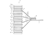
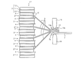
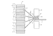
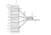
- FIG. 1a is a cross-sectional view taken along line AA of FIG. It is an enlarged plan view which shows the principal part of the positive electrode of the secondary battery shown in FIG. It is an enlarged plan view which shows the principal part of the negative electrode of the secondary battery shown in FIG. It is a side view which shows the connection process of an uncoated part and an electrode terminal of the manufacturing method of the electrochemical device of this invention. It is a side view which shows the process following FIG. 4 of the manufacturing method of the electrochemical device of this invention. It is a side view which shows the process following FIG. 5 of the manufacturing method of the electrochemical device of this invention. It is a side view which shows the process following FIG. 6 of the manufacturing method of the electrochemical device of this invention.
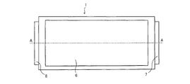
- FIG. 1a is a plan view of the secondary battery as viewed from vertically above the main surface (flat surface).
- 1b is a cross-sectional view taken along line AA of FIG. 1a.
- FIG. 2 is an enlarged cross-sectional view of the main part of the positive electrode.
- the lithium ion secondary battery 1 of the present invention includes a storage element (electrode assembly) 17 in which a positive electrode (positive electrode sheet) 2 and a negative electrode (negative electrode sheet) 3 overlap with a separator 4 interposed therebetween.
- the electrode assembly 17 is housed in an exterior container made of the flexible film 6 together with the electrolytic solution 5.
- One end of the positive electrode terminal 7 is connected to the positive electrode 2 of the electrode assembly 17, and one end of the negative electrode terminal 8 is connected to the negative electrode 3.
- the other end side of the positive electrode terminal 7 and the other end side of the negative electrode terminal 8 are each drawn out of the flexible film 6.
- the electrolyte solution 5 is shown by omitting a part of each layer constituting the electrode assembly 17 (a layer located in an intermediate portion in the thickness direction).
- the positive electrode 2, the negative electrode 3, and the separator 4 are illustrated so as not to be in contact with each other.
- the positive electrode 2 includes a positive electrode current collector (positive electrode current collector) 9, and a positive electrode active material layer (positive electrode active material layer) 10 applied to the positive electrode current collector 9. including. On the front and back surfaces of the positive electrode current collector 9, an application part where the positive electrode active material layer 10 is formed and an unapplied part where the positive electrode active material layer 10 is not formed are located side by side along the longitudinal direction. .
- the negative electrode 3 includes a negative electrode current collector (negative electrode current collector) 11, and a negative electrode active material layer (negative electrode active material layer) 12 applied to the negative electrode current collector 11. including. On the front and back surfaces of the negative electrode current collector 11, the coated portion and the uncoated portion are positioned side by side along the longitudinal direction.
- Each uncoated part (current collector) of the positive electrode 2 and the negative electrode 3 is used as a tab for connecting to an electrode terminal (positive electrode terminal 7 or negative electrode terminal 8).
- the positive electrode tabs (uncoated portions) of the positive electrode 2 are gathered on the positive electrode terminal 7 and are connected to each other by ultrasonic welding or the like while being sandwiched between the metal piece (support tab) 13 and the positive electrode terminal 7.
- the negative electrode tabs (uncoated portions) of the negative electrode 3 are gathered on the negative electrode terminal 8 and are connected to each other by ultrasonic welding or the like while being sandwiched between the metal piece (support tab) 13 and the negative electrode terminal 8. These joints are covered with an insulating tape 14.
- the other end portion of the positive electrode terminal 7 and the other end portion of the negative electrode terminal 8 are drawn out of the exterior container made of the flexible film 6, respectively.
- the outer dimension of the coating part (negative electrode active material layer 12) of the negative electrode 3 is larger than the outer dimension of the coating part (positive electrode active material layer 10) of the positive electrode 2 and smaller than or equal to the outer dimension of the separator 4.
- examples of the active material constituting the positive electrode active material layer 10 include LiCoO 2 , LiNiO 2 , LiMn 2 O 2 , Li 2 MO 3 -LiMO 2 , LiNi 1/3 Co 1/3.
- Layered oxide materials such as Mn 1/3 O 2 , spinel materials such as LiMn 2 O 4 , olivine materials such as LiMPO 4 , fluoride olivine materials such as Li 2 MPO 4 F and Li 2 MSiO 4 F
- examples thereof include vanadium oxide materials such as materials and V 2 O 5 .
- a part of elements constituting these active materials may be substituted with other elements, and Li may have an excessive composition.
- One or a mixture of two or more of these active materials can be used.
- carbon materials such as graphite, amorphous carbon, diamond-like carbon, fullerene, carbon nanotube, and carbon nanohorn, lithium metal materials, alloy materials such as silicon and tin, An oxide material such as Nb 2 O 5 or TiO 2 or a composite thereof can be used.
- the active material mixture constituting the positive electrode active material layer 10 and the negative electrode active material layer 12 is obtained by appropriately adding a binder, a conductive auxiliary agent or the like to each of the active materials described above.
- a conductive support agent 1 type in carbon black, carbon fiber, or graphite can be used, or a combination of 2 or more types can be used.
- the binder polyvinylidene fluoride, polytetrafluoroethylene, carboxymethylcellulose, modified acrylonitrile rubber particles, and the like can be used.
- the positive electrode current collector 9 aluminum, stainless steel, nickel, titanium, or an alloy thereof can be used, and aluminum is particularly preferable.
- the negative electrode current collector 11 copper, stainless steel, nickel, titanium, or an alloy thereof can be used.
- Examples of the electrolytic solution 5 include cyclic carbonates such as ethylene carbonate, propylene carbonate, vinylene carbonate, butylene carbonate, ethyl methyl carbonate (EMC), diethyl carbonate (DEC), dimethyl carbonate (DMC), dipropyl carbonate (DPC), and the like.
- cyclic carbonates such as ethylene carbonate, propylene carbonate, vinylene carbonate, butylene carbonate, ethyl methyl carbonate (EMC), diethyl carbonate (DEC), dimethyl carbonate (DMC), dipropyl carbonate (DPC), and the like.
- One or more organic solvents such as chain carbonates, aliphatic carboxylic acid esters, ⁇ -lactones such as ⁇ -butyrolactone, chain ethers, cyclic ethers, etc. Mixtures can be used.
- lithium salts can be dissolved in these organic solvents.
- the separator 4 is mainly composed of a resin porous film, woven fabric, non-woven fabric, etc., and as its resin component, for example, polyolefin resin such as polypropylene and polyethylene, polyester resin, acrylic resin, styrene resin, nylon resin, aramid resin (aromatic resin) Polyamide resin), polyimide resin, or the like can be used.
- a polyolefin-based microporous membrane is preferable because of its excellent ion permeability and performance of physically separating the positive electrode and the negative electrode.
- the inorganic particles include insulating oxides, nitrides, sulfides, carbides, etc. Among them, it is preferable that TiO 2 or Al 2 O 3 is included.
- a lightweight exterior case made of the flexible film 6 is used.
- the flexible film 6 a laminate film in which a resin layer is provided on each of the front surface and the back surface of a metal layer serving as a base material can be used.
- a metal layer having barrier properties such as leakage of the electrolytic solution 5 and prevention of moisture from the outside can be selected, and aluminum, stainless steel, or the like can be used.
- a heat-fusible resin layer such as a modified polyolefin is provided.
- the heat-sealing resin layers of the flexible film 6 are opposed to each other, and the periphery of the portion that houses the electrode assembly 17 is heat-sealed to form an outer container.
- a resin layer such as a nylon film, a polyethylene terephthalate film, or a polyester film can be provided on the surface of the exterior body that is the surface opposite to the surface on which the heat-fusible resin layer is formed.
- each terminal 7 and 8 is pulled out of the exterior container.
- a heat-sealable resin can be provided in advance at locations corresponding to the portions of the terminals 7 and 8 that are thermally welded to the outer peripheral portion of the outer container.
- any of the positive electrode active material layer 10 and the negative electrode active material layer 12 for example, inevitable inclination, unevenness, roundness, etc. of each layer due to manufacturing variations and layer forming ability may occur.
- the electrodes 2 and 3 for the secondary battery are manufactured.
- the positive electrode active material layers 10 are respectively formed on both surfaces of the positive electrode current collector 9.
- the end of the coated part (positive electrode active material layer 10) at the boundary with the uncoated part may be substantially perpendicular to the positive electrode current collector 9, and the center of the positive electrode active material layer 10 may be You may have the edge part from which thickness differs compared with a part.
- negative electrode active material layers 12 are formed on both surfaces of the negative electrode current collector 11, respectively.
- the end portion of the negative electrode active material layer 12 may stand substantially perpendicular to the negative electrode current collector 11 and is thicker than the central portion of the negative electrode active material layer 12. You may have the edge part from which thickness differs.
- the positive electrode 2 and the negative electrode 3 thus formed are alternately stacked via the separator 4, and the positive electrode terminal 7 and the negative electrode terminal 8 are connected.
- connection process of the positive terminal 7 and the negative terminal 8 will be described in detail.
- the uncoated portions (positive electrode current collector 9) of the plurality of positive electrodes 2 are closely overlapped on the positive electrode terminal 7, and a metal piece (support tab) 13 is further stacked thereon. Arrange. Then, as shown in FIG. 5, ultrasonic welding is performed by applying vibration while pressing the horn 15 and the anvil 19 against the positive electrode terminal 7 and the metal piece 13 sandwiching the plurality of positive electrode current collectors 9.
- the metal piece 13 the plurality of uncoated portions (positive electrode current collector 9) and the positive electrode terminal 7 are joined, the periphery of the contact portion of the metal piece 13 and the positive electrode terminal 7 with the horn 15 and the anvil 19 is lifted.
- pressing is performed by the pressing member 16 so as to press the raised portions 7a and 13a.
- the metal piece 13 and the positive electrode terminal 7 are re-deformed so as to be flat.
- a protective insulating tape 14 is stuck on the metal piece 13.
- an aggregated portion in which a plurality of uncoated portions (negative electrode current collectors) 11 are overlapped is sandwiched between the metal piece 13 and the negative electrode terminal 8 and is ultrasonically welded.
- the metal piece 13 and the negative electrode terminal 8 are deformed so that particularly the edge portion is lifted, and therefore, pressing is performed using the pressing member 16 to re-deform the joint portion so as to be flat. Then, a protective insulating tape 14 is attached on the metal piece 13.
- the positive electrode terminal 7 is connected to the gathered portion of the uncoated portion (positive electrode current collector 9) of the positive electrode 2, and the negative electrode terminal 8 is joined to the gathered portion of the uncoated portion (negative electrode current collector 11) of the negative electrode 3.
- the connected electrode assembly 17 is housed in an exterior container made of the flexible film 6 together with the electrolytic solution 5.
- the positive electrode terminal 7 and the negative electrode terminal 8 led out to the outside of the outer container are fixed to the outer peripheral portion of the flexible film 6 through a sealing material (sealant) 18 provided in advance on each electrode terminal 7, 8.
- the outer container containing the electrode assembly 17 is sealed by thermally welding the outer peripheral parts of the flexible film 6,
- the secondary battery 1 shown in FIG. 1 is completed.
- the metal piece 13 and a part 7 a of the electrode terminals 7, 8. , 13a is lifted so that the metal piece 13 and the electrode terminals 7 and 8 are flattened by pressing using the pressing member 16, and then the electrode assembly 17 is made of the flexible film 6. Housed inside. Therefore, the flexible film 6 can be prevented from being damaged by the raised portions 7a and 13a of the metal piece 13 and the electrode terminals 7 and 8. Moreover, even if burrs, burrs, and the like are generated during the formation of the metal piece 13 and the electrode terminals 7 and 8, they can be flattened by pressing.
- the metal piece 13 and the electrode terminals 7 and 8 cannot be strictly flattened, it is sufficient if a sharp projecting portion that damages the flexible film 6 can be eliminated by pressing. It is effective.
- the raised portions 7a and 13a of the metal piece 13 and the electrode terminals 7 and 8 may be pressed by the pressing member 16 to generate a portion where the edge is crushed and raised slightly, or a portion where the edge is folded back.
- it is effective as the present invention because it has an effect of suppressing damage to the flexible film 6 due to deformation of at least the electrode terminals 7 and 8.
- the present invention it is possible to prevent the outer container from being damaged from the inside due to deformation (raising of the edge) that occurs when joining at least the electrode terminals 7 and 8 and the uncoated portions (current collectors 9 and 11). Can do. This suppresses the short circuit between the inner metal layer of the exterior film and the electrode and the accompanying alloy formation, reducing the performance of the battery and the risk of leakage of the fluid (electrolyte 5) from the exterior container. can do.
- a stacked body in which a plurality of positive electrodes 2 and a plurality of negative electrodes 3 are alternately and repeatedly stacked via separators 4 is used as the electrode assembly 17.
- a laminated body in which only one positive electrode 2 and only one negative electrode 3 overlap with each other through the separator 4 can also be used as the electrode assembly 17.
- a wound body obtained by winding a single long positive electrode 2 and a single long negative electrode 3 with a separator 4 interposed therebetween may be used as the electrode assembly 17.
- the present invention is particularly useful for a method for producing a lithium ion secondary battery, but may be applied to a method for producing a secondary battery other than a lithium ion battery or an electrochemical device other than a battery such as a capacitor (capacitor). It is valid.
- Lithium ion secondary battery (electrochemical device) 2 Positive electrode (positive electrode sheet) 3 Negative electrode (negative electrode sheet) 4 Separator 5 Electrolyte 6 Flexible film 7 Positive electrode terminal (electrode terminal) 7a, 13a The raised part 8 Negative terminal (electrode terminal) 9 Current collector for positive electrode (positive electrode current collector) 10 Active material layer for positive electrode (positive electrode active material layer) 11 Current collector for negative electrode (negative electrode current collector) 12 Active material layer for negative electrode (negative electrode active material layer) 13 Metal piece (support tab) 14 Insulating tape 15 Horn 16 Pressing member 17 Power storage element (electrode assembly) 18 Sealant 19 Anvil
Landscapes
- Chemical & Material Sciences (AREA)
- Chemical Kinetics & Catalysis (AREA)
- Electrochemistry (AREA)
- General Chemical & Material Sciences (AREA)
- Engineering & Computer Science (AREA)
- Power Engineering (AREA)
- Microelectronics & Electronic Packaging (AREA)
- Manufacturing & Machinery (AREA)
- Inorganic Chemistry (AREA)
- Connection Of Batteries Or Terminals (AREA)
- Secondary Cells (AREA)
- Electric Double-Layer Capacitors Or The Like (AREA)
- Sealing Battery Cases Or Jackets (AREA)
Abstract
Description
[二次電池の構成]
図1a,1bは、本発明の製造方法によって製造される電気化学デバイスの一例である積層型のリチウムイオン二次電池の構成の一例を模式的に示している。図1aは二次電池の主面(扁平な面)に対して垂直上方から見た平面図である。図1bは図1aのA-A線断面図である。図2は正極の要部の拡大断面図である。
二次電池の製造にあたって、まず二次電池用の電極2,3を製造する。具体的には、図2に示すように、正極集電体9の両面に正極活物質層10をそれぞれ形成する。未塗布部との境界部分における塗布部(正極活物質層10)の端部は、正極集電体9に対して実質的に垂直に切り立っていてもよく、また、正極活物質層10の中央部と比べて厚さの異なる端部を有していてもよい。また、図3に示すように、負極集電体11の両面に負極活物質層12をそれぞれ形成する。負極活物質層12の端部(塗布部の端部)は、負極集電体11に対して実質的に垂直に切り立っていてもよく、また、負極活物質層12の中央部と比べて厚さの異なる端部を有していてもよい。このようにして形成された正極2と負極3とを、セパレータ4を介して交互に積層し、正極端子7および負極端子8を接続する。
2 正極(正極シート)
3 負極(負極シート)
4 セパレータ
5 電解液
6 可撓性フィルム
7 正極端子(電極端子)
7a,13a 浮き上がった部分
8 負極端子(電極端子)
9 正極用の集電体(正極集電体)
10 正極用の活物質層(正極活物質層)
11 負極用の集電体(負極集電体)
12 負極用の活物質層(負極活物質層)
13 金属片(サポートタブ)
14 絶縁テープ
15 ホーン
16 押圧部材
17 蓄電要素(電極集合体)
18 封止材(シーラント)
19 アンビル
Claims (6)
- 2種類の電極がセパレータを介して重なり合う電極集合体が外装容器内に収容されており、前記2種類の電極はいずれも、集電体上に活物質層が形成された塗布部と、前記活物質層が形成されていない未塗布部とを有する、電気化学デバイスの製造方法であって、
前記2種類の電極を種類ごとにそれぞれ重ねてなる前記未塗布部の集合部と電極端子とを重ね合わせて接合する工程と、
前記接合する工程の後に、前記未塗布部の集合部と前記電極端子との接合部をプレスする工程と、
前記プレスする工程の後に、前記電極集合体を、可撓性フィルムからなる外装容器に収容する工程と、
を含む電気化学デバイスの製造方法。 - 前記接合する工程では、前記未塗布部の集合部の一面に前記電極端子を、他面に金属片をそれぞれ配し、前記未塗布部の集合部と一緒に重ね合わせて接合し、前記プレスする工程では、前記未塗布部の集合部を挟んでいる前記電極端子と前記金属片とをそれぞれ押圧する、請求項1に記載の電気化学デバイス用の電極の製造方法。
- 前記プレスする工程では、押圧部材によって前記金属片の少なくともエッジ部分を押圧する、請求項2に記載の電気化学デバイスの製造方法。
- 前記プレスする工程の後に、前記金属片の上に絶縁テープを貼り付ける工程をさらに含む、請求項2または3に記載の電気化学デバイスの製造方法。
- 前記接合する工程では超音波溶接を行う、請求項1から4のいずれか1項に記載の電気化学デバイスの製造方法。
- 前記電気化学デバイスは二次電池である、請求項1から5のいずれか1項に記載の電気化学デバイスの製造方法。
Priority Applications (4)
| Application Number | Priority Date | Filing Date | Title |
|---|---|---|---|
| JP2017524669A JP6757318B2 (ja) | 2015-06-25 | 2016-03-18 | 電気化学デバイスの製造方法 |
| EP16814009.3A EP3316349B1 (en) | 2015-06-25 | 2016-03-18 | Method for manufacturing electrochemical device |
| CN201680038207.5A CN107851768B (zh) | 2015-06-25 | 2016-03-18 | 电化学器件的制造方法 |
| US15/576,323 US20180158623A1 (en) | 2015-06-25 | 2016-03-18 | Method for manufacturing electrochemical device |
Applications Claiming Priority (2)
| Application Number | Priority Date | Filing Date | Title |
|---|---|---|---|
| JP2015127722 | 2015-06-25 | ||
| JP2015-127722 | 2015-06-25 |
Publications (1)
| Publication Number | Publication Date |
|---|---|
| WO2016208238A1 true WO2016208238A1 (ja) | 2016-12-29 |
Family
ID=57585502
Family Applications (1)
| Application Number | Title | Priority Date | Filing Date |
|---|---|---|---|
| PCT/JP2016/058831 Ceased WO2016208238A1 (ja) | 2015-06-25 | 2016-03-18 | 電気化学デバイスの製造方法 |
Country Status (5)
| Country | Link |
|---|---|
| US (1) | US20180158623A1 (ja) |
| EP (1) | EP3316349B1 (ja) |
| JP (1) | JP6757318B2 (ja) |
| CN (1) | CN107851768B (ja) |
| WO (1) | WO2016208238A1 (ja) |
Cited By (6)
| Publication number | Priority date | Publication date | Assignee | Title |
|---|---|---|---|---|
| WO2018155035A1 (ja) * | 2017-02-22 | 2018-08-30 | Necエナジーデバイス株式会社 | リチウムイオン電池 |
| JP2020119875A (ja) * | 2019-01-29 | 2020-08-06 | 三洋電機株式会社 | 二次電池及びその製造方法 |
| JP2020119874A (ja) * | 2019-01-29 | 2020-08-06 | 三洋電機株式会社 | 二次電池及びその製造方法 |
| KR20200124170A (ko) | 2019-04-23 | 2020-11-02 | 도요타 지도샤(주) | 이차 전지의 제조 방법 및 이차 전지 |
| JP2021016878A (ja) * | 2019-07-19 | 2021-02-15 | トヨタ自動車株式会社 | 超音波接合方法 |
| JP2024523249A (ja) * | 2021-12-27 | 2024-06-28 | エルジー エナジー ソリューション リミテッド | 電極タブと電極リードの接合部圧着装置 |
Families Citing this family (4)
| Publication number | Priority date | Publication date | Assignee | Title |
|---|---|---|---|---|
| JP7061971B2 (ja) | 2016-05-20 | 2022-05-02 | キョーセラ・エイブイエックス・コンポーネンツ・コーポレーション | マルチセル・ウルトラキャパシタ |
| US11830672B2 (en) | 2016-11-23 | 2023-11-28 | KYOCERA AVX Components Corporation | Ultracapacitor for use in a solder reflow process |
| JP7316520B2 (ja) * | 2018-12-10 | 2023-07-28 | トヨタ自動車株式会社 | 電池 |
| KR102820000B1 (ko) * | 2020-10-16 | 2025-06-12 | 주식회사 엘지에너지솔루션 | 노칭 파일럿 핀을 구비한 전극 성형 장치 및 이를 이용하여 전극을 성형하는 방법 |
Citations (8)
| Publication number | Priority date | Publication date | Assignee | Title |
|---|---|---|---|---|
| JPH10223216A (ja) * | 1997-02-10 | 1998-08-21 | Matsushita Electric Ind Co Ltd | 電池用電極の製造法 |
| JP2001236947A (ja) * | 2000-02-23 | 2001-08-31 | Sony Corp | 電極及び電池、並びにそれらの製造方法 |
| JP2001321953A (ja) * | 2000-05-15 | 2001-11-20 | Daihatsu Motor Co Ltd | スポット溶接方法およびスポット溶接装置 |
| JP2005149938A (ja) * | 2003-11-17 | 2005-06-09 | Nec Lamilion Energy Ltd | フィルム外装電池およびフィルム外装電池の製造方法 |
| JP2007130685A (ja) * | 2005-11-14 | 2007-05-31 | Nippon Steel Corp | 高強度鋼板スポット溶接継手の疲労強度向上方法 |
| JP2007305345A (ja) * | 2006-05-09 | 2007-11-22 | Panasonic Ev Energy Co Ltd | 電池用正極及びその製造方法、並びに電池 |
| JP2011204552A (ja) * | 2010-03-26 | 2011-10-13 | Mitsubishi Heavy Ind Ltd | 電池、及びこの電池の製造に用いられる超音波溶接システム |
| JP2014191967A (ja) * | 2013-03-27 | 2014-10-06 | Murata Mfg Co Ltd | 電池 |
Family Cites Families (9)
| Publication number | Priority date | Publication date | Assignee | Title |
|---|---|---|---|---|
| JPH09199117A (ja) * | 1996-01-12 | 1997-07-31 | Furukawa Battery Co Ltd:The | 正極板およびその製造方法 |
| DE10147565A1 (de) * | 2001-09-26 | 2003-04-10 | Varta Microbattery Gmbh | Vorrichtung zum gas- und flüssigkeitsdichten Versiegeln der Gehäuse von galvanischen Elementen |
| JP5676172B2 (ja) * | 2010-08-03 | 2015-02-25 | Necエナジーデバイス株式会社 | ラミネートフィルム外装積層型電池の製造方法 |
| JP5891655B2 (ja) * | 2010-08-30 | 2016-03-23 | ソニー株式会社 | 非水電解質電池および非水電解質電池の製造方法、並びに絶縁材および絶縁材の製造方法、並びに電池パック、電子機器、電動車両、蓄電装置および電力システム |
| JP5844052B2 (ja) * | 2011-02-04 | 2016-01-13 | 三洋電機株式会社 | 積層式電池およびその製造方法 |
| WO2013105362A1 (ja) * | 2012-01-12 | 2013-07-18 | 日立マクセル株式会社 | 電池の製造方法 |
| US20150244017A1 (en) * | 2012-08-29 | 2015-08-27 | Sharp Kabushiki Kaisha | Electrode plate and secondary battery |
| JP2014167881A (ja) * | 2013-02-28 | 2014-09-11 | Sanyo Electric Co Ltd | 電池及び電池の製造方法 |
| DE102014217162A1 (de) * | 2014-08-28 | 2016-03-03 | Robert Bosch Gmbh | Ultraschallschweißanlage mit Absaugung |
-
2016
- 2016-03-18 JP JP2017524669A patent/JP6757318B2/ja active Active
- 2016-03-18 EP EP16814009.3A patent/EP3316349B1/en active Active
- 2016-03-18 CN CN201680038207.5A patent/CN107851768B/zh active Active
- 2016-03-18 US US15/576,323 patent/US20180158623A1/en not_active Abandoned
- 2016-03-18 WO PCT/JP2016/058831 patent/WO2016208238A1/ja not_active Ceased
Patent Citations (8)
| Publication number | Priority date | Publication date | Assignee | Title |
|---|---|---|---|---|
| JPH10223216A (ja) * | 1997-02-10 | 1998-08-21 | Matsushita Electric Ind Co Ltd | 電池用電極の製造法 |
| JP2001236947A (ja) * | 2000-02-23 | 2001-08-31 | Sony Corp | 電極及び電池、並びにそれらの製造方法 |
| JP2001321953A (ja) * | 2000-05-15 | 2001-11-20 | Daihatsu Motor Co Ltd | スポット溶接方法およびスポット溶接装置 |
| JP2005149938A (ja) * | 2003-11-17 | 2005-06-09 | Nec Lamilion Energy Ltd | フィルム外装電池およびフィルム外装電池の製造方法 |
| JP2007130685A (ja) * | 2005-11-14 | 2007-05-31 | Nippon Steel Corp | 高強度鋼板スポット溶接継手の疲労強度向上方法 |
| JP2007305345A (ja) * | 2006-05-09 | 2007-11-22 | Panasonic Ev Energy Co Ltd | 電池用正極及びその製造方法、並びに電池 |
| JP2011204552A (ja) * | 2010-03-26 | 2011-10-13 | Mitsubishi Heavy Ind Ltd | 電池、及びこの電池の製造に用いられる超音波溶接システム |
| JP2014191967A (ja) * | 2013-03-27 | 2014-10-06 | Murata Mfg Co Ltd | 電池 |
Non-Patent Citations (1)
| Title |
|---|
| See also references of EP3316349A4 * |
Cited By (16)
| Publication number | Priority date | Publication date | Assignee | Title |
|---|---|---|---|---|
| CN110291661B (zh) * | 2017-02-22 | 2022-06-17 | 远景Aesc日本有限公司 | 锂离子电池 |
| CN110291661A (zh) * | 2017-02-22 | 2019-09-27 | 远景Aesc能源元器件有限公司 | 锂离子电池 |
| JPWO2018155035A1 (ja) * | 2017-02-22 | 2019-12-12 | 株式会社エンビジョンAescエナジーデバイス | リチウムイオン電池 |
| US12512504B2 (en) | 2017-02-22 | 2025-12-30 | Aesc Japan Ltd. | Lithium ion battery |
| WO2018155035A1 (ja) * | 2017-02-22 | 2018-08-30 | Necエナジーデバイス株式会社 | リチウムイオン電池 |
| JP2020119874A (ja) * | 2019-01-29 | 2020-08-06 | 三洋電機株式会社 | 二次電池及びその製造方法 |
| JP7229027B2 (ja) | 2019-01-29 | 2023-02-27 | 三洋電機株式会社 | 二次電池及びその製造方法 |
| JP2020119875A (ja) * | 2019-01-29 | 2020-08-06 | 三洋電機株式会社 | 二次電池及びその製造方法 |
| JP2020181635A (ja) * | 2019-04-23 | 2020-11-05 | トヨタ自動車株式会社 | 二次電池の製造方法および二次電池 |
| KR20200124170A (ko) | 2019-04-23 | 2020-11-02 | 도요타 지도샤(주) | 이차 전지의 제조 방법 및 이차 전지 |
| JP7194335B2 (ja) | 2019-04-23 | 2022-12-22 | トヨタ自動車株式会社 | 二次電池の製造方法および二次電池 |
| US11724333B2 (en) | 2019-04-23 | 2023-08-15 | Toyota Jidosha Kabushiki Kaisha | Manufacturing method of secondary battery and secondary battery |
| JP2021016878A (ja) * | 2019-07-19 | 2021-02-15 | トヨタ自動車株式会社 | 超音波接合方法 |
| JP7205723B2 (ja) | 2019-07-19 | 2023-01-17 | トヨタ自動車株式会社 | 超音波接合方法 |
| JP2024523249A (ja) * | 2021-12-27 | 2024-06-28 | エルジー エナジー ソリューション リミテッド | 電極タブと電極リードの接合部圧着装置 |
| JP7626350B2 (ja) | 2021-12-27 | 2025-02-04 | エルジー エナジー ソリューション リミテッド | 電極タブと電極リードの接合部圧着装置 |
Also Published As
| Publication number | Publication date |
|---|---|
| JP6757318B2 (ja) | 2020-09-16 |
| CN107851768A (zh) | 2018-03-27 |
| JPWO2016208238A1 (ja) | 2018-04-12 |
| EP3316349B1 (en) | 2022-02-23 |
| US20180158623A1 (en) | 2018-06-07 |
| EP3316349A4 (en) | 2018-12-26 |
| EP3316349A1 (en) | 2018-05-02 |
| CN107851768B (zh) | 2021-06-25 |
Similar Documents
| Publication | Publication Date | Title |
|---|---|---|
| JP6757318B2 (ja) | 電気化学デバイスの製造方法 | |
| JP6735445B2 (ja) | 捲回型電池 | |
| JP6779905B2 (ja) | 電気化学デバイス | |
| JP6504158B2 (ja) | 積層型電池及びその製造方法 | |
| CN103682232B (zh) | 电池 | |
| US20120202105A1 (en) | Stack type battery and method of manufacturing the same | |
| WO2015129320A1 (ja) | 二次電池用電極および二次電池とそれらの製造方法 | |
| WO2015015663A1 (ja) | 二次電池 | |
| JP2017069207A (ja) | リチウムイオン二次電池及びその製造方法 | |
| WO2018079817A1 (ja) | 電気化学デバイス用の電極と、電気化学デバイスと、それらの製造方法 | |
| JP2015199095A (ja) | 超音波溶接装置、及び電池の製造方法 | |
| WO2017033514A1 (ja) | 電気化学デバイス | |
| JP2013145678A (ja) | 非水電解質二次電池 | |
| WO2014141640A1 (ja) | ラミネート外装電池 | |
| JP6619594B2 (ja) | リチウムイオン二次電池及びその製造方法 | |
| WO2017098995A1 (ja) | 電気化学デバイスとその製造方法 | |
| JP2019102167A (ja) | 電気化学デバイス | |
| JP7231323B2 (ja) | 電気化学デバイス | |
| JP5334109B2 (ja) | ラミネート形電池 | |
| JP7109233B2 (ja) | 電気化学デバイスの製造方法 | |
| WO2013105362A1 (ja) | 電池の製造方法 | |
| JP2007087652A (ja) | 非水電解質電池 | |
| WO2017057691A1 (ja) | 電気化学デバイスとその製造方法 | |
| JP2018056030A (ja) | 非水電解質二次電池 |
Legal Events
| Date | Code | Title | Description |
|---|---|---|---|
| 121 | Ep: the epo has been informed by wipo that ep was designated in this application |
Ref document number: 16814009 Country of ref document: EP Kind code of ref document: A1 |
|
| WWE | Wipo information: entry into national phase |
Ref document number: 15576323 Country of ref document: US |
|
| ENP | Entry into the national phase |
Ref document number: 2017524669 Country of ref document: JP Kind code of ref document: A |
|
| NENP | Non-entry into the national phase |
Ref country code: DE |
|
| WWE | Wipo information: entry into national phase |
Ref document number: 2016814009 Country of ref document: EP |