WO2016208400A1 - エネルギーマネジメントシステム - Google Patents
エネルギーマネジメントシステム Download PDFInfo
- Publication number
- WO2016208400A1 WO2016208400A1 PCT/JP2016/067161 JP2016067161W WO2016208400A1 WO 2016208400 A1 WO2016208400 A1 WO 2016208400A1 JP 2016067161 W JP2016067161 W JP 2016067161W WO 2016208400 A1 WO2016208400 A1 WO 2016208400A1
- Authority
- WO
- WIPO (PCT)
- Prior art keywords
- voltage
- converter
- unit
- calibration
- bus
- Prior art date
- Legal status (The legal status is an assumption and is not a legal conclusion. Google has not performed a legal analysis and makes no representation as to the accuracy of the status listed.)
- Ceased
Links
Images



Classifications
-
- H—ELECTRICITY
- H02—GENERATION; CONVERSION OR DISTRIBUTION OF ELECTRIC POWER
- H02J—ELECTRIC POWER NETWORKS; CIRCUIT ARRANGEMENTS OR SYSTEMS FOR SUPPLYING OR DISTRIBUTING ELECTRIC POWER; SYSTEMS FOR STORING ELECTRIC ENERGY
- H02J7/00—Circuit arrangements for charging or discharging batteries or for supplying loads from batteries
- H02J7/34—Parallel operation in networks using both storage and other DC sources, e.g. providing buffering
- H02J7/35—Parallel operation in networks using both storage and other DC sources, e.g. providing buffering with light sensitive cells
-
- H—ELECTRICITY
- H02—GENERATION; CONVERSION OR DISTRIBUTION OF ELECTRIC POWER
- H02J—ELECTRIC POWER NETWORKS; CIRCUIT ARRANGEMENTS OR SYSTEMS FOR SUPPLYING OR DISTRIBUTING ELECTRIC POWER; SYSTEMS FOR STORING ELECTRIC ENERGY
- H02J1/00—Circuit arrangements for DC mains or DC distribution networks
- H02J1/10—Parallel operation of DC sources
- H02J1/102—Parallel operation of DC sources being switching converters
-
- H—ELECTRICITY
- H02—GENERATION; CONVERSION OR DISTRIBUTION OF ELECTRIC POWER
- H02J—ELECTRIC POWER NETWORKS; CIRCUIT ARRANGEMENTS OR SYSTEMS FOR SUPPLYING OR DISTRIBUTING ELECTRIC POWER; SYSTEMS FOR STORING ELECTRIC ENERGY
- H02J1/00—Circuit arrangements for DC mains or DC distribution networks
- H02J1/10—Parallel operation of DC sources
- H02J1/12—Parallel operation of DC sources having power converters with further DC sources without power converters
-
- H—ELECTRICITY
- H02—GENERATION; CONVERSION OR DISTRIBUTION OF ELECTRIC POWER
- H02J—ELECTRIC POWER NETWORKS; CIRCUIT ARRANGEMENTS OR SYSTEMS FOR SUPPLYING OR DISTRIBUTING ELECTRIC POWER; SYSTEMS FOR STORING ELECTRIC ENERGY
- H02J3/00—Circuit arrangements for AC mains or AC distribution networks
- H02J3/38—Arrangements for feeding a single network from two or more generators or sources in parallel; Arrangements for feeding already energised networks from additional generators or sources in parallel
-
- H—ELECTRICITY
- H02—GENERATION; CONVERSION OR DISTRIBUTION OF ELECTRIC POWER
- H02J—ELECTRIC POWER NETWORKS; CIRCUIT ARRANGEMENTS OR SYSTEMS FOR SUPPLYING OR DISTRIBUTING ELECTRIC POWER; SYSTEMS FOR STORING ELECTRIC ENERGY
- H02J3/00—Circuit arrangements for AC mains or AC distribution networks
- H02J3/38—Arrangements for feeding a single network from two or more generators or sources in parallel; Arrangements for feeding already energised networks from additional generators or sources in parallel
- H02J3/381—Dispersed generators
-
- H—ELECTRICITY
- H02—GENERATION; CONVERSION OR DISTRIBUTION OF ELECTRIC POWER
- H02M—APPARATUS FOR CONVERSION BETWEEN AC AND AC, BETWEEN AC AND DC, OR BETWEEN DC AND DC, AND FOR USE WITH MAINS OR SIMILAR POWER SUPPLY SYSTEMS; CONVERSION OF DC OR AC INPUT POWER INTO SURGE OUTPUT POWER; CONTROL OR REGULATION THEREOF
- H02M3/00—Conversion of DC power input into DC power output
- H02M3/02—Conversion of DC power input into DC power output without intermediate conversion into AC
-
- H—ELECTRICITY
- H02—GENERATION; CONVERSION OR DISTRIBUTION OF ELECTRIC POWER
- H02M—APPARATUS FOR CONVERSION BETWEEN AC AND AC, BETWEEN AC AND DC, OR BETWEEN DC AND DC, AND FOR USE WITH MAINS OR SIMILAR POWER SUPPLY SYSTEMS; CONVERSION OF DC OR AC INPUT POWER INTO SURGE OUTPUT POWER; CONTROL OR REGULATION THEREOF
- H02M7/00—Conversion of AC power input into DC power output; Conversion of DC power input into AC power output
- H02M7/42—Conversion of DC power input into AC power output without possibility of reversal
- H02M7/44—Conversion of DC power input into AC power output without possibility of reversal by static converters
-
- H—ELECTRICITY
- H02—GENERATION; CONVERSION OR DISTRIBUTION OF ELECTRIC POWER
- H02M—APPARATUS FOR CONVERSION BETWEEN AC AND AC, BETWEEN AC AND DC, OR BETWEEN DC AND DC, AND FOR USE WITH MAINS OR SIMILAR POWER SUPPLY SYSTEMS; CONVERSION OF DC OR AC INPUT POWER INTO SURGE OUTPUT POWER; CONTROL OR REGULATION THEREOF
- H02M7/00—Conversion of AC power input into DC power output; Conversion of DC power input into AC power output
- H02M7/42—Conversion of DC power input into AC power output without possibility of reversal
- H02M7/44—Conversion of DC power input into AC power output without possibility of reversal by static converters
- H02M7/48—Conversion of DC power input into AC power output without possibility of reversal by static converters using discharge tubes with control electrode or semiconductor devices with control electrode
-
- H—ELECTRICITY
- H02—GENERATION; CONVERSION OR DISTRIBUTION OF ELECTRIC POWER
- H02J—ELECTRIC POWER NETWORKS; CIRCUIT ARRANGEMENTS OR SYSTEMS FOR SUPPLYING OR DISTRIBUTING ELECTRIC POWER; SYSTEMS FOR STORING ELECTRIC ENERGY
- H02J2101/00—Supply or distribution of decentralised, dispersed or local electric power generation
- H02J2101/20—Dispersed power generation using renewable energy sources
- H02J2101/22—Solar energy
- H02J2101/24—Photovoltaics
-
- H—ELECTRICITY
- H02—GENERATION; CONVERSION OR DISTRIBUTION OF ELECTRIC POWER
- H02J—ELECTRIC POWER NETWORKS; CIRCUIT ARRANGEMENTS OR SYSTEMS FOR SUPPLYING OR DISTRIBUTING ELECTRIC POWER; SYSTEMS FOR STORING ELECTRIC ENERGY
- H02J2105/00—Networks for supplying or distributing electric power characterised by their spatial reach or by the load
- H02J2105/10—Local stationary networks having a local or delimited stationary reach
- H02J2105/12—Local stationary networks having a local or delimited stationary reach supplying households or buildings
-
- H—ELECTRICITY
- H02—GENERATION; CONVERSION OR DISTRIBUTION OF ELECTRIC POWER
- H02J—ELECTRIC POWER NETWORKS; CIRCUIT ARRANGEMENTS OR SYSTEMS FOR SUPPLYING OR DISTRIBUTING ELECTRIC POWER; SYSTEMS FOR STORING ELECTRIC ENERGY
- H02J3/00—Circuit arrangements for AC mains or AC distribution networks
- H02J3/28—Arrangements for balancing of the load in networks by storage of energy
- H02J3/32—Arrangements for balancing of the load in networks by storage of energy using batteries or super capacitors with converting means
-
- Y—GENERAL TAGGING OF NEW TECHNOLOGICAL DEVELOPMENTS; GENERAL TAGGING OF CROSS-SECTIONAL TECHNOLOGIES SPANNING OVER SEVERAL SECTIONS OF THE IPC; TECHNICAL SUBJECTS COVERED BY FORMER USPC CROSS-REFERENCE ART COLLECTIONS [XRACs] AND DIGESTS
- Y02—TECHNOLOGIES OR APPLICATIONS FOR MITIGATION OR ADAPTATION AGAINST CLIMATE CHANGE
- Y02E—REDUCTION OF GREENHOUSE GAS [GHG] EMISSIONS, RELATED TO ENERGY GENERATION, TRANSMISSION OR DISTRIBUTION
- Y02E10/00—Energy generation through renewable energy sources
- Y02E10/50—Photovoltaic [PV] energy
- Y02E10/56—Power conversion systems, e.g. maximum power point trackers
-
- Y—GENERAL TAGGING OF NEW TECHNOLOGICAL DEVELOPMENTS; GENERAL TAGGING OF CROSS-SECTIONAL TECHNOLOGIES SPANNING OVER SEVERAL SECTIONS OF THE IPC; TECHNICAL SUBJECTS COVERED BY FORMER USPC CROSS-REFERENCE ART COLLECTIONS [XRACs] AND DIGESTS
- Y02—TECHNOLOGIES OR APPLICATIONS FOR MITIGATION OR ADAPTATION AGAINST CLIMATE CHANGE
- Y02E—REDUCTION OF GREENHOUSE GAS [GHG] EMISSIONS, RELATED TO ENERGY GENERATION, TRANSMISSION OR DISTRIBUTION
- Y02E70/00—Other energy conversion or management systems reducing GHG emissions
- Y02E70/30—Systems combining energy storage with energy generation of non-fossil origin
-
- Y—GENERAL TAGGING OF NEW TECHNOLOGICAL DEVELOPMENTS; GENERAL TAGGING OF CROSS-SECTIONAL TECHNOLOGIES SPANNING OVER SEVERAL SECTIONS OF THE IPC; TECHNICAL SUBJECTS COVERED BY FORMER USPC CROSS-REFERENCE ART COLLECTIONS [XRACs] AND DIGESTS
- Y02—TECHNOLOGIES OR APPLICATIONS FOR MITIGATION OR ADAPTATION AGAINST CLIMATE CHANGE
- Y02P—CLIMATE CHANGE MITIGATION TECHNOLOGIES IN THE PRODUCTION OR PROCESSING OF GOODS
- Y02P90/00—Enabling technologies with a potential contribution to greenhouse gas [GHG] emissions mitigation
- Y02P90/50—Energy storage in industry with an added climate change mitigation effect
Definitions
- the present invention relates to an energy management system that uses electric power generated in a house or a factory.
- a solar power generation system that uses electric power generated by a generator, such as a solar panel, in a house or the like includes a direct-current voltage bus (hereinafter referred to as an HVDC bus).
- a PV converter, an inverter, a bidirectional DC-DC converter, and the like are connected to the HVDC bus.
- the PV converter outputs the electric power generated by the solar power generation device to the HVDC bus at a predetermined voltage.
- a storage battery is connected to the bidirectional DC-DC converter, and a direct-current voltage exchanged between the storage battery and the HVDC bus is converted into a predetermined constant voltage.
- the inverter transmits the power generated by the generator or the power stored in the storage battery to the power system, and supplies the power from the power system to the HVDC bus.
- Patent Document 1 discloses a power supply system in which a plurality of power supply units are connected to a DC voltage bus and cooperative control is possible.
- a plurality of power supply units such as a photovoltaic power generation unit
- a photovoltaic power generation unit are connected to a DC voltage bus, and power is exchanged with the DC voltage bus based on the voltage of the DC voltage bus.
- the amount is determined autonomously.
- such a photovoltaic power generation system or the like includes a detection circuit for detecting the voltage of the HVDC bus in order to keep the voltage of the HVDC bus at a predetermined value, and the detection result is a predetermined value.
- the voltage is controlled by switching control or the like so as to be a voltage.
- each component such as a PV converter connected to the HVDC bus has a problem that the lifetime is shortened when a voltage higher than a desired voltage value (for example, 380 V) is continuously applied. Therefore, it is desirable that the voltage of the DC voltage bus is set to be maintained at a lower voltage value as close as possible to the desired voltage value.
- a desired voltage value for example, 380 V
- the object of the present invention is to take measures to stabilize the voltage of the DC voltage bus even if deviation occurs in the voltage detection results by the plurality of voltage detection units as time passes, and
- the object is to provide an energy management system capable of extending the life of parts.
- the energy management system includes a DC voltage bus, a power generator connected to the DC voltage bus and outputting generated power to the DC voltage bus, the DC voltage bus, and the DC voltage bus.
- a DC voltage is input from the DC voltage converter, or a bidirectional DC-DC converter that outputs a DC voltage to the DC voltage bus, and a DC voltage that is connected to the DC voltage bus and input from the DC voltage bus is converted into an AC voltage.
- Each of the power generation device, the bidirectional DC-DC converter, and the inverter includes a voltage detection unit that detects a voltage of the DC voltage bus, and a voltage detected by the voltage detection unit is a target value.
- Switching control means for performing switching control so as to match, and compares the voltages detected by the respective voltage detectors
- a calibration value setting means for setting the highest voltage as a calibration value; and a calibration means for calibrating a detection voltage of a voltage detection unit other than the voltage detection unit detecting the highest voltage with the calibration value.
- each different detection result in the power generator, bidirectional DC-DC converter, and inverter will not match due to errors that occur over time.
- each different detection result is calibrated so as to have the highest voltage among the detection results.
- each of the power generation device, the bidirectional DC-DC converter, and the inverter is subjected to switching control using the calibrated voltage value.
- the voltage of the DC voltage bus can be stabilized even if the voltage detection results by the plurality of voltage detection units are shifted with time.
- each component in the power generator, bidirectional DC-DC converter and inverter will be The applied voltage can be reduced. Thereby, it becomes possible to lengthen the lifetime of components.
- the energy management system may include a controller area network, and the power generation device, the bidirectional DC-DC converter, and the inverter may be connected to the controller area network.
- This configuration eliminates the need for master / slave settings and enables mutual communication with noise-resistant serial bus communication.
- the energy management system includes a setting unit that sets a timing at which the voltage fluctuation of the DC voltage bus is minimized during a predetermined period, and the calibration unit calibrates at a timing set by the setting unit. But you can.
- the energy management system may include a temperature detection unit that detects an ambient temperature, and a correction unit that corrects the detection voltage by the voltage detection unit according to the temperature detected by the temperature detection unit. .
- the power generation device, the bidirectional DC-DC converter, and the inverter may each include the temperature detection means.
- the present invention it is possible to take measures to stabilize the voltage of the DC voltage bus to a predetermined value even if the voltage detection result is shifted with time, and to prolong the life of the parts. Can provide an energy management system.
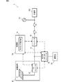
- FIG. 1 is a diagram illustrating an energy management system according to an embodiment.
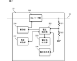
- FIG. 2 is a diagram illustrating a configuration of a PV converter included in the power generation device.
- FIG. 3 is a diagram showing the configuration of the bidirectional DC-DC converter.
- FIG. 4 is a diagram illustrating a configuration of the inverter.
- FIG. 5 is a diagram for explaining detection bus voltage calibration control.
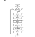
- FIG. 6 is a flowchart showing the operation of the bidirectional DC-DC converter.
- FIG. 7 is a flowchart showing the operation of the PV converter and the inverter.
- FIG. 1 is a diagram showing an energy management system 1 according to the present embodiment.
- the energy management system 1 includes a power generator 20, a bidirectional DC-DC converter 30, an inverter 40, and a control unit 50.
- the power generator 20, the bidirectional DC-DC converter 30, and the inverter 40 are connected to the HVDC bus 10.
- the HVDC bus 10 is an example of a “DC voltage bus” according to the present invention.
- the power generator 20, the bidirectional DC-DC converter 30, and the inverter 40 are connected to each other by a controller area network (CAN) so that data communication can be performed.
- CAN controller area network
- the power generation device 20 includes a photovoltaic panel 21 and a PV converter 22.
- the PV converter 22 outputs the electric power generated by the photovoltaic panel 21 to the HVDC bus 10.
- the power generation device 20 may be a wind power generation device or a gas power generation device.
- the power generation device 20 detects the output voltage and the output current. Then, based on the detected output voltage and output current, maximum power point tracking (MPPT: Maximum Point Tracking) control that maximizes the output power is performed.
- MPPT Maximum Point Tracking
- the amount of power generated by the photovoltaic panel 21 varies depending on the environment (installation location or weather). Therefore, the power generation apparatus 20 outputs the maximum power corresponding to the environment at that time by performing MPPT control.
- a storage battery B1 is connected to the bidirectional DC-DC converter 30.
- the bidirectional DC-DC converter 30 transforms (steps up or steps down) the DC voltage output from the PV converter 22 to the HVDC bus 10 and charges the storage battery B1.
- Bidirectional DC-DC converter 30 transforms the DC voltage charged in storage battery B 1 and outputs it to HVDC bus 10.
- the inverter 40 is connected to the power system 101 and the distribution board 102 through the switches S1 and S2.
- An AC output terminal (AC outlet or the like) (not shown) is connected to the distribution board 102.
- a load such as a microwave oven, a washing machine, and an air conditioner is connected to the AC output terminal.
- Inverter 40 converts the DC voltage input from HVDC bus 10 into an AC voltage and outputs the AC voltage to power system 101 side.
- Inverter 40 also converts an AC voltage input from power system 101 to a DC voltage and outputs the DC voltage to HVDC bus 10.
- the switches S1 and S2 are turned on during normal times when there is no abnormality (for example, power failure) in the power system 101. Further, when the power system 101 is abnormal, the switches S1 and S2 are turned off. By turning off the switches S1 and S2, it is possible to prevent the voltage output from the inverter 40 from flowing into the power system 101.
- the control unit 50 controls the entire energy management system 1. For example, the control unit 50 performs on / off control of the switches S ⁇ b> 1 and S ⁇ b> 2 according to whether there is an abnormality in the power system 101.
- the control unit 50 has a timing setting unit 51.
- the timing setting unit 51 is an example of a “setting unit” according to the present invention.
- the timing setting unit 51 sets timing for executing detection bus voltage calibration control described later.
- the detection bus voltage calibration control is preferably performed when the voltage of the HVDC bus 10 is stable (when the voltage fluctuation is small).
- the timing setting unit 51 is, for example, in a state where the voltage fluctuation of the HVDC bus 10 is within ⁇ 10 V, in a state where there is almost no power transfer by the PV converter 22 or the like, immediately after the daytime solar power generation ends, or
- the timing is set on the condition of a standby state immediately after the discharge of the storage battery at night is completed.
- FIG. 2 is a diagram illustrating a configuration of the PV converter 22 included in the power generation apparatus 20.
- the PV converter 22 includes a voltage detection unit 221, a temperature compensation unit 222, a voltage value output unit 223, a voltage calibration unit 224, a converter unit 225, and a control unit 226.
- the voltage detector 221 detects the output voltage of the PV converter 22, that is, the voltage of the HVDC bus 10.
- the PV converter 22 has voltage dividing resistors R21 and R22 connected to the HVDC bus 10.
- the voltage detector 221 detects the voltage of the HVDC bus 10 by using the voltage dividing resistors R21 and R22.
- the temperature compensation unit 222 detects the temperature of the PV converter 22 (inside and around), and corrects the voltage detected by the voltage detection unit 221 according to the detected temperature.
- the temperature compensation unit 222 is an example of the “temperature detection unit” and the “correction unit” according to the present invention.
- the temperature in the energy management system 1 changes depending on the time zone or season. Due to this temperature change, the resistance values of the voltage dividing resistors R21 and R22 change. For this reason, the voltage detection result by the voltage detection unit 221 includes an error due to temperature. Therefore, the temperature compensation unit 222 corrects the voltage detected by the voltage detection unit 221 based on the temperature characteristics. Thereby, the error of the voltage detection result by the voltage detection part 221 can further be suppressed.
- the temperature characteristic is calculated from, for example, a change in temperature rise value and sensitivity correction value by performing sensitivity calibration when the energy management system 1 is not loaded and during rated operation during manufacture.
- the temperature characteristic changes greatly with time, and it is desirable that the temperature characteristic once set is fixed.
- the voltage value output unit 223 outputs the voltage value detected by the voltage detection unit 221 to the bidirectional DC-DC converter 30. At this time, when the temperature compensation unit 222 corrects the voltage value, the voltage value output unit 223 outputs the corrected voltage value. As described above, since the power generation device 20 and the bidirectional DC-DC converter 30 are connected by the CAN, they are output from the PV converter 22 to the bidirectional DC-DC converter 30 without being affected by noise. Output voltage value.
- the voltage calibration unit 224 calibrates the voltage detected by the voltage detection unit 221.
- the voltage calibration unit 224 is an example of the “calibration unit” according to the present invention.
- a voltage calibration value is set in the bidirectional DC-DC converter 30.
- the voltage calibration unit 224 calibrates the voltage detected by the voltage detection unit 221 to the calibration value. For example, when the voltage detected by the voltage detection unit 221 is 378 V and the calibration value set by the bidirectional DC-DC converter 30 is 380 V, the voltage calibration unit 224 uses the voltage detected by the voltage detection unit 221 as 380 V. Calibrate to
- the control unit 226 performs switching control of the converter unit 225.
- the control unit 226 is an example of the “switching control unit” according to the present invention.
- the voltage detected by the voltage detection unit 221 is fed back to the control unit 226.
- the control unit 226 performs switching control of the converter unit 225 so that the voltage detected by the voltage detection unit 221 approaches the target value.
- the voltage fed back to the control unit 226 is a voltage corrected by the temperature compensation unit 222 and calibrated by the voltage calibration unit 224.
- FIG. 3 is a diagram showing a configuration of the bidirectional DC-DC converter 30. As shown in FIG.
- the bidirectional DC-DC converter 30 includes a voltage detection unit 31, a temperature compensation unit 32, a calibration value setting unit 33, a voltage calibration unit 34, a converter unit 35, and a control unit 36.
- the voltage detector 31 detects the output voltage of the bidirectional DC-DC converter 30 to the HVDC bus 10 side, that is, the voltage of the HVDC bus 10.
- the bidirectional DC-DC converter 30 has voltage dividing resistors R31 and R32 connected to the HVDC bus 10.
- the voltage detector 31 detects the voltage of the HVDC bus 10 by using the voltage dividing resistors R31 and R32.
- the temperature compensation unit 32 detects the temperature of the bidirectional DC-DC converter 30 similarly to the temperature compensation unit 222 of the PV converter 22, and corrects the voltage detected by the voltage detection unit 31 according to the detected temperature.
- the temperature compensation unit 32 is an example of the “temperature detection unit” and the “correction unit” according to the present invention.
- the calibration value setting unit 33 compares the voltage detected by the power generation device 20 and the inverter 40 with the voltage detected by the voltage detection unit 31, and sets the highest voltage value as the calibration value.
- the calibration value setting unit 33 outputs the set calibration value to the power generation device 20 and the inverter 40.
- the calibration value setting unit 33 sets the highest voltage value among the voltages detected by the power generation device 20, the inverter 40, and the bidirectional DC-DC converter 30 as the calibration value. And the said calibration value is transmitted to the electric power generating apparatus 20 and the inverter 40 so that the voltage which each voltage detection part 221 and 41 detected can be calibrated to the above-mentioned calibration value.
- the calibration value setting unit 33 is an example of the “calibration value setting unit” according to the present invention.
- the voltage calibration unit 34 calibrates the voltage detected by the voltage detection unit 31 to the calibration value set by the calibration value setting unit 33.
- the voltage calibration unit 34 is an example of the “calibration unit” according to the present invention.
- the control unit 36 performs switching control of the converter unit 35.
- the control unit 36 is an example of the “switching control unit” according to the present invention.
- the voltage detected by the voltage detection unit 31 is fed back to the control unit 36.
- the control part 36 performs switching control of the converter part 35 so that the voltage which the voltage detection part 31 detects approaches a target value.
- the voltage fed back to the control unit 36 is a voltage corrected by the temperature compensation unit 32 and calibrated by the voltage calibration unit 34.
- FIG. 4 is a diagram showing a configuration of the inverter 40.
- the inverter 40 includes a voltage detection unit 41, a temperature compensation unit 42, a voltage value output unit 43, a voltage calibration unit 44, an inverter unit 45, and a control unit 46.
- the voltage detector 41 detects the output voltage of the inverter 40, that is, the voltage of the HVDC bus 10.
- the inverter 40 includes voltage dividing resistors R41 and R42 connected to the HVDC bus 10.
- the voltage detector 41 detects the voltage of the HVDC bus 10 by using the voltage dividing resistors R41 and R42.
- the temperature compensation unit 42 detects the temperature of the inverter 40 (inside and around), as with the temperature compensation unit 222 of the PV converter 22, and corrects the voltage detected by the voltage detection unit 41 according to the detected temperature.
- the temperature compensation unit 42 is an example of a “temperature detection unit” and a “correction unit” according to the present invention.
- the voltage value output unit 43 outputs the voltage value detected by the voltage detection unit 41 to the bidirectional DC-DC converter 30. At this time, when the temperature is corrected by the temperature compensation unit 42, the voltage value output unit 43 outputs the corrected voltage value.
- the voltage calibration unit 44 calibrates the voltage detected by the voltage detection unit 41 to the calibration value set by the calibration value setting unit 33 of the bidirectional DC-DC converter 30.
- the control unit 46 performs switching control of the inverter unit 45.
- the control unit 46 is an example of the “switching control unit” according to the present invention.
- the voltage detected by the voltage detection unit 41 is fed back to the control unit 46.
- the control part 46 performs switching control of the inverter part 45 so that the voltage which the voltage detection part 41 detects approaches a target value.
- the voltage fed back to the control unit 46 is a voltage corrected by the temperature compensation unit 42 and calibrated by the voltage calibration unit 44.
- FIG. 5 is a diagram for explaining detection bus voltage calibration control.
- the voltages of the HVDC bus 10 detected by the PV converter 22, the bidirectional DC-DC converter 30, and the inverter 40 are the same.
- the detection accuracy decreases due to long-term use of the energy management system 1 and the detection results may vary as shown in FIG. Therefore, in the detection bus voltage calibration control, the detected voltage values are compared, and the highest voltage value is set as the calibration value.
- the calibration value is set by the calibration value setting unit 33 included in the bidirectional DC-DC converter 30.
- the calibration value setting unit 33 sets the calibration value to the highest voltage 385V.
- the calibration value setting unit 33 outputs the set calibration value to the PV converter 22 and the inverter 40.
- the PV converter 22, the bidirectional DC-DC converter 30, and the inverter 40 each calibrate the detected voltage of the HVDC bus 10 to a calibration value (385V). Each of the PV converter 22, the bidirectional DC-DC converter 30, and the inverter 40 performs switching control using the calibrated voltage so that the output voltage approaches the target value.
- the detected voltage is 378V, but is calibrated to the calibration value 385V. Then, the PV converter 22 performs switching control based on the calibrated voltage value so that a target value voltage is output.
- the detected voltage is 380V, but is calibrated to a calibration value of 385V. The bidirectional DC-DC converter 30 performs switching control based on the calibrated voltage value so that the target value voltage is output.
- the voltage of the HVDC bus 10 is adjusted to a constant value. Further, by setting the voltage calibration value to the highest voltage among the detected voltages, the voltage after the calibration of the HVDC bus 10 becomes lower than before the calibration.
- the voltage of the HVDC bus 10 is controlled to be 380V
- the voltage of the HVDC bus 10 detected by the PV converter 22, the bidirectional DC-DC converter 30 and the inverter 40 is calibrated to 385V.
- the voltage of the HVDC bus 10 is controlled to about 375 V ( ⁇ 380 ⁇ 380/385).
- the voltage of the HVDC bus 10 after calibration is inclined to be controlled to a high voltage.
- a high voltage is applied to each component such as the PV converter 22.
- the life of each component is reduced.
- the highest voltage value among the detected voltages is set as the calibration value and the voltage of the HVDC bus 10 is controlled with the value after calibration, the voltage applied to each component such as the PV converter 22 The direction can be lowered. Therefore, the reliability of each component can be improved.
- FIG. 6 is a flowchart showing the operation of the bidirectional DC-DC converter 30.
- the bidirectional DC-DC converter 30 determines whether it is the calibration timing (S11).
- the calibration timing is the execution timing of the detection bus voltage calibration control set by the timing setting unit 51 of the control unit 50. If it is not the calibration timing (S11: NO), this process ends.
- the voltage detector 31 detects the voltage (S12).
- the temperature compensation unit 32 detects the temperature (S13), and corrects the voltage detected by the voltage detection unit 31 using the temperature characteristics (S14).
- the calibration value setting unit 33 acquires the voltage detected by the voltage detection unit 31 and the voltage detected by the PV converter 22 and the inverter 40 (S15). Then, the calibration value setting unit 33 sets the highest voltage value among these voltages as the calibration value (S16). The voltage calibration unit 34 calibrates the voltage detected by the voltage detection unit 31 in S12 to the set calibration value (S17). Thereafter, the control unit 36 performs switching control of the converter unit 35 using the calibrated voltage so that a target value voltage is output.
- FIG. 7 is a flowchart showing the operation of the PV converter 22 and the inverter 40. Since the operations of the PV converter 22 and the inverter 40 are the same, the PV converter 22 will be described below.
- the PV converter 22 determines whether or not the calibration timing is set by the timing setting unit 51 of the control unit 50 (S21). If it is not the calibration timing (S21: NO), this process ends. If it is the calibration timing (S21: YES), the voltage detector 221 detects the voltage (S22). Next, the temperature compensation unit 222 detects the temperature (S23), and corrects the voltage detected by the voltage detection unit 221 based on the temperature characteristics (S24).
- the voltage value output unit 223 outputs the voltage detected by the voltage detection unit 221 to the bidirectional DC-DC converter 30 (S25). Then, the voltage calibration unit 224 determines whether or not the calibration value set by the bidirectional DC-DC converter 30 is received (S26). If not received (S26: NO), the voltage calibration unit 224 waits until it is received.
- the voltage calibration unit 224 calibrates the voltage detected by the voltage detection unit 221 in S22 to the set calibration value (S27). Thereafter, the control unit 226 performs switching control of the converter unit 225 so that the target value voltage is output using the calibrated voltage.
- the bidirectional DC-DC converter 30 is configured to set the calibration value, but the calibration value may be set by any of the PV converter 22, the inverter 40, or the control unit 50.
- the temperature is detected by each of the power generator 20, the bidirectional DC-DC converter 30, and the inverter 40.
- the temperature is detected.
- the temperature may be detected, and the power generation apparatus 20 or the like may perform voltage correction using the detection result.
- B1 Storage batteries R21, R22 ... Voltage divider resistors R31, R32 ... Voltage divider resistors R41, R42 ... Voltage divider resistors S1, S2 ... Switch 1 ... Energy management system 10 ... HVDC bus 20 ... Power generator 21 ... Photovoltaic panel 22 ... PV converter 30 ... DC-DC converter 31 ... voltage detection unit 32 ... temperature compensation unit 33 ... calibration value setting unit 34 ... voltage calibration unit 35 ... converter unit 36 ... control unit 40 ... inverter 41 ... voltage detection unit 42 ... temperature compensation unit DESCRIPTION OF SYMBOLS 43 ... Voltage value output part 44 ... Voltage calibration part 45 ... Inverter part 46 ... Control part 50 ... Control part 51 ... Timing setting part 101 ... Electric power system 102 ... Distribution board 221 ... Voltage detection part 222 ... Temperature compensation part 223 ... Voltage Value output unit 224 ... Voltage calibration unit 225 ... Converter unit 226 ... Control unit
Landscapes
- Engineering & Computer Science (AREA)
- Power Engineering (AREA)
- Inverter Devices (AREA)
- Dc-Dc Converters (AREA)
- Supply And Distribution Of Alternating Current (AREA)
- Direct Current Feeding And Distribution (AREA)
Priority Applications (4)
| Application Number | Priority Date | Filing Date | Title |
|---|---|---|---|
| JP2017525174A JP6288375B2 (ja) | 2015-06-24 | 2016-06-09 | エネルギーマネジメントシステム |
| EP16814171.1A EP3316439B1 (de) | 2015-06-24 | 2016-06-09 | Energieverwaltungssystem |
| CN201680034600.7A CN107743673B (zh) | 2015-06-24 | 2016-06-09 | 能量管理系统 |
| US15/838,719 US10218214B2 (en) | 2015-06-24 | 2017-12-12 | Energy management system with detection voltage calibration |
Applications Claiming Priority (2)
| Application Number | Priority Date | Filing Date | Title |
|---|---|---|---|
| JP2015126178 | 2015-06-24 | ||
| JP2015-126178 | 2015-06-24 |
Related Child Applications (1)
| Application Number | Title | Priority Date | Filing Date |
|---|---|---|---|
| US15/838,719 Continuation US10218214B2 (en) | 2015-06-24 | 2017-12-12 | Energy management system with detection voltage calibration |
Publications (1)
| Publication Number | Publication Date |
|---|---|
| WO2016208400A1 true WO2016208400A1 (ja) | 2016-12-29 |
Family
ID=57585639
Family Applications (1)
| Application Number | Title | Priority Date | Filing Date |
|---|---|---|---|
| PCT/JP2016/067161 Ceased WO2016208400A1 (ja) | 2015-06-24 | 2016-06-09 | エネルギーマネジメントシステム |
Country Status (5)
| Country | Link |
|---|---|
| US (1) | US10218214B2 (de) |
| EP (1) | EP3316439B1 (de) |
| JP (1) | JP6288375B2 (de) |
| CN (1) | CN107743673B (de) |
| WO (1) | WO2016208400A1 (de) |
Cited By (3)
| Publication number | Priority date | Publication date | Assignee | Title |
|---|---|---|---|---|
| WO2020161767A1 (ja) * | 2019-02-04 | 2020-08-13 | Tdk株式会社 | 直流給電システム |
| JP2021035313A (ja) * | 2019-08-29 | 2021-03-01 | 富士電機株式会社 | パワーコンディショナおよびパワーコンディショナシステム |
| WO2026014260A1 (ja) * | 2024-07-12 | 2026-01-15 | 株式会社Gsユアサ | 情報処理方法、情報処理装置及びコンピュータプログラム |
Families Citing this family (4)
| Publication number | Priority date | Publication date | Assignee | Title |
|---|---|---|---|---|
| JP7259976B2 (ja) * | 2019-09-20 | 2023-04-18 | 富士電機株式会社 | 制御装置、システム、制御方法およびプログラム |
| DE102019215408A1 (de) * | 2019-10-08 | 2021-04-08 | Vitesco Technologies GmbH | Verfahren und Vorrichtung zum Rekalibrieren von Energiezählern in Elektrofahrzeugen |
| WO2024148423A1 (en) * | 2023-01-09 | 2024-07-18 | Yazdani Amirnaser | A dc-dc multiport converter |
| CN117200568B (zh) * | 2023-11-06 | 2024-02-27 | 广州奥鹏能源科技有限公司 | 一种储能电源用双向逆变器软启动系统及其控制方法 |
Citations (3)
| Publication number | Priority date | Publication date | Assignee | Title |
|---|---|---|---|---|
| JP2013106451A (ja) * | 2011-11-15 | 2013-05-30 | Kyocera Corp | パワーコンディショナ、パワーコンディショナの制御方法およびパワーコンディショナシステム |
| JP2014099986A (ja) * | 2012-11-14 | 2014-05-29 | Toshiba Corp | 複合蓄電システム |
| JP2015192529A (ja) * | 2014-03-28 | 2015-11-02 | 株式会社三社電機製作所 | パワーコンディショナー |
Family Cites Families (7)
| Publication number | Priority date | Publication date | Assignee | Title |
|---|---|---|---|---|
| JP3529740B2 (ja) | 2001-03-29 | 2004-05-24 | シャープ株式会社 | スイッチング電源装置 |
| AU2003903839A0 (en) * | 2003-07-24 | 2003-08-07 | Cochlear Limited | Battery characterisation |
| JP4191625B2 (ja) * | 2004-02-05 | 2008-12-03 | マイウェイ技研株式会社 | 分散電源システム |
| JP4841282B2 (ja) | 2006-03-24 | 2011-12-21 | 富士通セミコンダクター株式会社 | 電源装置の制御回路、電源装置、およびその制御方法 |
| JP5451504B2 (ja) * | 2009-10-02 | 2014-03-26 | パナソニック株式会社 | 配電システム |
| US8970176B2 (en) * | 2010-11-15 | 2015-03-03 | Bloom Energy Corporation | DC micro-grid |
| CN103117557A (zh) * | 2013-03-06 | 2013-05-22 | 东南大学 | 一种组合式单相两级光伏发电系统并网电流控制方法 |
-
2016
- 2016-06-09 JP JP2017525174A patent/JP6288375B2/ja active Active
- 2016-06-09 EP EP16814171.1A patent/EP3316439B1/de active Active
- 2016-06-09 WO PCT/JP2016/067161 patent/WO2016208400A1/ja not_active Ceased
- 2016-06-09 CN CN201680034600.7A patent/CN107743673B/zh active Active
-
2017
- 2017-12-12 US US15/838,719 patent/US10218214B2/en active Active
Patent Citations (3)
| Publication number | Priority date | Publication date | Assignee | Title |
|---|---|---|---|---|
| JP2013106451A (ja) * | 2011-11-15 | 2013-05-30 | Kyocera Corp | パワーコンディショナ、パワーコンディショナの制御方法およびパワーコンディショナシステム |
| JP2014099986A (ja) * | 2012-11-14 | 2014-05-29 | Toshiba Corp | 複合蓄電システム |
| JP2015192529A (ja) * | 2014-03-28 | 2015-11-02 | 株式会社三社電機製作所 | パワーコンディショナー |
Cited By (6)
| Publication number | Priority date | Publication date | Assignee | Title |
|---|---|---|---|---|
| WO2020161767A1 (ja) * | 2019-02-04 | 2020-08-13 | Tdk株式会社 | 直流給電システム |
| JPWO2020161767A1 (ja) * | 2019-02-04 | 2021-12-09 | Tdk株式会社 | 直流給電システム |
| JP7156409B2 (ja) | 2019-02-04 | 2022-10-19 | Tdk株式会社 | 直流給電システム |
| JP2021035313A (ja) * | 2019-08-29 | 2021-03-01 | 富士電機株式会社 | パワーコンディショナおよびパワーコンディショナシステム |
| JP7272186B2 (ja) | 2019-08-29 | 2023-05-12 | 富士電機株式会社 | パワーコンディショナおよびパワーコンディショナシステム |
| WO2026014260A1 (ja) * | 2024-07-12 | 2026-01-15 | 株式会社Gsユアサ | 情報処理方法、情報処理装置及びコンピュータプログラム |
Also Published As
| Publication number | Publication date |
|---|---|
| US10218214B2 (en) | 2019-02-26 |
| JP6288375B2 (ja) | 2018-03-07 |
| US20180115186A1 (en) | 2018-04-26 |
| EP3316439A1 (de) | 2018-05-02 |
| EP3316439B1 (de) | 2020-07-29 |
| CN107743673B (zh) | 2021-01-26 |
| EP3316439A4 (de) | 2019-01-02 |
| CN107743673A (zh) | 2018-02-27 |
| JPWO2016208400A1 (ja) | 2018-03-01 |
Similar Documents
| Publication | Publication Date | Title |
|---|---|---|
| JP6288375B2 (ja) | エネルギーマネジメントシステム | |
| US11693060B2 (en) | Battery monitoring device and method | |
| JP6549986B2 (ja) | 電流フィードバックを用いたドループ補償 | |
| EP2824533B1 (de) | Photovoltaiksystem | |
| US8531855B2 (en) | Power conversion apparatus | |
| US8421400B1 (en) | Solar-powered battery charger and related system and method | |
| US8816667B2 (en) | Maximum power point tracking method | |
| US9716406B2 (en) | Photovoltaic installation and method of operating the installation with delayed battery connection in case of an emergency request | |
| US11228247B2 (en) | Parallel power supply device | |
| US20130328406A1 (en) | Control system for solar power conversion unit, control method for the unit, and solar power generation system | |
| US10243466B2 (en) | Switching power supply apparatus and error correction method | |
| US20130294119A1 (en) | Photovoltaic system and power supply system | |
| JP6142966B2 (ja) | エネルギーマネジメントシステム | |
| JP6607134B2 (ja) | Dc/dcコンバータ及び太陽発電システム | |
| US11329565B2 (en) | Feed-forward control for regulating a DC-DC voltage converter | |
| US20120033466A1 (en) | Partial power micro-converter architecture | |
| JP2008090672A (ja) | 電力変換装置および電力変換方法 | |
| US10128748B2 (en) | Switching power-supply apparatus and droop characteristic correction method | |
| US10418819B2 (en) | Control method for power control system, power control system, and power control apparatus | |
| JP6242128B2 (ja) | 電力変換装置 | |
| US10910839B2 (en) | Power control system and control method for power control system | |
| JP6819154B2 (ja) | パワーコンディショナ | |
| US20140253085A1 (en) | Digital programmable control systems | |
| JP2024022766A (ja) | 太陽光発電制御装置、太陽光発電システム、方法およびプログラム | |
| JP2016007122A (ja) | 電力変換装置 |
Legal Events
| Date | Code | Title | Description |
|---|---|---|---|
| 121 | Ep: the epo has been informed by wipo that ep was designated in this application |
Ref document number: 16814171 Country of ref document: EP Kind code of ref document: A1 |
|
| ENP | Entry into the national phase |
Ref document number: 2017525174 Country of ref document: JP Kind code of ref document: A |
|
| NENP | Non-entry into the national phase |
Ref country code: DE |