WO2016208451A1 - Plaque de guidage de lumière - Google Patents
Plaque de guidage de lumière Download PDFInfo
- Publication number
- WO2016208451A1 WO2016208451A1 PCT/JP2016/067619 JP2016067619W WO2016208451A1 WO 2016208451 A1 WO2016208451 A1 WO 2016208451A1 JP 2016067619 W JP2016067619 W JP 2016067619W WO 2016208451 A1 WO2016208451 A1 WO 2016208451A1
- Authority
- WO
- WIPO (PCT)
- Prior art keywords
- less
- glass plate
- transmittance
- light guide
- light
- Prior art date
- Legal status (The legal status is an assumption and is not a legal conclusion. Google has not performed a legal analysis and makes no representation as to the accuracy of the status listed.)
- Ceased
Links
Images


Classifications
-
- C—CHEMISTRY; METALLURGY
- C03—GLASS; MINERAL OR SLAG WOOL
- C03C—CHEMICAL COMPOSITION OF GLASSES, GLAZES OR VITREOUS ENAMELS; SURFACE TREATMENT OF GLASS; SURFACE TREATMENT OF FIBRES OR FILAMENTS MADE FROM GLASS, MINERALS OR SLAGS; JOINING GLASS TO GLASS OR OTHER MATERIALS
- C03C3/00—Glass compositions
- C03C3/04—Glass compositions containing silica
- C03C3/076—Glass compositions containing silica with 40% to 90% silica, by weight
- C03C3/083—Glass compositions containing silica with 40% to 90% silica, by weight containing aluminium oxide or an iron compound
-
- C—CHEMISTRY; METALLURGY
- C03—GLASS; MINERAL OR SLAG WOOL
- C03C—CHEMICAL COMPOSITION OF GLASSES, GLAZES OR VITREOUS ENAMELS; SURFACE TREATMENT OF GLASS; SURFACE TREATMENT OF FIBRES OR FILAMENTS MADE FROM GLASS, MINERALS OR SLAGS; JOINING GLASS TO GLASS OR OTHER MATERIALS
- C03C3/00—Glass compositions
- C03C3/04—Glass compositions containing silica
- C03C3/076—Glass compositions containing silica with 40% to 90% silica, by weight
- C03C3/083—Glass compositions containing silica with 40% to 90% silica, by weight containing aluminium oxide or an iron compound
- C03C3/085—Glass compositions containing silica with 40% to 90% silica, by weight containing aluminium oxide or an iron compound containing an oxide of a divalent metal
-
- C—CHEMISTRY; METALLURGY
- C03—GLASS; MINERAL OR SLAG WOOL
- C03C—CHEMICAL COMPOSITION OF GLASSES, GLAZES OR VITREOUS ENAMELS; SURFACE TREATMENT OF GLASS; SURFACE TREATMENT OF FIBRES OR FILAMENTS MADE FROM GLASS, MINERALS OR SLAGS; JOINING GLASS TO GLASS OR OTHER MATERIALS
- C03C3/00—Glass compositions
- C03C3/04—Glass compositions containing silica
- C03C3/076—Glass compositions containing silica with 40% to 90% silica, by weight
- C03C3/083—Glass compositions containing silica with 40% to 90% silica, by weight containing aluminium oxide or an iron compound
- C03C3/085—Glass compositions containing silica with 40% to 90% silica, by weight containing aluminium oxide or an iron compound containing an oxide of a divalent metal
- C03C3/087—Glass compositions containing silica with 40% to 90% silica, by weight containing aluminium oxide or an iron compound containing an oxide of a divalent metal containing calcium oxide, e.g. common sheet or container glass
-
- C—CHEMISTRY; METALLURGY
- C03—GLASS; MINERAL OR SLAG WOOL
- C03C—CHEMICAL COMPOSITION OF GLASSES, GLAZES OR VITREOUS ENAMELS; SURFACE TREATMENT OF GLASS; SURFACE TREATMENT OF FIBRES OR FILAMENTS MADE FROM GLASS, MINERALS OR SLAGS; JOINING GLASS TO GLASS OR OTHER MATERIALS
- C03C3/00—Glass compositions
- C03C3/04—Glass compositions containing silica
- C03C3/076—Glass compositions containing silica with 40% to 90% silica, by weight
- C03C3/089—Glass compositions containing silica with 40% to 90% silica, by weight containing boron
- C03C3/091—Glass compositions containing silica with 40% to 90% silica, by weight containing boron containing aluminium
-
- F—MECHANICAL ENGINEERING; LIGHTING; HEATING; WEAPONS; BLASTING
- F21—LIGHTING
- F21S—NON-PORTABLE LIGHTING DEVICES; SYSTEMS THEREOF; VEHICLE LIGHTING DEVICES SPECIALLY ADAPTED FOR VEHICLE EXTERIORS
- F21S2/00—Systems of lighting devices, not provided for in main groups F21S4/00 - F21S10/00 or F21S19/00, e.g. of modular construction
-
- G—PHYSICS
- G02—OPTICS
- G02B—OPTICAL ELEMENTS, SYSTEMS OR APPARATUS
- G02B6/00—Light guides; Structural details of arrangements comprising light guides and other optical elements, e.g. couplings
Definitions
- the present invention relates to a light guide plate, and more particularly to a light guide plate suitable for an edge light type surface light emitting device.
- liquid crystal display devices have been used for liquid crystal televisions and the like.
- the liquid crystal display device includes a surface light emitting device and a liquid crystal panel arranged on the light emitting surface side of the surface light emitting device.
- the surface light emitting device for example, a direct type and an edge light type are known.
- the light source is disposed on the back surface opposite to the light emitting surface.
- a point light source such as a light emitting diode (Light Emitting Diode) is used as the light source, a large number of LED chips are required to supplement the brightness, and the variation in luminance characteristics becomes very large.
- the edge light type surface light emitting device includes a light source such as an LED, a light guide plate, and a reflective layer such as a reflective film.
- a light source is arrange
- the light guide plate is disposed to take in light from the light source from the end face, propagate the light into the interior by total reflection, and emit the light from the light exit surface in a planar shape.
- a resin plate such as an acrylic resin is generally used as the light guide plate (see Patent Documents 1 to 4).
- the reflective layer is disposed on the back side facing the light emitting surface, and is disposed to reflect light passing through the back surface and emit light on a display surface such as a liquid crystal panel.
- a diffusion layer may be disposed on the light exit surface side of the light guide plate.
- FIG. 1 is a conceptual cross-sectional view showing an example of an edge light type surface light emitting device 1.
- the edge light type surface light emitting device 1 includes a light source 2 such as an LED, a light guide plate 3, a reflection layer 4, and a diffusion layer 5.
- a light source 2 such as an LED
- a light guide plate 3 a reflection layer 4
- a diffusion layer 5 Light from the light source 2 enters from the end face of the light guide plate 3 and propagates into the light guide plate 3.
- the light reaching the light reflecting surface 6 is reflected by the reflecting layer 4, travels toward the light emitting surface 7, and is diffused by the diffusion layer 5.
- a display surface such as a liquid crystal panel disposed above the diffusion layer 5 can emit light uniformly.
- a reflective layer may be formed on the end surface opposite to the end surface of the light guide plate 3 on which light from the light source 2 is incident.
- the edge light type surface emitting device when light is generated from the light source, heat is generated, and accordingly, the temperature of the light guide plate also increases.
- the dimensional change due to heat of the light guide plate is larger than the dimensional change of the liquid crystal panel. This is due to the high thermal expansion coefficient of the resin plate.
- the thermal expansion coefficient of the acrylic resin plate is about 700 ⁇ 10 ⁇ 7 / ° C.
- the amount of light is reduced when light from the light source enters from the end face and exits to the light exit surface. As a result, the luminance characteristics of the display device are likely to deteriorate.
- the present invention has been made in view of the above circumstances, and its technical problem is to devise a light guide plate that hardly undergoes dimensional change with a rise in temperature and that does not easily lower the luminance characteristics of the display device. is there.
- the present inventor adopted a glass plate having a small dimensional change due to a temperature change as the light guide plate, and reduced the content of Rh 2 O 3 in the glass plate to increase the transmittance of the glass plate.
- the inventors have found that the above technical problem can be solved by restricting to a predetermined range, and propose the present invention. That is, the light guide plate of the present invention has at least a glass plate, the content of Rh 2 O 3 in the glass plate is less than 1 ppm by mass, and the maximum optical path length of the glass plate is 100 mm and the wavelength range is 400 to 750 nm.
- the difference between the transmittance and the minimum transmittance is 12% or less.
- the maximum transmittance and the minimum transmittance in an optical path length of 100 mm and a wavelength range of 400 to 750 nm can be measured with a commercially available transmittance measuring device, for example, UV-3100PC manufactured by Shimadzu Corporation.
- Transmittance refers to the internal transmittance calculated by Formula 1 unless otherwise specified.
- a display panel such as a liquid crystal panel has a structure in which a display element such as a liquid crystal element is sandwiched between a pair of glass plates. Therefore, when a glass plate is adopted as the light guide plate, a difference in dimensional change between the display panel and the light guide plate is reduced, and it is possible to appropriately cope with a narrow frame of a display device such as a liquid crystal display device.
- the inventor has found that the luminance characteristics of the display device are improved when the difference in transmittance of the glass plate in the visible region is small. Furthermore, the present inventor can suitably reduce the transmittance difference of the glass plate in the visible region when Rh 2 O 3 in the glass plate greatly affects the absorption near the wavelength of 450 nm and the content is reduced. I found. Based on these findings, in the present invention, the content of Rh 2 O 3 in the glass plate is regulated to be less than 1 ppm by mass, and the maximum transmittance and the minimum transmission in the optical path length of 100 mm and the wavelength range of 400 to 750 nm are achieved. By limiting the transmittance difference of the rate to 12% or less, the luminance characteristics of the display device are remarkably improved.
- the light guide plate of the present invention has a Fe 2 O 3 content of less than 50 ppm by mass in the glass plate, and has a maximum transmittance of 85% in the optical path length of 100 mm and a wavelength range of 400 to 750 nm.
- the above is preferable. If the content of Fe 2 O 3 in the glass plate is reduced, the maximum transmittance in the optical path length of 100 mm and the wavelength range of 400 to 750 nm can be increased.
- Fe 2 O 3 exists in the state of Fe 3+ or Fe 2+ in the glass. Fe 3+ has an absorption peak in the vicinity of a wavelength of 380 nm, and lowers the transmittance in the visible region in the ultraviolet region and the short wavelength side.
- Fe 2+ has an absorption peak in the vicinity of a wavelength of 1080 nm, and lowers the transmittance in the visible region on the long wavelength side. Therefore, when the content of Fe 2 O 3 increases, the maximum transmittance in an optical path length of 100 mm and a wavelength range of 400 to 750 nm tends to decrease.
- a large amount of Fe 2 O 3 is mixed in the glass plate from the glass raw material and the manufacturing process. Therefore, the conventional glass plate, because the content of Fe 2 O 3 is large, it is difficult to increase the luminance characteristics of the display device. Therefore, when the content of Fe 2 O 3 in the glass plate is regulated to be less than 50 ppm by mass, the luminance characteristics of the display device can be improved.
- “Fe 2 O 3 ” referred to in the present invention includes divalent iron oxide and trivalent iron oxide, and the divalent iron oxide is handled in terms of Fe 2 O 3 . Similarly, other oxides are handled based on the indicated oxide.
- the light guide plate of the present invention preferably has a Cr 2 O 3 content in the glass plate of 5 ppm or less by mass. According to the inventor's investigation, Cr 2 O 3 in the glass plate greatly affects the absorption near the wavelength of 630 nm, and reducing its content effectively reduces the transmittance difference of the glass plate in the visible range. Can do.
- the light guide plate of the present invention has a dot pattern printed on one surface (preferably the light exit surface) of the glass plate. If it does in this way, it will become easy to equalize the light radiate
- the diameter of the dot pattern dot gradually increases as the distance from the end face on which light from the light source is incident. If it does in this way, it will become easy to equalize the light radiate
- the light guide plate of the present invention preferably has an average surface roughness Ra of 0.5 ⁇ m or less on an end surface of the glass plate (preferably an end surface to which light from a light source is incident). This makes it easy to reduce optical loss when light from the light source enters the end face.
- a reflection layer is formed on all or part of the end face other than the end face on which the light from the light source is incident. If it does in this way, the light which propagated inside the glass plate will become difficult to leak from an end face.
- FIG. 2 is a conceptual perspective view showing an example of the light guide plate of the present invention.
- the light guide plate 10 includes a glass plate 11.
- the light from the light source 12 enters from the end surface 13 of the glass plate 11, propagates through the inside of the glass plate 11, and exits from the light exit surface.
- the content of Rh 2 O 3 in the glass plate 11 is less than 1 ppm by mass, and the difference in transmittance between the maximum transmittance and the minimum transmittance in the optical path length 100 mm and the wavelength range of 400 to 750 nm of the glass plate 11 is 12% or less.
- a dot pattern 15 is formed on the back surface 14 of the glass plate 11 facing the light exit surface.
- the dot diameter of the dot pattern 15 gradually increases from the end surface 13 toward the end surface 16. With this dot pattern 15, the light emitted from the light emitting surface is made uniform in the surface. Further, a reflection layer 19 is formed on each of the end faces 16, 17, and 18 of the glass plate. And the light which reached
- a large-area light guide plate can be manufactured by joining the end faces that are not bonded with a transparent adhesive having a matched refractive index.
- the glass plate has a glass composition of 40 to 80% by weight, SiO 2 40 to 80%, Al 2 O 3 1 to 15%, B 2 O 3 0 to 20%, Na 2. It is preferable to contain O 0 to 20%, MgO 0 to 10%, CaO 0 to 15%, SrO 0 to 15%, BaO 0 to 35%. If it does in this way, the thermal expansion coefficient of a glass plate will fall easily.
- the glass plate preferably has a thermal expansion coefficient of 120 ⁇ 10 ⁇ 7 / ° C. or less.
- thermal expansion coefficient refers to a value obtained by measuring an average thermal expansion coefficient at 30 to 380 ° C. based on JIS R3102 using a dilatometer.
- the light guide plate of the present invention is preferably used for an edge light type surface light emitting device.
- the glass plate of the present invention is characterized by having an optical path length of 500 mm and a maximum transmittance of 93% or more in a wavelength range of 400 to 750 nm.
- the glass plate of the present invention is less than 1ppm in the content of Rh 2 O 3 mass, and it is preferable content of Fe 2 O 3 is 10ppm or less by mass.
- the glass plate of the present invention is characterized in that the difference in transmittance between the maximum transmittance and the minimum transmittance in the wavelength range of 400 to 750 nm is 6% or less.
- the glass plate of the present invention contains Cr 2 O 3 and Fe 2 O 3 in the glass composition, and the mass ratio Cr 2 O 3 / Fe 2 O 3 is 0.01 to 0.13. Is preferred. If the mass ratio Cr 2 O 3 / Fe 2 O 3 is regulated within the above range, the difference in transmittance between the maximum transmittance and the minimum transmittance in the wavelength range of 400 to 750 nm can be reduced as much as possible.
- the content of Fe 2 O 3 in the glass composition is preferably 1 to 10 ppm by mass.
- the glass plate of the present invention preferably has an optical path length of 500 mm and a maximum transmittance of 93% or more in a wavelength range of 400 to 750 nm.
- the glass plate of the present invention preferably has an optical path length of 0.15 mm and a transmittance of 85% or more at a wavelength of 250 nm.
- FIG. 4 is a data showing a transmittance curve in a column of Example 2 in a sample with an optical path length of 500 mm and a wavelength range of 400 to 750 nm.
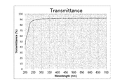
- FIG. 5 is a data showing a transmittance curve (internal transmittance curve) in a column of Example 3 for a sample plate thickness of 0.15 mm and a wavelength range of 200 to 700 nm.
- FIG. 3 is data showing an external transmittance curve in a column of Example 3 for a sample plate thickness of 0.15 mm and a wavelength range of 200 to 700 nm.
- the difference in transmittance between the maximum transmittance and the minimum transmittance in the optical path length of 100 mm and the wavelength range of 400 to 750 nm of the glass plate is preferably 12% or less, 10% or less, 8% or less, 6% or less. 5% or less, particularly 4% or less. If the transmittance difference is too large, the luminance characteristics of the display device are likely to deteriorate.
- the maximum transmittance in an optical path length of 100 mm and a wavelength range of 400 to 750 nm is preferably 88% or more, 90% or more, 91% or more, 92% or more, 93% or more, 94% or more, 95% or more, 96% or more, 97 % Or more, 98% or more, particularly 99% or more. If the maximum transmittance is too low, the luminance characteristics of the display device are likely to deteriorate.
- the maximum transmittance in an optical path length of 200 mm and a wavelength range of 400 to 750 nm is preferably 86% or more, 88% or more, 90% or more, 91% or more, 92% or more, 93% or more, 94% or more, 95% or more, 96 % Or more, 97% or more, 98% or more, particularly 99% or more. If the maximum transmittance is too low, the luminance characteristics of the display device are likely to deteriorate.
- the maximum transmittance in an optical path length of 500 mm and a wavelength range of 400 to 750 nm is preferably 85% or more, 86% or more, 88% or more, 90% or more, 91% or more, 92% or more, 93% or more, 94% or more, 95 % Or more, 96% or more, 97% or more, 98% or more, particularly 99% or more. If the maximum transmittance is too low, the luminance characteristics of the display device are likely to deteriorate.
- the maximum transmittance of the glass plate in an optical path length of 100 mm and a wavelength range of 400 to 750 nm is 85% or more, preferably 87% or more, 88% or more, 89% or more, particularly 90% or more. . If the maximum transmittance is too low, the luminance characteristics of the display device are likely to deteriorate.
- the content of Rh 2 O 3 in the glass plate is less than 1 ppm by mass, preferably 0.8 ppm or less, 0.6 ppm or less, 0.01 to 0.5 ppm, 0.05 to 0.4 ppm, particularly preferably 0.4. 1 to 0.3 ppm. If the content of Rh 2 O 3 is too large, the difference in transmittance between the maximum transmittance and the minimum transmittance in the wavelength range of 400 to 750 nm tends to be excessive. If the content of Rh 2 O 3 is too small, it becomes difficult to use a high-strength Pt—Rh alloy in the glass production facility, and the production cost of the glass plate increases.
- Rh 2 O 3 In order to reduce the content of Rh 2 O 3 as much as possible, a high-purity glass raw material is used, glass manufacturing conditions are adjusted so that Rh 2 O 3 is not mixed, or a Pt—Rh alloy in a glass manufacturing facility. You can reduce the number of use points.
- the content of Cr 2 O 3 in the glass plate is preferably 5 ppm or less, 4 ppm or less, 3 ppm or less, 0.1 to 1.5 ppm, 0.2 to 1 ppm, particularly 0.3 to 0.8 ppm by mass. . If the content of Cr 2 O 3 is too large, the difference in transmittance between the maximum transmittance and the minimum transmittance in the wavelength range of 400 to 750 nm tends to be excessive. Incidentally, when the content of Cr 2 O 3 is too small, the raw material cost, the cost of manufacturing the glass sheet to rise.
- the content of Fe 2 O 3 in the glass plate is preferably 50 ppm or less, 40 ppm or less, 30 ppm or less, 28 ppm or less, 25 ppm or less, 22 ppm or less, 20 ppm or less, 18 ppm or less, 15 ppm or less, 12 ppm or less, 10 ppm or less, 8 ppm or less, 6 ppm or less, particularly 1 to 5 ppm.
- the content of Fe 2 O 3 is too large, the maximum transmittance in an optical path length of 100 mm and a wavelength range of 400 to 750 nm tends to decrease.
- the content of Fe 2 O 3 is less than 1 ppm by mass, it is difficult to reduce the difference in transmittance between the maximum transmittance and the minimum transmittance in the wavelength range of 400 to 750 nm.
- the transmittance near the wavelength 550 nm is relatively high, and the transmittance near the wavelength 400 nm and near the wavelength 750 nm tends to be relatively low. For this reason, if the transmittance near the wavelength 400 nm and the wavelength 750 nm is increased while slightly reducing the transmittance near the wavelength 550 nm, the transmittance difference between the maximum transmittance and the minimum transmittance in the wavelength range 400 to 750 nm is made as much as possible. Can be made smaller.
- the mass ratio Cr 2 O 3 / Fe 2 O 3 is preferably 0.01 to 0.13, 0.0125 to 0.1, 0.014 to 0.06, particularly 0.0167 to 0.0333.
- the light guide plate of the present invention it is preferable to reduce as much as possible the contents of V 2 O 5 , NiO, MnO 2 , Nd 2 O 3 , CeO 2 , and Er 2 O 3 in the glass plate.
- the content of V 2 O 5 in the glass plate is preferably 0.03% by mass or less, 0.02% by mass or less, 0.015% by mass or less, 0.01% by mass or less, 0.005% by mass or less, In particular, it is 0.003 mass% or less.
- the maximum transmittance in an optical path length of 100 mm and a wavelength range of 400 to 750 nm tends to decrease.
- the content of NiO in the glass plate is preferably 0.03% by mass or less, 0.02% by mass or less, 0.015% by mass or less, 0.01% by mass or less, 0.005% by mass or less, particularly preferably It is 003 mass% or less.
- the maximum transmittance in an optical path length of 100 mm and a wavelength range of 400 to 750 nm tends to decrease.
- the content of MnO 2 in the glass plate is preferably 0.03% by mass or less, 0.02% by mass or less, 0.015% by mass or less, 0.01% by mass or less, 0.005% by mass or less, particularly 0 0.003 mass% or less.
- the maximum transmittance in an optical path length of 100 mm and a wavelength range of 400 to 750 nm tends to decrease.
- the content of Nd 2 O 3 in the glass plate is preferably 0.03% by mass or less, 0.02% by mass or less, 0.015% by mass or less, 0.01% by mass or less, 0.005% by mass or less, In particular, it is 0.003 mass% or less.
- the maximum transmittance in an optical path length of 100 mm and a wavelength range of 400 to 750 nm tends to decrease.
- the CeO 2 content in the glass plate is preferably 0.03% by mass or less, 0.02% by mass or less, 0.015% by mass or less, 0.01% by mass or less, 0.005% by mass or less, particularly 0 0.003 mass% or less.
- the maximum transmittance in an optical path length of 100 mm and a wavelength range of 400 to 750 nm tends to decrease.
- the content of Er 2 O 3 in the glass plate is preferably 0.03% by mass or less, 0.02% by mass or less, 0.015% by mass or less, 0.01% by mass or less, 0.005% by mass or less, In particular, it is 0.003 mass% or less.
- the maximum transmittance in an optical path length of 100 mm and a wavelength range of 400 to 750 nm tends to decrease.
- the dimension of at least one side of the glass plate is preferably 1000 mm or more, 1500 mm or more, 2000 mm or more, 2500 mm or more, particularly 3000 mm or more. In this way, it is possible to satisfy the demand for an increase in the size of the display device.
- the thermal expansion coefficient of the glass plate is preferably 120 ⁇ 10 ⁇ 7 / ° C. or lower, 95 ⁇ 10 ⁇ 7 / ° C. or lower, 70 ⁇ 10 ⁇ 7 / ° C. or lower, 60 ⁇ 10 ⁇ 7 / ° C. or lower, particularly 50 ⁇ 10 -7 / ° C or less. If the thermal expansion coefficient is too high, the difference in dimensional change due to heat between the display panel and the light guide plate becomes large.
- the strain point of the glass plate is preferably 460 ° C. or higher, 480 ° C. or higher, 500 ° C. or higher, 520 ° C. or higher, 530 ° C. or higher, 550 ° C. or higher, particularly 590 ° C. or higher. If the strain point is too low, the heat resistance of the glass plate tends to be lowered. For example, when a reflective film, a diffusion film, or the like is formed on the surface or end surface of the glass plate at a high temperature, the glass plate is likely to be thermally deformed.
- the “strain point” is a value measured based on JIS R3103.
- the glass plate has a glass composition of 40% by mass to SiO 2 40 to 80%, Al 2 O 3 1 to 15%, B 2 O 3 0 to 20%, Na 2 O 0 to 20%, MgO 0 to 10%. CaO 0 to 15%, SrO 0 to 15% and BaO 0 to 35% are preferably contained.
- % display means the mass%.
- SiO 2 is a component that serves as a network former of glass, and is a component that reduces a thermal expansion coefficient and reduces a dimensional change due to heat. It is a component that increases acid resistance and strain point.
- the preferable lower limit range of SiO 2 is 40% or more, 60% or more, 65% or more, 67% or more, particularly 70% or more, and the preferable upper limit range is 80% or less, 78% or less, 77% or less, 75%. Hereinafter, it is particularly 73% or less.
- the content of SiO 2 is increased, the high temperature viscosity is increased, the meltability is lowered, and the devitrification blisters of cristobalite are liable to precipitate at the time of molding.
- the content of SiO 2 decreases, the coefficient of thermal expansion increases and the dimensional change due to heat tends to increase. In addition, acid resistance and strain point are likely to be lowered.
- Al 2 O 3 is a component that lowers the thermal expansion coefficient and reduces dimensional changes due to heat. It also has the effect of increasing the strain point and suppressing the precipitation of devitrified cristobalite during molding.
- the preferred lower limit range of Al 2 O 3 is 1% or more, 2% or more, 5.5% or more, 7% or more, particularly 10% or more, and the preferred upper limit range is 15% or less, 13% or less, particularly 12 % Or less.
- B 2 O 3 is a component that acts as a flux, lowers the high temperature viscosity, and improves the meltability. Moreover, it is a component which reduces a thermal expansion coefficient and reduces the dimensional change by a heat
- the preferred lower limit range of B 2 O 3 is 0% or more, 3% or more, 5% or more, 7% or more, 8% or more, particularly 10% or more, and the preferred upper limit range is 15% or less, 13% or less, In particular, it is 12% or less.
- the content of B 2 O 3 is increased, the strain point and acid resistance are likely to be lowered.
- the content of B 2 O 3 decreases, the thermal expansion coefficient increases and the dimensional change due to heat tends to increase. In addition, the meltability tends to be lowered.
- Na 2 O is a component that lowers the high temperature viscosity and improves the meltability.
- the preferred lower limit range of Na 2 O is 0% or more, 3% or more, 5% or more, 6% or more, 7% or more, particularly 10% or more, and the preferred upper limit range is 20% or less, 18% or less, 16 % Or less, particularly 15% or less.
- the content of Na 2 O increases, the coefficient of thermal expansion increases and the dimensional change due to heat tends to increase.
- the content of Na 2 O is reduced, the meltability is likely to be lowered.
- MgO is a component that lowers high temperature viscosity and improves meltability.
- the preferred lower limit range of MgO is 0% or more, 0.05% or more, particularly 0.1% or more, and the preferred upper limit range is 10% or less, 6% or less, 2% or less, 1% or less, especially 0. 5% or less.
- CaO is a component that improves the meltability by lowering only the high temperature viscosity without lowering the strain point.
- the preferred lower limit range of CaO is 0% or more, 0.5% or more, 1% or more, particularly 2% or more, and the preferred upper limit range is 15% or less, 14% or less, 13% or less, 8% or less, particularly 5% or less.
- SrO is a component that improves chemical resistance and devitrification resistance.
- a preferable lower limit range of SrO is 0% or more, 0.1% or more, particularly 0.5% or more, and a preferable upper limit range is 15% or less, 10% or less, particularly 5% or less.
- BaO is a component that improves chemical resistance and devitrification resistance.
- the preferable lower limit range of BaO is 0% or more, 0.1% or more, particularly 0.5% or more, and the preferable upper limit range is 35% or less, 30% or less, 20% or less, particularly 10% or less.
- the content of BaO increases, the density increases or the thermal expansion coefficient increases, and the dimensional change due to heat tends to increase. In addition, the meltability tends to be lowered.
- the preferred lower limit range of the total amount of MgO and CaO is 0% or more, 0.1% or more, 0.5% or more, particularly 1% or more, and the preferred upper limit range is 10% or less, 8% or less, 5% Below, 3% or less, especially 2% or less.
- the total amount of MgO and CaO is too large, the thermal expansion coefficient and density are unreasonably high, and the devitrification resistance tends to be lowered.
- the preferred lower limit range of the total amount of SrO and BaO is 0% or more, 0.1% or more, 1% or more, 1.5% or more, particularly 2% or more, and the preferred upper limit range is 35% or less, 20%. Below, 10% or less, especially 5% or less. If the total amount of SrO and BaO is too small, the meltability tends to decrease. On the other hand, when the total amount of SrO and BaO is too large, the thermal expansion coefficient and density are unreasonably high, and the devitrification resistance tends to be lowered.
- Rh 2 O 3 , Cr 2 O 3 , Fe 2 O 3 , V 2 O 5 , NiO, MnO 2 , Nd 2 O 3 , CeO 2 and Er 2 O 3 are as described above. .
- Y 2 O 3 , La 2 O 3 , Nb 2 O 5 , P 2 O 5 are each reduced to 3%
- Li 2 O, K 2 O, Cs 2 O may be introduced up to 6% each
- As 2 O 3 , Sb 2 O 3 , SnO 2 , SO 3 , F, Cl, etc. may be introduced as a clarifier up to 2% in total.
- As 2 O 3 and Sb 2 O 3 are environmentally hazardous substances, and when a glass plate is formed by the float process, it is reduced in the float bath to become a metal foreign object, so avoid substantial introduction. More specifically, the content is preferably less than 0.01%.
- the glass plate is preferably formed by an overflow down draw method.
- an overflow down draw method it is difficult to produce a temperature difference and composition difference between the front and back surfaces of the glass ribbon during molding, and it becomes easy to form a glass plate that is unpolished and has good surface quality.
- the manufacturing cost of the light guide plate is low.
- uniform brightness characteristics The reason for this is that, in the case of the overflow downdraw method, the surface to be the surface does not come into contact with the bowl-like refractory and is molded in a free surface state.
- the glass plate can be formed by a slot downdraw method, a float method, a rollout method, a redraw method, or the like.
- a temperature difference and a composition difference between the front and back surfaces of the glass ribbon are likely to occur during molding.
- the temperature difference and the composition difference can be reduced.
- a dot pattern is printed on one surface (preferably a light exit surface) of the glass plate, and the diameter of the dot of the dot pattern is from the end surface where light from the light source should enter. It is more preferable that the distance gradually increases as the distance increases. If it does in this way, it will become easy to equalize the light radiate
- the dot pattern can be formed, for example, by printing heat resistant ink or glass frit on the surface of a glass plate.
- the average surface roughness Ra of the end face of the glass plate is preferably 0.5 ⁇ m or less, 0.3 ⁇ m or less, 0.2 ⁇ m or less, particularly 0.1 ⁇ m or less. This makes it easy to reduce optical loss when light from the light source enters the end face. Moreover, it becomes easy to form a high-quality reflective layer on the end face.
- the average surface roughness Ra of the end surface of the glass plate can be reduced as much as possible.
- the average surface roughness Ra of the end surface of the glass plate can be reduced without causing polishing scratches.
- the end face of the glass plate preferably has no chamfered portion. If it does in this way, it will become easy to take in the light from a light source to the inside of a glass plate.
- a reflection layer is preferably formed on all or a part of the end surface other than the end surface on which light from the light source is incident, and all of the end surfaces other than the end surface on which light from the light source is incident. It is particularly preferable that a reflective layer is formed on the surface. If it does in this way, the light which propagated inside the glass plate will become difficult to leak from an end face. Note that, as the reflective layer, a reflective film may be directly formed on the end face, but a reflective seal may be attached to the end face.
- a diffusion plate in order to diffuse the light emitted from the light emitting surface, a diffusion plate may be attached to the light emitting surface, or a diffusion layer may be formed on the light emitting surface.
- the light guide plate of the present invention can also be used as a substrate for a display panel having the function of a light guide plate. In this way, the member configuration of the display device can be simplified.
- the glass plate of the present invention is characterized by having an optical path length of 500 mm and a transmittance of 93% or more in a wavelength range of 400 to 750 nm.
- the glass plate of the present invention is characterized in that the difference in transmittance between the maximum transmittance and the minimum transmittance in the wavelength range of 400 to 750 nm is 6% or less. Since the technical features of the glass plate of the present invention have already been described in the description column of the light guide plate of the present invention, detailed description thereof is omitted here.
- the transmittance at an optical path length of 0.15 mm and a wavelength of 250 nm is preferably 85% or more, 88% or more, 90% or more, 92% or more, 94% or more, 95% or more, particularly 96% or more. It is. If the transmittance at an optical path length of 0.15 mm and a wavelength of 250 nm is too low, it will be difficult to deploy to applications requiring sterilization and virus killing.
- Table 1 shows examples of the present invention (sample Nos. 1 to 4).
- a glass batch in which glass raw materials were prepared so as to have the glass composition shown in the table was placed in a platinum crucible and then melted at 1200 to 1450 ° C. for 24 hours. In melting the glass batch, the mixture was stirred and homogenized using a platinum stirrer. Next, the molten glass was poured onto a carbon plate and formed into a plate shape, and then slowly cooled at a temperature near the annealing point for 30 minutes. For each of the obtained samples, the thermal expansion coefficient CTE, the strain point Ps in the temperature range of 30 to 380 ° C., the maximum transmittance and the minimum transmittance in the wavelength range of 400 to 700 nm were evaluated.
- the thermal expansion coefficient CTE in the temperature range of 30 to 380 ° C. is a value obtained by measuring the average thermal expansion coefficient at 30 to 380 ° C. based on JIS R3102 using a dilatometer.
- the strain point is a value measured based on JIS R3103.
- the maximum transmittance and the minimum transmittance are values measured by UV-3100PC manufactured by Shimadzu Corporation.
- sample no. Nos. 1 to 4 have a high strain point, high heat resistance, and a low thermal expansion coefficient compared to the resin plate. Therefore, dimensional change hardly occurs with a rise in temperature, and the maximum transmittance in the wavelength range of 400 to 750 nm. The transmittance difference of the minimum transmittance is small. Therefore, sample no. 1 to 4 are considered to be suitable as a light guide plate, particularly as a light guide plate used in an edge light type surface light emitting device.
- a glass raw material As a glass raw material, a high-purity glass raw material with few colored impurities, such as Fe 2 O 3, is used, and a colored component such as Rh 2 O 3 is not mixed into the glass from the glass plate manufacturing equipment. A designed glass production facility was used.
- the transmittance in an optical path length of 150 mm and a wavelength range of 400 to 750 nm was measured, and then converted into an internal transmittance of an optical path length of 500 mm.
- the maximum transmittance in the wavelength range of 400 to 750 nm was 99%, and the difference in transmittance between the maximum transmittance and the minimum transmittance in the wavelength range of 400 to 750 nm was 3%.
- FIG. 3 shows a transmittance curve in an optical path length of 500 mm and a wavelength range of 400 to 750 nm.
- the obtained glass plate was measured for the thermal expansion coefficient CTE in the temperature range of 30 to 380 ° C. by the above method, it was 66.3 ⁇ 10 ⁇ 7 / ° C., and the strain point was measured. 536 ° C.
- the light guide plate having this glass plate is less likely to undergo dimensional changes with increasing temperature and can improve the luminance characteristics of the display device.
- the Rh 2 O 3 content in the glass plate is less than 0.2 ppm
- the Fe 2 O 3 content is 4 ppm by mass
- the Cr 2 O 3 content is less than 0.1 ppm.
- a glass raw material a high-purity glass raw material with few colored impurities, such as Fe 2 O 3, is used, and a colored component such as Rh 2 O 3 is not mixed into the glass from the glass plate manufacturing equipment. A designed glass production facility was used.
- FIG. 4 is data showing a transmittance curve (internal transmittance curve) in the wavelength range of 200 to 700 nm of this sample
- FIG. 5 is data showing an external transmittance curve in the wavelength range of 200 to 750 nm.
- the transmittance (internal transmittance) at a wavelength of 250 nm of this sample was 96%, and the external transmittance was 88%.
- this glass sample is suitable for applications that require sterilization and virus killing because it penetrates deep ultraviolet rays well, and has a higher coefficient of thermal expansion than quartz glass. Excellent sealing and sealing properties.
- the glass plate of the present invention is suitable for applications requiring high transmittance in addition to the light guide plate.
- it is suitable for glass substrates for displays, glass substrates for optical communication devices, glass substrates for semiconductor manufacturing processes, and the like.
- the glass plate of the present invention has a high transmittance in the deep ultraviolet region and a thermal expansion coefficient higher than that of quartz glass, it can be developed in a wide range of fields such as medical treatment, analysis, environment, and agricultural industry.
- the glass according to the present invention has high transmittance in the ultraviolet region, it can be processed into a tube shape and suitably used as a sterilizing lamp.
Landscapes
- Chemical & Material Sciences (AREA)
- Engineering & Computer Science (AREA)
- Materials Engineering (AREA)
- Chemical Kinetics & Catalysis (AREA)
- General Chemical & Material Sciences (AREA)
- Geochemistry & Mineralogy (AREA)
- Life Sciences & Earth Sciences (AREA)
- Organic Chemistry (AREA)
- Physics & Mathematics (AREA)
- General Physics & Mathematics (AREA)
- Optics & Photonics (AREA)
- General Engineering & Computer Science (AREA)
- Glass Compositions (AREA)
Abstract
Cette invention concerne une plaque de guidage de lumière, comprenant au moins une plaque de verre et caractérisée en ce que : la teneur en Rh2O3 dans la plaque de verre est inférieure à 1 ppm en masse ; et la différence de coefficient de transmission entre le coefficient de transmission maximal et le coefficient de transmission minimal d'une longueur de trajet optique de 100 mm de la plaque de verre à l'intérieur de la plage de longueurs d'onde de 400 à 750 nm est inférieure ou égale à 12 %.
Priority Applications (2)
| Application Number | Priority Date | Filing Date | Title |
|---|---|---|---|
| KR1020177026465A KR102538383B1 (ko) | 2015-06-24 | 2016-06-14 | 도광판 |
| CN201680031022.1A CN107615120B (zh) | 2015-06-24 | 2016-06-14 | 导光板 |
Applications Claiming Priority (8)
| Application Number | Priority Date | Filing Date | Title |
|---|---|---|---|
| JP2015126113 | 2015-06-24 | ||
| JP2015-126113 | 2015-06-24 | ||
| JP2015-164476 | 2015-08-24 | ||
| JP2015164476 | 2015-08-24 | ||
| JP2015165633 | 2015-08-25 | ||
| JP2015-165633 | 2015-08-25 | ||
| JP2015198193A JP6765628B2 (ja) | 2015-06-24 | 2015-10-06 | 導光板 |
| JP2015-198193 | 2015-10-06 |
Publications (1)
| Publication Number | Publication Date |
|---|---|
| WO2016208451A1 true WO2016208451A1 (fr) | 2016-12-29 |
Family
ID=57585254
Family Applications (1)
| Application Number | Title | Priority Date | Filing Date |
|---|---|---|---|
| PCT/JP2016/067619 Ceased WO2016208451A1 (fr) | 2015-06-24 | 2016-06-14 | Plaque de guidage de lumière |
Country Status (1)
| Country | Link |
|---|---|
| WO (1) | WO2016208451A1 (fr) |
Cited By (2)
| Publication number | Priority date | Publication date | Assignee | Title |
|---|---|---|---|---|
| WO2018159385A1 (fr) * | 2017-02-28 | 2018-09-07 | 日本電気硝子株式会社 | Plaque de guidage de lumière |
| US12319615B2 (en) | 2021-01-22 | 2025-06-03 | AGC Inc. | Float glass substrate |
Citations (6)
| Publication number | Priority date | Publication date | Assignee | Title |
|---|---|---|---|---|
| JPH0558668A (ja) * | 1991-08-31 | 1993-03-09 | Shinetsu Quartz Prod Co Ltd | 紫外線レーザー用合成石英ガラス光学部材 |
| JP2006036626A (ja) * | 2004-06-23 | 2006-02-09 | Nippon Electric Glass Co Ltd | 無アルカリガラス基板 |
| JP2007101799A (ja) * | 2005-10-03 | 2007-04-19 | Nippon Sheet Glass Co Ltd | 透過型光学素子 |
| JP2010248046A (ja) * | 2009-04-17 | 2010-11-04 | Nippon Electric Glass Co Ltd | ガラス |
| JP2014209465A (ja) * | 2013-03-27 | 2014-11-06 | 三京化成工業株式会社 | 面光源およびその製法 |
| JP2015069792A (ja) * | 2013-09-27 | 2015-04-13 | 凸版印刷株式会社 | 導光体、照明装置、および表示装置 |
-
2016
- 2016-06-14 WO PCT/JP2016/067619 patent/WO2016208451A1/fr not_active Ceased
Patent Citations (6)
| Publication number | Priority date | Publication date | Assignee | Title |
|---|---|---|---|---|
| JPH0558668A (ja) * | 1991-08-31 | 1993-03-09 | Shinetsu Quartz Prod Co Ltd | 紫外線レーザー用合成石英ガラス光学部材 |
| JP2006036626A (ja) * | 2004-06-23 | 2006-02-09 | Nippon Electric Glass Co Ltd | 無アルカリガラス基板 |
| JP2007101799A (ja) * | 2005-10-03 | 2007-04-19 | Nippon Sheet Glass Co Ltd | 透過型光学素子 |
| JP2010248046A (ja) * | 2009-04-17 | 2010-11-04 | Nippon Electric Glass Co Ltd | ガラス |
| JP2014209465A (ja) * | 2013-03-27 | 2014-11-06 | 三京化成工業株式会社 | 面光源およびその製法 |
| JP2015069792A (ja) * | 2013-09-27 | 2015-04-13 | 凸版印刷株式会社 | 導光体、照明装置、および表示装置 |
Cited By (3)
| Publication number | Priority date | Publication date | Assignee | Title |
|---|---|---|---|---|
| WO2018159385A1 (fr) * | 2017-02-28 | 2018-09-07 | 日本電気硝子株式会社 | Plaque de guidage de lumière |
| JPWO2018159385A1 (ja) * | 2017-02-28 | 2020-01-16 | 日本電気硝子株式会社 | 導光板 |
| US12319615B2 (en) | 2021-01-22 | 2025-06-03 | AGC Inc. | Float glass substrate |
Similar Documents
| Publication | Publication Date | Title |
|---|---|---|
| EP3365595B1 (fr) | Plaque de guide de lumière à transmission élevée | |
| EP3971147B1 (fr) | Verres d'aluminosilicate | |
| JP6765628B2 (ja) | 導光板 | |
| KR102138067B1 (ko) | 도광판 | |
| JP6516085B2 (ja) | 導光板 | |
| WO2018031892A1 (fr) | Procédé et appareil pour unité stratifiée de rétroéclairage | |
| JP7429093B2 (ja) | 導光板 | |
| TWI792533B (zh) | 高透射性玻璃 | |
| CN109477626A (zh) | 包含光提取特征的玻璃制品 | |
| TWI738867B (zh) | 具有鹼土金屬氧化物做為改質劑的高透射性玻璃 | |
| WO2016208451A1 (fr) | Plaque de guidage de lumière | |
| WO2018159385A1 (fr) | Plaque de guidage de lumière |
Legal Events
| Date | Code | Title | Description |
|---|---|---|---|
| 121 | Ep: the epo has been informed by wipo that ep was designated in this application |
Ref document number: 16814222 Country of ref document: EP Kind code of ref document: A1 |
|
| ENP | Entry into the national phase |
Ref document number: 20177026465 Country of ref document: KR Kind code of ref document: A |
|
| NENP | Non-entry into the national phase |
Ref country code: DE |
|
| 122 | Ep: pct application non-entry in european phase |
Ref document number: 16814222 Country of ref document: EP Kind code of ref document: A1 |