WO2016208583A1 - Outil de maintien de cible, dispositif de mesure, et procédé de maintien de cible - Google Patents
Outil de maintien de cible, dispositif de mesure, et procédé de maintien de cible Download PDFInfo
- Publication number
- WO2016208583A1 WO2016208583A1 PCT/JP2016/068404 JP2016068404W WO2016208583A1 WO 2016208583 A1 WO2016208583 A1 WO 2016208583A1 JP 2016068404 W JP2016068404 W JP 2016068404W WO 2016208583 A1 WO2016208583 A1 WO 2016208583A1
- Authority
- WO
- WIPO (PCT)
- Prior art keywords
- target
- measurement object
- guide
- magnet
- holding jig
- Prior art date
- Legal status (The legal status is an assumption and is not a legal conclusion. Google has not performed a legal analysis and makes no representation as to the accuracy of the status listed.)
- Ceased
Links
Images




Classifications
-
- G—PHYSICS
- G01—MEASURING; TESTING
- G01B—MEASURING LENGTH, THICKNESS OR SIMILAR LINEAR DIMENSIONS; MEASURING ANGLES; MEASURING AREAS; MEASURING IRREGULARITIES OF SURFACES OR CONTOURS
- G01B21/00—Measuring arrangements or details thereof, where the measuring technique is not covered by the other groups of this subclass, unspecified or not relevant
-
- G—PHYSICS
- G01—MEASURING; TESTING
- G01C—MEASURING DISTANCES, LEVELS OR BEARINGS; SURVEYING; NAVIGATION; GYROSCOPIC INSTRUMENTS; PHOTOGRAMMETRY OR VIDEOGRAMMETRY
- G01C15/00—Surveying instruments or accessories not provided for in groups G01C1/00 - G01C13/00
- G01C15/02—Means for marking measuring points
- G01C15/06—Surveyors' staffs; Movable markers
-
- G—PHYSICS
- G01—MEASURING; TESTING
- G01B—MEASURING LENGTH, THICKNESS OR SIMILAR LINEAR DIMENSIONS; MEASURING ANGLES; MEASURING AREAS; MEASURING IRREGULARITIES OF SURFACES OR CONTOURS
- G01B11/00—Measuring arrangements characterised by the use of optical techniques
- G01B11/08—Measuring arrangements characterised by the use of optical techniques for measuring diameters
-
- G—PHYSICS
- G01—MEASURING; TESTING
- G01B—MEASURING LENGTH, THICKNESS OR SIMILAR LINEAR DIMENSIONS; MEASURING ANGLES; MEASURING AREAS; MEASURING IRREGULARITIES OF SURFACES OR CONTOURS
- G01B11/00—Measuring arrangements characterised by the use of optical techniques
- G01B11/24—Measuring arrangements characterised by the use of optical techniques for measuring contours or curvatures
Definitions
- Measured devices that measure the distance to a measurement object include devices that use measurement light.
- Patent Literature 1 receives a light source that outputs a radiated light beam (measurement light), a target that includes an external retroreflector that reflects the measurement light, and light that is fixed integrally with the light source and reflected from the target.
- An absolute distance meter having a light receiving unit and a signal processing device that analyzes the light received by the light receiving unit and calculates the distance to the target is described.
- the absolute distance meter irradiates the target with measurement light from the light source while the target is in contact with the measurement object, receives the light reflected by the target at the light receiving unit, analyzes the received light, By calculating the distance, the distance to the measurement object in contact with the target can be measured.
- Patent Document 2 as a jig for holding a spherical reflector (target) used for measuring a bending angle of a rod-like work (pipe) such as a cylinder or a column, an outer part that holds the spherical reflector in a slidable manner is disclosed.
- a jig that includes a pair of semicircular jig structures having orientation grooves formed therein, and that the pair of semicircular jig structures are combined and fitted to the outer periphery of a pipe.
- the bending angle for each measurement part of the bar-shaped workpiece is recorded. Is going to be possible.
- a plate-like member such as a seal fin of a steam turbine may be an object to be measured.
- the object to be measured becomes thinner, unlike a rod-like workpiece such as a cylinder or a column. Since the target is spherical, when the target is brought into contact with the measurement object or moved along the measurement object, the contact position of the target is easily shifted in the thickness direction (plate thickness direction) of the measurement object. . Thus, when the contact position of the target shifts, the plate-shaped measurement object comes in contact with a direction shifted from the normal line toward the center of the spherical target, resulting in a measurement error.
- the target holding jig described in Patent Document 3 can bring the target into contact with the measurement object with high accuracy, but it is necessary to improve operability.
- the connecting portion may be a mechanism such as a magnet that is connected to an object to be measured by adsorption.
- the holding-type connecting portion is simply replaced with a magnet, it is notable. It is difficult to improve operability.
- a target holding jig is a material that holds a target including a reflection mechanism that reflects measurement light emitted from a light source, and is capable of magnetically attracting the target and a magnet.
- suction state with respect to a measuring object can be ensured, guiding the contact of the contact part of the target with respect to the end surface of a measuring object.
- the position of the guide portion can be adjusted according to the dimension of the measurement object, and the target It is possible to improve the accuracy of the guidance of the position that comes into contact with the measurement object, or improve the accuracy of the position where the connecting portion magnetically attracts the measurement object.
- magnetic adsorption to the measurement object can be easily performed and can be easily removed from the measurement object. Thereby, attachment / detachment with respect to a measuring object can be performed easily.
- the magnet has a flat surface along a side surface that is a surface extending in a direction orthogonal to the end surface and an extending direction of the end surface of the measurement object,
- the flat surface is preferably separated from the position of the contact portion of the target that contacts the measurement object by the dimension of the measurement object in the short direction of the end surface of the measurement object.
- the contact portion of the target is arranged with respect to the measurement object by magnetically attracting the flat surface of the magnet to the measurement object, the contact portion of the target is easily and high with respect to the measurement object. Can be contacted with accuracy.
- the guide portion has a side surface on which the other guide surface is a surface extending in an extending direction of the end surface of the measurement object and a direction orthogonal to the end surface. It is preferable that the magnet is fixed to the other guide surface at each position on both sides of the target in the long side direction of the end surface of the measurement object.
- each connecting portion is magnetically attracted and connected to the side surface of the measurement object on both sides of the target, so that the target can be brought into contact with the measurement object in a stable connection state.
- the magnet is preferably a neodymium-based permanent magnet.
- the target can be more reliably brought into contact with the measurement object, and the measurement accuracy can be further increased.
- this can prevent the connecting portion and the target from being electrically connected at a portion other than the circuit.
- a target holding method is a method for holding a target including a reflection mechanism that reflects measurement light emitted from a light source, and an end surface of a measurement object formed of a material capable of magnetically attracting the target and a magnet.
- a guide unit that guides a position where the target contacts the measurement object in a short side direction of the end surface of the sensor, and a coupling unit that is fixed to the guide unit and includes a magnet that can be magnetically attracted to the measurement object.
- the magnet has a flat surface along a side surface that is a surface extending in a direction orthogonal to the end surface and an extending direction of the end surface of the measurement object, and magnetic absorption is performed on the side surface of the measurement object.
- the guide portion is a space having a thickness equal to or greater than the thickness of the measurement object from the flat surface of the magnet to the side surface opposite to the side surface in a state where the magnet is magnetically attracted to the side surface of the measurement object.
- the magnet of the connecting part is connected to the measurement object by magnetic attraction, and the relative position between the target and the measurement object is regulated by the guide part, so that the target can be brought into contact with the measurement object with high accuracy.
- one target holding jig and a target can be used for the measurement of several points by connecting with a measuring object in the state in which a connection part is removable with a magnet.
- the connecting portion is configured to magnetically attract to the measurement object, the connection to the measurement object can be easily performed.
- the connection part is arrange
- the connecting portion can be easily connected to the measurement object, and a high magnetic attraction force can be ensured by magnetic attraction between the surfaces.
- the magnet of the target holding jig extends along only one side surface that is an extending direction of the end surface of the measurement object and a surface extending in a direction orthogonal to the end surface.
- the flat surface of the magnet is magnetically attracted only to one side surface of the measurement object.
- the magnetic adsorption to the measurement object can be easily performed, and the magnetic adsorption from the measurement object can be easily removed, so that the measurement object can be easily attached and detached.
- the guide portion of the target holding jig sandwiches two side surfaces which are the extending direction of the end surface of the measurement object and a surface extending in a direction perpendicular to the end surface 2
- the contact portion of the target that contacts the end surface of the measurement object is disposed between the guide surfaces, and one of them is provided so as to be movable toward or away from the other.
- the accuracy of guiding the position where the target contacts the measurement object can be improved, and the connecting portion can be magnetically attracted to the measurement object.
- the accuracy of the position to be performed can be improved.
- the target holding jig includes a detection unit that detects that the target and the measurement object are in contact, and the detection unit includes the target and the measurement object. It is preferable that a notification unit for notifying that the contact is detected is further provided, and that in the connection step, the connection is completed when the notification by the notification unit is received.
- the measurement object is preferably an annular seal fin in a steam turbine.
- the measurement object is a seal fin
- it is necessary to measure a large number of positions but by using a detachable target holding jig, the target is placed on the measurement object and moved for measurement. Measurement can be performed with a small number of targets.
- the measurement object such as a plate-like member such as a seal fin of the steam turbine and the connection part are connected by magnetic adsorption, and the target and the measurement object are relative to each other in the guide part.
- the target By regulating the position, the target can be brought into contact with a measurement object that is a plate-like member such as a seal fin of a steam turbine with high accuracy by an easy operation.
- FIG. 1 is a front view showing a schematic configuration of a target holding jig according to an embodiment of the present invention.
- FIG. 2 is a top view of the target holding jig shown in FIG.
- FIG. 3 is a bottom view of the target holding jig shown in FIG.
- FIG. 4 is a cross-sectional view showing a schematic configuration viewed from the line AA in FIG.
- FIG. 5 is a cross-sectional view showing a schematic configuration viewed from the line BB in FIG.
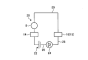
- FIG. 6 is a schematic diagram illustrating a circuit configuration of the detection unit.
- FIG. 7 is a schematic diagram illustrating a schematic configuration of a measurement apparatus including a target holding jig.
- FIG. 8 is a perspective view showing a schematic configuration of the measurement object.
- FIG. 9 is a schematic diagram showing a positional relationship between the measurement object and the target holding jig during measurement.
- the target holding jig and the measuring device of the present invention will be described by taking an example of measuring the end surface on the inner peripheral side of the ring-shaped seal fin of the steam turbine.
- the magnet is not limited to this as long as it is made of a magnetically attractable material (including a magnetic material).
- the target holding jig and the measuring device of the present invention can obtain a more remarkable effect when the seal fin is used as a measurement object.
- the position of the end face of the thin plate-like measurement object is measured. In this case, it can be suitably used.
- FIG. 1 is a front view showing a schematic configuration of a target holding jig according to an embodiment of the present invention.
- FIG. 2 is a top view of the target holding jig shown in FIG.
- FIG. 3 is a bottom view of the target holding jig shown in FIG.
- FIG. 4 is a cross-sectional view showing a schematic configuration viewed from the line AA in FIG.
- FIG. 5 is a cross-sectional view showing a schematic configuration viewed from the line BB in FIG.
- FIG. 6 is a schematic diagram illustrating a circuit configuration of the detection unit.
- the target holding jig 10 holds the target 8 and is detachably connected to the measurement object 50.
- the target 8 is a part of a measuring apparatus described later, and includes a reflection mechanism that reflects measurement light.
- the target 8 is a substantially spherical member partially formed with a notch, and a reflector that reflects measurement light is provided in the notch.
- the measurement object 50 of the present embodiment is a ring-shaped seal fin of a steam turbine (hereinafter, the measurement object 50 is also referred to as a seal fin 50).
- the target holding jig 10 includes a support part 14, a connecting part 15, a guide part 20, a battery folder 22, a light emitting part 24, a wiring 26, and a wiring 28.
- the support portion 14 is a member that becomes a base of the target holding jig 10. As shown in FIGS. 1 to 5, the support portion 14 includes a first support portion 14A and a second support portion 14B. Each of the first support portion 14A and the second support portion 14B is a plate-like member, and is connected by a screw 14D via a spacer 14C having a predetermined interval between the inner surfaces having the largest areas facing each other. ing. In the first support portion 14A, an opening portion 14Aa penetrating the inner and outer surfaces having the largest area is formed. Further, the second support portion 14B is formed with an opening 14Ba penetrating the inner and outer surfaces having the largest area.
- the openings 14Aa and 14Ba are provided so as to face each other and have an inner diameter slightly smaller than the diameter of the target 8. Then, by inserting the target 8 into each opening 14Aa, 14Ba, the target 8 places its center C between the first support part 14A and the second support part 14B, and the first support part 14A and the second support part 14B. It is held by the target holding jig 10 by being sandwiched between the support portions 14B and being held at predetermined positions in the openings 14Aa and 14Ba. 2 and 3, the openings 14 ⁇ / b> Aa and 14 ⁇ / b> Ba are shown as rectangular shapes, but may be circular, for example, and the shape is not limited as long as it has an inner diameter smaller than the diameter of the target 8.
- the notch 14Ab extended to the side surface of 14 A of 1st support parts is formed.
- the outer surface having the largest area is a surface facing the end surface 50a of the measurement object 50 when facing the measurement object (seal fin) 50 as shown in FIG. .
- the battery folder 22 and the light emitting unit 24 are arranged on the outer surface facing away from the measurement object 50.
- a wiring 26 and a wiring 28 are arranged in association with the battery folder 22 and the light emitting unit 24.
- the guide part 20 is arrange
- the guide part 20 is arrange
- the guide part 20 includes a first guide part 20A and a second guide part 20B.
- the first guide portion 20 ⁇ / b> A and the second guide portion 20 ⁇ / b> B are arranged with the top portion 8 a of the target 8 that protrudes most from the opening portion 14 ⁇ / b> Ba on the outer surface of the second support portion 14 ⁇ / b> B. It is provided facing.
- the top 8 a of the target 8 is a contact portion that contacts the end surface 50 a of the measurement object 50.
- the first guide portion 20A and the second guide portion 20B are provided with flat guide surfaces 20Aa and 20Ba facing each other with the top portion 8a of the target 8 therebetween.
- Each guide surface 20Aa, 20Ba is provided along the longitudinal direction in which the measurement object 50 extends, as shown in FIG.
- channel 21 which put the top part 8a of the target 8 is formed between each guide surface 20Aa and 20Ba. Further, as shown in FIGS.
- the first guide portion 20 ⁇ / b> A and the second guide portion 20 ⁇ / b> B have an opening hole 20 ⁇ / b> Ab for inserting a part of the target 8 protruding from the opening portion 14 ⁇ / b> Ba of the second support portion 14 ⁇ / b> B, 20Bb is formed.
- the opening holes 20Ab and 20Bb prevent the first guide part 20A and the second guide part 20B from interfering with the target 8.
- the first guide portion 20A is provided such that the guide surface 20Aa extends to both sides of the target 8 with the target 8 positioned substantially at the center.
- the first guide portion 20A has a fixed piece 20Ac that is bent perpendicular to the guide surface 20Aa, and the fixed piece 20Ac is fixed to the second support portion 14B by a screw 20Ad.
- the guide surface 20 ⁇ / b> Aa is along the one side surface 50 b of the measurement object 50. Further, as shown in FIGS.
- the first guide portion 20 ⁇ / b> A is located at a position protruding from the second support portion 14 ⁇ / b> B rather than the protruding height of the top portion 8 a of the target 8 protruding from the second support portion 14 ⁇ / b> B.
- a guide surface 20Aa is disposed.
- the side surface 50b of the measuring object 50 is a surface extending in the extending direction of the end surface 50a of the measuring object 50 and the direction orthogonal to the end surface 50a.
- the second guide portion 20B is formed such that the guide surface 20Ba is smaller than the guide surface 20Aa of the first guide portion 20A.
- the second guide portion 20B has a fixing piece 20Bc that bends perpendicularly to the guide surface 20Ba, and the fixing piece 20Bc is fixed to the second support portion 14B by screws 20Bd.
- the guide surface 20Ba is along the other side surface 50b of the measurement object 50.
- the second guide portion 20B is formed as a long hole 20Be in which a hole into which the screw 20Bd is inserted is formed in a longitudinal shape in a direction toward the first guide portion 20A.
- the second guide portion 20B is provided so that the guide surface 20Ba can move toward or away from the guide surface 20Aa of the first guide portion 20A by loosening the screw 20Bd. That is, the guide part 20 is provided so that the space
- the connecting portion 15 includes a magnet 16 and a magnet 18.
- the magnet 16 and the magnet 18 are coupled so as to be magnetically attractable to a measurement object 50 made of a material (including a magnetic body) on which the magnet can be magnetically attracted.
- the magnet 16 and the magnet 18 are arranged on the guide surface 20 ⁇ / b> Aa of the first guide portion 20 ⁇ / b> A in the guide portion 20.
- the magnet 16 and the magnet 18 are in the long side direction of the end surface 50a of the measurement object 50 in the guide surface 20Aa provided to extend to both sides of the target 8 along the side surface 50b of the measurement object 50.
- a magnet 16 is disposed on one side of the target 8 and a magnet 18 is disposed on the other side of the target 8. That is, the magnet 16 and the magnet 18 serving as the connecting portion 15 are located on both sides of the target 8 in the long side direction of the end surface 50a of the measurement object 50 with respect to the guide surface 20Aa of the first guide portion 20A in the guide portion 20. Has been placed.
- the magnet 16 and the magnet 18 provided in the first guide portion 20A of the guide portion 20 can be magnetically attracted to the measurement object 50 made of a material (including a magnetic body) that the magnet can magnetically attract.
- the magnet 16 and the magnet 18 are plate-shaped magnets, and particularly neodymium-based permanent magnets.
- the magnet 16 and the magnet 18 which are plate-shaped magnets have flat surfaces 16 a and 18 a facing the side surface 50 b of the measurement target 50.
- the magnets 16 and 18 are connected by the flat surfaces 16 a and 18 a being magnetically attracted to the side surface 50 b of the measurement object 50.
- the magnets 16 and 18 have flat surfaces 16a and 18a at positions projecting from the projecting height of the top 8a of the target 8 projecting from the second support 14B. Has been placed.
- the magnets 16 and 18 may be disposed on the guide surface 20Aa of the first guide portion 20A in the guide portion 20.
- the magnets 16 and 18 may be permanent magnets other than the neodymium system.
- the magnets 16 and 18 are not limited to permanent magnets but may be electromagnets.
- the magnets 16 and 18 may be disposed on the guide surface 20Ba of the second guide portion 20B in the guide portion 20, or may be disposed only on the guide surface 20Ba of the second guide portion 20B.
- the guide part 20 in which the magnets 16 and 18 are arranged is configured as an insulating part. That is, the magnets 16 and 18 are fixed to the support part 14 via the guide part 20 which is an insulating part. Since the insulating portion is arranged at the fixed portion between the magnets 16 and 18 and the support portion 14, no electricity flows.
- the guide portion 20 is not configured as an insulating portion, and an insulating portion is disposed between the guide portion 20 and the magnets 16 and 18, or the guide portion 20 and the support portion 14 (second support). An insulating portion may be arranged between the portion 14B).
- the target 8 is measured at or near the top (contact portion) 8 a of the target 8.
- the object 50 can be brought into contact with the end surface 50a.
- the magnets 16 and 18 bring the apex (contact portion) 8a of the target 8 or the vicinity thereof into contact with the end surface 50a of the measurement object 50, so that the dimension (thickness) of the measurement object 50 is taken into consideration.
- Flat surfaces 16a and 18a are arranged at positions away from the apex (contact portion) 8a by the size of the measurement object 50, and are provided on the first guide portion 20A. For this reason, the target 8 is held in a direction in which the measurement light can be incident and reflected in a state where the magnets 16 and 18 are magnetically attracted to the side surface 50 b of the measurement object 50 and are in contact with the measurement object 50.
- the battery folder 22 is installed on the first support part 14A of the support part 14, and a battery (not shown) is attached. In the battery folder 22, one electrode is electrically connected to the support portion 14 and the other electrode is connected to the wiring 26.
- the light emitting part 24 is installed on the first support part 14 ⁇ / b> A of the support part 14.
- the light emitting unit 24 is a light emitting diode or the like, and is an element that emits light when a current flows.
- the wiring 26 connects the other electrode of the battery folder 22 and the light emitting unit 24.
- the wiring 28 connects the light emitting unit 24 and the connecting unit 15 (which may be the magnet 16 or the magnet 18).
- the support portion 14 (first support portion 14A, second support portion 14B, spacer 14C) is made of a conductive material such as metal.
- the support portion 14 is electrically connected to one pole of the battery folder 22 and is electrically connected to the target 8.
- the light emitting unit 24 is electrically connected to the other pole of the battery folder 22 via the wiring 26 and is also electrically connected to the connecting portion 15 (magnet 16) via the wiring 28.
- the connection part 15 (magnet 16) is electrically insulated from the support part 14 and the target 8 through the guide part 20 which is an insulation part.
- the target holding jig 10 becomes the detection unit 30 with the target 8, the support unit 14, the connection unit 15 (magnet 16), the battery folder 22, the wiring 26, and the wiring 28.
- the detection unit 30 forms a single series circuit including the light emitting unit 24 and the measurement object 50.
- the detection unit 30 includes a target 8, a support unit 14, a connection unit 15 (magnet 16), a battery folder 22, a wiring 26, and a wiring 28. 8 the support part 14, the battery folder 22, the wiring 26, the light emitting part 24, the wiring 28, and the connection part 15 (magnet 16) are connected in series in this order.
- the detection part 30 will contact the connection part 15 (magnet 16) and the measuring object 50, and if the target 8 and the measurement object 50 are contacted, it will measure with the connection part 15 (magnet 16).
- the object 50 and the target 8 are connected in series to form one closed circuit.
- a current flows from the battery folder 22 to which the battery is attached, and light is output from the light emitting unit 24 when the current flows through the light emitting unit 24.
- electricity does not flow, and thus the light emitting unit 24 does not emit light.
- the target holding jig 10 is configured as described above.
- the target 8 is supported by the support 14 and the magnets 16 and 18 disposed in the guide 20 (first guide 20A) are magnetically attracted to the measurement target 50.
- the measurement object 50 can be connected.
- the target holding jig 10 can regulate the position of the measuring object 50 with the guide part 20 (first guide part 20A).
- the magnets 16 and 18 are magnetically attracted to the measurement object 50, whereby the position where the target 8 contacts the measurement object 50 is regulated by the guide unit 20 (first guide unit 20A), and the target The movement of the end surface 50a of the measuring object 50 in the eighth direction in the short side direction is restricted.
- the contact position between the measurement object 50 and the target 8 can be set within a predetermined range, and the displacement of the contact position between the measurement object 50 and the target 8 can be reduced. Therefore, the user can perform the measurement using the target 8 with high accuracy by using the target holding jig 10 of the present embodiment.
- the target holding jig 10 since the target holding jig 10 has a configuration in which the magnets 16 and 18 are magnetically attracted to the measurement object 50, the target holding jig 10 is connected to the measurement object 50 as compared with the sandwiching type magnet described in the invention of Patent Document 3. Can be easily performed.
- the magnets 16 and 18 are disposed in the guide unit 20 (first guide unit 20A) that guides the position where the target 8 contacts the measurement object 50, the target 8 is moved to the measurement object 50 by magnetic attraction. The contact position can be guided.
- the target holding jig 10 has flat surfaces 16a and 18a in which the magnets 16 and 18 are along the side surface 50b of the measurement object 50. For this reason, by magnetically attracting the flat surfaces 16a and 18a to the side surface 50b of the measurement object 50, the magnets 16 and 18 can be easily connected to the measurement object 50, and magnetic adsorption between the surfaces is possible. Therefore, a high magnetic attractive force can be secured.
- the measurement object 50 is sandwiched between the guide surface 20Aa and the guide surface 20Ba. In this case, as shown in FIGS. A space larger than the thickness of the measurement object 50 is required on the side surface 50b side opposite to the side surface 50b of the measurement object 50 from the flat surfaces 16a and 18a of the magnets 16 and 18.
- the magnets 16 and 18 have flat surfaces 16a and 18a along only one side surface 50b of the measurement object 50, as shown in FIGS. For this reason, the magnetic attraction to the measuring object 50 can be facilitated, and the magnetic attraction from the measuring object 50 can be easily removed. Thereby, attachment / detachment with respect to the measuring object 50 can be performed easily.
- the target holding jig 10 has flat surfaces 16 a and 18 a in which the magnets 16 and 18 extend along the side surface 50 b of the measurement object 50, and contacts the measurement object 50.
- Flat surfaces 16a and 18a are arranged away from the position of the top (contact part) 8a of the target 8 by the size of the measurement object 50. For this reason, since the flat surfaces 16a and 18a of the magnets 16 and 18 are magnetically attracted to the measurement object 50, the top part (contact part) 8a of the target 8 is arranged with respect to the measurement object 50.
- the top portion (contact portion) 8a can be easily brought into contact with the measurement object 50 with high accuracy.
- the target holding jig 10 has a first guide portion 20A and a second guide portion 20B in which the guide portion 20 sandwiches the two side surfaces 50b of the measurement object 50, and an end surface of the measurement object 50 between them.
- the top part (contact part) 8a of the target 8 which contacts 50a is arrange
- the target holding jig 10 is provided only in the first guide portion 20A between the first guide portion 20A and the second guide portion 20B where the magnets 16 and 18 sandwich the two side surfaces 50b of the measurement object 50. ing.
- the second guide portion 20B restricts the magnetic object from being shaken due to insufficient magnetic adsorption when the magnets 16 and 18 of the first guide portion 20A are magnetically attracted to the measurement object 50. To do. Thereby, the magnetic adsorption state with respect to the measuring object 50 can be ensured while guiding the contact of the top 8a of the target 8 with the end surface 50a of the measuring object 50.
- one of the first guide part 20A and the second guide part 20B (second guide part 20B in the present embodiment) sandwiching the two side surfaces 50b of the measurement object 50 is the other (in this embodiment, the second guide part 20B).
- the first guide portion 20A) is provided so as to be able to move toward or away from the first guide portion 20A). For this reason, the space
- the accuracy of guiding the position where the target 8 contacts the measurement object 50 can be improved,
- the accuracy of the position where the magnets 16 and 18 are magnetically attracted to the measurement object 50 can be improved.
- the guide portion 20 (first guide portion 20 ⁇ / b> A) has a guide surface 20 ⁇ / b> Aa along the side surface 50 b of the measurement object 50, and the magnets 16 and 18 are the length of the end surface 50 a of the measurement object 50. In the side direction, it is fixed to the guide surface 20Aa at each position on both sides with the target 8 interposed therebetween. For this reason, the magnets 16 and 18 are magnetically attracted and connected to the side surface 50b of the measurement object 50 on both sides of the target 8 so that the target 8 can be brought into contact with the measurement object 50 in a stable connection state. it can.
- the magnets 16 and 18 are neodymium permanent magnets. For this reason, a strong magnetic adsorption state can be secured stably.
- the target holding jig 10 can determine whether the target 8 has surely contacted the measurement object 50 by the detection unit 30. Thereby, it can suppress measuring in the state where the measuring object 50 and the target 8 are not contacting, and it becomes possible to perform the measurement using the target 8 with high precision.
- the target holding jig 10 is configured such that the detection unit 30 is a circuit through which a current flows when the target 8 and the coupling unit 15 (magnet 16) are in contact with the measurement object 50, so that the user can attach the target holding jig to the measurement object 50. It is possible to detect whether the target 8 and the measurement object 50 are in contact with each other only when the operation of mounting 10 is performed.
- reporting part is provided, and when the detection part 30 detects the contact with the target 8 and the measurement object 50, since an electric current will flow and the light emission part 24 will light-emit, a target 8 and measurement will be carried out visually. It can be recognized that the object 50 has come into contact.
- the method of notifying the user that the target 8 and the measurement object 50 are in contact with each other by causing the light emitting unit 24 to emit light is not limited to light emission.
- the target holding jig 10 can use various mechanisms for transmitting to the user's five senses as a notification method.
- the target holding jig 10 may be provided with an audio output unit that emits sound instead of the light emitting unit 24.
- the target holding method is arranged on the side of the support unit 14 that faces the measurement object 50 in the state where it is in contact with the measurement object 50, and the end face 50 a of the measurement object 50.
- the guide unit 20 guides the position where the target 8 contacts the measurement object 50 in the short side direction, and magnets 16 and 18 fixed to the guide unit 20 and coupled to the measurement object 50 so as to be magnetically attractable.
- the guide unit 20 guides the position where the target 8 contacts the measurement object 50, and the magnets 16, 18 are moved to the measurement object 50 at the position where the target 8 contacts the measurement object 50. And a connecting step of connecting them by magnetic adsorption.
- the position of the measuring object 50 can be regulated by the guide part 20 (first guide part 20A).
- the magnets 16 and 18 are magnetically attracted to the measurement object 50, whereby the position where the target 8 contacts the measurement object 50 is regulated by the guide unit 20 (first guide unit 20A), and the target The movement of the end surface 50a of the measuring object 50 in the eighth direction in the short side direction is restricted.
- the contact position between the measurement object 50 and the target 8 can be set within a predetermined range, and the displacement of the contact position between the measurement object 50 and the target 8 can be reduced. Therefore, the user can perform the measurement using the target 8 with high accuracy by using the target holding jig 10 of the present embodiment.
- the target holding jig 10 since the target holding jig 10 has a configuration in which the magnets 16 and 18 are magnetically attracted to the measurement object 50, the target holding jig 10 can be attached to the measurement object 50 in comparison with the sandwiching type connecting portion described in the invention of Patent Document 3. Connection can be easily performed. Moreover, since the magnets 16 and 18 are disposed in the guide unit 20 (first guide unit 20A) that guides the position where the target 8 contacts the measurement object 50, the target 8 is moved to the measurement object 50 by magnetic attraction. The contact position can be guided.
- the magnets 16 and 18 of the target holding jig 10 have flat surfaces 16a and 18a along the side surface 50b of the measurement object 50.
- the flat surfaces of the magnets 16 and 18 are used. 16a and 18a are magnetically attracted to the side surface 50b of the measuring object 50. Thereby, it is possible to easily connect the magnets 16 and 18 to the measurement object 50, and it is possible to secure a high magnetic attraction force by magnetic attraction between the surfaces.
- the magnets 16 and 18 of the target holding jig 10 have flat surfaces 16a and 18a along only one side surface 50b of the measurement object 50.
- the magnets 16 and 18 are used.
- the flat surfaces 16 a and 18 a are magnetically attracted to one side surface 50 b of the measurement object 50.
- the target holding method includes a first guide part 20A and a second guide part 20B in which the guide part 20 of the target holding jig 10 sandwiches the two side surfaces 50b of the measurement object 50, and the measurement object is between them.
- the top part (contact part) 8a of the target 8 that contacts the end face 50a of the 50 is disposed, and one of the targets 8 is provided so as to be able to move toward or away from the other. Accordingly, the guide unit 20 is moved and then guided.
- interval of 20 A of 1st guide parts and the 2nd guide part 20B is adjusted according to the dimension of the measuring object 50, the precision of the guidance of the position where the target 8 contacts the measuring object 50 is improved. Or the accuracy of the position where the magnets 16 and 18 are magnetically attracted to the measurement object 50 can be improved.
- the target holding jig 10 further includes a detection unit 30 and a light emitting unit (notification unit) 24, and in the connection step, the connection is completed when the light emitting unit 24 reports.
- a user can be made to recognize that the target 8 and the measuring object 50 contacted, and workability
- FIG. 7 is a schematic diagram illustrating a schematic configuration of a measurement apparatus including a target holding jig.
- FIG. 8 is a perspective view showing a schematic configuration of the measurement object.
- FIG. 9 is a schematic diagram showing a positional relationship between the measurement object and the target holding jig during measurement.
- the measuring apparatus 80 including the target holding jig 10 includes a target 8, a target holding jig 10, and a measuring apparatus main body 82.
- the target 8 is held by the target holding jig 10 and is in contact with the measurement object (seal fin) 50 by the target holding jig 10 at the time of measurement.
- the measuring device main body 82 includes a light source 82a, a light receiving unit 82b, and a processing unit 82c.
- the measuring apparatus main body 82 is provided with a head 84 and an optical system 86 that irradiate the measuring light toward the target 8 and guide the light reflected by the target 8 to the measuring apparatus main body 82.
- the measurement light and the reflected light are indicated by a symbol L.
- the light source 82a outputs measurement light.
- the light source 82a outputs, for example, laser light having a predetermined wavelength as measurement light.
- the light receiving unit 82b is a light receiving element that detects the reached light.
- the light receiving unit 82 b detects light having the wavelength of the measurement light reflected by the target 8.
- the processing unit 82c controls the operation of each unit of the measuring device 80. Further, the processing unit 82c measures the distance to the target 8 by analyzing the detection result of the light receiving unit 82b and the information of the measurement light output from the light source 82a, and calculates the difference caused by the shape of the target 8 The distance to the measurement target object 50 is measured by removing with.
- the head 84 is disposed in a path through which the measurement light output from the light source 82a passes, and adjusts the direction in which the measurement light is irradiated.
- the optical system 86 is disposed between the light source 82 a and the head 84 and between the light receiving unit 82 b and the head 84, outputs the light output from the light source 82 a toward the head 84, and enters the head 84. The light is guided to the light receiving part 82b.
- the target holding jig 10 is installed at the measurement position of the measurement object 50 in a state where the measurement light irradiated to the target 8 and received by the target 8 can be received.
- the measurement object (seal fin) 50 of the present embodiment is installed on a seal ring 102 disposed inside the seal attachment ring 100 as shown in FIG.
- the seal fin 50 protrudes radially inward of the seal ring 102.
- a plurality of seal fins 50 are provided on the seal ring 102.
- the steam turbine includes a plurality of seal rings 102, the number of seal fins 50 corresponding to the number of seal rings 102 is arranged. As shown in FIG.
- the measuring device 80 is provided with a target holding jig 10 that holds the target 8 in the circumferential direction of the seal fin 50 arranged in a ring shape, and at the center of the ring shape of the seal fin 50.
- a head 84 is installed, and the measuring apparatus main body 82 is connected to the head 84.
- the measurement device 80 outputs measurement light from the measurement device main body 82 to the target 8 via the head 84, and the light reflected by the target 8 via the head 84 is received by the measurement device main body 82 and received. Can be measured to measure the distance to the measurement object 50. Further, the diameter and roundness of the seal fin 50 can be measured by moving the target holding jig 10 on the seal fin 50 and measuring a plurality of positions on the seal fin 50. That is, the target holding jig 10 of the present embodiment is movable along the side surface 50b of the measurement object 50 in a state where the magnets 16 and 18 are magnetically attracted to the side surface 50b of the measurement object 50.
- the measurement object 50 is a seal fin as in the present embodiment, it is necessary to measure a large number of positions, but the target 8 is used as the measurement object 50 by using the detachable target holding jig 10.
- the target holding jig 10 is provided with the guide portion 20, so that the target 8 can be brought into contact with the measurement object 50 with high accuracy at the time of mounting.
- the target holding jig 10 can notify the detection unit 30 and the light emitting unit 24 that the target 8 has come into contact with the measurement object 50, the installation work of the target 8 by the user can be simplified.
Landscapes
- Physics & Mathematics (AREA)
- General Physics & Mathematics (AREA)
- Engineering & Computer Science (AREA)
- Radar, Positioning & Navigation (AREA)
- Remote Sensing (AREA)
- Length Measuring Devices By Optical Means (AREA)
- Length Measuring Devices With Unspecified Measuring Means (AREA)
- A Measuring Device Byusing Mechanical Method (AREA)
Abstract
La présente invention concerne un outil de maintien de cible dans lequel une partie de guidage comporte deux surfaces de guidage qui permettent de maintenir deux surfaces latérales entre elles, qui sont une surface s'étendant dans la direction d'extension d'une surface d'extrémité d'un objet de mesure et une surface s'étendant dans la direction orthogonale à la surface d'extrémité, des parties de contact de cible pour entrer en contact avec les surfaces d'extrémité de l'objet de mesure sont disposées entre les surfaces de guidage, l'une des surfaces de guidage est conçue de façon à être apte à se déplacer de manière à s'approcher ou à s'éloigner de l'autre surface de guidage fixée à une partie de support, une partie de raccordement est disposée entre les surfaces de guidage de la partie de guidage uniquement sur l'autre surface de guidage fixée à la partie de support, un aimant comporte des surfaces plates s'étendant le long des surfaces latérales qui sont la surface s'étendant dans la direction d'extension de la surface d'extrémité de l'objet de mesure et la surface s'étendant dans la direction orthogonale à la surface d'extrémité, et est apte à une adsorption magnétique sur les surfaces latérales de l'objet de mesure, et la partie de guidage a un espace égal ou supérieure à l'épaisseur de l'objet de mesure sur les côtés de surface latérale sur les côtés opposées des surfaces latérales à partir des surfaces plates de l'aimant dans un état dans lequel l'aimant est magnétiquement adsorbé sur les surfaces latérales de l'objet de mesure, l'aimant étant apte à se déplacer le long des surfaces latérales de l'objet de mesure dans un état dans lequel l'aimant est magnétiquement adsorbé sur les surfaces latérales de l'objet de mesure.
Priority Applications (1)
| Application Number | Priority Date | Filing Date | Title |
|---|---|---|---|
| CN201680018961.2A CN107430001B (zh) | 2015-06-22 | 2016-06-21 | 靶保持夹具、测定装置及靶保持方法 |
Applications Claiming Priority (2)
| Application Number | Priority Date | Filing Date | Title |
|---|---|---|---|
| JP2015124659A JP5908147B1 (ja) | 2015-06-22 | 2015-06-22 | ターゲット保持冶具及び測定装置並びにターゲット保持方法 |
| JP2015-124659 | 2015-06-22 |
Publications (1)
| Publication Number | Publication Date |
|---|---|
| WO2016208583A1 true WO2016208583A1 (fr) | 2016-12-29 |
Family
ID=55793242
Family Applications (1)
| Application Number | Title | Priority Date | Filing Date |
|---|---|---|---|
| PCT/JP2016/068404 Ceased WO2016208583A1 (fr) | 2015-06-22 | 2016-06-21 | Outil de maintien de cible, dispositif de mesure, et procédé de maintien de cible |
Country Status (3)
| Country | Link |
|---|---|
| JP (1) | JP5908147B1 (fr) |
| CN (1) | CN107430001B (fr) |
| WO (1) | WO2016208583A1 (fr) |
Cited By (1)
| Publication number | Priority date | Publication date | Assignee | Title |
|---|---|---|---|---|
| CN112129277A (zh) * | 2020-11-05 | 2020-12-25 | 山东世纪瑞文信息技术有限公司 | 一种用于工程测绘的高精度测量仪器安装底座 |
Families Citing this family (2)
| Publication number | Priority date | Publication date | Assignee | Title |
|---|---|---|---|---|
| JP7445496B2 (ja) * | 2020-03-31 | 2024-03-07 | 三菱重工業株式会社 | フィン先端位置の計測方法、フィン先端位置の計測システム、及びフィン先端位置の計測用冶具 |
| JP7798816B2 (ja) * | 2023-01-31 | 2026-01-14 | 三菱重工業株式会社 | 計測球保持治具 |
Citations (10)
| Publication number | Priority date | Publication date | Assignee | Title |
|---|---|---|---|---|
| JPH0330805U (fr) * | 1989-08-01 | 1991-03-26 | ||
| JPH0370315U (fr) * | 1989-11-15 | 1991-07-15 | ||
| JPH0669728U (ja) * | 1993-03-05 | 1994-09-30 | 株式会社ソキア | ターゲット |
| JPH0791953A (ja) * | 1993-09-27 | 1995-04-07 | Ishikawajima Harima Heavy Ind Co Ltd | 計測点へのターゲット支持装置 |
| JPH08219790A (ja) * | 1995-02-20 | 1996-08-30 | Hitachi Plant Eng & Constr Co Ltd | 反射板保持治具 |
| JPH10332336A (ja) * | 1997-05-30 | 1998-12-18 | Ishikawajima Harima Heavy Ind Co Ltd | 計測対象物における基準点の設定方法およびその装置 |
| KR20120054392A (ko) * | 2010-11-19 | 2012-05-30 | 삼성중공업 주식회사 | 레일의 계측 장치 |
| JP2012237661A (ja) * | 2011-05-12 | 2012-12-06 | Ntn Corp | 測定補助器具およびそれを用いた直径測定方法 |
| CN103453841A (zh) * | 2013-09-03 | 2013-12-18 | 广州建设工程质量安全检测中心有限公司 | 一种配置磁性基座的目标反射棱镜装置 |
| JP2014137273A (ja) * | 2013-01-16 | 2014-07-28 | Mitsubishi Heavy Ind Ltd | ターゲット保持冶具及び測定装置 |
Family Cites Families (2)
| Publication number | Priority date | Publication date | Assignee | Title |
|---|---|---|---|---|
| CN101821583B (zh) * | 2007-10-10 | 2013-08-14 | 特里伯耶拿有限公司 | 用于跟踪和测量目标的测量装置 |
| CN203848834U (zh) * | 2014-03-13 | 2014-09-24 | 中国电建集团中南勘测设计研究院有限公司 | 视准线活动觇标法多孔对中底板及视准线活动觇标组件 |
-
2015
- 2015-06-22 JP JP2015124659A patent/JP5908147B1/ja active Active
-
2016
- 2016-06-21 CN CN201680018961.2A patent/CN107430001B/zh active Active
- 2016-06-21 WO PCT/JP2016/068404 patent/WO2016208583A1/fr not_active Ceased
Patent Citations (10)
| Publication number | Priority date | Publication date | Assignee | Title |
|---|---|---|---|---|
| JPH0330805U (fr) * | 1989-08-01 | 1991-03-26 | ||
| JPH0370315U (fr) * | 1989-11-15 | 1991-07-15 | ||
| JPH0669728U (ja) * | 1993-03-05 | 1994-09-30 | 株式会社ソキア | ターゲット |
| JPH0791953A (ja) * | 1993-09-27 | 1995-04-07 | Ishikawajima Harima Heavy Ind Co Ltd | 計測点へのターゲット支持装置 |
| JPH08219790A (ja) * | 1995-02-20 | 1996-08-30 | Hitachi Plant Eng & Constr Co Ltd | 反射板保持治具 |
| JPH10332336A (ja) * | 1997-05-30 | 1998-12-18 | Ishikawajima Harima Heavy Ind Co Ltd | 計測対象物における基準点の設定方法およびその装置 |
| KR20120054392A (ko) * | 2010-11-19 | 2012-05-30 | 삼성중공업 주식회사 | 레일의 계측 장치 |
| JP2012237661A (ja) * | 2011-05-12 | 2012-12-06 | Ntn Corp | 測定補助器具およびそれを用いた直径測定方法 |
| JP2014137273A (ja) * | 2013-01-16 | 2014-07-28 | Mitsubishi Heavy Ind Ltd | ターゲット保持冶具及び測定装置 |
| CN103453841A (zh) * | 2013-09-03 | 2013-12-18 | 广州建设工程质量安全检测中心有限公司 | 一种配置磁性基座的目标反射棱镜装置 |
Cited By (1)
| Publication number | Priority date | Publication date | Assignee | Title |
|---|---|---|---|---|
| CN112129277A (zh) * | 2020-11-05 | 2020-12-25 | 山东世纪瑞文信息技术有限公司 | 一种用于工程测绘的高精度测量仪器安装底座 |
Also Published As
| Publication number | Publication date |
|---|---|
| JP5908147B1 (ja) | 2016-04-26 |
| CN107430001B (zh) | 2019-12-06 |
| CN107430001A (zh) | 2017-12-01 |
| JP2017009424A (ja) | 2017-01-12 |
Similar Documents
| Publication | Publication Date | Title |
|---|---|---|
| US9778347B2 (en) | Target holding jig and measurement apparatus | |
| JP5908147B1 (ja) | ターゲット保持冶具及び測定装置並びにターゲット保持方法 | |
| JP2007517408A5 (fr) | ||
| WO2006101558A3 (fr) | Sondes atomiques laser | |
| JP2014137273A5 (fr) | ||
| JP2007139769A (ja) | 特に、薄層の厚さ測定装置用の測定プローブ | |
| CN103376342A (zh) | 电磁控制式点触装置 | |
| JPH08322235A (ja) | プローブ位置決めアクチュエータ | |
| CN107430035B (zh) | 磁吸附式温度传感器及其制造方法 | |
| JP2001050776A (ja) | スケールユニットの連結部材 | |
| JP2006038676A (ja) | 渦流探傷装置のマルチコイル式プローブ及びその製造方法 | |
| JP4871940B2 (ja) | 工作機械の接触検出装置 | |
| KR102014978B1 (ko) | 중공축형 회전식 자기탐상 장치 | |
| JP5267158B2 (ja) | 超音波測定装置 | |
| CN107655424B (zh) | 垂直度检测装置及卷绕机 | |
| CN120292974B (zh) | 一种具有阻尼功能的扫描测头及三坐标测量机 | |
| JP6132507B2 (ja) | 基板支持装置および基板検査装置 | |
| JP5320839B2 (ja) | フェライト検出装置 | |
| CN205655797U (zh) | 激光检测导向装置及激光检测仪 | |
| JP2005172462A (ja) | 光学式測定装置 | |
| JP2008232970A (ja) | 変位測定器 | |
| KR20100122968A (ko) | 레이저 트랙커의 타겟 프로브 이송장치 | |
| CN120538410A (zh) | 一种扫描测头 | |
| JP2020102779A (ja) | マイクロホンアレイ及び音計測方法 | |
| JP2006284506A (ja) | 渦電流探傷用プローブ |
Legal Events
| Date | Code | Title | Description |
|---|---|---|---|
| 121 | Ep: the epo has been informed by wipo that ep was designated in this application |
Ref document number: 16814353 Country of ref document: EP Kind code of ref document: A1 |
|
| NENP | Non-entry into the national phase |
Ref country code: DE |
|
| 122 | Ep: pct application non-entry in european phase |
Ref document number: 16814353 Country of ref document: EP Kind code of ref document: A1 |