WO2017000095A1 - Procédé et appareil de détermination d'un rapport signal sur bruit pendant une communication sans fil - Google Patents
Procédé et appareil de détermination d'un rapport signal sur bruit pendant une communication sans fil Download PDFInfo
- Publication number
- WO2017000095A1 WO2017000095A1 PCT/CN2015/082582 CN2015082582W WO2017000095A1 WO 2017000095 A1 WO2017000095 A1 WO 2017000095A1 CN 2015082582 W CN2015082582 W CN 2015082582W WO 2017000095 A1 WO2017000095 A1 WO 2017000095A1
- Authority
- WO
- WIPO (PCT)
- Prior art keywords
- signal
- noise ratio
- parameter
- user equipment
- interference
- Prior art date
- Legal status (The legal status is an assumption and is not a legal conclusion. Google has not performed a legal analysis and makes no representation as to the accuracy of the status listed.)
- Ceased
Links
Images



Classifications
-
- H—ELECTRICITY
- H04—ELECTRIC COMMUNICATION TECHNIQUE
- H04W—WIRELESS COMMUNICATION NETWORKS
- H04W28/00—Network traffic management; Network resource management
- H04W28/02—Traffic management, e.g. flow control or congestion control
- H04W28/04—Error control
-
- H—ELECTRICITY
- H04—ELECTRIC COMMUNICATION TECHNIQUE
- H04B—TRANSMISSION
- H04B17/00—Monitoring; Testing
- H04B17/20—Monitoring; Testing of receivers
- H04B17/21—Monitoring; Testing of receivers for calibration; for correcting measurements
-
- H—ELECTRICITY
- H04—ELECTRIC COMMUNICATION TECHNIQUE
- H04B—TRANSMISSION
- H04B17/00—Monitoring; Testing
- H04B17/30—Monitoring; Testing of propagation channels
- H04B17/309—Measuring or estimating channel quality parameters
- H04B17/336—Signal-to-interference ratio [SIR] or carrier-to-interference ratio [CIR]
-
- H—ELECTRICITY
- H04—ELECTRIC COMMUNICATION TECHNIQUE
- H04W—WIRELESS COMMUNICATION NETWORKS
- H04W72/00—Local resource management
- H04W72/12—Wireless traffic scheduling
Definitions
- the present invention relates to the field of wireless communication technologies, and in particular, to a method and apparatus for determining a signal to noise ratio in wireless communication.
- LTE Long Term Evolution
- MIMO Multiple-Input Multiple-Output
- OFDM Orthogonal Frequency Division Multiplex
- a compliant UE can be selected and grouped by a specific scheduling mechanism, and antennas of a plurality of UEs in a group constitute a virtual multi-antenna array.
- the base station can send and receive data with multiple UEs in the group on the same time-frequency resource.
- the group of UEs is called a paired UE, and the paired UEs may also have interference with each other.
- the serving base station 11 can be an eNodeB and provide services for multiple UEs 121, UE 122 and UE 123 in the serving cell 110.
- the UE 121 is close to the edge of the cell 110 and is interfered by the cell 130 formed by the other base stations 13. This situation is also called inter-cell interference, that is, the communication link 131 between the other base stations 13 and the UE 121 is the communication between the serving base station 11 and the UE 121. Interference link of link 111.
- the UE 122 and the UE 123 are paired UEs.
- the serving base station 11 performs MU-MIMO transmission on the UE 122 and the UE 123
- the communication links 113 between the base stations 11 interfere with each other.
- a link can also be considered a channel.
- the LTE project defines a standard receiver that suppresses interference in the Release 11 (Release 11) phase, such as an Interference Rejection Combining (IRC) receiver.
- IRC Interference Rejection Combining
- the ability of IRC to suppress inter-cell interference is limited, and inter-UE interference is not well suppressed. Therefore, LTE is in Release The 12-stage defines more capable receivers, such as Symbol Level Interference Cancellation (SLIC) receivers and Maximum Likelihood (ML) receivers, to achieve better interference rejection.
- SLIC Symbol Level Interference Cancellation
- ML Maximum Likelihood
- the serving base station 11 can schedule appropriate radio resources, modulation coding scheme (MCS), and precoding (Precoding Matrix Indicator) according to channel state information (CSI) reported by any UE, such as the UE 121.
- MCS modulation coding scheme
- RI Precoding Matrix Indicator
- the PMI and the Rank Index (RI) are given to the UE 121 to ensure normal communication of the UE 121.
- the UE 121 may calculate the CSI according to the Minimum Mean Square Error (MMSE) criterion, which first needs to calculate the received signal to noise ratio of the UE 121, that is, the ratio of the effective signal to the interference, and determine the CSI based on the signal to noise ratio, and The CSI is fed back to the base station 11.
- MMSE Minimum Mean Square Error
- the UE 121 does not consider the inter-cell interference or the inter-UE interference problem, resulting in an inaccurate noise ratio or CSI.
- the signal-to-noise ratio calculated by the MMSE often cannot reflect the true channel state of the UE, thereby further obtaining inaccurate CSI.
- Embodiments of the present invention provide a method and apparatus for determining a signal to noise ratio in wireless communication to improve a signal to noise ratio or CSI accuracy obtained by a user equipment.
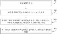
- an embodiment of the present invention provides a method for determining a signal to noise ratio in wireless communication, including: determining an effective signal to noise ratio of a received signal of a current user equipment in a wireless communication; and obtaining for modifying the effective signal to noise ratio At least one parameter; determining a corrected signal to noise ratio corresponding to the at least one parameter and the effective signal to noise ratio based on a mapping relationship for modifying the effective signal to noise ratio.
- a minimum mean square error criterion can be used to determine the effective signal to noise ratio.
- the method for determining the signal to noise ratio in the wireless communication may further correct the effective signal to noise ratio based on one or more parameters, and the corrected corrected signal to noise ratio is more Accurately reflect user equipment Real channel status.
- the mapping relationship for modifying the effective signal to noise ratio is a mapping formula; wherein the at least one parameter and the effective signal to noise The ratio is the input of the mapping formula, and the corrected signal to noise ratio is the output of the mapping formula.
- the mapping relationship for modifying the effective signal to noise ratio is a mapping table, where the mapping table is used to indicate the at least one parameter and The corrected signal to noise ratio corresponding to the effective signal to noise ratio. Since the mapping table includes a series of discrete values, the complexity caused by the calculation using the mapping formula can be simplified by adopting the mapping table.
- the at least one parameter includes the following A combination of one or two: a parameter indicating a receiver algorithm used by the current user equipment, and a parameter of at least one interference signal.
- the at least one parameter includes an indication The parameters of the receiver algorithm used by the current user equipment.
- the multiple iterations can eliminate the effects of multiple interfering
- any one of the at least one interference signal is configured by the current user equipment A neighboring cell of the serving cell is caused by another user equipment in the serving cell, and the other user equipment is a user equipment that is paired with the current user equipment in the serving cell.
- the parameter of any one of the at least one interference signal includes the following a combination of one or more of: a transmission mode of the interfering signal, a rank of the interfering signal, a data to pilot power ratio of the interfering signal, and a modulation scheme of the interfering signal.
- the receiver algorithm is a symbol level interference cancellation algorithm or a maximum likelihood algorithm.
- the correction process refers to the receiver algorithm, and different corrected signal-to-noise ratios can be obtained for different receiver algorithms, so that the calculation result is more accurate.
- the noise ratio determines channel state information; the channel state information is reported to the service site of the current user equipment. Through the method, the accuracy of the channel state information obtained based on the modified signal to noise ratio is further improved, thereby improving the accuracy of channel feedback.
- the wireless communication is a long term evolution wireless communication .
- an embodiment of the present invention provides a device for determining a signal to noise ratio in wireless communication, including: an effective signal to noise ratio determining unit, configured to determine a valid signal of a received signal of a current user equipment in wireless communication. a noise ratio; a parameter determining unit, configured to acquire at least one parameter for correcting the effective signal to noise ratio; and a correcting unit, configured to determine the at least one parameter based on a mapping relationship for modifying the effective signal to noise ratio A corrected signal to noise ratio corresponding to the effective signal to noise ratio.
- the device can be located in the current user device.
- a minimum mean square error criterion can be used to determine the effective signal to noise ratio.
- the mapping relationship for modifying the effective signal to noise ratio is a mapping formula
- the modifying unit calculates the correction by using the mapping formula a signal to noise ratio; wherein the at least one parameter and the effective signal to noise ratio are inputs to the mapping formula, the corrected signal to noise ratio being an output of the mapping formula.
- the mapping relationship for modifying the effective signal to noise ratio is a mapping table, where the mapping table is used to indicate the at least one parameter and And the modified signal-to-noise ratio corresponding to the effective signal-to-noise ratio, wherein the correction unit obtains the corrected signal-to-noise ratio by using the mapping table.
- the at least one parameter includes the following A combination of one or two: a parameter indicating a receiver algorithm used by the current user equipment, and a parameter of at least one interference signal.
- the at least one parameter includes an indication The parameters of the receiver algorithm used by the current user equipment.
- the at least one parameter further includes a parameter of the N interference signals, where N is an integer greater than or equal to 2;
- any one of the at least one interference signal is configured by the current user equipment A neighboring cell of the serving cell is caused by another user equipment in the serving cell, and the other user equipment is a user equipment that is paired with the current user equipment in the serving cell.
- the parameter of any one of the at least one interference signal includes the following a combination of one or more of: a transmission mode of the interfering signal, a rank of the interfering signal, a data to pilot power ratio of the interfering signal, and a modulation scheme of the interfering signal.
- the receiver algorithm is a symbol level interference cancellation algorithm or a maximum likelihood algorithm.
- the ninth possible implementation manner of the second aspect further includes a channel state information reporting unit, And: determining channel state information based on the modified signal to noise ratio, and reporting the channel state information to a service site of the current user equipment.
- the wireless communication is a long term evolution wireless communication .
- an embodiment of the present invention provides a user equipment for determining a signal to noise ratio in wireless communication, including: a memory, configured to store at least one parameter for correcting an effective signal to noise ratio; and a processor, configured to determine the Acquiring the effective signal to noise ratio of the received signal of the user equipment, acquiring the at least one parameter from the memory, determining the at least one parameter and the valid signal based on a mapping relationship for modifying the effective signal to noise ratio The corrected signal to noise ratio corresponding to the noise ratio.
- a minimum mean square error criterion can be used to determine the effective signal to noise ratio.
- the mapping relationship for modifying the effective signal to noise ratio is a mapping formula
- the processor is further configured to use the mapping formula to calculate The modified signal to noise ratio; wherein the at least one parameter and the effective signal to noise ratio are inputs to the mapping formula, the corrected signal to noise ratio being an output of the mapping formula.
- the mapping relationship for modifying the effective signal to noise ratio is a mapping table, where the mapping table is used to indicate the at least one parameter and And the modified signal to noise ratio corresponding to the effective signal to noise ratio, the processor is further configured to obtain the corrected signal to noise ratio by using the mapping table.
- the at least one parameter includes the following A combination of one or two: a parameter indicating a receiver algorithm used by the user equipment, and a parameter of at least one interference signal.
- the at least one parameter includes an indication The parameters of the receiver algorithm used by the user equipment.
- the at least one parameter further includes a parameter of the N interference signals, where N is an integer greater than or equal to 2;
- any one of the at least one interference signal is served by the user equipment Caused by a neighbor cell of a cell, or caused by another user equipment in the serving cell,
- the other user equipment and the user equipment are user equipments that are paired in the serving cell.
- the parameter of any one of the at least one interference signal includes the following a combination of one or more of: a transmission mode of the interfering signal, a rank of the interfering signal, a data to pilot power ratio of the interfering signal, and a modulation scheme of the interfering signal.
- the receiver algorithm is a symbol level interference cancellation algorithm or a maximum likelihood algorithm.
- the processor is further configured to: The modified signal to noise ratio determines channel state information; and reports the channel state information to a service site of the user equipment.
- the modified signal to noise ratio determines channel state information; and reports the channel state information to a service site of the user equipment.
- the step of reporting the channel state information to a serving site of the user equipment may be implemented by a processing unit in the processor, where reporting the channel state information to the The step of the user equipment's service site may be implemented by a radio frequency device in the processor.
- the wireless communication is a long term evolution wireless communication .
- the above embodiment can be used to correct the effective signal-to-noise ratio to obtain a higher accuracy signal-to-noise ratio, thereby facilitating the channel state information with higher accuracy based on the modified signal-to-noise ratio, thereby improving the communication performance of the wireless communication system.
- the above embodiments can be used to improve the traditional minimum mean square error criterion algorithm to achieve better wireless communication effects.
- FIG. 1 is a schematic diagram of a principle of forming an interference signal in wireless communication provided by the prior art
- FIG. 2 is a schematic diagram of a method for determining a signal to noise ratio in wireless communication according to an embodiment of the present invention
- FIG. 3 is a schematic diagram of a schematic structure of a user equipment for determining a signal to noise ratio in wireless communication according to an embodiment of the present invention
- FIG. 4 is a schematic diagram of a method for acquiring a mapping function according to an embodiment of the present invention.
- FIG. 5 is a schematic diagram of a mapping table for determining a signal to noise ratio in wireless communication according to an embodiment of the present invention
- FIG. 6 is a schematic diagram of another mapping table for determining a signal to noise ratio in wireless communication according to an embodiment of the present invention.
- FIG. 7 is a schematic flowchart diagram of correcting an effective signal to noise ratio for multiple interference signals in an iterative manner according to an embodiment of the present invention
- FIG. 8 is a schematic diagram of an apparatus for determining a signal to noise ratio in wireless communication according to an embodiment of the present invention.
- the user equipment that is, the UE, also called the wireless terminal or the user terminal
- the serving station is usually a base station, such as an eNodeB or a NodeB in LTE, or may be an access point for a user equipment to access a mobile communication network, such as a base station controller.
- the serving station may form one or more cells when providing access services for the user equipment, and a cell may geographically cover a certain range and occupy a carrier or frequency band in the frequency domain.
- the user equipment and the service station can implement a communication process by running a wireless communication protocol, including but not limited to LTE, Global System for Mobile (GSM), and Universal Mobile Communication System (Universal Mobile) Telecommunications System (UMTS), Worldwide Interoperability for Microwave Access (WiMAX), Time Division-Synchronous Code Division Multiple Access (TSS) or Code Division Multiple Access 2000 (Code Division) Multiple Access 2000, CDMA2000) and other cellular wireless communication protocols.
- LTE is a more common application scenario.
- the user equipment When the user equipment communicates with the service station, in order to feed back the channel state information to the service station in order to schedule the resource based on the channel state information and allocate the modulation coding scheme and the precoding scheme, the user equipment first needs to accurately estimate the signal to noise ratio of the received signal of the user equipment.
- the signal to noise ratio may also be a Signal to Interference plus Noise Ratio (SINR).
- SINR Signal to Interference plus Noise Ratio
- user equipment 30 may include a memory 31 and a processor 32. Memory 31 and processor 32 may be coupled by a connection line or circuit interface 33.
- the processor 32 in the user device 30 can be used to perform the method of determining the signal to noise ratio in the present embodiment.
- user equipment 30 or processor 32 may determine an effective signal to noise ratio of the received signal of the user equipment 30 in wireless communication based on a minimum mean square error criterion.
- the minimum mean square error criterion is a conventional technique for calculating effective signal-to-noise ratio in wireless communication, and its implementation principle has been in many existing literatures. There is an introduction, which is not described in detail in this embodiment.
- the user equipment 30 acquires at least one parameter for correcting the effective signal to noise ratio.
- the at least one parameter may be a set of parameters, ie a plurality of parameters, which are used to correct the effective signal to noise ratio to obtain a more accurate signal to noise ratio.
- the at least one parameter may be a combination of one or two of: a parameter indicating a receiver algorithm used by the current user equipment 30, and a parameter of at least one interference signal.
- the receiver algorithm may be a symbol level interference cancellation algorithm or a maximum likelihood algorithm, and of course other available receiver algorithms are not excluded, and the algorithm used is used to achieve good interference suppression in the demodulation of the received signal.
- the parameter indicating the receiver algorithm is used as a reference factor to modify the signal to noise ratio, which indicates that the user equipment 30 adopting different receiver algorithms has different suppression capabilities for interference, and the modification can improve the information obtained by the user equipment 30.
- the accuracy of the noise ratio is used as a reference factor to modify the signal to noise ratio, which indicates that the user equipment 30 adopting different receiver algorithms has different suppression capabilities for interference, and the modification can improve the information obtained by the user equipment 30. The accuracy of the noise ratio.
- At least one parameter may be stored in a memory 31 in the user device 30.
- the memory 31 may be a random access memory (RAM), a read-only memory (ROM), a flash memory, or the like, or may be a buffer (Buffer) or a FIFO (First In First Out,
- the type of the memory 31 is not limited to the type of the memory 31, such as a first-in first-out queue or a register or the like for temporary or temporary storage.
- memory 31 can be a register.
- the processor 32 may specifically acquire the at least one parameter from the memory 31 when performing a correction process.
- the user device 30 updates the memory 31 according to the operating state of the user device 30 in real time or after a certain time interval during operation.
- processor 32 may be aware of the receiver algorithm currently being used by user equipment 30 and write parameters indicative of the algorithm to memory 31 for subsequent correction processing.
- user equipment 30 may receive parameters of at least one interference signal from its serving base station or other network communication node and write it to memory 31 for subsequent use in the correction process.
- the parameters of the interference signal may include a transmission mode of the interference signal, a rank of the interference signal, a data to pilot power ratio of the interference signal, or a modulation scheme of the interference signal.
- the user equipment 30 uses the parameters of the interference signal as a reference factor to correct the signal to noise ratio.
- the interference caused by the user equipment 30 is different when the transmission mode, the rank or the modulation scheme used by the scrambling signal is different, and the accuracy of the signal to noise ratio calculated by the user equipment 30 can be improved by using the correction.
- An interference signal may be caused by a user equipment that is paired with the user equipment 30 in the serving cell of the current serving base station of the user equipment 30, or is caused by a neighboring cell of the neighboring base station. This embodiment does not specifically limit the cause of the interference signal.
- the transmission mode of the interference signal may be a MIMO transmission mode of an interference signal from an interfering cell, and may include a MIMO transmission mode such as transmit diversity, open-loop space division multiplexing, closed-loop space division multiplexing, or beamforming.
- the modulation scheme of the interference signal may include 16QAM (Quadrature Amplitude Modulation), 64QAM or QPSK (Quadrature Phase Shift Keying), and the like.
- the data-to-pilot power ratio of the interfering signal reflects the ratio of the data signal power to the pilot power in the interfering signal, wherein the pilot, which may also be referred to as a reference signal, may be used for channel estimation or measurement.
- these parameters may be obtained by the user equipment estimating the interference signal based on the existing interference estimation scheme. That is, prior to S22, user equipment 30 or its processor 32 may obtain parameters of the at least one interfering signal by estimating an interfering signal or interfering cell.
- this embodiment does not exclude other ways in which the user equipment 30 acquires parameters of at least one interference signal, such as the user equipment 30 may obtain these parameters from other communication nodes, such as a base station or other user equipment.
- user equipment 30 may receive parameters of at least one interference signal specifically through a physical downlink control channel (PDCCH) of the serving base station.
- PDCCH physical downlink control channel
- the user equipment 30 determines a corrected signal to noise ratio corresponding to the at least one parameter and the effective signal to noise ratio based on a mapping relationship for correcting the effective signal to noise ratio. Specifically, processing The device 32 can obtain the corrected signal to noise ratio using a manner based on the calculation of the mapping formula or a way of looking up the mapping table.
- SNR is the obtained corrected signal to noise ratio
- SNR no is the effective signal to noise ratio
- ⁇ is a parameter set including the at least one parameter.
- f() is a mapping function that represents the mapping relationship.
- the mapping function f() may be preset, which may be stored in the memory 31 or in another memory. That is to say, f() can be obtained by offline.
- f() can be obtained by a person skilled in the art based on the simulation. Before the user equipment 30 leaves the factory, the f() is stored in the memory 31 or in another memory as a parameter in the form of software code, and the processor 32 can acquire the f() from the memory 31 or another memory. And based on the f () to do correction processing to obtain a modified signal to noise ratio. Alternatively, f() may also be placed into processor 32 as a hardware circuit, i.e., in processor 32 by an integrated circuit or other circuit fabrication process.
- the processor 32 can directly calculate the corrected signal to noise ratio based on f().
- the value of the corrected signal-to-noise ratio obtained by the user equipment 30 or the processor 32 is different through the f() mapping, thereby realizing the modification and improvement of the obtained signal according to the parameters of the actual receiver.
- the noise ratio improves the accuracy of the obtained signal-to-noise ratio.
- f() is pre-stored in the memory 31 or in another memory in software form or built into the processor 32 as a hardware circuit, those skilled in the art can pass simulation and verification in the development or production verification of the user device 30. Get the appropriate function f().
- the expression of f() can be replaced with a lookup table or a mapping table that includes a plurality of discrete values.
- the mapping table is configured to indicate a modified signal to noise ratio corresponding to the at least one parameter and the effective signal to noise ratio, and implements the mapping relationship mentioned earlier in this embodiment instead of f().
- the processor 32 is configured to obtain a corrected signal to noise ratio by looking up the mapping table by taking one or more parameters as inputs.
- the mapping table may be stored in the memory 31 or in another memory in the form of software code, which is read by the processor 32 from the memory 31. Or alternatively, the mapping table can be embedded within processor 32 in the form of logic circuitry. While the processor 32 is performing the correction process, since the processor 32 already has the mapping table built in, the processor 32 can directly calculate the corrected signal to noise ratio based on the logic circuit reflecting the mapping table.
- FIG. 5 is a schematic diagram of a mapping table 1 according to an embodiment of the present invention.
- the parameters indicating the receiver algorithm are taken as input 1 of Table 1, which includes a series of discrete values, such as Algorithm 1, Algorithm 2, and the like.
- the other input 2 is the effective signal to noise ratio, including multiple values, which are respectively expressed as effective signal to noise ratio 1, effective signal to noise ratio 2, and so on.
- the mapping table 1 at this time is equivalent to a two-dimensional lookup table, that is, one correction result is mapped by two inputs.
- the processor 32 finds the corresponding correction result as the corrected signal to noise ratio in Table 2 by taking the parameters of the acquired receiver algorithm and the effective signal to noise ratio as two inputs. For example, algorithm 1 and effective signal to noise ratio 1 correspond to correction result 1, and algorithm 2, effective signal to noise ratio 2 corresponds to correction result x+1.
- mapping table 2 in addition to the effective signal to noise ratio and the parameter indicating the receiver algorithm as two inputs, three inputs, that is, the transmission mode of the interference signal and the rank of the interference signal, may be further introduced. Or a modulation scheme of the interference signal.
- Table 2 can be considered as a five-dimensional lookup table, including five inputs, namely the effective signal-to-noise ratio and four parameters in the parameter set ⁇ , which are parameters of the receiver algorithm and interference signals, respectively. a transmission mode, a rank of the interference signal, and a modulation scheme of the interference signal.
- the processor 32 finds the corresponding correction result in the lookup table 2 through the five inputs as the corrected signal to noise ratio.
- a plurality of mapping tables may be built in the user equipment 30, and the plurality of mapping tables may be stored in the memory 31 or in another memory in the form of software code, or directly embedded in the processor 32 in the form of logic circuits, the user Device 30 or processor 32 may decide which mapping table to use in the plurality of mapping tables to determine the corrected signal to noise ratio.
- the input to each mapping table can be two Or more, the number of inputs depends on which parameters are included in the parameter set ⁇ involved in the mapping table. In addition to the one or more parameters listed in Table 2, these parameters may further include other parameters that affect the interference characteristics, which is not limited in this embodiment. The greater the number of parameters used, the more factors are considered in the correction process, and the corrected signal-to-noise ratio is more accurate. Therefore, as the number of inputs to the mapping table increases, the correction effect will increase.
- the number of interference signals is one or more depending on the actual usage scenario of the user equipment 30 or the wireless network deployment around the user equipment 30.
- the effective signal to noise ratio can be corrected for each interference signal in sequence.
- the user equipment 30 or the processor 32 may have the ability to process multiple interfering signals. Specifically, user equipment 30 first calculates the effective signal to noise ratio before correction and then traverses all possible interference signals. If it is necessary to perform correction processing for the i-th interfering signal, the i-th corrected signal-to-noise ratio is calculated using the mapping table or mapping formula described in the previous embodiment.
- the i-th corrected signal-to-noise ratio is used as an input for the next one, i.e., the i+1th interference signal, for correction.
- i is an integer greater than or equal to 1 and less than or equal to N
- the initial value of i is 1.
- the value of i is incremented by one after each iteration until i equals N.
- N is the number of interference signals and is an integer greater than or equal to 2. That is, the processor 32 may calculate an effective signal to noise ratio for each interfering signal parameter in an iterative manner to improve system performance.
- the processor 32 performs a modified effective signal to noise ratio for the i-th interfering signal based on the mapping relationship, that is, the processor 32 determines and determines a receiver algorithm used by the current user equipment based on the mapping table or mapping formula.
- the embodiment can further improve the accuracy of the calculated signal to noise ratio.
- the method for determining a signal to noise ratio may further include: in S24, the user equipment 30 or The processor 32 may determine the channel state information based on the calculated corrected signal to noise ratio, and report the channel state information to the service site of the current user equipment 30.
- the embodiment is equivalent to providing a channel state information reporting or channel feedback method.
- the processor 32 can be further divided into a processing unit for determining channel state information and a radio frequency device (not shown in FIG. 3) for reporting the channel state information.
- the radio frequency device may be located in the same chip as the processing unit or in different chips.
- the channel state information in this embodiment may include at least one of a Rank Index (RI), a Pre-coder Matrix Indicator (PMI), or a Channel Quality Indicator (CQI). .
- the CQI may further include a wideband CQI or a narrowband CQI
- the PMI may further include a wideband PMI or a narrowband PMI, which is not limited in this embodiment. Since the channel state information is obtained based on the corrected signal to noise ratio, it is more accurate to accurately reflect the actual state of the channel used by the user equipment 30 in the wireless communication.
- the scheduling of the serving base station based on the channel state information fed back by the user equipment 30 is also more accurate, improving the data throughput of the user equipment 30, thereby improving the overall performance of the wireless communication system.
- processor 32 may specifically be a communications processor, baseband and radio frequency processor, general purpose processing unit or wireless modem that can be used to operate any wireless communication protocol such as LTE, UMTS or GSM.
- the processor 32 can operate under the drive of the necessary driver software.
- the driver software can be stored in memory 31 or in other storage units.
- the driver software may be the necessary protocol software to run the wireless communication protocol described above.
- Processor 32 may include one or more chips, or processor 32 may be implemented by an integrated circuit or other form of circuitry, such as a printed circuit, or a combination of both.
- the integrated circuit is in the form of a circuit fabricated on a semiconductor substrate by an integrated circuit process, and may include at least one of a digital circuit or an analog circuit.
- a chip is a component that includes a large number of integrated circuits and peripheral packages.
- a person skilled in the art can obtain the mapping relationship mentioned in this embodiment in the manner shown in FIG. 4 in the development or production verification of the user equipment 30.
- One skilled in the art can construct a conventional receiver emulation program 401 and an improved receiver emulation program 402 through a computer simulation environment.
- the conventional receiver emulation program 401 is used to simulate the signal to noise ratio calculation method in the receiver in the prior art
- the improved receiver emulation program is used to simulate the method provided by the embodiment of the present invention.
- a set of identical parameters ⁇ as described in the previous embodiment can be set for the two sets of programs 401 and 402.
- the initial signal-to-noise ratio of the conventional receiver emulation program 401 is set to a value such that the reception accuracy of the conventional receiver emulation program 401 is lower than this signal-to-noise ratio value, If the frame error rate reaches the preset value, such as 10%.
- the improved receiver emulation program 402 all possible SNR values are traversed and these values are sequentially configured to the improved receiver emulation program 402, and the improved receiver emulation program 402 receives the accuracy for each SNR value, such as Frame error rate.
- the SNR value of the input improved receiver emulation program 402 at this time is the SNR no under the set of parameters ⁇ Corrected value. That is to say, for different sets of parameters ⁇ , the correspondence between the values of the plurality of discrete SNR no and the plurality of discrete SNR values can be obtained by the above manner, thereby forming the mapping table described earlier. As described above, the mapping table reflecting the correspondence between the plurality of discrete values can also be converted into an f() function, that is, a person skilled in the art can select an appropriate f() function by a function fitting method to simulate the actual Correspondence between multiple discrete values. There are already quite common applications in the field of mathematics and computers for how to perform such fitting, and will not be described in detail here.
- FIG. 8 is a schematic diagram of an apparatus 80 for determining a signal to noise ratio in wireless communication according to an embodiment of the present invention, which may be located inside a user equipment for implementing correction of an effective signal to noise ratio.
- the apparatus 80 may include: an effective signal to noise ratio determining unit 81, configured to determine an effective signal to noise ratio of a received signal of a current user equipment in the wireless communication based on a minimum mean square error criterion; and a parameter determining unit 82 configured to acquire the corrected information Determining at least one parameter of an effective signal to noise ratio; the correcting unit 83, configured to determine a modified letter corresponding to the at least one parameter and the effective signal to noise ratio based on a mapping relationship for modifying the effective signal to noise ratio Noise ratio.
- the apparatus 80 may further include: a channel state information reporting unit 84, configured to determine channel state information based on the modified signal to noise ratio, and report the channel state information to the The service site of the current user device.
- a channel state information reporting unit 84 configured to determine channel state information based on the modified signal to noise ratio, and report the channel state information to the The service site of the current user device.
- the computer readable storage medium may be a magnetic disk, an optical disk, a ROM, a RAM, or the like.
Landscapes
- Engineering & Computer Science (AREA)
- Computer Networks & Wireless Communication (AREA)
- Signal Processing (AREA)
- Physics & Mathematics (AREA)
- Electromagnetism (AREA)
- Quality & Reliability (AREA)
- Noise Elimination (AREA)
Abstract
L'invention concerne un procédé et un appareil de détermination d'un rapport signal sur bruit pendant une communication sans fil, et se rapporte au domaine des communications sans fil. Le procédé comprend : la détermination d'un rapport signal sur bruit effectif d'un signal de réception actuel d'UE pendant une communication sans fil ; l'acquisition d'au moins un paramètre destiné à modifier le rapport signal sur bruit effectif ; sur la base d'une relation de mappage utilisée pour modifier le rapport signal sur bruit effectif, la détermination d'un rapport signal sur bruit modifié qui correspond à l'au moins un paramètre et au rapport signal sur bruit effectif.
Priority Applications (4)
| Application Number | Priority Date | Filing Date | Title |
|---|---|---|---|
| CN201580011219.4A CN106170936B (zh) | 2015-06-27 | 2015-06-27 | 无线通信中确定信噪比的方法和装置 |
| EP15884171.8A EP3136808A4 (fr) | 2015-06-27 | 2015-06-27 | Procédé et appareil de détermination d'un rapport signal sur bruit pendant une communication sans fil |
| PCT/CN2015/082582 WO2017000095A1 (fr) | 2015-06-27 | 2015-06-27 | Procédé et appareil de détermination d'un rapport signal sur bruit pendant une communication sans fil |
| US15/667,192 US10477431B2 (en) | 2015-06-27 | 2017-08-02 | Method and apparatus for determining signal-to-noise ratio in wireless communication |
Applications Claiming Priority (1)
| Application Number | Priority Date | Filing Date | Title |
|---|---|---|---|
| PCT/CN2015/082582 WO2017000095A1 (fr) | 2015-06-27 | 2015-06-27 | Procédé et appareil de détermination d'un rapport signal sur bruit pendant une communication sans fil |
Related Child Applications (1)
| Application Number | Title | Priority Date | Filing Date |
|---|---|---|---|
| US15/667,192 Continuation US10477431B2 (en) | 2015-06-27 | 2017-08-02 | Method and apparatus for determining signal-to-noise ratio in wireless communication |
Publications (1)
| Publication Number | Publication Date |
|---|---|
| WO2017000095A1 true WO2017000095A1 (fr) | 2017-01-05 |
Family
ID=57359361
Family Applications (1)
| Application Number | Title | Priority Date | Filing Date |
|---|---|---|---|
| PCT/CN2015/082582 Ceased WO2017000095A1 (fr) | 2015-06-27 | 2015-06-27 | Procédé et appareil de détermination d'un rapport signal sur bruit pendant une communication sans fil |
Country Status (4)
| Country | Link |
|---|---|
| US (1) | US10477431B2 (fr) |
| EP (1) | EP3136808A4 (fr) |
| CN (1) | CN106170936B (fr) |
| WO (1) | WO2017000095A1 (fr) |
Families Citing this family (6)
| Publication number | Priority date | Publication date | Assignee | Title |
|---|---|---|---|---|
| EP3535937B1 (fr) * | 2016-12-02 | 2021-08-25 | Huawei Technologies Duesseldorf GmbH | Technique de transmission basée sur la sélection de numérologie |
| CN108243449B (zh) * | 2016-12-27 | 2021-04-27 | 中国移动通信集团浙江有限公司 | 一种用户终端分组调度方法及装置 |
| US10677402B2 (en) * | 2017-10-04 | 2020-06-09 | Resilience Magnum IP, LLC | Lighting drywall |
| CN110620649A (zh) * | 2019-06-20 | 2019-12-27 | 南京铁道职业技术学院 | 铁道供电系统及其方法 |
| CN113572550B (zh) * | 2021-07-23 | 2023-08-01 | Oppo广东移动通信有限公司 | 确定信号的信噪比的方法、装置、计算机设备及存储介质 |
| CN120150771B (zh) * | 2025-02-26 | 2026-02-24 | 东南大学 | 一种保障服务质量的低复杂度mimo预编码设计方法 |
Citations (3)
| Publication number | Priority date | Publication date | Assignee | Title |
|---|---|---|---|---|
| CN101640572A (zh) * | 2008-07-18 | 2010-02-03 | 俊茂微电子(上海)有限公司 | 信噪比测量方法和装置以及通信设备 |
| CN102457337A (zh) * | 2010-10-25 | 2012-05-16 | 索尼公司 | 接收设备与方法、解调设备与方法、以及程序 |
| WO2013154472A1 (fr) * | 2012-04-11 | 2013-10-17 | Telefonaktiebolaget L M Ericsson (Publ) | Station de base radio de faible puissance et son procédé pour planifier des transmissions en liaison descendante à un équipement utilisateur |
Family Cites Families (14)
| Publication number | Priority date | Publication date | Assignee | Title |
|---|---|---|---|---|
| US6292519B1 (en) * | 1998-03-11 | 2001-09-18 | Telefonaktiebolaget Lm Ericsson (Publ) | Correction of signal-to-interference ratio measurements |
| US7215930B2 (en) * | 2003-03-06 | 2007-05-08 | Qualcomm, Incorporated | Method and apparatus for providing uplink signal-to-noise ratio (SNR) estimation in a wireless communication |
| US20050272373A1 (en) * | 2003-06-04 | 2005-12-08 | Matsushita Electric Industrial Co., Ltd | Sir measurement device and sir measurement method |
| CN101599788B (zh) * | 2009-05-15 | 2013-02-13 | 华为技术有限公司 | Lte系统中确定信道反馈信息的方法及装置 |
| US8644262B1 (en) * | 2010-05-20 | 2014-02-04 | Marvell International Ltd. | Method and apparatus for estimating a channel quality indicator (CQI) for multiple input multiple output (MIMO) systems |
| TW201238260A (en) * | 2011-01-05 | 2012-09-16 | Nec Casio Mobile Comm Ltd | Receiver, reception method, and computer program |
| CN102395187B (zh) * | 2011-11-01 | 2014-07-30 | 新邮通信设备有限公司 | 物理混合重传指示信道的功率配置方法 |
| US8761039B2 (en) | 2012-03-28 | 2014-06-24 | Apple Inc. | Adaptive generation of channel quality indicators (CQIs) based on a current communication scenario |
| US8953726B2 (en) * | 2012-06-01 | 2015-02-10 | Qualcomm Incorporated | Antenna selection technique for fast diversity |
| US9503216B2 (en) * | 2012-11-02 | 2016-11-22 | Telefonaktiebolaget L M Ericsson (Publ) | Methods and devices related to effective measurements |
| US9451625B2 (en) * | 2013-09-19 | 2016-09-20 | Telefonaktiebolaget Lm Ericsson (Publ) | System and method for providing interference characteristics for interference mitigation |
| US9673957B2 (en) * | 2013-09-19 | 2017-06-06 | Telefonaktiebolaget Lm Ericsson (Publ) | System and method for providing interference characteristics for interference mitigation |
| US10003486B2 (en) * | 2014-04-28 | 2018-06-19 | Intel IP Corporation | Non-orthogonal multiple access (NOMA) wireless systems and methods |
| CN103997473B (zh) * | 2014-05-13 | 2017-10-17 | 华为技术有限公司 | 一种信号干扰的滤波方法及相关装置 |
-
2015
- 2015-06-27 EP EP15884171.8A patent/EP3136808A4/fr not_active Withdrawn
- 2015-06-27 WO PCT/CN2015/082582 patent/WO2017000095A1/fr not_active Ceased
- 2015-06-27 CN CN201580011219.4A patent/CN106170936B/zh active Active
-
2017
- 2017-08-02 US US15/667,192 patent/US10477431B2/en active Active
Patent Citations (3)
| Publication number | Priority date | Publication date | Assignee | Title |
|---|---|---|---|---|
| CN101640572A (zh) * | 2008-07-18 | 2010-02-03 | 俊茂微电子(上海)有限公司 | 信噪比测量方法和装置以及通信设备 |
| CN102457337A (zh) * | 2010-10-25 | 2012-05-16 | 索尼公司 | 接收设备与方法、解调设备与方法、以及程序 |
| WO2013154472A1 (fr) * | 2012-04-11 | 2013-10-17 | Telefonaktiebolaget L M Ericsson (Publ) | Station de base radio de faible puissance et son procédé pour planifier des transmissions en liaison descendante à un équipement utilisateur |
Non-Patent Citations (1)
| Title |
|---|
| See also references of EP3136808A4 * |
Also Published As
| Publication number | Publication date |
|---|---|
| US20170347289A1 (en) | 2017-11-30 |
| US10477431B2 (en) | 2019-11-12 |
| EP3136808A4 (fr) | 2017-06-07 |
| EP3136808A1 (fr) | 2017-03-01 |
| CN106170936B (zh) | 2019-07-12 |
| CN106170936A (zh) | 2016-11-30 |
Similar Documents
| Publication | Publication Date | Title |
|---|---|---|
| RU2629944C2 (ru) | Способы и конструкции для передачи отчетов с csi | |
| US8825069B2 (en) | Methods, apparatus and computer programs for configuring user equipment | |
| CN106464322B (zh) | 小区内干扰消除以及抑制的信令的方法以及用户设备 | |
| US8432873B2 (en) | Method and apparatus for computing and reporting channel quality indication (CQI) | |
| WO2021007768A1 (fr) | Gestion de ressources permettant de rapporter un rapport signal sur brouillage plus bruit | |
| US10477431B2 (en) | Method and apparatus for determining signal-to-noise ratio in wireless communication | |
| US20240396664A1 (en) | Modulation and coding scheme reception | |
| US9520963B2 (en) | Modulation and coding scheme selection for link adaptation | |
| CN102726016B (zh) | 用于无线通信系统中信道估计的设备和方法 | |
| CN102550106A (zh) | 小区间干扰协调的系统和方法 | |
| TWI559696B (zh) | 無線通信系統內之方法及配置 | |
| EP3047590A1 (fr) | Système et procédé de fourniture de caractéristiques de brouillage pour atténuer un brouillage | |
| US10044425B2 (en) | Multi-layer wireless streaming with adaptive constellation mapping (ACM) | |
| EP3796569B1 (fr) | Procédé de communication, dispositif terminal, et dispositif de réseau | |
| US9674002B2 (en) | Channel estimation in a multi-antenna wireless communications system | |
| WO2019242898A1 (fr) | Technique de sélection d'un format de transport mimo | |
| JP5487090B2 (ja) | 無線信号処理方法および無線通信装置 | |
| US20080084829A1 (en) | Apparatus, method and computer program product providing link adaptation | |
| JP5551810B1 (ja) | 無線通信装置及び無線伝送システム | |
| US10448407B2 (en) | Interference cancellation enhancement in HetNets through coordinated SIMO/MIMO interference codes | |
| EP4686302A1 (fr) | Procédé et appareil de communication sans fil | |
| CN107534530B (zh) | 信干噪比的计算方法、装置和接收机 | |
| GB2640726A (en) | Method, apparatus and computer program | |
| GB2640727A (en) | Method, apparatus and computer program | |
| EP4364365A1 (fr) | Procédé de détermination de pondérations de récepteurs |
Legal Events
| Date | Code | Title | Description |
|---|---|---|---|
| REEP | Request for entry into the european phase |
Ref document number: 2015884171 Country of ref document: EP |
|
| WWE | Wipo information: entry into national phase |
Ref document number: 2015884171 Country of ref document: EP |
|
| 121 | Ep: the epo has been informed by wipo that ep was designated in this application |
Ref document number: 15884171 Country of ref document: EP Kind code of ref document: A1 |
|
| NENP | Non-entry into the national phase |
Ref country code: DE |