WO2017002208A1 - Système de robot - Google Patents
Système de robot Download PDFInfo
- Publication number
- WO2017002208A1 WO2017002208A1 PCT/JP2015/068890 JP2015068890W WO2017002208A1 WO 2017002208 A1 WO2017002208 A1 WO 2017002208A1 JP 2015068890 W JP2015068890 W JP 2015068890W WO 2017002208 A1 WO2017002208 A1 WO 2017002208A1
- Authority
- WO
- WIPO (PCT)
- Prior art keywords
- axis
- arm
- redundant
- robot
- posture
- Prior art date
- Legal status (The legal status is an assumption and is not a legal conclusion. Google has not performed a legal analysis and makes no representation as to the accuracy of the status listed.)
- Ceased
Links
Images


Classifications
-
- B—PERFORMING OPERATIONS; TRANSPORTING
- B25—HAND TOOLS; PORTABLE POWER-DRIVEN TOOLS; MANIPULATORS
- B25J—MANIPULATORS; CHAMBERS PROVIDED WITH MANIPULATION DEVICES
- B25J9/00—Program-controlled manipulators
- B25J9/02—Program-controlled manipulators characterised by movement of the arms, e.g. cartesian coordinate type
- B25J9/04—Program-controlled manipulators characterised by movement of the arms, e.g. cartesian coordinate type by rotating at least one arm, excluding the head movement itself, e.g. cylindrical coordinate type or polar coordinate type
- B25J9/046—Revolute coordinate type
- B25J9/047—Revolute coordinate type the pivoting axis of the first arm being offset to the vertical axis
-
- B—PERFORMING OPERATIONS; TRANSPORTING
- B25—HAND TOOLS; PORTABLE POWER-DRIVEN TOOLS; MANIPULATORS
- B25J—MANIPULATORS; CHAMBERS PROVIDED WITH MANIPULATION DEVICES
- B25J9/00—Program-controlled manipulators
- B25J9/16—Program controls
- B25J9/1674—Program controls characterised by safety, monitoring, diagnostic
- B25J9/1676—Avoiding collision or forbidden zones
-
- B—PERFORMING OPERATIONS; TRANSPORTING
- B25—HAND TOOLS; PORTABLE POWER-DRIVEN TOOLS; MANIPULATORS
- B25J—MANIPULATORS; CHAMBERS PROVIDED WITH MANIPULATION DEVICES
- B25J9/00—Program-controlled manipulators
- B25J9/06—Program-controlled manipulators characterised by multi-articulated arms
-
- B—PERFORMING OPERATIONS; TRANSPORTING
- B25—HAND TOOLS; PORTABLE POWER-DRIVEN TOOLS; MANIPULATORS
- B25J—MANIPULATORS; CHAMBERS PROVIDED WITH MANIPULATION DEVICES
- B25J9/00—Program-controlled manipulators
- B25J9/16—Program controls
- B25J9/1628—Program controls characterised by the control loop
- B25J9/1643—Program controls characterised by the control loop redundant control
-
- G—PHYSICS
- G05—CONTROLLING; REGULATING
- G05B—CONTROL OR REGULATING SYSTEMS IN GENERAL; FUNCTIONAL ELEMENTS OF SUCH SYSTEMS; MONITORING OR TESTING ARRANGEMENTS FOR SUCH SYSTEMS OR ELEMENTS
- G05B2219/00—Program-control systems
- G05B2219/30—Nc systems
- G05B2219/39—Robotics, robotics to robotics hand
- G05B2219/39082—Collision, real time collision avoidance
Definitions
- the disclosed embodiment relates to a robot system.
- robots that operate by driving a plurality of joints are known.
- An end effector suitable for applications such as welding and gripping is attached to the tip of such a robot, and various operations such as workpiece processing and movement are performed.
- the robot arm (hereinafter simply referred to as “arm”) may interfere with equipment other than the robot or the robot body, and the operation range of the robot may be substantially narrowed.
- the opening and the arm cannot be avoided when the tip of the robot is inserted into a place where the opening is narrow and deep.
- One aspect of the embodiment has been made in view of the above, and an object thereof is to provide a robot system that can reduce arm interference.
- a robot system includes a base, a turning base, a first arm, a redundant arm, a second arm, a robot including a third arm, and an operation control unit.
- the base is fixed to the installation surface.
- the swivel base is supported by the base so as to be rotatable about a first axis in the vertical direction.
- the base end side of the first arm is supported by the turning base so that the first arm can turn around a horizontal second axis.
- the redundant arm is supported on the distal end side of the first arm so that the redundant arm can turn around a redundant axis parallel to the second axis.
- the second arm is supported on the distal end side of the redundant arm so that the second arm can pivot about a third axis parallel to the second axis.
- the third arm is supported on the distal end side of the second arm so that the third arm can rotate about a fourth axis perpendicular to the third axis.
- the operation control unit operates the redundant arm so that a control point provided on the fourth axis moves linearly while maintaining the direction of the fourth axis.
- a robot system capable of reducing arm interference can be provided.
- FIG. 1 is a schematic diagram illustrating an outline of a robot according to an embodiment.
- FIG. 2 is a side view of the robot.
- FIG. 3 is a block diagram showing the configuration of the robot system.
- FIG. 4A is a schematic diagram (part 1) illustrating an operation of linearly moving the control point while maintaining the direction of the fourth axis.
- FIG. 4B is a schematic diagram (part 2) illustrating an operation of linearly moving the control point while maintaining the direction of the fourth axis.
- FIG. 4C is a schematic diagram (part 3) illustrating an operation of linearly moving the control point while maintaining the direction of the fourth axis.
- FIG. 5A is a schematic diagram (part 1) illustrating an operation when a redundant shaft protrudes toward the third arm.
- FIG. 1 is a schematic diagram illustrating an operation when a redundant shaft protrudes toward the third arm.
- FIG. 5B is a schematic diagram (part 2) illustrating the operation when the redundant shaft protrudes toward the third arm.
- FIG. 5C is a schematic diagram (part 3) illustrating the operation when the redundant shaft protrudes toward the third arm.
- FIG. 6A is a schematic diagram (part 1) illustrating an operation of moving a control point in a direction perpendicular to the fourth axis.
- FIG. 6B is a schematic diagram (part 2) illustrating an operation of moving the control point in a direction perpendicular to the fourth axis.
- FIG. 6C is a schematic diagram (part 3) illustrating the operation of moving the control point in a direction perpendicular to the fourth axis.
- FIG. 6A is a schematic diagram (part 1) illustrating an operation of moving a control point in a direction perpendicular to the fourth axis.
- FIG. 6B is a schematic diagram (part 2) illustrating an operation of moving the control point in a direction perpendicular to the fourth axis.
- FIG. 7A is a schematic diagram (part 1) illustrating an operation of moving a control point along a fourth axis in a vertical direction.
- FIG. 7B is a schematic diagram (part 2) illustrating the operation of moving the control point along the fourth axis in the vertical direction.
- FIG. 7C is a schematic diagram (part 3) illustrating the operation of moving the control point along the fourth axis in the vertical direction.
- FIG. 8 is a diagram for explaining singularity avoidance of the third arm.
- FIG. 9 is a flowchart showing a processing procedure executed by the robot control apparatus.
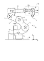
- FIG. 1 is a schematic diagram showing an outline of the robot 10.
- FIG. 1 only a part of the configuration of the robot 10 is shown, and details will be described later with reference to FIG.
- FIG. 1 also shows a three-dimensional orthogonal coordinate system including the Z axis whose vertical upward direction is the positive direction for easy understanding. Such an orthogonal coordinate system may be shown in other drawings used in the following description.
- the robot 10 includes joint portions corresponding to the first axis S, the second axis L, the redundant axis E, the third axis U, the fourth axis R, the fifth axis B, and the sixth axis T, respectively. have.
- the robot 10 changes its posture by turning or rotating each arm by a motor 10a (see FIG. 3) that is an actuator that drives each joint.
- the robot 10 is a seven-axis robot having a redundant axis E.
- first axis S “second axis L”, “redundant axis E”, “third axis U”, “fourth axis R”, “fifth axis” which are the rotation axes of the joint portions.
- Axis B” and “sixth axis T” may be used as names of corresponding joint portions.
- joints having rotation axes that change the angle formed by adjacent arms are “swivel joints”.
- the second axis L, the redundant axis E, and the third axis U do not include a rotating joint in the middle, and are therefore always parallel to each other.
- each joint portion of the robot 10 is symbolized, and the above-described “rotary joint” is represented by a rhombus and the above-mentioned “swivel joint” is represented by a circle.
- the line connecting the diagonal lines of the diamond symbol corresponding to the “rotary joint” corresponds to the rotation surface of the joint, and the joint rotates around the rotation axis perpendicular to the line.
- the point attached to the center of the circle corresponding to the “swivel joint” corresponds to the rotation axis, and the joint rotates around the rotation axis.
- the robot 10 includes a first arm 13 that turns around the second axis L, a redundant arm 14 that turns around the redundant axis E, and a second arm 15 that turns around the third axis U.
- a third arm 16 having a fourth axis R, a fifth axis B, and a sixth axis T is provided on the distal end side of the second arm 15.
- the control point 20 is set on the fourth axis R.
- the control point 20 refers to a reference point when the robot 10 is controlled.
- control point 20 is shown between the joint corresponding to the fourth axis R and the joint corresponding to the fifth axis B, but any position on the fourth axis R is possible.
- the control point 20 can be set to For example, the control point 20 can be set at the intersection of the fourth axis R and the fifth axis B.
- 6-axis robots that do not have the redundant axis E and the redundant arm 14 described above have been widely used.
- the third axis U is disposed on the distal end side of the first arm 13, and the second arm 15 turns around the third axis U.
- the third axis U moves along a circle centered on the second axis L. Therefore, the direction parallel to the X axis (horizontal direction) in FIG. The third axis U cannot be moved along the parallel direction (vertical direction).
- the third axis U can be moved in the horizontal direction or the vertical direction by using a seven-axis robot including the redundant axis E and the redundant arm 14 described above. Therefore, according to the robot 10, the control point 20 provided on the fourth axis R can be linearly moved while maintaining the direction of the fourth axis R on the tip side with respect to the third axis U.
- the redundant axis E on the distal end side of the first arm 13 is movable on a locus EL indicated by a circle in FIG.
- the trajectory EL is shown as a circle in FIG. 1, since it includes rotation around the first axis S, it is actually spherical.
- the third axis U on the distal end side of the redundant arm 14 can move on the locus UL indicated by a circle when the redundant axis E exists at the position shown in FIG.
- the range through which the locus UL passes is the entire area within the movable range UN shown in the figure. That is, the third axis U can move to any position within the movable range UN.
- the movable range UN is shown as a circle in FIG. 1, since it includes rotation around the first axis S, it is actually spherical. In the above description, interference between the arms of the robot 10 and interference with the ground plane 30 are ignored for easy understanding.
- shaft U in the base end side (the front end side of the redundant arm 14) of the 2nd arm 15 can be moved to the arbitrary positions of the movable range UN. Therefore, the third axis U can be moved along an arbitrary straight line within the movable range UN. Furthermore, since the second arm 15 is rotatable around the third axis U, the direction of the fourth axis R in the third arm 16 attached to the distal end side of the second arm 15 can be freely changed.
- the control point 20 provided on the fourth axis R is maintained while maintaining the direction of the fourth axis R. It can be moved linearly. Details of the specific operation of the robot 10 for linearly moving the control point 20 will be described later with reference to FIGS. 4A to 4C, FIGS. 5A to 5C, FIGS. 6A to 6C, and FIGS. 7A to 7C. .
- FIG. 2 is a side view of the robot 10.
- the robot 10 includes a base 11, a turning base 12, a first arm 13, a redundant arm 14, a second arm 15, and a third arm 16 from the base end side toward the tip end side.
- the third arm 16 includes a rotation arm 16a, a turning arm 16b, and a rotation arm 16c from the proximal end side toward the distal end side.
- the base 11 is fixed to an installation surface 30 such as a floor.
- the turning base 12 is supported by the base 11 so as to be rotatable about the first axis S in the vertical direction.
- the first arm 13 is supported by the turning base 12 so as to be turnable around a second axis L whose base end side is horizontal.
- the redundant arm 14 is supported on the distal end side of the first arm 13 so that the base end side can turn around the redundant axis E parallel to the second axis L.
- the redundant axis E which is the rotation axis of the redundant arm 14 projects in the positive X-axis direction in the posture of FIG.
- a posture and a posture of projecting in the negative X-axis direction can be taken.
- the determination of which of these postures is performed is performed by the posture determination unit 113 (see FIG. 3) of the robot control apparatus 100. Details of this point will be described later.
- the second arm 15 is supported on the distal end side of the redundant arm 14 so that the proximal end of the second arm 15 can turn around a third axis U parallel to the second axis L and the redundant axis E.
- the third arm 16 is supported on the distal end side of the second arm 15 so that the base end side can rotate around the fourth axis R perpendicular to the second axis L, the redundant axis E, and the third axis U.
- the rotation arm 16a of the third arm 16 is supported on the distal end side of the second arm 15 so that the proximal end side can rotate around the above-described fourth axis R, and the swivel arm 16b has a fourth proximal end side.
- the rotary arm 16a is supported on the distal end side so as to be able to turn around a fifth axis B orthogonal to the axis R.
- the rotating arm 16c is supported on the distal end side of the turning arm 16b so that the base end side can rotate around the sixth axis T orthogonal to the fifth axis B. It should be noted that an end effector (not shown) prepared for various uses such as welding and gripping can be attached to and detached from the rotary arm 16c, which is the tip arm of the robot 10.
- the robot control apparatus 100 causes the robot 10 to perform an operation using the redundant axis E in order to avoid such a singular point. This point will be described later with reference to FIG. To do.
- the turning base 12 of the robot 10 includes a motor 10aS for rotating the turning base 12 around the first axis S on the upper surface, for example.
- the motor 10aS When the motor 10aS is arranged at such a position, it is necessary to operate the robot 10 so that each arm does not interfere with the motor 10aS. Therefore, in order to avoid such interference, the robot control apparatus 100 according to the present embodiment causes the robot 10 to perform an operation using the redundant axis E.
- FIGS. 5A to C and FIGS. 6A to C are used. Will be described later.
- the turning base 12 of the robot 10 has the second axis L offset from the first axis S in the positive direction of the X axis.
- the second arm 15 of the robot 10 offsets the fourth axis R in the positive direction of the Z axis from the third axis U. Note that these offset amounts can be appropriately determined according to the work contents of the robot 10 and the like.
- FIG. 3 is a block diagram showing the configuration of the robot system 1.
- the robot system 1 includes a robot 10 and a robot control device 100.
- the robot 10 is connected to the robot control device 100.
- the robot 10 is a robot that performs a predetermined work in accordance with an instruction from the robot control device 100.
- the robot 10 is a robot in which a plurality of arms are connected by joints, and each joint has a motor 10a.
- the number of motors 10a is seven.
- a servo motor including an encoder that detects a rotation angle can be used as the motor 10a.
- the robot control device 100 causes the robot 10 to take a desired posture by performing feedback control using the encoder value in the motor 10a. Since the specific configuration of the robot 10 has already been described with reference to FIG. 2, the description thereof is omitted here.
- posture refers to a combination of rotation amounts at each joint. That is, “posture” does not indicate only the outer shape of the appearance, but “the posture is changed” if adjacent arms rotate even if the outer shape does not change.
- the robot control apparatus 100 includes a control unit 110 and a storage unit 120.
- the control unit 110 includes an operation control unit 111, an avoidance operation unit 112, and an attitude determination unit 113.
- the storage unit 120 stores teaching information 121, singularity information 122, and obstacle information 123.
- the robot control apparatus 100 is, for example, a computer having a CPU (Central Processing Unit), a ROM (Read Only Memory), a RAM (Random Access Memory), an HDD (Hard Disk Drive), an input / output port, and various circuits and the like. including.
- CPU Central Processing Unit
- ROM Read Only Memory
- RAM Random Access Memory
- HDD Hard Disk Drive
- the CPU of the computer functions as the operation control unit 111, the avoidance operation unit 112, and the posture determination unit 113 of the control unit 110, for example, by reading and executing a program stored in the ROM.
- At least one or all of the motion control unit 111, the avoidance motion unit 112, and the attitude determination unit 113 can be configured by hardware such as ASIC (Application Specific Integrated Circuit) or FPGA (Field Programmable Gate Array). .
- ASIC Application Specific Integrated Circuit
- FPGA Field Programmable Gate Array
- the storage unit 120 corresponds to, for example, a RAM or HDD.
- the RAM and HDD can store teaching information 121, singularity information 122, and obstacle information 123.
- the robot control device 100 may acquire the above-described program and various types of information via another computer or a portable recording medium connected via a wired or wireless network.
- the control unit 110 controls the operation of the robot 10.
- the operation control unit 111 instructs the motor 10 a to take a desired posture based on the teaching information 121.
- the operation control unit 111 improves the operation accuracy of the robot 10 by performing feedback control using the encoder value in the motor 10a.
- the teaching information 121 is information including a “job” that is a program that is created at the teaching stage for teaching the robot 10 to operate and that defines the operation path of the robot 10.
- the operation control unit 111 determines the posture to be taken by the robot 10 according to the instruction.
- the control point 20 (see FIG. 1) provided on the fourth axis R moves linearly while maintaining the orientation of the fourth axis R (see FIG. 2).
- the robot 10 is operated while turning the redundant arm 14 (see FIG. 2).
- the avoidance operation unit 112 notifies the operation control unit 111 of an instruction to cause the robot 10 to perform an avoidance operation so that the above-described third arm 16 (see FIG. 2) does not take a singular point.
- the posture in which the third arm 16 is a singular point is a posture in which the fourth axis R and the sixth axis T are in a straight line (see FIG. 1).
- the avoidance operation unit 112 adjusts the position of the third axis U on the distal end side of the redundant arm 14 by operating the redundant axis E in cooperation with the second axis L and the like in order to avoid such a singular point.
- a degree of freedom is generated in the direction of the fourth axis R.
- the direction of the sixth axis T of the third arm 16 is restricted by a relationship with a workpiece (not shown) or the like. It is possible to avoid the posture in which the third arm 16 becomes a singular point. Details of this point will be described later with reference to FIG.
- the singularity information 122 is information including a condition that, for example, the fourth axis R and the sixth axis T are “inclinations of a predetermined frequency or less from each other”.
- the avoidance operation unit 112 determines whether the current posture or the predicted posture of the robot 10 generated based on the encoder value in the motor 10a meets such a condition.
- the operation control unit 111 is instructed to determine the position and locus of the third axis U so that the inclination between the corresponding rotation axes does not match the above-described conditions. It should be noted that specific contents using the redundant axis E performed by the avoidance operation unit 112 to avoid the singular point will be described later with reference to FIG.
- the posture determination unit 113 includes a “first posture” in which the redundant axis E, which is the rotation axis of the redundant arm 14, protrudes in the distal end side of the third arm 13, that is, the X axis positive direction as shown in FIG. Either the side opposite to the side, that is, the “second posture” for projecting in the negative X-axis direction is selected.
- the posture determination unit 113 determines a posture that can be taken from the first posture and the second posture based on the obstacle information 123. In the case where it is possible to take both postures, a posture with a high priority may be taken based on a predetermined priority order.
- the obstacle information 123 is information representing the existence range of various devices arranged around the robot 10 in three dimensions. Further, the obstacle information 123 can include information representing a space in which the robot 10 should not enter (for example, an opening / closing area of the entrance door in the processing apparatus) in a three-dimensional manner. Further, the obstacle information 123 can include the existence range of members arranged on the robot 10, for example, the motor 10aS shown in FIG.
- the posture determination unit 113 determines which posture to take from the first posture and the second posture described above, and operates the instruction to cause the robot 10 to take the determined posture. Notify the control unit 111.
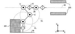
- FIGS. 4A to 4C are schematic diagrams (Nos. 1 to 3) showing an operation of linearly moving the control point 20 while maintaining the direction of the fourth axis R.
- FIG. FIGS. 5A to 5C are schematic diagrams (Nos. 1 to 3) showing the operation when the redundant axis E protrudes toward the third arm 16 side.
- the posture illustrated in FIG. 4A corresponds to the “second posture” described above
- the posture illustrated in FIG. 5A corresponds to the “first posture” described above.
- the obstacle 201 is, for example, a casing type device.
- the obstacle 202 is, for example, an upper wall and a lower wall, and schematically represents an apparatus such as a processing apparatus that needs to access an area in the back of a narrow passage.
- 4A to 4C show a shaft 40 obtained by extending the above-mentioned fourth axis R (see FIG. 2) and a control point 20 provided on the fourth axis R. That is, the fourth axis R and the axis 40 are coaxial, and the control point 20 moves on the axis 40.
- 4A to 4C for reference, the locus EL of the redundant axis E shown in FIG. 1 and the third axis U when the redundant axis E exists at the position shown in each of FIGS.
- a trajectory UL representing a movable position is shown.
- the posture determination unit 113 selects a posture that causes the redundant axis E to protrude to the side opposite to the obstacle 201 side (X-axis negative direction).
- the second axis L is rotated clockwise, and the redundant axis E is rotated so as to cooperate with the second axis L, whereby the control point 20 is moved along the axis 40 along the axis 40. It can be moved in the axial positive direction.
- FIG. 4B shows the posture of the robot 10 that has entered between the pair of obstacles 202. Further, in FIG. 4B, the positions of the redundant axis E and the third axis U shown in FIG. 4A are indicated by broken lines for reference.
- control point 20 By rotating the second axis L further clockwise from the posture shown in FIG. 4B and rotating the redundant axis E so as to cooperate with the rotation of the second axis L, the control point 20 is further moved along the axis 40 by X. It can be moved in the axial positive direction.
- FIG. 4C shows the posture of the robot 10 with the first arm 13 and the redundant arm 14 fully extended.
- the positions of the redundant axis E and the third axis U shown in FIG. 4B are indicated by broken lines for reference.
- FIGS. 5A to 5C are different from FIGS. 4A to 4C in the position of the obstacle 201.
- the posture determination unit 113 selects a posture that causes the redundant axis E to protrude to the side opposite to the obstacle 201 (X-axis positive direction). 5A, the second axis L is rotated clockwise and the redundant axis E is rotated so as to cooperate with the second axis L, whereby the control point 20 is moved along the axis 40 along the axis 40. It can be moved in the axial positive direction.
- FIG. 5B shows the posture of the robot 10 that has entered between the pair of obstacles 202. Further, in FIG. 5B, the positions of the redundant axis E and the third axis U shown in FIG. 5A are indicated by broken lines for reference.
- control point 20 is further moved along the axis 40. It can be moved in the positive direction of the X axis.
- FIG. 5C shows the posture of the robot 10 with the first arm 13 (see FIG. 1) and the redundant arm 14 (see FIG. 1) fully extended.
- the positions of the redundant axis E and the third axis U shown in FIG. 5B are indicated by broken lines for reference.
- FIGS. 5A to 5C show the case where the control point 20 is linearly moved in the positive direction of the X axis, but the control point 20 is moved in the negative direction of the X axis by operating in the reverse procedure. It is obvious that it can be moved linearly.
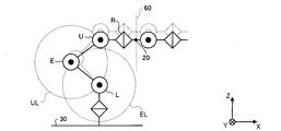
- FIGS. 6A to 6C are schematic diagrams (parts 1 to 3) showing an operation of moving the control point 20 in a direction perpendicular to the fourth axis R.
- FIG. 6A to 6C are schematic diagrams (parts 1 to 3) showing an operation of moving the control point 20 in a direction perpendicular to the fourth axis R.
- 6A to 6C show an axis 60 orthogonal to the above-described fourth axis R (see FIG. 2) at the position of the control point 20.
- 6A to 6C for reference, the locus EL of the redundant axis E shown in FIG. 1 and the third axis U when the redundant axis E exists at the position shown in each of FIGS.
- a trajectory UL representing a movable position is shown.
- 6A to 6C illustration of the obstacle 201 and the obstacle 202 shown in FIGS. 4A to 4C and the like is omitted.
- the control point 20 is moved along the axis 60 along the Z axis. It can be moved in the negative direction.
- FIG. 6B the positions of the joints shown in FIG. 6A are indicated by broken lines for reference.
- FIG. 6C The posture of the robot 10 is shown in FIG. 6C.
- the positions of the joints shown in FIG. 6B are indicated by broken lines for reference.
- the robot 10 can linearly move the control point 20 in a direction perpendicular to the fourth axis R while maintaining the direction of the fourth axis R.
- 6A to 6C show a case where the control point 20 is linearly moved in the negative direction of the Z axis, but the control point 20 is linearly moved in the positive direction of the Z axis by operating in the reverse procedure.
- the point that can be made is obvious.
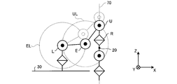
- FIGS. 7A to 7C are schematic diagrams (parts 1 to 3) showing an operation of moving the control point 20 along the fourth axis R in the vertical direction.
- 7A to 7C show a shaft 70 obtained by extending the fourth axis R (see FIG. 2) in the vertical direction, and a control point 20 provided on the fourth axis R. That is, the fourth axis R and the axis 70 are coaxial, and the control point 20 moves on the axis 70.
- 7A to 7C for reference, the locus EL of the redundant axis E shown in FIG. 1 and the third axis U when the redundant axis E exists at the position shown in each of FIGS.
- a trajectory UL representing a movable position is shown. 7A to 7C, illustration of the obstacle 201 and the obstacle 202 shown in FIGS. 4A to 4C and the like is omitted.
- the second axis L is rotated clockwise and the redundant axis E is rotated so as to cooperate with the second axis L, so that the control point 20 is negative along the axis 70 along the Z axis. It can be moved in the direction.
- FIG. 7B the positions of the redundant axis E and the third axis U shown in FIG. 7A are indicated by broken lines for reference.
- FIG. 7C The posture of the robot 10 is shown in FIG. 7C.
- the positions of the redundant axis E and the third axis U shown in FIG. 7B are indicated by broken lines for reference.
- the robot 10 can linearly move the control point 20 along the axis 70 coaxial with the fourth axis R while maintaining the direction of the fourth axis R in the vertical direction.
- FIGS. 7A to 7C show the case where the control point 20 is moved in the negative direction of the Z-axis, but it is also possible to move the control point 20 linearly in the positive direction of the Z-axis by operating in the reverse procedure. The point that can be done is obvious. Further, FIGS. 7A to 7C show the case where the tip side of the robot 10 is directed in the negative Z-axis direction, but the same operation is performed when the tip side of the robot 10 is directed in the positive Z-axis direction. It is also obvious that 20 can be moved linearly in the positive and negative directions of the Z axis.
- control point 20 can be linearly moved without changing the postures of the second arm 15 and the third arm 16 shown in FIG. 7A to 7C show a case where the control point 20 is linearly moved along the Z axis shown in the figure, but the control point 20 can also be linearly moved along the Y axis.
- the control point 20 When the control point 20 is moved linearly along the Y axis, the first axis S (see FIG. 1), the second axis L, and the redundant axis E are coordinated. In this case, since the third axis U turns around the first axis S, the direction of the third axis U changes. However, by cooperating the fourth axis R in a direction that cancels the change in the direction of the third axis U, the control point 20 is linearly moved in the positive and negative directions of the Y axis without changing the posture of the third arm 16. Can be made.
- FIG. 8 is a diagram for explaining singularity avoidance of the third arm 16.
- the fourth axis R, the fifth axis B, and the sixth axis T included in the third arm 16 the axis R0 obtained by extending the fourth axis R, and the control point 20 provided on the axis R0. It shows.
- FIG. 8 also shows an axis T0 obtained by extending the sixth axis T and an angle ⁇ 0 that is an angle formed by the axis T0 and the axis R0 described above.
- the arrow 80 indicates the direction in which the axis T0 is constrained.
- FIG. 8 illustrates the case where the axis R0 is horizontal and the axis T0 is obliquely downward, the axis T0 may be constrained to be horizontal or vertical. That is, FIG. 8 only shows that the axis T0 and the axis R0 form a predetermined angle.
- the avoidance operation unit 112 is configured even when the orientation of the sixth axis T of the third arm 16 is constrained by a relationship with a workpiece (not shown) or the like. It avoids that the 3rd arm 16 takes the attitude
- the singular point information 122 includes, for example, a condition that the fourth axis R and the sixth axis T are “inclination of ⁇ 0 degrees or less with respect to each other”. Such a condition is a condition indicating that the relationship between the fourth axis R and the sixth axis T is close to a singular point.
- the avoidance operation unit 112 Based on the condition of the singular point information 122, the avoidance operation unit 112 has an angle formed by the fourth axis R (axis R0 in FIG. 8) and the sixth axis T (axis T0 in FIG. 8) larger than ⁇ 0 degrees. Thus, the direction of the fourth axis R is adjusted.
- FIG. 9 is a flowchart showing a processing procedure executed by the robot control apparatus 100.
- the posture determination unit 113 reads the obstacle information 123 (step S101), and determines the bending directions of the first arm 13 and the redundant arm 14 (step S102).
- the operation control unit 111 acquires the rotation angle of each motor 10a (step S103) and calculates the posture of the robot 10 (step S104). Subsequently, the avoidance operation unit 112 determines whether or not the posture of the third arm 16 is close to a singular point (step S105).
- step S105 When the posture of the third arm 16 is close to a singular point (step S105, Yes), the avoidance operation unit 112 instructs the robot 10 to perform an avoidance operation using the redundant axis E via the operation control unit 111. (Step S106). If the posture of the third arm 16 is not close to the singular point (No in step S105), the process proceeds to step S107 without executing the process in step S106.
- the operation control unit 111 moves the control point 20 linearly while maintaining the direction of the fourth axis R (step S107), and ends the process.
Landscapes
- Engineering & Computer Science (AREA)
- Robotics (AREA)
- Mechanical Engineering (AREA)
- Manipulator (AREA)
Abstract
Priority Applications (5)
| Application Number | Priority Date | Filing Date | Title |
|---|---|---|---|
| JP2017525727A JP6477877B2 (ja) | 2015-06-30 | 2015-06-30 | ロボットシステム |
| DE112015006669.1T DE112015006669B4 (de) | 2015-06-30 | 2015-06-30 | Robotersystem |
| PCT/JP2015/068890 WO2017002208A1 (fr) | 2015-06-30 | 2015-06-30 | Système de robot |
| CN201580080840.6A CN107635730A (zh) | 2015-06-30 | 2015-06-30 | 机器人系统 |
| US15/807,574 US10836042B2 (en) | 2015-06-30 | 2017-11-09 | Robot system |
Applications Claiming Priority (1)
| Application Number | Priority Date | Filing Date | Title |
|---|---|---|---|
| PCT/JP2015/068890 WO2017002208A1 (fr) | 2015-06-30 | 2015-06-30 | Système de robot |
Related Child Applications (1)
| Application Number | Title | Priority Date | Filing Date |
|---|---|---|---|
| US15/807,574 Continuation US10836042B2 (en) | 2015-06-30 | 2017-11-09 | Robot system |
Publications (1)
| Publication Number | Publication Date |
|---|---|
| WO2017002208A1 true WO2017002208A1 (fr) | 2017-01-05 |
Family
ID=57608258
Family Applications (1)
| Application Number | Title | Priority Date | Filing Date |
|---|---|---|---|
| PCT/JP2015/068890 Ceased WO2017002208A1 (fr) | 2015-06-30 | 2015-06-30 | Système de robot |
Country Status (5)
| Country | Link |
|---|---|
| US (1) | US10836042B2 (fr) |
| JP (1) | JP6477877B2 (fr) |
| CN (1) | CN107635730A (fr) |
| DE (1) | DE112015006669B4 (fr) |
| WO (1) | WO2017002208A1 (fr) |
Cited By (5)
| Publication number | Priority date | Publication date | Assignee | Title |
|---|---|---|---|---|
| CN108687750A (zh) * | 2017-03-30 | 2018-10-23 | 发那科株式会社 | 机器人 |
| JP2022044794A (ja) * | 2017-03-28 | 2022-03-17 | 川崎重工業株式会社 | ロボット装置 |
| DE112021003148T5 (de) | 2020-08-21 | 2023-05-04 | Fanuc Corporation | Robotersteuervorrichtung |
| JP2023065973A (ja) * | 2021-10-28 | 2023-05-15 | 株式会社安川電機 | 塗装ロボットおよび塗装システム |
| JP2023090918A (ja) * | 2019-10-17 | 2023-06-29 | 株式会社Fuji | 多関節ロボット |
Families Citing this family (10)
| Publication number | Priority date | Publication date | Assignee | Title |
|---|---|---|---|---|
| JP6443875B2 (ja) * | 2014-10-24 | 2018-12-26 | ライフロボティクス株式会社 | ロボットアーム機構 |
| JP6915288B2 (ja) | 2017-02-08 | 2021-08-04 | オムロン株式会社 | 画像処理システム、画像処理装置、FPGA(Field Programmable Gate Array)における回路の再構成方法、および、FPGAにおける回路の再構成プログラム |
| JP2019177436A (ja) * | 2018-03-30 | 2019-10-17 | 日本電産株式会社 | ロボット制御装置、ロボットの関節の角度を求める方法、プログラム |
| JP6816070B2 (ja) * | 2018-08-24 | 2021-01-20 | ファナック株式会社 | 干渉回避装置およびロボットシステム |
| DE102019126465B4 (de) * | 2018-10-01 | 2021-02-11 | KBee AG | Verfahren und Vorrichtung zur Trajektorienbestimmung für serielle Manipulatoren |
| CN111571565A (zh) * | 2019-02-18 | 2020-08-25 | 沈阳新松机器人自动化股份有限公司 | 一种七轴工业机器人 |
| CN113423540B (zh) * | 2019-02-22 | 2025-01-28 | Abb瑞士股份有限公司 | 德尔塔机器人校准方法、控制系统、德尔塔机器人和机器人系统 |
| JP7737183B2 (ja) * | 2021-11-12 | 2025-09-10 | リブスメド インコーポレーテッド | 手術用ロボットアーム |
| JP7268774B1 (ja) * | 2022-03-31 | 2023-05-08 | 株式会社安川電機 | 塗装ロボットおよび塗装システム |
| JP2024045929A (ja) * | 2022-09-22 | 2024-04-03 | セイコーエプソン株式会社 | ロボットの教示方法および立体物印刷装置 |
Citations (7)
| Publication number | Priority date | Publication date | Assignee | Title |
|---|---|---|---|---|
| JPH05220681A (ja) * | 1992-02-06 | 1993-08-31 | Mitsubishi Electric Corp | ロボットおよびその制御方法 |
| JPH0647689A (ja) * | 1992-07-30 | 1994-02-22 | Kobe Steel Ltd | 多関節形ロボットの制御方法 |
| JPH07108476A (ja) * | 1993-10-12 | 1995-04-25 | Yamaha Motor Co Ltd | ロボットの直線方向作動装置 |
| JPH09314487A (ja) * | 1996-05-31 | 1997-12-09 | Mitsubishi Heavy Ind Ltd | 冗長軸を有するマニピュレータの制御方法 |
| JP2002210684A (ja) * | 2000-11-14 | 2002-07-30 | Daihen Corp | トランスファロボット |
| JP2007221031A (ja) * | 2006-02-20 | 2007-08-30 | Lintec Corp | 搬送装置及び搬送方法 |
| JP2012228761A (ja) * | 2011-04-27 | 2012-11-22 | Yaskawa Electric Corp | ロボットシステム及び被作業物の製造方法 |
Family Cites Families (14)
| Publication number | Priority date | Publication date | Assignee | Title |
|---|---|---|---|---|
| JPH0642090U (ja) * | 1992-11-20 | 1994-06-03 | 株式会社アマダ | 多関節ロボット |
| IT1272083B (it) * | 1993-12-17 | 1997-06-11 | Comau Spa | Robot industriale con gruppi riduttori integrati. |
| US6718647B2 (en) * | 2000-06-14 | 2004-04-13 | Renishaw Plc | Force sensing probe |
| JP5184602B2 (ja) * | 2001-10-22 | 2013-04-17 | 株式会社安川電機 | 多関節ロボット |
| JP2005517909A (ja) * | 2002-02-14 | 2005-06-16 | ファロ テクノロジーズ インコーポレーテッド | 多関節アームを有する可搬式座標測定器 |
| EP1633534B1 (fr) * | 2003-04-28 | 2018-09-12 | Nikon Metrology NV | Bras de machine de mesure de coordonnees a exosquelette |
| FR2861843B1 (fr) * | 2003-10-29 | 2006-07-07 | Romain Granger | Dispositif de connexion associe a un bras d'appareil de mesure tridimentionnelle a bras articules |
| WO2007075844A1 (fr) * | 2005-12-20 | 2007-07-05 | Intuitive Surgical, Inc. | Axe d'insertion telescopique d'un systeme de robot chirurgical |
| JP5415040B2 (ja) * | 2008-08-01 | 2014-02-12 | 三重電子株式会社 | 自動工具交換装置用モジュール |
| JP5464998B2 (ja) * | 2009-12-24 | 2014-04-09 | 株式会社Ihiエアロスペース | ロボットアームの干渉回避方法 |
| CN103769332B (zh) * | 2012-09-10 | 2017-12-01 | 发纳科机器人美国公司 | 冗余机器人及机器人喷漆系统 |
| JP5884785B2 (ja) * | 2013-07-30 | 2016-03-15 | 株式会社安川電機 | ロボット |
| EP3325233A1 (fr) * | 2015-07-23 | 2018-05-30 | SRI International Inc. | Bras robotique et système chirurgical robotique |
| US9827678B1 (en) * | 2016-05-16 | 2017-11-28 | X Development Llc | Kinematic design for robotic arm |
-
2015
- 2015-06-30 WO PCT/JP2015/068890 patent/WO2017002208A1/fr not_active Ceased
- 2015-06-30 CN CN201580080840.6A patent/CN107635730A/zh active Pending
- 2015-06-30 JP JP2017525727A patent/JP6477877B2/ja active Active
- 2015-06-30 DE DE112015006669.1T patent/DE112015006669B4/de active Active
-
2017
- 2017-11-09 US US15/807,574 patent/US10836042B2/en active Active
Patent Citations (7)
| Publication number | Priority date | Publication date | Assignee | Title |
|---|---|---|---|---|
| JPH05220681A (ja) * | 1992-02-06 | 1993-08-31 | Mitsubishi Electric Corp | ロボットおよびその制御方法 |
| JPH0647689A (ja) * | 1992-07-30 | 1994-02-22 | Kobe Steel Ltd | 多関節形ロボットの制御方法 |
| JPH07108476A (ja) * | 1993-10-12 | 1995-04-25 | Yamaha Motor Co Ltd | ロボットの直線方向作動装置 |
| JPH09314487A (ja) * | 1996-05-31 | 1997-12-09 | Mitsubishi Heavy Ind Ltd | 冗長軸を有するマニピュレータの制御方法 |
| JP2002210684A (ja) * | 2000-11-14 | 2002-07-30 | Daihen Corp | トランスファロボット |
| JP2007221031A (ja) * | 2006-02-20 | 2007-08-30 | Lintec Corp | 搬送装置及び搬送方法 |
| JP2012228761A (ja) * | 2011-04-27 | 2012-11-22 | Yaskawa Electric Corp | ロボットシステム及び被作業物の製造方法 |
Non-Patent Citations (2)
| Title |
|---|
| JING XIA ET AL.: "Analytical inverse kinematic computation for anthropomorphic manipulator based on human-like motion optimization and maximum reachable region optimization", PROCEEDINGS OF 2014 IEEE INTERNATIONAL CONFERENCE ON ROBOTICS AND BIOMIMETICS (ROBIO, December 2014 (2014-12-01), pages 2292 - 2297, XP032764947 * |
| MANJA KIRCANSKI: "Combined analytical-gradient- projection inverse kinematic solutions for simple redundant manipulators", PROCEEDINGS OF FIFTH INTERNATIONAL CONFERENCE ON ADVANCED ROBOTICS, 1991. 'ROBOTS IN UNSTRUCTURED ENVIRONMENTS', 91 ICAR., vol. 2, June 1991 (1991-06-01), pages 1228 - 1231, XP032159903 * |
Cited By (12)
| Publication number | Priority date | Publication date | Assignee | Title |
|---|---|---|---|---|
| JP2022044794A (ja) * | 2017-03-28 | 2022-03-17 | 川崎重工業株式会社 | ロボット装置 |
| JP7590998B2 (ja) | 2017-03-28 | 2024-11-27 | 川崎重工業株式会社 | ロボット装置 |
| CN108687750A (zh) * | 2017-03-30 | 2018-10-23 | 发那科株式会社 | 机器人 |
| JP2018167359A (ja) * | 2017-03-30 | 2018-11-01 | ファナック株式会社 | ロボット |
| CN108687750B (zh) * | 2017-03-30 | 2019-12-13 | 发那科株式会社 | 机器人 |
| US10618161B2 (en) | 2017-03-30 | 2020-04-14 | Fanuc Corporation | Robot |
| JP2023090918A (ja) * | 2019-10-17 | 2023-06-29 | 株式会社Fuji | 多関節ロボット |
| JP7576656B2 (ja) | 2019-10-17 | 2024-10-31 | 株式会社Fuji | 多関節ロボット |
| DE112021003148T5 (de) | 2020-08-21 | 2023-05-04 | Fanuc Corporation | Robotersteuervorrichtung |
| US12440976B2 (en) | 2020-08-21 | 2025-10-14 | Fanuc Corporation | Robot controller |
| JP2023065973A (ja) * | 2021-10-28 | 2023-05-15 | 株式会社安川電機 | 塗装ロボットおよび塗装システム |
| JP7364642B2 (ja) | 2021-10-28 | 2023-10-18 | 株式会社安川電機 | 塗装ロボットおよび塗装システム |
Also Published As
| Publication number | Publication date |
|---|---|
| JPWO2017002208A1 (ja) | 2018-03-08 |
| JP6477877B2 (ja) | 2019-03-06 |
| DE112015006669B4 (de) | 2019-11-28 |
| US20180065254A1 (en) | 2018-03-08 |
| US10836042B2 (en) | 2020-11-17 |
| CN107635730A (zh) | 2018-01-26 |
| DE112015006669T5 (de) | 2018-03-29 |
Similar Documents
| Publication | Publication Date | Title |
|---|---|---|
| JP6477877B2 (ja) | ロボットシステム | |
| JP6279862B2 (ja) | 冗長ロボットを制御する方法 | |
| JP5895628B2 (ja) | ロボットの制御方法及びロボット制御装置、並びにロボット制御システム | |
| JP5701055B2 (ja) | 7軸多関節ロボットの制御方法、制御プログラム及びロボット制御装置 | |
| JP6746990B2 (ja) | ロボット制御装置及びロボットシステム | |
| JP2016516487A5 (fr) | ||
| CN109514599B (zh) | 机器人系统和工件的制造方法 | |
| JP7144754B2 (ja) | 多関節ロボットおよび多関節ロボットシステム | |
| WO2012090440A1 (fr) | Dispositif de commande et procédé d'apprentissage pour robot à articulations multiples à sept arbres | |
| JP2007118177A (ja) | 双腕ロボット | |
| WO2019163997A1 (fr) | Dispositif de travail utilisant un mécanisme de liaison parallèle et procédé de commande de celui-ci | |
| WO2020161910A1 (fr) | Dispositif de commande, procédé de commande et support d'enregistrement | |
| WO2014192884A1 (fr) | Solution cinématique inverse destinée à un mécanisme de liaison à articulations multiples, et dispositif pour la création de données didactiques à l'aide d'une solution cinématique inverse | |
| US12440976B2 (en) | Robot controller | |
| JP2013215839A (ja) | 冗長自由度を持つロボットの制御方法及びロボット制御装置、並びにロボット制御システム | |
| JP6252273B2 (ja) | ロボットの制御方法、ロボットの制御装置 | |
| JPH11198071A (ja) | 冗長ロボットの冗長軸位置決定方法 | |
| JP6281351B2 (ja) | ロボットの制御方法、ロボットの制御装置 | |
| CN114055442A (zh) | 机器人以及机器人系统 | |
| JP7352267B1 (ja) | 多関節ロボット、多関節ロボットの制御方法、ロボットシステム、及び、物品の製造方法 | |
| JP6252278B2 (ja) | ロボットの制御方法、ロボットの制御装置 | |
| JPH025558B2 (fr) | ||
| JP2014124733A (ja) | ロボット制御装置及びロボットの制御方法 | |
| JP2005199412A (ja) | 制御方法および制御装置 |
Legal Events
| Date | Code | Title | Description |
|---|---|---|---|
| 121 | Ep: the epo has been informed by wipo that ep was designated in this application |
Ref document number: 15897135 Country of ref document: EP Kind code of ref document: A1 |
|
| ENP | Entry into the national phase |
Ref document number: 2017525727 Country of ref document: JP Kind code of ref document: A |
|
| WWE | Wipo information: entry into national phase |
Ref document number: 112015006669 Country of ref document: DE |
|
| 122 | Ep: pct application non-entry in european phase |
Ref document number: 15897135 Country of ref document: EP Kind code of ref document: A1 |