WO2017002214A1 - Système à cycle de réfrigération - Google Patents
Système à cycle de réfrigération Download PDFInfo
- Publication number
- WO2017002214A1 WO2017002214A1 PCT/JP2015/068900 JP2015068900W WO2017002214A1 WO 2017002214 A1 WO2017002214 A1 WO 2017002214A1 JP 2015068900 W JP2015068900 W JP 2015068900W WO 2017002214 A1 WO2017002214 A1 WO 2017002214A1
- Authority
- WO
- WIPO (PCT)
- Prior art keywords
- refrigerant
- refrigeration cycle
- indoor unit
- unit
- indoor
- Prior art date
- Legal status (The legal status is an assumption and is not a legal conclusion. Google has not performed a legal analysis and makes no representation as to the accuracy of the status listed.)
- Ceased
Links
Images




Classifications
-
- F—MECHANICAL ENGINEERING; LIGHTING; HEATING; WEAPONS; BLASTING
- F24—HEATING; RANGES; VENTILATING
- F24F—AIR-CONDITIONING; AIR-HUMIDIFICATION; VENTILATION; USE OF AIR CURRENTS FOR SCREENING
- F24F11/00—Control or safety arrangements
- F24F11/30—Control or safety arrangements for purposes related to the operation of the system, e.g. for safety or monitoring
- F24F11/32—Responding to malfunctions or emergencies
- F24F11/36—Responding to malfunctions or emergencies to leakage of heat-exchange fluid
-
- F—MECHANICAL ENGINEERING; LIGHTING; HEATING; WEAPONS; BLASTING
- F24—HEATING; RANGES; VENTILATING
- F24F—AIR-CONDITIONING; AIR-HUMIDIFICATION; VENTILATION; USE OF AIR CURRENTS FOR SCREENING
- F24F11/00—Control or safety arrangements
- F24F11/70—Control systems characterised by their outputs; Constructional details thereof
- F24F11/72—Control systems characterised by their outputs; Constructional details thereof for controlling the supply of treated air, e.g. its pressure
- F24F11/74—Control systems characterised by their outputs; Constructional details thereof for controlling the supply of treated air, e.g. its pressure for controlling air flow rate or air velocity
- F24F11/745—Control systems characterised by their outputs; Constructional details thereof for controlling the supply of treated air, e.g. its pressure for controlling air flow rate or air velocity the air flow rate increasing with an increase of air-current or wind pressure
-
- F—MECHANICAL ENGINEERING; LIGHTING; HEATING; WEAPONS; BLASTING
- F24—HEATING; RANGES; VENTILATING
- F24F—AIR-CONDITIONING; AIR-HUMIDIFICATION; VENTILATION; USE OF AIR CURRENTS FOR SCREENING
- F24F11/00—Control or safety arrangements
- F24F11/70—Control systems characterised by their outputs; Constructional details thereof
- F24F11/72—Control systems characterised by their outputs; Constructional details thereof for controlling the supply of treated air, e.g. its pressure
- F24F11/79—Control systems characterised by their outputs; Constructional details thereof for controlling the supply of treated air, e.g. its pressure for controlling the direction of the supplied air
-
- F—MECHANICAL ENGINEERING; LIGHTING; HEATING; WEAPONS; BLASTING
- F24—HEATING; RANGES; VENTILATING
- F24F—AIR-CONDITIONING; AIR-HUMIDIFICATION; VENTILATION; USE OF AIR CURRENTS FOR SCREENING
- F24F11/00—Control or safety arrangements
- F24F11/70—Control systems characterised by their outputs; Constructional details thereof
- F24F11/80—Control systems characterised by their outputs; Constructional details thereof for controlling the temperature of the supplied air
- F24F11/83—Control systems characterised by their outputs; Constructional details thereof for controlling the temperature of the supplied air by controlling the supply of heat-exchange fluids to heat-exchangers
- F24F11/84—Control systems characterised by their outputs; Constructional details thereof for controlling the temperature of the supplied air by controlling the supply of heat-exchange fluids to heat-exchangers using valves
-
- F—MECHANICAL ENGINEERING; LIGHTING; HEATING; WEAPONS; BLASTING
- F25—REFRIGERATION OR COOLING; COMBINED HEATING AND REFRIGERATION SYSTEMS; HEAT PUMP SYSTEMS; MANUFACTURE OR STORAGE OF ICE; LIQUEFACTION SOLIDIFICATION OF GASES
- F25B—REFRIGERATION MACHINES, PLANTS OR SYSTEMS; COMBINED HEATING AND REFRIGERATION SYSTEMS; HEAT PUMP SYSTEMS
- F25B2500/00—Problems to be solved
- F25B2500/22—Preventing, detecting or repairing leaks of refrigeration fluids
- F25B2500/222—Detecting refrigerant leaks
Definitions
- the present invention relates to a refrigeration cycle system including a plurality of indoor units and a plurality of refrigerant leak detection devices.
- an air conditioner including a refrigerant leakage sensor is known (for example, see Patent Document 1).
- the compressor and the fan motor are stopped, and the refrigerant circuit is shut off by the electromagnetic shut-off valve, thereby suppressing the refrigerant leak. ing.
- the concentration of the leaked refrigerant may locally increase in the vicinity of the refrigerant leak location.
- the present invention has been made against the background of the above problems, and an object of the present invention is to obtain a refrigeration cycle system that suppresses locally increasing the concentration of the leaked refrigerant when the refrigerant leaks. Yes.
- a refrigeration cycle system includes a plurality of indoor units that are installed indoors and constitute a part of a refrigeration cycle apparatus that circulates refrigerant, and a plurality of refrigerants that are installed indoors and detect refrigerant leakage. And a control device that controls the refrigeration cycle device by obtaining detection results of the leakage detection device and the plurality of refrigerant leakage detection devices, and the control device detects the leakage of the refrigerant. Furthermore, the air flow rate of the indoor unit closest to the refrigerant leakage detection device that has detected refrigerant leakage is increased.
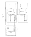
- FIG. [Refrigeration cycle system] 1 is a diagram illustrating an example of the configuration of a refrigeration cycle system according to Embodiment 1 of the present invention.
- a refrigeration cycle system 100 illustrated in FIG. 1 is applied to, for example, a unit cooler that cools a room inside a warehouse 50, and controls a plurality of refrigeration cycle apparatuses 1 and a plurality of refrigeration cycle apparatuses 1.
- the control apparatus 30 to perform is provided.
- the refrigeration cycle system 100 can also be applied to an air conditioning system that performs indoor air conditioning inside a room.
- the solid line connecting the heat source unit 2 and the indoor unit 4 schematically describes the refrigerant piping.
- the broken line connecting the lines schematically describes the communication line.
- the refrigeration cycle apparatus 1 circulates a refrigerant, and the heat source unit 2 and the indoor unit 4 are connected by a refrigerant pipe.
- the heat source unit 2 and the indoor unit 4 are connected by a communication line, and a control unit (not shown) of the heat source unit 2 and a control unit (not shown) of the indoor unit 4 communicate with each other while performing refrigeration. Control of the cycle apparatus 1 is performed.
- coolant applied to the refrigerating-cycle apparatus 1 contains R32 or R1234yf, for example, another kind of refrigerant
- first refrigeration cycle apparatus 1-1 includes a first refrigeration cycle apparatus 1-1, a second refrigeration cycle apparatus 1-2, a third refrigeration cycle apparatus 1-3, and a fourth refrigeration cycle apparatus 1-4. Although four refrigeration cycle apparatuses 1 are included, the refrigeration cycle system 100 only needs to include one or more refrigeration cycle apparatuses 1.
- the first refrigeration cycle apparatus 1-1 includes a first heat source unit 2-1, a first indoor unit 4-1A and a second indoor unit 4-1B connected in parallel to the first heat source unit 2-1.
- the second refrigeration cycle apparatus 1-2 includes a second heat source unit 2-2, a third indoor unit 4-2A and a fourth indoor unit 4-2B connected in parallel to the second heat source unit 2-2.
- the third refrigeration cycle apparatus 1-3 includes a third heat source unit 2-3 and a fifth indoor unit 4-3 connected to the third heat source unit 2-3.
- the fourth refrigeration cycle apparatus 1-4 includes a fourth heat source unit 2-4 and a sixth indoor unit 4-4 connected to the fourth heat source unit 2-4. Note that each of the plurality of refrigeration cycle apparatuses 1 only needs to include one or more indoor units 4, and may include, for example, three or more indoor units 4.
- Each of the indoor units 4 accommodates therein a refrigerant leakage detection device 8 that detects refrigerant leakage. That is, the first indoor unit 4-1A includes a first refrigerant leak detection device 8-1A, and the second indoor unit 4-1B includes a second refrigerant leak detection device 8-1B.
- the indoor unit 4-2A includes a third refrigerant leak detection device 8-2A, and the fourth indoor unit 4-2B includes a fourth refrigerant leak detection device 8-2B.
- 3 includes a fifth refrigerant leak detection device 8-3, and the sixth indoor unit 4-4 includes a sixth refrigerant leak detection device 8-4.
- the refrigerant leakage detection device 8 may be installed in the vicinity of each indoor unit 4.
- the refrigerant leak detection device 8 is housed in the interior of the indoor unit 4 or installed in the vicinity of the indoor unit 4 so that when refrigerant leaks in the room inside the warehouse 50, the refrigerant leak is detected at an early stage. can do.
- the refrigerant leak detection device 8 is installed close to the indoor unit 4, for example, the refrigerant leak detection device 8 is configured separately from the indoor unit 4, and communicates with the indoor unit 4 or the control device 30. Connected with.
- the refrigerant leak detection device 8 may be disposed close to a flare connection part of the refrigerant pipe, for example, where the refrigerant may leak.
- FIG. 2 is a diagram illustrating an example of the configuration of the refrigeration cycle apparatus illustrated in FIG.
- first refrigeration cycle apparatus 1-1 will be described with reference to FIG. 2, and the second refrigeration cycle apparatus 1-2, the third refrigeration cycle apparatus 1-2 will be described. Since the refrigeration cycle apparatus 1-3 and the fourth refrigeration cycle apparatus 1-4 have the same configuration as the first refrigeration cycle apparatus 1-1, description thereof is omitted.
- the first refrigeration cycle apparatus 1-1 will be described as the refrigeration cycle apparatus 1
- the first heat source unit 2-1 will be described as the heat source unit 2
- the first compressor 20-1 will be described as the compressor 20.
- the first heat source side heat exchanger 22-1 will be described as the heat source side heat exchanger 22, and the first indoor unit 4-1A and the second indoor unit 4-1B will be described as the indoor unit 4.
- First fan 5-1A and second fan 5-1B will be described as fan 5
- first wind direction control unit 6-1A and second wind direction control unit 6-1B will be described as wind direction control unit 6
- the first refrigerant leakage detection device 8-1A and the second refrigerant leakage detection device 8-1B will be described as the refrigerant leakage detection device 8
- the first usage side heat exchanger 40-1A and the second usage side heat exchanger 40-1B will be described. Is described as the use side heat exchanger 40,
- the expander 42-1A and second expander 42-1B perform described as expander 42, in some cases a description of the first switching device 44-1A and second switchgear 44-1B as an opening and closing device 44.
- the compressor 20 is installed, for example, outdoors outside the warehouse 50, and includes a compressor 20 and a heat source side heat exchanger 22.
- the compressor 20 sucks and compresses the refrigerant and discharges it in a high-temperature and high-pressure state.
- the compressor 20 is an inverter compressor capable of capacity control, for example, but may be of a constant speed type.
- the heat source side heat exchanger 22 exchanges heat between the refrigerant and air, for example.
- a blower fan (not shown) that blows air to the heat source side heat exchanger 22 is installed in the vicinity of the heat source side heat exchanger 22.
- the indoor unit 4 is installed in a room inside the warehouse 50, and includes a use side heat exchanger 40, an expansion device 42, and an opening / closing device 44.
- the expansion device 42 expands the refrigerant, and is, for example, a LEV (linear electronic expansion valve) whose opening degree can be adjusted, but may be a capillary tube or the like whose opening degree cannot be adjusted.
- the opening / closing device 44 controls the inflow of the refrigerant to the use side heat exchanger 40, and is constituted by, for example, an opening / closing valve.
- the use side heat exchanger 40 exchanges heat between the refrigerant and air.
- a fan 5 that blows air to the use side heat exchanger 40 is installed in the vicinity of the use side heat exchanger 40.
- the fan 5 can adjust the air volume of blowing by controlling the rotation speed. By operating the fan 5, the air inside the warehouse 50 around the indoor unit 4 is taken into the indoor unit 4. The air taken into the indoor unit 4 is heat-exchanged by the use side heat exchanger 40 and blown out into the warehouse 50 outside the indoor unit 4.
- the indoor unit 4 also has a wind direction control unit 6 that controls the direction of air blown from the indoor unit 4.
- the wind direction control part 6 is comprised including the louver formed with the some plate-shaped member, for example.
- the refrigerant compressed by the compressor 20 of the heat source device 2 flows through the heat source side heat exchanger 22 and is condensed.
- the refrigerant condensed in the heat source side heat exchanger 22 flows out of the heat source unit 2 and flows into the indoor unit 4.
- the refrigerant flowing out from the heat source unit 2 is branched into a refrigerant flowing through the first indoor unit 4-1A and a refrigerant flowing through the second indoor unit 4-1B.
- the refrigerant flowing into the first indoor unit 4-1A passes through the first opening / closing device 44-1A and is expanded by the first expansion device 42-1A.
- the refrigerant expanded by the first expansion device 42-1A flows through the first usage side heat exchanger 40-1A and is evaporated.
- the refrigerant evaporated in the first usage-side heat exchanger 40-1A flows out from the first indoor unit 4-1A and merges with the refrigerant flowing out from the second indoor unit 4-1B.
- the refrigerant flowing into the second indoor unit 4-1B passes through the second opening / closing device 44-1B and is expanded by the second expansion device 42-1B.
- the refrigerant expanded by the second expansion device 42-1B flows through the second usage side heat exchanger 40-1B and is evaporated.
- the refrigerant evaporated in the second usage side heat exchanger 40-1B flows out from the second indoor unit 4-1B and merges with the refrigerant flowing out from the first indoor unit 4-1A.
- the refrigerant in which the refrigerant flowing out from the first indoor unit 4-1A and the refrigerant flowing out from the second indoor unit 4-1B merged flows into the heat source unit 2, is sucked into the compressor 20, and is compressed again.
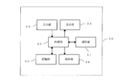
- FIG. 3 is a diagram illustrating an example of the configuration of the control device illustrated in FIG. 1.
- the control device 30 performs overall control of the refrigeration cycle system 100, and includes, for example, an analog circuit, a digital circuit, a CPU, or a combination of two or more thereof.
- the control device 30 can acquire detection results from, for example, the refrigerant leakage detection device 8, a pressure sensor (not shown), a temperature sensor (not shown), and the like, and can control each of the refrigeration cycle devices 1. .
- the control device 30 includes a communication unit 31, a processing unit 32, a display unit 33, an input unit 34, a storage unit 35, and a notification unit 36.
- the communication unit 31 is for communicating with each of the plurality of refrigeration cycle apparatuses 1.
- the control device 30 and each of the plurality of refrigeration cycle devices 1 can perform wired or wireless communication via the communication unit 31.
- the processing unit 32 performs a preset process using, for example, information input from the input unit 34, information acquired from the storage unit 35, information acquired from each of the plurality of refrigeration cycle apparatuses 1, and the like. It is.
- the display unit 33 displays the state of the refrigeration cycle system 100 and the like, and includes a liquid crystal screen, for example.
- the input unit 34 is used to input an instruction to the refrigeration cycle system 100 by a user or the like, and includes a switch, for example.
- the user or the like can use the input unit 34 to instruct the plurality of refrigeration cycle apparatuses 1 regarding the indoor target temperature.
- the display unit 33 and the input unit 34 may be a touch panel or the like in which these are integrally formed.
- the storage unit 35 includes, for example, a non-volatile memory, and stores a control program for controlling the refrigeration cycle system 100 and the like.
- the storage unit 35 stores position coordinates related to the positions of the plurality of indoor units 4, position coordinates related to the positions of the plurality of refrigerant leak detection devices 8, and the like.
- the input unit 34 is used to set the position coordinates relating to the respective positions of the plurality of indoor units 4, and the plurality of refrigerant leaks.
- the position coordinate regarding each position of the detection apparatus 8 is input.
- the notification unit 36 performs notification, and includes, for example, a lamp that performs notification using light, a buzzer that performs notification using sound, and the like. In the case where the control device 30 performs notification using the display unit 33, the notification unit 36 may be omitted.
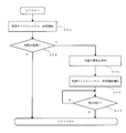
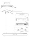
- FIG. 4 is a diagram for explaining an example of the operation of the refrigeration cycle system shown in FIG.
- the refrigeration cycle system 100 is performing normal operation.
- the process returns to step S02 and the normal operation is continued.
- step S04 When the leakage of the refrigerant is detected in step S04, the process proceeds to step S06 to notify that the refrigerant is leaking.
- the notification unit 36 illustrated in FIG. 3 performs notification by sound or light, and the display unit 33 displays the leakage point of the refrigerant.
- the control device 30 estimates the refrigerant leak location using the position coordinates of the refrigerant leak detection device 8 that has detected the refrigerant leak, and causes the display unit 33 to display the estimated refrigerant leak location.
- the installation position of the indoor unit 4 including the refrigerant leak detection device 8 that detects the refrigerant leak is displayed on the display unit 33. Is done.
- the user who has received the notification can easily identify the location where the refrigerant is leaking and perform maintenance or the like. Note that the refrigerant leakage notification started in step S06 is continued until the notification is canceled in the following step S10.
- the refrigerant stirring operation of the refrigeration cycle system 100 is executed in step S08.
- the second refrigerant leak detection device 8-1B disposed closest to the second indoor unit 4-1B Detect leaks.
- the control device 30 acquires a detection result indicating that the refrigerant is leaking from the second refrigerant leak detection device 8-1B, and detects the second refrigerant leak detection device 8-1B closest to the second refrigerant leak detection device 8-1B that has detected the refrigerant leak. Increase the air volume of the indoor unit 4-1B.
- the second indoor unit 4-1B can increase the amount of air blown by increasing the rotational speed of the second fan 5-1B shown in FIG.
- the air flow rate of the second indoor unit 4-1B By increasing the air flow rate of the second indoor unit 4-1B, the air around the second indoor unit 4-1B where the refrigerant is leaking is agitated, so the concentration of the leaked refrigerant is locally increased. It is suppressed.
- the control device 30 closes the second opening / closing device 44-1B of the second indoor unit 4-1B closest to the second refrigerant leakage detection device 8-1B that has detected the refrigerant leakage. Set it to the state.
- the second opening / closing device 44-1B By closing the second opening / closing device 44-1B, the inflow of refrigerant to the second indoor unit 4-1B is stopped, so that leakage of refrigerant from the second indoor unit 4-1B is suppressed. As a result, it is suppressed that the concentration of the leaked refrigerant locally increases.
- the control device 30 includes the first refrigeration cycle apparatus 1 to which the second indoor unit 4-1B closest to the second refrigerant leakage detection apparatus 8-1B that has detected refrigerant leakage is connected. It is also possible to set the open / close devices 44 of all the indoor units 4 of ⁇ 1 to the closed state. By closing the first opening / closing device 44-1A and the second opening / closing device 44-1B shown in FIG. 2, the pressure on the low pressure side of the first compressor 20-1 of the first refrigeration cycle apparatus 1-1 is changed. Decreases, the low pressure cut of the first compressor 20-1 works, and the first compressor 20-1 stops.
- the low pressure cut value at which the low pressure cut of the compressor 20 is performed may be a value equal to or higher than the atmospheric pressure and close to the atmospheric pressure.
- the control device 30 includes at least one of the indoor units 4 other than the second indoor unit 4-1B closest to the second refrigerant leak detection device 8-1B that has detected the refrigerant leak.
- the direction of the air blown from one indoor unit 4 may be directed to the second indoor unit 4-1B. Since the indoor unit 4 other than the second refrigerant leak detection device 8-1B where the refrigerant is leaking blows air toward the second indoor unit 4-1B, the leaked refrigerant is further agitated. It is further suppressed that the concentration of the refrigerant is locally increased.
- the indoor units 4 other than the second indoor unit 4-1B that blow air toward the second indoor unit 4-1B in which the refrigerant has leaked are the first refrigeration units to which the second indoor unit 4-1B is connected.
- the indoor unit 4 connected to the refrigeration cycle apparatus 1 other than the cycle apparatus 1-1 may be selected.
- the control device 30 includes the first refrigeration cycle apparatus 1 to which the second indoor unit 4-1B closest to the second refrigerant leakage detection apparatus 8-1B that has detected refrigerant leakage is connected. It is preferable to increase the load of the refrigeration cycle apparatus 1 other than -1. By increasing the load of the refrigeration cycle apparatus 1 other than the first refrigeration cycle apparatus 1-1 in which the refrigerant is leaking, the temperature inside the warehouse 50 is suppressed from fluctuating.
- the load of the refrigeration cycle apparatus 1 can be increased by increasing the rotational speed of the compressor 20, for example.
- step S10 the process returns to step S02, and the normal operation of the refrigeration cycle system 100 is resumed.
- the release of the refrigerant leakage notification is performed by, for example, an input from the notification unit 36 or the display unit 33 to the input unit 34 of the control device 30 or a reset switch or the like that is not illustrated. It is executed by doing.
- the refrigerant agitation operation continues to be executed, and therefore the locally increased concentration of the leaked refrigerant is suppressed.
- the refrigerant leakage notification is canceled, the fact that the refrigerant has leaked continues to be notified, so that the user can be surely recognized that an abnormality has occurred in the refrigeration cycle system 100.
- the refrigeration cycle system 100 is installed indoors and includes a plurality of indoor units 4 that constitute a part of the refrigeration cycle apparatus 1 that circulates the refrigerant, and is installed indoors.
- coolant leakage detection apparatus 8 which detects the leakage of this, and the control apparatus 30 which acquires the detection result of the several refrigerant
- the control device 30 increases the air flow rate of the indoor unit 4 closest to the refrigerant leak detection device 8 that has detected the refrigerant leak when the refrigerant leak detection device 8 detects the refrigerant leak.
- the refrigeration cycle system 100 of this embodiment even if the refrigerant leaks inside the warehouse 50, since the leaked refrigerant is diffused, the concentration of the leaked refrigerant is the warehouse. The local increase in the interior of the 50 can be suppressed.
- the control apparatus 30 is the direction of ventilation of at least one indoor unit 4 among the indoor units 4 other than the indoor unit 4 closest to the refrigerant leakage detection device 8 that has detected the refrigerant leakage. Is directed to the indoor unit 4 that is closest to the refrigerant leakage detection device 8 that has detected the refrigerant leakage, so that the leaked refrigerant can be further agitated. Therefore, according to this embodiment, it is possible to further suppress the concentration of the leaked refrigerant from locally increasing inside the warehouse 50. Note that the indoor unit 4 that blows air toward the indoor unit 4 that is closest to the refrigerant leak detection device 8 that has detected the refrigerant leak may increase the air volume and blow air.
- each of the plurality of indoor units 4 includes an opening / closing device 44 that controls the inflow of refrigerant into the indoor unit 4. Since the control device 30 closes the opening / closing device 44 of the indoor unit 4 closest to the refrigerant leakage detection device 8 that has detected the refrigerant leakage, the control device 30 enters the room from the refrigeration cycle apparatus 1 where the refrigerant is leaking. The risk of leakage of the refrigerant is suppressed. Further, the control device 30 closes the open / close devices 44 of all the indoor units 4 of the refrigeration cycle apparatus 1 to which the indoor unit 4 closest to the refrigerant leak detection device 8 that has detected the refrigerant leak is connected. Good.
- the refrigeration cycle system 100 of the example of this embodiment includes a plurality of refrigeration cycle apparatuses 1.
- the refrigeration cycle apparatus 1 in which the refrigerant leaks stops the circulation of the refrigerant, and the refrigeration cycle apparatus 1 in which the refrigerant does not leak operates by circulating the refrigerant so that the temperature in the room inside the warehouse 50 is increased. Fluctuation can be suppressed.
- the control device 30 includes at least one refrigeration cycle device 1 among the refrigeration cycle devices 1 other than the refrigeration cycle device 1 to which the indoor unit 4 closest to the refrigerant leakage detection device 8 that has detected refrigerant leakage is connected. It is good to increase the load.
- the temperature in the room inside the warehouse 50 varies by increasing the load of the refrigeration cycle apparatus 1 in which the refrigerant is not leaking. This can be further suppressed.
- the temperature inside the warehouse 50 is locally increased. Can be suppressed.
- the refrigerant applied to the refrigeration cycle apparatus 1 of the refrigeration cycle system 100 of this embodiment includes a refrigerant having a slight combustibility such as R32 or R1234yf
- the above-described effect becomes particularly remarkable. That is, since the refrigerant having a slight combustibility such as R32 or R1234yf may burn when the refrigerant concentration in the air is between the combustion lower limit concentration LFL and the combustion upper limit concentration UFL, Even if the refrigerant leaks into the room, the refrigerant will not burn if the refrigerant concentration can be kept lower than the lower combustion limit concentration LFL in the room.
- the leaked refrigerant when the leakage of the refrigerant is detected, the leaked refrigerant is diffused, so that the refrigerant concentration is suppressed to be equal to or higher than the lower combustion limit concentration LFL. Therefore, according to this embodiment, even if the refrigerant having slight combustibility leaks in the room, the risk of the leaked refrigerant burning is suppressed.
- This embodiment is not limited to the above description.
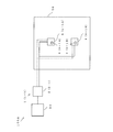
- FIG. 5 is a diagram illustrating the configuration of Modification 1 of the refrigeration cycle system according to Embodiment 1 of the present invention.
- a refrigeration cycle system 100A of Modification 1 shown in FIG. 5 includes a first heat source unit 2-1 and two indoor units 4 connected in parallel to the first heat source unit 2-1. This includes one first refrigeration cycle device 1-1 having an indoor unit 4-1A and a second indoor unit 4-1B. Also in the refrigeration cycle system 100 ⁇ / b> A of the first modification, when the refrigerant leaks, the refrigerant is diffused, and the concentration of the leaked refrigerant can be suppressed from becoming locally high in the interior of the warehouse 50.
- FIG. 6 is a diagram for explaining the configuration of Modification 2 of the refrigeration cycle system according to Embodiment 1 of the present invention.
- a refrigeration cycle system 100B of Modification 2 shown in FIG. 6 includes a first refrigeration cycle apparatus 1-1 and a second refrigeration cycle apparatus 1-2, which are two refrigeration cycle apparatuses 1.
- the first refrigeration cycle apparatus 1-1 includes a first heat source unit 2-1, and a first indoor unit 4-1A connected to the first heat source unit 2-1
- the second refrigeration cycle apparatus 1 -2 has a second heat source unit 2-2 and a third indoor unit 4-2A connected to the second heat source unit 2-2.
- the refrigeration cycle apparatus 1 in which the refrigerant leaks stops the circulation of the refrigerant, and the refrigeration cycle apparatus 1 in which the refrigerant does not leak operates by circulating the refrigerant. By this, it can suppress that the temperature of the room
- the refrigerant leakage detection device 8 is stored in the indoor unit 4 or installed in the vicinity of the indoor unit 4.
- a leak detection device 8 may be provided.
- the further refrigerant leakage detection device 8 may be disposed on a wall or a pillar of the warehouse 50 below the indoor unit 4 inside the warehouse 50. Because the refrigerant has a higher density than air, the refrigerant leaking into the air is likely to accumulate downward. For example, when the refrigerant concentration increases in the lower part of the room, the indoor unit 4 blows air downward, whereby the leaked refrigerant is stirred and the concentration of the leaked refrigerant is locally increased. It is suppressed.
- control device 30 causes the indoor unit 4 to blow air toward the refrigerant leakage detection device 8 that has detected a refrigerant having a high concentration, thereby suppressing the refrigerant concentration from increasing locally in the room. Can do.
- the further refrigerant leak detection devices 8 are preferably arranged at equal intervals in the room. By installing the refrigerant leak detection devices 8 at equal intervals in the room, the concentration of the refrigerant locally increases indoors. The fear is suppressed.
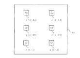
- FIG. 7 is a diagram for explaining an example of the direction of air flow of a plurality of indoor units when refrigerant leaks indoors in the refrigeration cycle system shown in FIG.
- the refrigerant leaks from the second indoor unit 4-1B, and the other indoor units 4 other than the second indoor unit 4-1B send air toward the second indoor unit 4-1B. Is going.
- the direction of the air blow of the second indoor unit 4-1B is a direction that does not oppose the direction of the air blow of other indoor units 4 other than the second indoor unit 4-1B.
- all the indoor units 4 other than the indoor unit 4 in which the refrigerant leaks blows air toward the indoor unit 4 in which the refrigerant leaks, thereby quickly stirring the leaked refrigerant. Can be made.
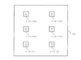
- FIG. 8 is a diagram for explaining another example of the direction of air flow of a plurality of indoor units when the refrigerant leaks indoors in the refrigeration cycle system shown in FIG.
- the refrigerating cycle system shown in Drawing 1 it is a figure explaining other examples of the direction of ventilation of a plurality of indoor units when a refrigerant leaks indoors.
- FIG. 8 when the refrigerant leaks indoors, all indoor units 4 blow air so that the refrigerant circulates in the room in an annular shape, thereby suppressing the refrigerant concentration from increasing locally. can do.
- FIG. 9 when the direction of air blowing of the indoor unit 4 cannot be freely adjusted, as shown in FIG. 9, the air blowing of each of the plurality of indoor units 4 is performed so that the directions of air blowing do not face each other. You can adjust the direction.
- FIG. 10 is a diagram illustrating another example of the direction of air blown by a plurality of indoor units when refrigerant leaks indoors in the refrigeration cycle system shown in FIG.
- the warehouse 50 includes a ventilator 52 that ventilates the outside of the warehouse 50
- the indoor unit 4 blows air toward the ventilator 52 when the refrigerant leaks indoors.
- the refrigerant leaking into the warehouse 50 is discharged to the outside of the warehouse 50.
- the air blower which is abbreviate
- omitting illustration is a circulator by which the control apparatus 30 controls a wind direction and an air volume, for example.
- FIG. FIG. 11 is a diagram for explaining an example of the operation of the refrigeration cycle system according to Embodiment 2 of the present invention
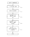
- FIG. 12 is a diagram for explaining an example of the refrigeration cycle apparatus specifying operation shown in FIG.
- the same operation as the operation of FIG. 4 is denoted by the same reference numeral, and the description thereof is omitted or simplified.
- the refrigeration cycle apparatus specifying operation is executed in step S20.
- the refrigeration cycle apparatus 1 in which the refrigerant is leaking is specified. This is because the refrigerant leaks from the refrigerant pipe connecting the heat source unit 2 and the indoor unit 4 or is estimated from the position of the refrigerant leak detection device 8 that detects the refrigerant leak depending on the wind direction of the indoor unit 4 or the like. There is a possibility that the refrigerant is leaking from a position different from the position where it is applied.
- step S20 the refrigeration cycle apparatus 1 in which the refrigerant is leaking is specified, and the refrigerant in the refrigeration cycle apparatus 1 in which the refrigerant is leaking is circulated. By stopping, leakage of the refrigerant is suppressed.
- each refrigeration cycle apparatus 1 is monitored for changes in low-pressure pressure after the refrigeration cycle apparatus 1 has stopped pumping down.
- the control device 30 acquires a detection result of a low pressure detection sensor (not shown) included in each refrigeration cycle apparatus 1 for a preset time (for example, about 3 minutes), and the refrigeration cycle apparatus 1 Monitor each low pressure pressure variation.
- step S26 the refrigeration cycle apparatus 1 in which the refrigerant is leaking is specified.
- the control device 30 determines that the refrigeration cycle apparatus 1 in which the fluctuation of the low-pressure pressure is larger than the other refrigeration cycle apparatuses 1 is the refrigeration cycle apparatus 1 in which the refrigerant is leaking.
- the determination of the refrigeration cycle apparatus 1 in which the refrigerant is leaking is further ensured by arranging the low-pressure detection sensor (not shown) in the warehouse 50 where the temperature fluctuation is relatively small. .
- step S28 the operation of the refrigeration cycle apparatus 1 determined to have no leakage of refrigerant is restarted. That is, the control device 30 opens the opening / closing device 44 of the indoor unit 4 of the refrigeration cycle device 1 determined that the refrigerant has not leaked, and restarts the operation of the compressor 20.
- step S30 the control device 30 causes the display unit 33 to display information related to the refrigeration cycle device 1 in which the refrigerant is leaking. For example, the control device 30 causes the display unit 33 to display the position of the indoor unit 4 closest to the refrigerant leakage detection device 8 that has detected the refrigerant leakage of the refrigeration cycle device 1 in which the refrigerant is leaking. And it progresses to step S08 of FIG. 11, and the refrigerant
- the low pressure cut value of the compressor 20 of all the refrigeration cycle apparatuses 1 may be a value that is equal to or higher than the atmospheric pressure and close to the atmospheric pressure.
- the low-pressure cut value By setting the low-pressure cut value to a value equal to or higher than the atmospheric pressure and close to the atmospheric pressure, the leakage of the refrigerant is suppressed, and the possibility that air is mixed into the refrigerant piping of the refrigeration cycle apparatus 1 is suppressed.
- the low pressure cut values of the compressors 20 of all the refrigeration cycle apparatuses 1 may be the same value. By making the low pressure cut values of the compressors 20 of all the refrigeration cycle apparatuses 1 the same value, it is possible to simplify the determination of the refrigeration cycle apparatuses 1 in which the refrigerant is leaking.
- the present invention is not limited to the above embodiment, and can be variously modified within the scope of the present invention. That is, the configuration of the above embodiment may be improved as appropriate, or at least a part of the configuration may be replaced with another configuration. Further, the configuration requirements that are not particularly limited with respect to the arrangement are not limited to the arrangement disclosed in the embodiment, and can be arranged at a position where the function can be achieved.
- the refrigeration cycle apparatus 1 may include an oil separator, a gas-liquid separator, a liquid receiver, etc., not shown.
- the use-side heat exchanger 40 is condensed. It may be configured to heat indoor air by functioning as a vessel.
- the refrigeration cycle apparatus 1 includes a flow path switching device such as a four-way valve, heating or cooling in the use side heat exchanger 40 can be selectively switched.
- the refrigeration cycle apparatus 1 having the heat source unit 2 installed outdoors and the indoor unit 4 installed indoors has been described.
- the refrigeration cycle apparatus exchanges heat with the compressor on the heat source side.
- An integrated unit for example, a compressor built-in showcase, an air conditioner, a dehumidifier, etc.
- an air conditioner, an expansion device, a use side heat exchanger, and a switching device are packaged may be used. The above effect can be obtained even in a refrigeration cycle system including a cycle device.
- Refrigeration cycle device 1-1 First refrigeration cycle device, 1-2 Second refrigeration cycle device, 1-3 Third refrigeration cycle device, 1-4 Fourth refrigeration cycle device, 2 Heat source machine, 2-1 First Heat source unit, 2-2, second heat source unit, 2-3, third heat source unit, 2-4, fourth heat source unit, 4 indoor unit, 4-1A first indoor unit, 4-1B second indoor unit, 4-2A 3rd indoor unit, 4-2B 4th indoor unit, 3-3 5th indoor unit, 4-4 6th indoor unit, 5 fan, 5-1A 1st fan, 5-1B 2nd fan, 6 wind direction control unit 6-1A first wind direction control unit, 6-1B second wind direction control unit, 8 refrigerant leak detection device, 8-1A first refrigerant leak detection device, 8-1B second refrigerant leak detection device, 8-2A third Refrigerant leak detector, 8-2B Fourth refrigerant leak detector, 8-3 Refrigerant leakage detection device, 8-4, sixth refrigerant leakage detection device, 20 compressor, 20-1, first compressor, 22 heat source side heat
Landscapes
- Engineering & Computer Science (AREA)
- Chemical & Material Sciences (AREA)
- Combustion & Propulsion (AREA)
- Mechanical Engineering (AREA)
- General Engineering & Computer Science (AREA)
- Physics & Mathematics (AREA)
- Fluid Mechanics (AREA)
- Air Conditioning Control Device (AREA)
- Compression-Type Refrigeration Machines With Reversible Cycles (AREA)
Abstract
L'invention concerne un système à cycle de réfrigération comprenant une pluralité d'unités d'intérieur qui sont installées à l'intérieur, une pluralité de dispositifs de détection de fuite de réfrigérant qui sont également installés à l'intérieur, et un dispositif de commande. Lorsqu'un dispositif de détection de fuite de réfrigérant détecte une fuite de réfrigérant, le dispositif de commande augmente la quantité d'air soufflé par l'unité d'intérieur qui est la plus proche du dispositif de détection de fuite de réfrigérant qui a détecté la fuite de réfrigérant.
Priority Applications (3)
| Application Number | Priority Date | Filing Date | Title |
|---|---|---|---|
| PCT/JP2015/068900 WO2017002214A1 (fr) | 2015-06-30 | 2015-06-30 | Système à cycle de réfrigération |
| JP2017525731A JP6498289B2 (ja) | 2015-06-30 | 2015-06-30 | 冷凍サイクルシステム |
| EP15897141.6A EP3318823B1 (fr) | 2015-06-30 | 2015-06-30 | Système à cycle de réfrigération |
Applications Claiming Priority (1)
| Application Number | Priority Date | Filing Date | Title |
|---|---|---|---|
| PCT/JP2015/068900 WO2017002214A1 (fr) | 2015-06-30 | 2015-06-30 | Système à cycle de réfrigération |
Publications (1)
| Publication Number | Publication Date |
|---|---|
| WO2017002214A1 true WO2017002214A1 (fr) | 2017-01-05 |
Family
ID=57608078
Family Applications (1)
| Application Number | Title | Priority Date | Filing Date |
|---|---|---|---|
| PCT/JP2015/068900 Ceased WO2017002214A1 (fr) | 2015-06-30 | 2015-06-30 | Système à cycle de réfrigération |
Country Status (3)
| Country | Link |
|---|---|
| EP (1) | EP3318823B1 (fr) |
| JP (1) | JP6498289B2 (fr) |
| WO (1) | WO2017002214A1 (fr) |
Cited By (4)
| Publication number | Priority date | Publication date | Assignee | Title |
|---|---|---|---|---|
| JP2021089133A (ja) * | 2020-11-18 | 2021-06-10 | 三菱電機株式会社 | ショーケース |
| JP2021089113A (ja) * | 2019-12-05 | 2021-06-10 | 三菱電機株式会社 | ショーケース |
| JP2022039608A (ja) * | 2020-08-28 | 2022-03-10 | ダイキン工業株式会社 | 電算機室用空調システム |
| US20230235907A1 (en) * | 2022-01-25 | 2023-07-27 | Johnson Controls Tyco IP Holdings LLP | Leakage detection and mitigation system |
Families Citing this family (5)
| Publication number | Priority date | Publication date | Assignee | Title |
|---|---|---|---|---|
| EP3441689B1 (fr) * | 2016-04-05 | 2020-12-23 | Mitsubishi Electric Corporation | Climatiseur |
| JP2021535349A (ja) | 2018-09-06 | 2021-12-16 | キャリア コーポレイションCarrier Corporation | 冷媒漏れ検知システム |
| CN110887196A (zh) * | 2019-11-08 | 2020-03-17 | 上海航天设备制造总厂有限公司 | 一种自动调节空调管路开度控制装置 |
| JP7598014B2 (ja) * | 2021-03-10 | 2024-12-11 | ダイキン工業株式会社 | 冷凍システム |
| EP4148358A1 (fr) | 2021-09-08 | 2023-03-15 | Carrier Corporation | Meuble présentoir réfrigéré |
Citations (3)
| Publication number | Priority date | Publication date | Assignee | Title |
|---|---|---|---|---|
| JP2012013348A (ja) * | 2010-07-02 | 2012-01-19 | Panasonic Corp | 空気調和機 |
| JP2013122364A (ja) * | 2011-11-07 | 2013-06-20 | Mitsubishi Electric Corp | 冷凍空調装置及び冷凍空調システム |
| JP2015087071A (ja) * | 2013-10-31 | 2015-05-07 | 株式会社富士通ゼネラル | 空気調和機 |
Family Cites Families (15)
| Publication number | Priority date | Publication date | Assignee | Title |
|---|---|---|---|---|
| JP2567686B2 (ja) * | 1988-11-18 | 1996-12-25 | 三洋電機株式会社 | 空気調和装置 |
| JPH09264628A (ja) * | 1996-03-26 | 1997-10-07 | Toshiba Corp | マルチ型空気調和システム装置 |
| JPH1137619A (ja) * | 1997-07-16 | 1999-02-12 | Daikin Ind Ltd | 自然冷媒を用いた空気調和装置 |
| JPH11159924A (ja) * | 1997-11-28 | 1999-06-15 | Matsushita Electric Ind Co Ltd | 空気調和機の配管接続方法 |
| JP3810960B2 (ja) * | 1999-09-07 | 2006-08-16 | 松下電器産業株式会社 | 換気システム |
| JP2002228281A (ja) * | 2001-01-31 | 2002-08-14 | Sanyo Electric Co Ltd | 空気調和機 |
| JP3477184B2 (ja) * | 2001-06-19 | 2003-12-10 | 東芝キヤリア株式会社 | スプリット形空気調和機 |
| JP2008008558A (ja) * | 2006-06-29 | 2008-01-17 | Toshiba Kyaria Kk | 冷凍装置 |
| JP2011241996A (ja) * | 2010-05-14 | 2011-12-01 | Mitsubishi Electric Corp | 冷凍機モジュール、およびこれを用いた冷凍機システム |
| JP5956728B2 (ja) * | 2011-07-13 | 2016-07-27 | 株式会社不二工機 | 遮断弁装置 |
| KR20140056965A (ko) * | 2012-11-02 | 2014-05-12 | 엘지전자 주식회사 | 공기조화기 및 그 제어 방법 |
| CN104566637B (zh) * | 2013-10-29 | 2018-04-03 | 广东美的暖通设备有限公司 | 多联机系统及其室内机和室外机的控制方法 |
| JP5794279B2 (ja) * | 2013-11-14 | 2015-10-14 | ダイキン工業株式会社 | 空気調和機 |
| JP5804027B2 (ja) * | 2013-11-14 | 2015-11-04 | ダイキン工業株式会社 | 空気調和機の室内機 |
| JP6624811B2 (ja) * | 2015-05-27 | 2019-12-25 | 日立ジョンソンコントロールズ空調株式会社 | 冷凍空調装置 |
-
2015
- 2015-06-30 WO PCT/JP2015/068900 patent/WO2017002214A1/fr not_active Ceased
- 2015-06-30 EP EP15897141.6A patent/EP3318823B1/fr active Active
- 2015-06-30 JP JP2017525731A patent/JP6498289B2/ja active Active
Patent Citations (3)
| Publication number | Priority date | Publication date | Assignee | Title |
|---|---|---|---|---|
| JP2012013348A (ja) * | 2010-07-02 | 2012-01-19 | Panasonic Corp | 空気調和機 |
| JP2013122364A (ja) * | 2011-11-07 | 2013-06-20 | Mitsubishi Electric Corp | 冷凍空調装置及び冷凍空調システム |
| JP2015087071A (ja) * | 2013-10-31 | 2015-05-07 | 株式会社富士通ゼネラル | 空気調和機 |
Cited By (8)
| Publication number | Priority date | Publication date | Assignee | Title |
|---|---|---|---|---|
| JP2021089113A (ja) * | 2019-12-05 | 2021-06-10 | 三菱電機株式会社 | ショーケース |
| JP2022039608A (ja) * | 2020-08-28 | 2022-03-10 | ダイキン工業株式会社 | 電算機室用空調システム |
| JP2021089133A (ja) * | 2020-11-18 | 2021-06-10 | 三菱電機株式会社 | ショーケース |
| JP7060064B2 (ja) | 2020-11-18 | 2022-04-26 | 三菱電機株式会社 | ショーケース |
| JP2022103169A (ja) * | 2020-11-18 | 2022-07-07 | 三菱電機株式会社 | ショーケース |
| JP7456457B2 (ja) | 2020-11-18 | 2024-03-27 | 三菱電機株式会社 | ショーケース |
| US20230235907A1 (en) * | 2022-01-25 | 2023-07-27 | Johnson Controls Tyco IP Holdings LLP | Leakage detection and mitigation system |
| US12595923B2 (en) * | 2022-01-25 | 2026-04-07 | Tyco Fire & Security Gmbh | Leakage detection and mitigation system |
Also Published As
| Publication number | Publication date |
|---|---|
| JPWO2017002214A1 (ja) | 2018-01-11 |
| EP3318823A1 (fr) | 2018-05-09 |
| EP3318823B1 (fr) | 2020-10-28 |
| EP3318823A4 (fr) | 2019-03-20 |
| JP6498289B2 (ja) | 2019-04-10 |
Similar Documents
| Publication | Publication Date | Title |
|---|---|---|
| JP6498289B2 (ja) | 冷凍サイクルシステム | |
| JP6289757B2 (ja) | 冷凍サイクル装置及び冷凍サイクルシステム | |
| JP6250236B1 (ja) | 冷凍サイクル装置 | |
| JP6143977B1 (ja) | 冷凍サイクル装置及び冷凍サイクルシステム | |
| US11131470B2 (en) | Indoor unit for refrigeration apparatus | |
| JP6899896B2 (ja) | 空調システム | |
| EP3591304B1 (fr) | Dispositif à cycle de réfrigération et système à cycle de réfrigération | |
| JP6636173B2 (ja) | 空気調和装置及び空気調和システム | |
| JP6253853B1 (ja) | 冷凍サイクル装置 | |
| US20190072291A1 (en) | Refrigeration cycle apparatus | |
| JP6929747B2 (ja) | 空気調和機 | |
| WO2019038797A1 (fr) | Dispositif de climatisation et unité détendeur | |
| JP7187898B2 (ja) | 冷凍サイクル装置 | |
| WO2022264399A1 (fr) | Dispositif de climatisation | |
| JP6906708B2 (ja) | 水冷式空気調和装置 | |
| US12560348B2 (en) | Air conditioner | |
| JP2025148005A (ja) | 冷凍装置 | |
| JPWO2019198176A1 (ja) | 空気調和装置の室内機 |
Legal Events
| Date | Code | Title | Description |
|---|---|---|---|
| 121 | Ep: the epo has been informed by wipo that ep was designated in this application |
Ref document number: 15897141 Country of ref document: EP Kind code of ref document: A1 |
|
| ENP | Entry into the national phase |
Ref document number: 2017525731 Country of ref document: JP Kind code of ref document: A |
|
| NENP | Non-entry into the national phase |
Ref country code: DE |
|
| WWE | Wipo information: entry into national phase |
Ref document number: 2015897141 Country of ref document: EP |