WO2017002252A1 - 太陽熱収集装置 - Google Patents
太陽熱収集装置 Download PDFInfo
- Publication number
- WO2017002252A1 WO2017002252A1 PCT/JP2015/069088 JP2015069088W WO2017002252A1 WO 2017002252 A1 WO2017002252 A1 WO 2017002252A1 JP 2015069088 W JP2015069088 W JP 2015069088W WO 2017002252 A1 WO2017002252 A1 WO 2017002252A1
- Authority
- WO
- WIPO (PCT)
- Prior art keywords
- heat
- pipe
- heat medium
- flow path
- tube
- Prior art date
- Legal status (The legal status is an assumption and is not a legal conclusion. Google has not performed a legal analysis and makes no representation as to the accuracy of the status listed.)
- Ceased
Links
Images

Classifications
-
- F—MECHANICAL ENGINEERING; LIGHTING; HEATING; WEAPONS; BLASTING
- F24—HEATING; RANGES; VENTILATING
- F24S—SOLAR HEAT COLLECTORS; SOLAR HEAT SYSTEMS
- F24S30/00—Arrangements for moving or orienting solar heat collector modules
- F24S30/40—Arrangements for moving or orienting solar heat collector modules for rotary movement
- F24S30/42—Arrangements for moving or orienting solar heat collector modules for rotary movement with only one rotation axis
- F24S30/425—Horizontal axis
-
- F—MECHANICAL ENGINEERING; LIGHTING; HEATING; WEAPONS; BLASTING
- F03—MACHINES OR ENGINES FOR LIQUIDS; WIND, SPRING, OR WEIGHT MOTORS; PRODUCING MECHANICAL POWER OR A REACTIVE PROPULSIVE THRUST, NOT OTHERWISE PROVIDED FOR
- F03G—SPRING, WEIGHT, INERTIA OR LIKE MOTORS; MECHANICAL-POWER PRODUCING DEVICES OR MECHANISMS, NOT OTHERWISE PROVIDED FOR OR USING ENERGY SOURCES NOT OTHERWISE PROVIDED FOR
- F03G6/00—Devices for producing mechanical power from solar energy
- F03G6/098—Components, parts or details
- F03G6/108—Components, parts or details of the heat transfer system
- F03G6/111—Heat transfer fluids
- F03G6/114—Molten salts
-
- F—MECHANICAL ENGINEERING; LIGHTING; HEATING; WEAPONS; BLASTING
- F03—MACHINES OR ENGINES FOR LIQUIDS; WIND, SPRING, OR WEIGHT MOTORS; PRODUCING MECHANICAL POWER OR A REACTIVE PROPULSIVE THRUST, NOT OTHERWISE PROVIDED FOR
- F03G—SPRING, WEIGHT, INERTIA OR LIKE MOTORS; MECHANICAL-POWER PRODUCING DEVICES OR MECHANISMS, NOT OTHERWISE PROVIDED FOR OR USING ENERGY SOURCES NOT OTHERWISE PROVIDED FOR
- F03G6/00—Devices for producing mechanical power from solar energy
- F03G6/121—Controlling or monitoring
-
- F—MECHANICAL ENGINEERING; LIGHTING; HEATING; WEAPONS; BLASTING
- F24—HEATING; RANGES; VENTILATING
- F24S—SOLAR HEAT COLLECTORS; SOLAR HEAT SYSTEMS
- F24S23/00—Arrangements for concentrating solar-rays for solar heat collectors
- F24S23/70—Arrangements for concentrating solar-rays for solar heat collectors with reflectors
- F24S23/74—Arrangements for concentrating solar-rays for solar heat collectors with reflectors with trough-shaped or cylindro-parabolic reflective surfaces
-
- F—MECHANICAL ENGINEERING; LIGHTING; HEATING; WEAPONS; BLASTING
- F24—HEATING; RANGES; VENTILATING
- F24S—SOLAR HEAT COLLECTORS; SOLAR HEAT SYSTEMS
- F24S40/00—Safety or protection arrangements of solar heat collectors; Preventing malfunction of solar heat collectors
-
- F—MECHANICAL ENGINEERING; LIGHTING; HEATING; WEAPONS; BLASTING
- F24—HEATING; RANGES; VENTILATING
- F24S—SOLAR HEAT COLLECTORS; SOLAR HEAT SYSTEMS
- F24S80/00—Details, accessories or component parts of solar heat collectors not provided for in groups F24S10/00-F24S70/00
- F24S80/30—Arrangements for connecting the fluid circuits of solar collectors with each other or with other components, e.g. pipe connections; Fluid distributing means, e.g. headers
-
- F—MECHANICAL ENGINEERING; LIGHTING; HEATING; WEAPONS; BLASTING
- F24—HEATING; RANGES; VENTILATING
- F24S—SOLAR HEAT COLLECTORS; SOLAR HEAT SYSTEMS
- F24S40/00—Safety or protection arrangements of solar heat collectors; Preventing malfunction of solar heat collectors
- F24S40/70—Preventing freezing
-
- Y—GENERAL TAGGING OF NEW TECHNOLOGICAL DEVELOPMENTS; GENERAL TAGGING OF CROSS-SECTIONAL TECHNOLOGIES SPANNING OVER SEVERAL SECTIONS OF THE IPC; TECHNICAL SUBJECTS COVERED BY FORMER USPC CROSS-REFERENCE ART COLLECTIONS [XRACs] AND DIGESTS
- Y02—TECHNOLOGIES OR APPLICATIONS FOR MITIGATION OR ADAPTATION AGAINST CLIMATE CHANGE
- Y02E—REDUCTION OF GREENHOUSE GAS [GHG] EMISSIONS, RELATED TO ENERGY GENERATION, TRANSMISSION OR DISTRIBUTION
- Y02E10/00—Energy generation through renewable energy sources
- Y02E10/40—Solar thermal energy, e.g. solar towers
- Y02E10/46—Conversion of thermal power into mechanical power, e.g. Rankine, Stirling or solar thermal engines
-
- Y—GENERAL TAGGING OF NEW TECHNOLOGICAL DEVELOPMENTS; GENERAL TAGGING OF CROSS-SECTIONAL TECHNOLOGIES SPANNING OVER SEVERAL SECTIONS OF THE IPC; TECHNICAL SUBJECTS COVERED BY FORMER USPC CROSS-REFERENCE ART COLLECTIONS [XRACs] AND DIGESTS
- Y02—TECHNOLOGIES OR APPLICATIONS FOR MITIGATION OR ADAPTATION AGAINST CLIMATE CHANGE
- Y02E—REDUCTION OF GREENHOUSE GAS [GHG] EMISSIONS, RELATED TO ENERGY GENERATION, TRANSMISSION OR DISTRIBUTION
- Y02E10/00—Energy generation through renewable energy sources
- Y02E10/40—Solar thermal energy, e.g. solar towers
- Y02E10/47—Mountings or tracking
Definitions
- the present invention relates to a solar heat collecting apparatus including a heat medium passage through which a heat medium flows.
- a solar thermal power plant using solar heat can be cited (see, for example, Patent Documents 1 and 2).
- solar heat is collected by a solar heat collecting device, and the collected heat is sent to a heat exchanger via a heat medium, and water is converted into steam by the sent heat. Is driven to generate electricity.
- the solar heat collecting device is disposed at the condensing position by the reflecting mirror (condensing mirror) for condensing (heat collecting) having a concave cross section and extending in the same shape in the horizontal direction.
- a heat collecting unit having a heat collecting tube (heat receiving tube: receiver tube) through which the heat medium flows (circulates) is provided, and piping for connecting a plurality of heat collecting tubes is provided. Further, the heat collecting tube moves together with the reflecting mirror in response to a change in the altitude (elevation angle) of the sun over time. Further, the heat collecting tube expands and contracts relatively greatly due to temperature differences between daytime and nighttime or during operation and maintenance. Therefore, it is conceivable to connect the pipe with the heat medium flow path fixed to the heat collecting pipe with a flexible pipe.
- the heat collected by the solar heat collecting device can be stored by the heat storage device via the heat medium, and this stored heat is used again as a heat exchanger via the heat medium in the time zone when solar heat cannot be collected such as at night. Power can be generated by sending to For this reason, it becomes possible to supply electric power stably.
- Synthetic oil is generally used as a heating medium used in such a solar thermal power plant, but in recent years, attempts have been made to change the heating medium from synthetic oil to molten salt.
- Changing the heat medium from synthetic oil to molten salt has the following advantages.
- the capacity of the tank of the heat storage device can be further reduced in the system using the molten salt as a heat medium.
- the conventional type using synthetic oil as the heat medium uses molten salt as the heat storage medium, heat exchange between the synthetic oil and the molten salt was necessary. This eliminates the need for a heat exchanger and allows the plant to be configured more simply.
- the heat medium flow path including the above-mentioned heat collecting tube that flows (circulates) the molten salt as the heat medium to the solar heat collecting apparatus flows the heat medium by a pump.
- the molten salt is introduced into the flow path or when the molten salt is discharged and reintroduced during maintenance, the molten salt is not completely circulated through the heat medium flow path including the heat storage device, and There is a possibility that the heat supply to the molten salt may be interrupted. It is necessary to heat the heat medium flow path with a heating device so that the temperature of the molten salt does not decrease too much in the heat medium flow path in such a state.
- the molten salt has a higher freezing point compared to synthetic oil, and may solidify if it dissipates heat without being supplied with heat, thereby blocking the heat medium flow path.
- a heating wire (electric heat trace) is provided on the outer peripheral side of the pipe serving as the heat medium flow path fixedly disposed at a portion other than the solar heat collecting device of the solar thermal power plant.
- a heat collecting tube that occupies a large part of the heat medium flow path is provided with a vacuum heat insulating portion on the outer peripheral portion, and thus it is difficult to arrange a heating wire.
- the heat collection tube moves as described above, the structure for supplying power to the heating wire may become complicated.
- the present invention has been made in view of the above circumstances, and an object thereof is to provide a solar heat collecting apparatus capable of efficiently heating a heat medium flow path composed of a plurality of types of tubes.
- the solar heat collecting apparatus of the present invention is a solar heat collecting apparatus including a heat medium flow path for flowing a heat medium to a light collecting position of a light collecting means for collecting solar heat,
- the heat medium flow path is configured by connecting a plurality of types of conductive tubes including a heat collecting tube arranged at a light collecting position of the light collecting means in series,
- Heating means for generating heat in the tubes of the heat medium flow path is provided by flowing electricity in series along the heat medium flow paths to the plurality of types of tubes connected in series,
- tube is provided in the said at least 1 said pipe
- the heating medium channel can be heated by causing a current to flow through the heating medium channel without providing, for example, a heating wire for heating the heating medium channel from the outside. Can be heated. Therefore, when a heating wire is provided on the outer surface of the heat collecting tube, there is a vacuum heat insulating structure that interferes with the reception of the collected sunlight or has a transparent outer tube on the outer peripheral portion of the heat collecting tube. Even when it is difficult to attach a heating device such as the above, it is possible to heat the heat collecting tube by causing a current to flow directly through the heat collecting tube to generate heat.
- the tube since there is a possibility that the tube may be greatly deformed at the time of use like a flexible tube, it is possible to heat the tube even when it is difficult to externally attach a heating device such as a heating wire.
- the structure for heating each tube can be simplified by adopting a configuration in which current is not supplied to each of the different types of tubes, but current is supplied to a plurality of types of tubes connected in series. it can.
- the resistance value differs depending on the type (material and shape) of the tube, and the heat generation amount varies depending on the type of tube.
- the heat medium flow path has a heat insulating structure so that heat does not escape. At this time, different heat insulating structures are adopted for each pipe depending on its structure and usage conditions, and since each heat insulating performance is different, each pipe has a different heat radiation amount depending on the type.
- the heat medium is preferably a molten salt.
- the molten salt as the heat medium can be prevented from solidifying in the heat medium flow path.
- the freezing point temperature (melting point temperature) of the molten salt is considerably higher than the normal temperature, and heat is stored in a heat storage channel or in a state where the condensing means is irradiated with light and circulated through the heat medium flow path at a high temperature. As long as the heat is circulated through the heat medium flow path, the temperature is too low to solidify.
- the molten salt flows through the heat medium flow path in a state where the supply of heat is interrupted.
- the molten salt may solidify in the middle. Therefore, solidification of the molten salt can be prevented by heating the heat medium flow path.
- the present invention can also be applied to a case where a substance having a high freezing point temperature or a substance whose viscosity becomes high when cooled is used as a heating medium.
- the pipe includes the heat collecting pipe that moves according to solar altitude, a fixed pipe, and a flexible pipe that connects the heat collecting pipe and the pipe. .
- the bypass electric circuit is provided in the pipe.
- the piping is not deformed like the flexible piping, and is not irradiated with sunlight like the heat collecting tube, so that the heat insulating structure having high heat insulating performance at low cost. Can be adopted. Therefore, even if the resistance value is not so high, the piping may become high temperature due to a small amount of heat radiation when a current is passed. Therefore, by providing a bypass electric circuit in the pipe to reduce the amount of current flowing through the pipe, it is possible to prevent the pipe from becoming too high with respect to the flexible pipe or the heat collecting pipe.
- the resistance value of the bypass circuit is adjusted by adjusting at least one of a material, a cross-sectional area, and a length of a conductor through which a current flows in the bypass circuit. Preferably it is.
- the resistance value can be adjusted more easily.
- the resistance value can be adjusted by changing the resistivity (specific resistance) depending on the material of the conductor.
- the heating means when the heat medium is introduced into the heat medium flow path and when the heat medium is discharged from the heat medium flow path, the heating means sends a current to the tube, and It is preferable to heat the heat medium flow path.
- the heat medium flow path has two predetermined portions arranged substantially parallel to each other,
- the heat collecting tube is disposed in each of the two predetermined portions, and the heat collecting tube of one of the predetermined portions and the heat collecting tube of the other predetermined portion are disposed substantially parallel to each other,
- a circuit including the two heat collecting tubes arranged substantially parallel to each other is formed by connecting the two predetermined portions of the heat medium flow path with a wiring, and the heating means supplies a current to the circuit. .
- the length of the power transmission cable for configuring a closed circuit that allows current to flow through the heat medium flow path if the distance between the predetermined portions of the heat medium flow path that are arranged substantially parallel to each other is short.
- the installation work of the power transmission cable can be facilitated, and the cost of the power transmission cable and the power transmission loss can be reduced.
- at least A power transmission cable having substantially the same length as that of the portion through which the current flows in the heat medium passage is required.
- any tube that is a conductive tube with a simple structure by causing electricity to flow through a heat medium passage composed of a plurality of types of tubes to generate heat.
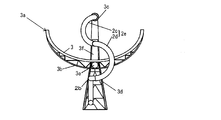
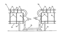
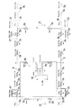
- FIG. 1 It is the schematic which shows a solar-heat collection system provided with the solar-heat collection apparatus which concerns on embodiment of this invention. It is a schematic front view which shows the heat collecting unit of the solar heat collecting device. It is a schematic side view which shows the connection part of two heat collection units of a solar heat collecting device. It is a circuit diagram for demonstrating the structure heated and supplied with an electric current through the heat-medium flow path of a solar-heat collection device.
- FIG. 1 shows a schematic configuration of a solar heat collecting system including the solar heat collecting apparatus 1 of the present embodiment.
- the solar heat collection system shown in FIG. 1 includes a plurality of solar heat collection devices 1.
- two solar heat collection devices 1 are illustrated, but actually, a large number (for example, 100 or more) of solar heat collection devices 1 are provided.
- the solar heat collected by the solar heat collection system is sent to the power generation system via a heat medium to generate power.
- These solar heat collection system and power generation system constitute a solar power generation plant.
- the solar heat collecting apparatus 1 has a substantially U-shaped heat medium flow path 2, and this heat medium flow path 2 is heated by sunlight condensed by a condenser mirror (light collecting means) 3. As a result, the temperature of the heat medium flowing through the heat medium flow path 2 rises to about 550 ° C., for example.
- a molten salt made of a mixture of sodium nitrate and potassium nitrate is used as the heating medium.
- FIG. 1 what is indicated by a small right triangle is a gradient symbol, and in accordance with this gradient symbol, the heat medium flow path 2 and an inclined pipe 5 described later are inclined with respect to the horizontal plane.
- the heat medium flow path 2 of the solar heat collecting apparatus 1 is connected to the inclined pipe 5.
- the inclined pipe 5 is configured in a loop shape, and the left end portion in FIG. 1 is higher than the right end portion. That is, the inclined pipe 5 is inclined to the lower right in FIG. 1 with respect to the horizontal plane.
- the inclined pipe 5 has two inclined pipes 5a and 5b arranged in parallel, and one inclined pipe 5a and the other inclined pipe 5b are connected to each other at both ends by pipes 5c. Yes.
- Two tanks 6 and 7 are connected to the inclined pipe 5. Each of the tanks 6 and 7 stores a heat medium.
- the tank 6 stores a heat medium before being heated by the solar heat collecting apparatus 1, and the tank 7 is a heat medium after being heated by the solar heat collecting apparatus 1. It comes to store. Therefore, hereinafter, the tank 6 is referred to as a cold side tank 6 and the tank 7 is referred to as a hot side tank 7.
- the cold side tank 6 and the inclined pipe 5a are connected by a connection pipe 10, and a heat medium is sent from the cold side tank 6 to the inclined pipe 5a by a pump (not shown) provided in the cold side tank 6. .
- the heat medium sent to the inclined pipe 5a branches at the connection portion between the connecting pipe 10 and the inclined pipe 5a, part of which flows to the right along the gradient of the inclined pipe 5a, and the remaining part of the inclined pipe 5a. It flows to the left against the gradient of 5a.
- the hot side tank 7 and the inclined pipe 5b are connected by a connection pipe 11, and the heat medium heated by the solar heat collecting device 1 is sent to the hot side tank 7 by the pressure of the pump. .
- the connection pipe 11 branches off in the middle, and a heat medium can be fed into the cold side tank 6 as necessary. For example, since the heat medium cannot be heated by the solar heat collecting device 1 at night when the sun does not come out, in that case, the heat medium is sent only to the cold side tank 6 by the switching valve provided in the branch part. The heating medium that is not heated is prevented from being fed into the hot side tank 7.
- one end of the heat medium flow path 2 of the solar heat collecting apparatus 1 is connected to the inclined pipe 5a, and the other end is connected to the inclined pipe 5b. Therefore, the heat medium flowing through the inclined pipe 5a during normal operation is a heat medium before being heated by the solar heat collecting apparatus 1, and the heat medium flowing through the inclined pipe 5b is a heat medium after being heated by the solar heat collecting apparatus 1. is there.
- the heat medium flow path 2 of the solar heat collecting apparatus 1 the heat medium flows from the end connected to the inclined pipe 5a to the end connected to the inclined pipe 5b, and the heat medium circulates through the solar heat collecting apparatus 1. It will be in the state.
- the vent portion 15 having a vent valve is provided at the highest position of the heat medium flow path 2, and by opening the vent valve of the vent portion 15, air is taken in when the heat medium is discharged. It has become.
- a heat collecting unit 3a is constituted by the condenser mirror 3 and the heat collecting tube 2a. As shown in FIGS. 2 and 3, the heat collecting unit 3 a heats the heat collecting medium 3 that collects sunlight to the heat collecting tube 2 a and the heat medium that flows inside by receiving the collected sunlight.
- the condensing mirror 3 has a substantially arc shape (concave shape) in cross section, extends to the left and right, and condenses sunlight on the straight tubular heat collecting tube 2a.
- the heat collection pipe 2a is provided with an outer pipe through which light flows and the heat medium flows inside.
- a vacuum is formed between the heat collecting tube 2a and the outer tube to form a vacuum heat insulating structure.
- the reinforcing member 3b is fixed to the back surface, which is the back side of the reflecting surface of the condensing mirror 3, and reinforces the condensing mirror 3.
- a plurality of reinforcing members 3b are provided at equal intervals along the length direction of the condenser mirror 3 and the heat collecting tube 2a.
- the reinforcing member 3b is fixed to the rotating cylinder 3e and can rotate integrally with the rotating cylinder 3e, so that the angle of the condensing mirror 3 can be changed in response to changes in the altitude of the sun.
- the tube support member 3c is fixed to the reinforcing member 3b and can rotate integrally with the rotary cylinder 3e while supporting the heat collecting tube 2a.
- the leg member 3d rotatably supports the condensing mirror 3, the heat collecting tube 2a, the reinforcing member 3b, and the tube support member 3c by rotatably supporting the rotating cylinder 3e.
- the pipe 2b is connected to the heat collecting pipe 2a via a flexible pipe (first flexible pipe) 2c and a flexible pipe (second flexible pipe) 2d, respectively.
- a flexible tube 2c connected to the heat collecting tube 2a As shown in FIG. 3, between the two heat collecting units 3a, a flexible tube 2c connected to the heat collecting tube 2a, a flexible tube 2d connected to the flexible tube 2c, and a pipe 2b connected to the flexible tube 2d.
- the flexible pipe 2d connected to the pipe 2b, the flexible pipe 2c connected to the flexible pipe 2d, and the heat collecting pipe 2a connected to the flexible pipe 2c are arranged, and the heat medium flow path 2 is constituted by these pipes. It has come to be. Since the two heat collecting units 3a are provided on the slope, the right heat collecting unit 3a is lower than the left heat collecting unit 3a.
- the two flexible pipes 2c and 2d connected in series are joined to each other in a state of being supported by a flexible support member 3f that is rotatably attached to the reinforcing member 3b or the rotating cylinder 3e.
- One flexible tube 2c is connected to the flexible tube 2d with one end connected to the heat collecting tube 2a and the other end supported by the flexible support member 3f. Therefore, the flexible tube 2c rotates integrally with the rotating cylinder 3e together with the heat collecting tube 2a and the flexible support member 3f.
- the flexible tube 2c is deformed according to expansion and contraction based on the temperature of the heat collecting tube 2a, and absorbs deformation due to expansion and contraction of the heat collecting tube 2a.
- the other flexible tube 2d is connected to the flexible tube 2c in a state where one end is supported by a flexible support member 3f that rotates integrally with the rotating cylinder 3e, and the other end is connected to a fixed pipe 2b. It deforms based on the movement of the heat collecting tube 2a corresponding to the altitude, and absorbs the displacement caused by the rotational movement of the heat collecting tube 2a.
- These flexible pipes 2c and 2d are made of a well-known metal such as stainless steel having heat resistance corresponding to the temperature of the heat medium.
- the heat collecting pipe 2a and the pipe 2b are also made of metal having heat resistance, and the flexible pipes 2c and 2d, the heat collecting pipe 2a, and the pipe 2b have conductivity.
- FIG. 1 four heat collecting units 3 a constituting one solar heat collecting device 1 are connected in series by a U-shaped heat medium flow path 2. Each heat collecting unit 3a is connected by a pipe 2b.
- the number of the heat collecting units 3a constituting the solar heat collecting apparatus 1 is not limited to four, and may be more or less than four.
- the heat collecting unit 3a is arrange
- the heat medium flow path 2 is caused to generate heat by flowing electricity directly to the heat medium flow path 2 composed of the heat collecting pipe 2a made of metal, the flexible pipes 2c and 2d, and the pipe 2b. Heating. Therefore, it is possible to heat the heat medium flow path 2 simply by connecting the power supply 30 and flowing current without attaching a heating device such as a heating wire to the outer periphery of the heat collecting pipe 2a or the flexible pipe 2c. .
- the power source 30 that supplies current to the heat medium flow path 2 serves as a heating unit.
- the heating device in the heat collecting pipe 2a does not interfere with heat reception by light collection. Further, it is not necessary to attach a heating device to the deformable flexible tubes 2c and 2d, and the heating medium flow path 2 can be heated with a very simple configuration.
- a heating method is, for example, Joule effect heating (impedance heating).
- FIG. 4 shows a circuit diagram when a current is supplied from the power supply (transformer) 30 to the heat medium flow path 2 in one solar heat collecting apparatus 1.
- a heat collecting pipe 2a, a pipe 2b, a flexible pipe 2c and a flexible pipe 2e composed of a flexible pipe 2d, a bypass cable (bypass electric circuit, power transmission cable) 2f and a closed circuit cable (described later) Wiring) 2g and power connection cable (wiring) 2h are shown by resistance symbols.
- the capacity of the power source is described as S (kVA), but a transformer having a necessary capacity may be used according to various conditions.
- the power source 30 is, for example, a transformer that transforms a single-phase 400V AC current to a voltage of about 30V, and is a floating power source in which the neutral point on the secondary coil side is not grounded.
- a power connection cable 2 h is connected from the power source 30 to the heat medium flow path 2.
- the heating medium flow path 2 is bent in a U shape as described above, so that the predetermined part on the upstream side and the predetermined part on the downstream side of the heating medium flow path 2 are arranged in parallel to each other. Yes.
- two heat collecting units 3a each including the condensing mirror 3 and the heat collecting pipe 2a are arranged on the upstream side and the downstream side of the heat medium flow path 2, respectively.
- one power source is provided for a portion (block) of one upstream heat collecting unit 3a and one downstream heat collecting unit 3a arranged side by side in the upstream heat collecting unit 3a.
- the current flows from 30. Therefore, in this embodiment, two heat collecting units are provided for each of the upstream predetermined portion and the downstream predetermined portion of the U-shaped heat medium flow path 2 of one solar heat collecting apparatus 1 arranged in parallel with each other.
- one block is formed from one adjacent heat collecting unit 3a (heat collecting pipe 2a) on the upstream side and one heat collecting unit 3a (heat collecting pipe 2a) on the downstream side. As a result, two blocks are formed in the heat medium flow path 2.
- the number of the heat collection units 3a included in one block can be arbitrarily changed according to the length and the number of the heat collection units 3a.
- the upstream side and the downstream side of the heat medium flow path 2 are arranged in parallel with each other, and for example, from the left side, the fixed pipe 2b, the flexible pipe 2e, the heat collecting pipe 2a, Various pipes are connected in series in the order of the flexible pipe 2e and the pipe 2b.
- the upper heat medium flow path 2 in the figure is the upstream side of the heat medium flow path 2
- the lower heat medium flow path 2 in the figure is the downstream side of the heat medium flow path 2.
- the heat collecting tube 2a is, for example, about 100m in total and is basically covered with an outer tube for vacuum insulation, but the divided body of the heat collecting tube 2a having about 12m of outer tubes is divided into 8 pieces. Are connected.
- a power source can be directly connected to the heat collecting tube 2a in the outer tube.
- a power connection cable 2h extending from the power source 30 to each of the two heat collecting tubes 2a in the block is connected to a connecting portion between the divided bodies of the heat collecting tubes 2a at the center of the heat collecting tube 2a.
- the upstream portion and the downstream portion of the heat medium flow path 2 are connected by a closed circuit cable 2g at a portion of the pipe 2b connected to the left and right of the heat collection pipe 2a of the heat collection unit 3a via the flexible pipe 2e. It is in the state.
- the power supply 30 is a floating power supply, whereas the closed circuit cable 2g is grounded by the ground 31.
- the power supply connection cable 2h heading upward in the figure from the power supply 30 is connected to, for example, the central portion of the heat collecting pipe 2a on the upstream side of the heat medium passage 2.
- a pair of left and right heat collecting tubes 2 a are connected to the upstream side and the downstream side of the heat medium flow path 2, respectively. This is because one heat collecting tube 2 a is divided at the central portion. It is described, and shows a state in which a power connection cable 2h is connected to the center of one heat collecting tube 2a.
- the power connection cable 2h heading upward is branched to the left and right at the portion connected to the heat collecting tube 2a, and current flows in parallel from left to right from this portion. Since the left and right parts of one block have the same structure, the left part of the block will be described here, and the description of the right part will be omitted.
- the current flowing from the power connection cable 2h extending upward flows to the left and right at the connection portion between the power connection cable 2h and the heat collecting tube 2a.
- the current flowing on the left side flows from the heat collecting tube 2a of the heat collecting unit 3a to the flexible tube 2e, flows in the order of the heat collecting tube 2a, the flexible tube 2e, and the pipe 2b, and then passes through the closed circuit cable 2g from the pipe 2b.
- the current flowing through the heat collection tube 2 a flows from the center of the heat collection tube 2 a to the lower power connection cable 2 h and reaches the power supply 30. Current also flows in the same order in the right part of the block.
- the heat collecting pipe 2a, the pipe 2b, and the flexible pipe 2e constituting the heat medium flow path 2 are different in material, cross-sectional area, length, and heat insulation structure, and when current flows in series at a constant voltage, respectively.
- the amount of heat generated based on the resistance value corresponding to the material, the cross-sectional area, and the length differs from the amount of heat released by the shape and the heat retaining structure. Therefore, when a current is simply passed in series, the amount of heat and the amount of heat released by the heat collecting pipe 2a, the pipe 2b, and the flexible pipes 2c and 2d are different, and there is a risk that a large difference in temperature occurs when the current is flowing. There is.
- the calorific value Joule heat
- H I 2 Rt.
- I the current value
- R the resistance value
- t time.
- the heat collection pipe 2a, the pipe 2b, the flexible pipe 2e, the closed circuit cable 2g, and the power connection cable 2h have a heat generation amount proportional to the respective resistance values. As shown in FIG.
- the resistance value of each resistor is Rt for the heat collecting pipe 2a, Rp for the pipe 2b, Rfp for the flexible pipe 2e, and Rc for the power connection cable 2h.
- the calorific value is calculated by multiplication. Therefore, if the actual resistance value of each member constituting the heat medium flow path 2 is known, the heat generation amount can be understood, but the temperature of each member is determined based on the heat generation amount and the heat dissipation amount. It is necessary to obtain the amount of heat generated or radiated from each member by experiment or simulation, or obtain the temperature of each member when a current is passed.
- the temperature of the pipe 2b is higher than the temperature of the heat collection pipe 2a and the flexible pipe 2e in the heat collection pipe 2a, the pipe 2b, and the flexible pipe 2e.
- the heat insulation structure is superior to the heat collection pipe 2a and the flexible pipe 2e, so that the amount of heat radiation is small and the temperature is likely to rise.
- the end of the pipe 2b connected to the flexible pipe 2e in order to reduce the value of the current flowing through the pipe 2b that is higher than the temperature of the flexible pipe 2e and the heat collecting pipe 2a.
- the bypass cable 2f is connected from the portion to the portion connected to the closed circuit cable 2g. That is, the pipe 2b and the bypass cable 2f are arranged in parallel, and the current flows separately into the pipe 2b and the bypass cable 2f, so that the value of the current flowing through the pipe 2b is reduced.
- the amount of heat generated in the pipe 2b is reduced, and the temperature of the pipe 2b can be brought closer to the heat collecting pipe 2a and the flexible pipe 2e.
- the heat collecting channel 2a occupies most of the heat medium flow path 2, and basically the voltage and current are set so that the heat collecting tube 2a is in a suitable temperature range.
- the value of the current flowing through the pipe 2b is reduced by connecting the bypass cable 2f in parallel with the pipe 2b as described above. At this time, the value of the current flowing to the bypass cable 2f side is determined by the resistance value Rp of the pipe 2b and the resistance value Rbc of the bypass cable 2f.
- the same current is used to bring the heat collecting pipe 2a, the flexible pipe 2e, and the pipe 2b to optimum temperatures.
- the value of the current flowing through the pipe 2b is set so that the temperature of the pipe 2b having the highest temperature when flowing is substantially the same as that of the heat collecting pipe 2a and the flexible pipe 2e, and the bypass cable 2f Determine the resistance value.
- the resistance value is determined by the material (the resistivity), the cross-sectional area, and the length of the bypass cable 2f, and is, for example, the low efficiency (specific resistance) multiplied by the length and divided by the cross-sectional area.
- the resistance value necessary for the bypass cable 2f is estimated, and the resistance value is set by the length of the bypass cable 2f, for example. It is preferable that the length of the bypass cable 2f is not shorter than the length of the bypassed portion of the pipe 2b, and the corresponding cross-sectional area of the conductive wire to be the above-described bypass cable 2f (the conductive wire multiplied by the cross-sectional area of one conductive wire) It is necessary to determine the number of Since the bypass cable 2f is longer than the bypassed portion of the pipe 2b, for example, the longer portion of the bypass cable 2f than the bypassed portion of the pipe 2b is stored in a case, for example. Is preferred.
- bypass cable 2f when the bypass cable 2f is bundled in the case, it is not in a state of being wound around a cable reel (coiled), but for example, in a long case of 1 m or longer, the longer diameter side becomes longer along the inner wall of the case. Thus, it is preferable that the winding is performed with a small number of windings.
- the value of the electric current which flows into the piping 2b can be changed so that it may differ from the heat collecting pipe 2a and the flexible pipe 2e. it can.
- a bypass cable 2f is arranged in parallel to the flexible tube 2e so that the flexible tube 2e The amount of current flowing is less than the amount of current flowing through the heat collection tube 2a , or conversely, a bypass cable 2f is arranged in parallel on the heat collection tube 2a side so that the amount of current flowing through the heat collection tube 2a is less than the amount of current flowing through the flexible tube 2e. May be.
- a solar heat collecting apparatus 1 at the time of start-up, when the molten salt as the heat medium is introduced into the heat medium flow path 2, or when the molten salt is discharged from the heat medium flow path 2 at the time of maintenance, maintenance is performed.
- the heat medium flow path 2 can be heated to prevent the molten salt from solidifying.
- the heat collecting tube 2a includes the heat collecting tube 2a as a structure that does not block the concentrated solar heat or a structure that can heat the heat collecting tube 2a even if there is a vacuum heat insulating structure on the outer periphery of the heat collecting tube 2a. Since a structure in which a current is directly passed through the heat medium passage 2 is employed, the heat collecting tube 2a can be heated with an extremely simple structure.
- a heating wire that follows the deformation of the flexible pipe 2e. It is possible to heat the flexible tube 2e by flowing an electric current without using the, so that the flexible tube 2e can be heated with a simple structure.
- the heat collecting pipe 2a, the flexible pipe 2e, and the pipe 2b which have different resistance values and heat dissipation amounts due to differences in the heat insulation structure, are connected in series to the heating medium flow path 2 that heats by supplying electricity, respectively. Based on the fact that the same current flows, a large temperature difference may occur between the tubes during heating. For example, the temperature is parallel to the pipe 2b where the temperature is higher than that of the heat collecting pipe 2a or the flexible pipe 2e.
- the bypass cable 2f it is possible to reduce the amount of current flowing through the pipe 2b from the amount of current flowing through the heat collecting tube 2a and the flexible tube 2e while being arranged in series.
- a current is passed in series based on the presence or absence of the bypass cable 2f and the resistance value of the bypass cable 2f.
- the temperature of each member can be set individually, and the temperature of each member can be set to be close to each other.
- the portions of the heat medium flow path 2 including the heat collecting pipes 2a that are arranged substantially in parallel with each other are arranged substantially in parallel with each other with a closed circuit cable (power transmission cable) 2g and a power connection cable (power transmission cable). 2h is connected to 2h to form a closed circuit for supplying current to the heat medium flow path 2. If the distance between the heat collecting tubes 2a arranged in parallel to each other is short, a power transmission cable for forming the closed circuit Can be shortened. Thereby, the installation work of the power transmission cable can be facilitated, and the cost and power transmission loss of the power transmission cable can be reduced.
- the flexible tube 2e is mainly deformed according to expansion and contraction based on the temperature of the heat collecting tube 2a, and the flexible tube 2d is connected to the flexible tube 2c and mainly deformed according to the movement of the heat collecting tube 2a. It has become. That is, the flexible tube 2e is divided into a portion that deforms corresponding to the expansion and contraction of the heat collecting tube 2a and a portion that deforms corresponding to the movement of the heat collecting tube 2a. It is possible to prevent a problem from being easily caused by the flexible tube 2e hitting a surrounding member in a state where electricity is passed and the portion where 2e freely deforms becomes long. In addition, it is preferable that the part to which the first flexible tube 2c and the second flexible tube 2d are joined is in a state of moving integrally with the heat collecting tube 2a.
- the bypass cable 2f as a bypass circuit is composed of a power transmission cable, and is provided with an insulating layer and a protective cover around the conductor, and can be easily used outdoors, has a low resistance value, and has a long length. Since it can be set freely, it is easy to set the resistance value finely. Moreover, the power transmission cable is relatively easy to bend, and even if it is long, it can be disposed relatively compactly in accordance with the installation location.
- the power supply 30 is provided in each of the two blocks including the two heat collecting units 3a so that a current flows through the heat medium flow path 2. It has a structure.
- the two heat collecting units 3a of one block are divided into two parts so that current flows in parallel.
- a power source 30 may be arranged for each heat collecting unit 3a to allow current to flow, or the two heat collecting units 3a in one block are divided into two parts and not connected in parallel to the power source 30. You may connect the power supply 30 so that it may be in series with the heat-medium flow path 2 of each of the two heat collection units 3a.
Landscapes
- Engineering & Computer Science (AREA)
- Chemical & Material Sciences (AREA)
- Combustion & Propulsion (AREA)
- Sustainable Development (AREA)
- Sustainable Energy (AREA)
- Life Sciences & Earth Sciences (AREA)
- Mechanical Engineering (AREA)
- General Engineering & Computer Science (AREA)
- Thermal Sciences (AREA)
- Physics & Mathematics (AREA)
- Pipe Accessories (AREA)
- Rigid Pipes And Flexible Pipes (AREA)
- Photovoltaic Devices (AREA)
Abstract
複数種の管からなる熱媒流路を効率的に加熱することが可能な太陽熱収集装置を提供する。 太陽熱収集装置(1)は、太陽熱を集光する集光鏡(3)の集光位置に熱媒を流す熱媒流路(2)を備える。熱媒流路(2)は、集光鏡(3)の集光位置に配置される集熱管(2a)を含む複数種の導電性の管が直列に接続されることにより構成される。直列に接続された集熱管(2a)、フレキシブル管(2e)、配管(2b)に直列に電気を流すことにより、これらを加熱する加熱手段(30)を備える。配管(2b)には、配管(2b)に対して電流が並列に流れるバイパスケーブル(2f)が設けられている。
Description
本発明は、熱媒が流れる熱媒流路を備える太陽熱収集装置に関する。
再生可能エネルギーを利用した効率的な電力安定供給を実現するためのシステムの一例として、太陽熱を利用した太陽熱発電プラントが挙げられる(例えば特許文献1および2参照)。
この太陽熱を利用した発電プラントでは、太陽熱を太陽熱収集装置で集め、この集めた熱を、熱媒を介して熱交換器に送り、この送った熱により水を蒸気に変化させ、この蒸気によりタービンを駆動させて発電を行うようになっている。太陽熱収集装置は、例えば、断面が凹状で水平方向に同形状で延在する集光(集熱)用の反射鏡(集光鏡)と、この反射鏡による集光位置に配置されて内部に熱媒が流れる(循環する)集熱管(受熱管:レシーバチューブ)とを有する集熱ユニットを備えるとともに、複数の集熱管を繋ぐための配管が設けられている。また、集熱管は、太陽の高度(仰角)の経時変化に対応して反射鏡とともに移動する。また、集熱管は、日中と夜間や、作動時とメンテナンス時の温度差により比較的大きく伸縮する。したがって、熱媒流路の固定された配管と、集熱管との間をフレキシブル管で接続することが考えられる。
この太陽熱を利用した発電プラントでは、太陽熱を太陽熱収集装置で集め、この集めた熱を、熱媒を介して熱交換器に送り、この送った熱により水を蒸気に変化させ、この蒸気によりタービンを駆動させて発電を行うようになっている。太陽熱収集装置は、例えば、断面が凹状で水平方向に同形状で延在する集光(集熱)用の反射鏡(集光鏡)と、この反射鏡による集光位置に配置されて内部に熱媒が流れる(循環する)集熱管(受熱管:レシーバチューブ)とを有する集熱ユニットを備えるとともに、複数の集熱管を繋ぐための配管が設けられている。また、集熱管は、太陽の高度(仰角)の経時変化に対応して反射鏡とともに移動する。また、集熱管は、日中と夜間や、作動時とメンテナンス時の温度差により比較的大きく伸縮する。したがって、熱媒流路の固定された配管と、集熱管との間をフレキシブル管で接続することが考えられる。
また、太陽熱収集装置で集めた熱は、熱媒を介して蓄熱装置により蓄熱することができ、この蓄熱した熱を、夜間といった太陽熱を収集できないない時間帯に再び熱媒を介して熱交換器に送ることにより、発電を行うことができる。このため、電力を安定的に供給することが可能となる。
このような太陽熱発電プラントで使用される熱媒としては、一般的に合成オイルが使用されるが、近年において、熱媒を合成オイルから溶融塩に変更する試みが為されている。
熱媒を合成オイルから溶融塩に変更することで以下のような利点がある。
まず、従来型より高温のスチームを供給することができ、これによって、発電効率の上昇と発電コストの削減が期待できる。また、従来型と比べ、溶融塩を熱媒として使用したシステムでは蓄熱装置のタンクの容量をより小さくすることができる。さらに、合成オイルを熱媒に用いた従来型は、蓄熱媒体として溶融塩を使用しているため、合成オイルと溶融塩の熱交換が必要であったが、全システムを溶融塩のみで動かすことにより熱交換器が不要となり、プラントをよりシンプルに構成することができるようになる。
熱媒を合成オイルから溶融塩に変更することで以下のような利点がある。
まず、従来型より高温のスチームを供給することができ、これによって、発電効率の上昇と発電コストの削減が期待できる。また、従来型と比べ、溶融塩を熱媒として使用したシステムでは蓄熱装置のタンクの容量をより小さくすることができる。さらに、合成オイルを熱媒に用いた従来型は、蓄熱媒体として溶融塩を使用しているため、合成オイルと溶融塩の熱交換が必要であったが、全システムを溶融塩のみで動かすことにより熱交換器が不要となり、プラントをよりシンプルに構成することができるようになる。
ところで、太陽熱収集装置に熱媒としての溶融塩を流している(循環させる)上述の集熱管を含む熱媒流路は、ポンプにより熱媒を流しているが、例えば、スタートアップの際に熱媒流路に溶融塩を導入する場合やメンテナンス時等に溶融塩を排出して再導入する場合には、蓄熱装置を含む熱媒流路を溶融塩が完全には循環していない状態となり、かつ、溶融塩への熱供給が途絶えた状態となる虞がある。このような状態の熱媒流路内で溶融塩の温度が下がり過ぎて凝固しないように熱媒流路を加熱装置で加熱する必要がある。溶融塩は、合成オイルと比較して凝固点が高く、熱が供給されない状態で放熱してしまうと凝固して、熱媒流路を閉塞させる虞がある。
太陽熱発電プラントの太陽熱収集装置以外の部分で固定配置された熱媒流路となる配管には、その外周側に上述の加熱装置として例えば電熱線(電気ヒートトレース)が設けられている。
しかし、太陽熱収集装置において、熱媒流路の多くの部分を占める集熱管は、外周部に真空断熱部を備えるので電熱線を配置することが困難である。また、電熱線が集光された太陽光の受光の邪魔になる虞がある。さらに、集熱管が上述のように移動するので、電熱線に電力を供給する構造が煩雑になる虞がある。また、フレキシブル管は、上述のように太陽の高度の変化に対応する移動や温度変化による集熱管の長さの変化に応じて変形するので、電熱線を取り付けることが難しい。したがって、太陽熱収集装置の熱媒流路を加熱することが難しく、熱媒流路を加熱するために大きなコストがかかる虞がある。
しかし、太陽熱収集装置において、熱媒流路の多くの部分を占める集熱管は、外周部に真空断熱部を備えるので電熱線を配置することが困難である。また、電熱線が集光された太陽光の受光の邪魔になる虞がある。さらに、集熱管が上述のように移動するので、電熱線に電力を供給する構造が煩雑になる虞がある。また、フレキシブル管は、上述のように太陽の高度の変化に対応する移動や温度変化による集熱管の長さの変化に応じて変形するので、電熱線を取り付けることが難しい。したがって、太陽熱収集装置の熱媒流路を加熱することが難しく、熱媒流路を加熱するために大きなコストがかかる虞がある。
本発明は、上記事情に鑑みて為されたもので、複数種の管からなる熱媒流路を効率的に加熱することが可能な太陽熱収集装置を提供することを目的とする。
前記課題を解決するために、本発明の太陽熱収集装置は、太陽熱を集光する集光手段の集光位置に熱媒を流す熱媒流路を備える太陽熱収集装置であって、
前記熱媒流路は、前記集光手段の集光位置に配置される集熱管を含む複数種の導電性の管が直列に接続されることにより構成され、
直列に接続された複数種の前記管に前記熱媒流路に沿って直列に電気を流すことにより、前記熱媒流路の前記管を発熱させる加熱手段が設けられ、
かつ、複数種の前記管のうちの少なくとも1つの前記管に当該管に対して電流が並列に流れるバイパス電路が設けられていることを特徴とする。
前記熱媒流路は、前記集光手段の集光位置に配置される集熱管を含む複数種の導電性の管が直列に接続されることにより構成され、
直列に接続された複数種の前記管に前記熱媒流路に沿って直列に電気を流すことにより、前記熱媒流路の前記管を発熱させる加熱手段が設けられ、
かつ、複数種の前記管のうちの少なくとも1つの前記管に当該管に対して電流が並列に流れるバイパス電路が設けられていることを特徴とする。
このような構成によれば、熱媒流路に外部から熱媒流路を加熱する例えば電熱線等を設けることなく、熱媒流路に電流を流すことにより、熱媒流路を発熱させて加熱することができる。したがって、集熱管の外面に電熱線を設けた場合に、集光された太陽光の受光の邪魔になったり、集熱管の外周部分に透明な外管を有する真空断熱構造があることにより電熱線等の加熱装置を取り付けることが困難だったりする場合でも直接集熱管に電流を流して発熱させることにより、集熱管を加熱することが可能になる。
また、フレキシブル管のように使用時に大きく変形する可能性があることにより、電熱線等の加熱装置を外付けすることが困難な管でも電流を流して加熱することができる。
また、個々の異なる種類の管にそれぞれ電流を流すのではなく、直列に繋がる複数種の管に直列に電流を流す構成とすることで、さらに各管を加熱するための構造を簡略化することできる。しかし、抵抗値の違う異なる種類の管に直列に電流を流した場合に、種類の異なる各管を流れる電流量は同じになってしまう。この場合に管の種類(材質および形状)の違いによって抵抗値が異なることになり、管の種類によって発熱量が異なることになる。また、熱媒の温度は、周囲の温度に対して高温であることから熱媒流路は熱が逃げないように断熱構造とすることが好ましい。この際に、各管はその構造や使用状況によって異なる断熱構造が採用され、それぞれ断熱性能が異なることから各管は種類によって放熱量が異なることになる。
これら異なる種類の複数の管に直列に電流を流して加熱すると、各管によって加熱時の温度が大きく異なる状態となってしまう虞がある。そこで、他の種類の管より加熱時の温度が高くなる種類の管に当該管と並列に電流が流れるバイパス電路を設けることで、加熱時に当該管に流れる電流量を減少させて当該管の過加熱を防止することが可能となる。
以上のことから、種類の異なる複数の管に直列に電流を流す簡単な構造で、各種類の管を適切な温度に加熱することができる。したがって、熱媒流路を低コストに加熱することができる。
本発明の前記構成において、前記熱媒が溶融塩であることが好ましい。
このような構成によれば、熱媒としての溶融塩が熱媒流路で凝固するのを防止できる。なお、溶融塩の凝固点温度(融点温度)は、常温に対してかなり高く、集光手段に光を照射され高温の状態で熱媒流路を循環している状態や、蓄熱槽等で蓄熱された熱を利用して熱媒流路を循環している状態であれば、温度が低下し過ぎて凝固することはない。しかし、スタートアップやメンテナンスで熱媒流路に溶融塩を導入したり、熱媒流路から溶融塩を排出したりする場合に、熱の供給が途絶えた状態で溶融塩が熱媒流路を流れる場合に途中で溶融塩が凝固する虞がある。そこで、熱媒流路を加熱することにより、溶融塩の凝固を防止できる。なお、溶融塩以外でも熱媒として凝固点温度の高い物質や、冷えると粘性が高くなるような物質を用いる場合にも適用可能である。
また、本発明の前記構成において、前記管には、太陽高度に対応して移動する前記集熱管と、固定の配管と、前記集熱管と前記配管とを繋ぐフレキシブル管とが含まれることが好ましい。
この場合に、電熱線等の外付けの加熱装置を用いることが上述のように難しい集熱管およびフレキシブル管を簡単な構造で容易に加熱することができる。
また、本発明の前記構成において、前記配管に前記バイパス電路が設けられていることが好ましい。
このような構成によれば、配管は、フレキシブル配管のように変形することがなく、また、集熱管のように太陽光が照射されることもないので、低コストで高い断熱性能を有する断熱構造を採用することができる。したがって、配管は、抵抗値がそれほど高くなくとも、電流を流した場合に、放熱量が少ないことから高温になる虞がある。そこで、配管にバイパス電路を設けて配管を流れる電流量を減少させることで、配管がフレキシブル管や集熱管に対して高温に成り過ぎるのを防止することができる。
また、本発明の前記構成において、前記バイパス電路において電流が流れる導電体の材質と、断面積と、長さとのうちの少なくとも1つを調整することにより、前記バイパス電路の抵抗値が調整されていることが好ましい。
このような構成によれば、バイパス電路と並列に配置された管の電流量を容易に調整することができる。特に、伝導体の長さにより抵抗値を調整するものとすれば、抵抗値の調整がより容易になる。なお、伝導体の材質によって抵抗率(比抵抗)が異なることにより、抵抗値を調整することができる。
また、本発明の前記構成において、前記熱媒流路に熱媒を導入する場合および前記熱媒流路から熱媒を排出する場合に、前記加熱手段は、前記管に電流を流して、前記熱媒流路を加熱することが好ましい。
このような構成によれば、熱媒の熱媒流路への導入と熱媒流路からの排出の場合に、高温の熱媒が熱媒流路を循環している状態とならず、熱媒が途中で冷えて凝固する虞があるが、この場合に熱媒の凝固を確実に防止することができる。
また、本発明の前記構成において、前記熱媒流路は、2つの所定部分が互いに略平行に配置され、
2つの前記所定部分のそれぞれに前記集熱管が配置されるとともに、一方の前記所定部分の前記集熱管と、他方の前記所定部分の前記集熱管とが互いに略平行に隣り合って配置され、
前記熱媒流路の2つの前記所定部分を配線で繋ぐことにより、互いに略平行に配置される2つの前記集熱管を含む回路が構成され、前記加熱手段は前記回路に電流を流すことが好ましい。
2つの前記所定部分のそれぞれに前記集熱管が配置されるとともに、一方の前記所定部分の前記集熱管と、他方の前記所定部分の前記集熱管とが互いに略平行に隣り合って配置され、
前記熱媒流路の2つの前記所定部分を配線で繋ぐことにより、互いに略平行に配置される2つの前記集熱管を含む回路が構成され、前記加熱手段は前記回路に電流を流すことが好ましい。
このような構成によれば、熱媒流路の互いに略平行に配置される所定部分間の距離が短ければ、熱媒流路に電流を流す閉回路を構成するための送電用ケーブルの長さを短くすることができる。これにより、送電用ケーブルの設置作業を容易にすることができるとともに、送電用ケーブルにかかるコストや、送電ロスを低減することができる。なお、略直線状に複数の集熱管が連結された熱媒流路の長い部分に電流を流すために、熱媒流路の電流を流す部分の端と端を送電用ケーブルで繋ぐと、少なくとも熱媒流路の電流を流す部分と略同じ長さの送電用ケーブルが必要となる。
本発明によれば、複数の種類の管から構成される熱媒流路に電気を流して発熱させることにより、導電性の管ならばどのような管であっても簡単な構造で加熱可能となるとともに、複数種類の管からなる熱媒流路に直列に電流を流した場合でも管によって温度が高く成り過ぎるのを防止できる。
以下、本発明の実施の形態を、図面を参照して説明する。
図1は、本実施の形態の太陽熱収集装置1を備える太陽熱収集システムの概略構成を示すものである。図1に示す太陽熱収集システムは、複数の太陽熱収集装置1を備えている。なお、図1では太陽熱収集装置1を2つ記載しているが、実際には太陽熱収集装置1は多数(例えば100台以上)設けられている。なお、太陽熱収集システムで収集された太陽熱は、熱媒を介して発電システムに送られて発電が行われる。これら太陽熱収集システムと発電システムとから太陽熱発電プラントが構成される。
図1は、本実施の形態の太陽熱収集装置1を備える太陽熱収集システムの概略構成を示すものである。図1に示す太陽熱収集システムは、複数の太陽熱収集装置1を備えている。なお、図1では太陽熱収集装置1を2つ記載しているが、実際には太陽熱収集装置1は多数(例えば100台以上)設けられている。なお、太陽熱収集システムで収集された太陽熱は、熱媒を介して発電システムに送られて発電が行われる。これら太陽熱収集システムと発電システムとから太陽熱発電プラントが構成される。
太陽熱収集装置1は、略U形の熱媒流路2を有しており、この熱媒流路2は、集光鏡(集光手段)3で集光された太陽光によって加熱され、これによって、熱媒流路2を流れる熱媒の温度が例えば550℃程度まで上昇するようになっている。
なお、本実施の形態では熱媒としては、硝酸ナトリウムと硝酸カリウムとの混合物からなる溶融塩が使用されている。
また、図1において、小さな直角三角形で示すものは勾配記号であり、この勾配記号にしたがって、熱媒流路2および後述する傾斜配管5が水平面に対して傾斜している。
また、図1において、小さな直角三角形で示すものは勾配記号であり、この勾配記号にしたがって、熱媒流路2および後述する傾斜配管5が水平面に対して傾斜している。
太陽熱収集装置1の熱媒流路2は傾斜配管5に接続されている。傾斜配管5はループ状に構成されており、図1において左端部が右端部より高くなっている。つまり、傾斜配管5は水平面に対して図1において右下がりに傾斜している。また、傾斜配管5は、平行に配置された2本の傾斜配管5a,5bを有しており、一方の傾斜配管5aと他方の傾斜配管5bとはその両端部においてそれぞれ配管5cによって接続されている。
傾斜配管5には2つのタンク6,7が接続されている。タンク6,7はそれぞれ熱媒を貯留するものであり、タンク6は太陽熱収集装置1によって加熱される前の熱媒を貯留し、タンク7は太陽熱収集装置1によって加熱された後の熱媒を貯留するようになっている。したがって、以下ではタンク6をコールド側タンク6と称し、タンク7をホット側タンク7と称する。
傾斜配管5には2つのタンク6,7が接続されている。タンク6,7はそれぞれ熱媒を貯留するものであり、タンク6は太陽熱収集装置1によって加熱される前の熱媒を貯留し、タンク7は太陽熱収集装置1によって加熱された後の熱媒を貯留するようになっている。したがって、以下ではタンク6をコールド側タンク6と称し、タンク7をホット側タンク7と称する。
コールド側タンク6と傾斜配管5aとは接続配管10によって接続されており、コールド側タンク6に設けられた図示しないポンプによって、コールド側タンク6から傾斜配管5aに熱媒を送り込むようになっている。傾斜配管5aに送り込まれた熱媒は、接続配管10と傾斜配管5aとの接続部において分岐して、その一部が傾斜配管5aの勾配に沿って右側に流れ、残りの一部が傾斜配管5aの勾配に逆らって左側に流れるようになっている。
また、ホット側タンク7と傾斜配管5bとは接続配管11によって接続されており、太陽熱収集装置1によって加熱された後の熱媒を前記ポンプの圧力によってホット側タンク7に送り込むようになっている。なお、接続配管11は途中で分岐して、コールド側タンク6にも必要に応じて熱媒を送り込むことが可能となっている。例えば、太陽が出ていない夜間等は太陽熱収集装置1にて熱媒を加熱できないので、その場合、前記分岐部に設けられた切替弁によって、熱媒をコールド側タンク6にのみ送り込むようにして、加熱されていない熱媒がホット側タンク7に送り込まれるのを防止する。
また、太陽熱収集装置1の熱媒流路2の一方の端部は傾斜配管5aに接続されており、他方の端部は傾斜配管5bに接続されている。したがって、通常の運転時に傾斜配管5aを流れる熱媒は太陽熱収集装置1によって加熱される前の熱媒であり、傾斜配管5bを流れる熱媒は太陽熱収集装置1によって加熱された後の熱媒である。太陽熱収集装置1の熱媒流路2では、傾斜配管5aに接続された端部から傾斜配管5bに接続される端部に熱媒が流れることになり、熱媒が太陽熱収集装置1を循環している状態となる。
なお、熱媒流路2および傾斜配管5a,5bから熱媒を排出する場合には、熱媒流路2および傾斜配管5a,5bの傾斜にしたがって上から下に熱媒を流すことが可能になっており、熱媒流路2の最も高い位置にベント弁を備えるベント部15が設けられており、ベント部15のベント弁を開放することにより、熱媒を排出する場合に空気を取り入れるようになっている。
また、熱媒流路2の集光鏡3の部分が、集光鏡3で集光された光により加熱される集熱管2aとなる。これら集光鏡3と集熱管2aとから集熱ユニット3aが構成される。
図2および図3に示すように、集熱ユニット3aは、太陽光を集熱管2aに集光する集光鏡3と、集光された太陽光を受光することにより内部を流れる熱媒を加熱する当該集熱管2aと、集光鏡3を補強する補強部材3bと、前記補強部材3bに接続されて集光鏡3の集光位置に集熱管2aを支持する管支持部材3cと、集光鏡3を支持する脚部材3dと、脚部材3dに回転自在に支持されるとともに、補強部材3bに固定される回転筒3eとを備える。
図2および図3に示すように、集熱ユニット3aは、太陽光を集熱管2aに集光する集光鏡3と、集光された太陽光を受光することにより内部を流れる熱媒を加熱する当該集熱管2aと、集光鏡3を補強する補強部材3bと、前記補強部材3bに接続されて集光鏡3の集光位置に集熱管2aを支持する管支持部材3cと、集光鏡3を支持する脚部材3dと、脚部材3dに回転自在に支持されるとともに、補強部材3bに固定される回転筒3eとを備える。
集光鏡3は、断面略円弧状(凹状)で、左右に延在し、直管状の集熱管2aに太陽光を集光するようになっている。集熱管2aは、内部に熱媒が流れるとともに、外部に光を透過する外管が備えられている。集熱管2aと外管との間が略真空となって、真空断熱構造を構成している。補強部材3bは、集光鏡3の反射面の裏側となる背面に固定されて集光鏡3を補強する。補強部材3bは、集光鏡3および集熱管2aの長さ方向に沿って等間隔に複数設けられている。
また、補強部材3bは、回転筒3eに固定され、回転筒3eと一体に回転可能となっていることにより、集光鏡3を太陽の高度の変化に対応して角度変更可能としている。管支持部材3cは、補強部材3bに固定されるとともに集熱管2aを支持した状態で、回転筒3eと一体に回転可能となっている。脚部材3dは、回転筒3eを回転自在に支持することで、集光鏡3、集熱管2a、補強部材3b、管支持部材3cを回転自在に支持している。
また、集熱ユニット3aの左右端部では、それぞれ、集熱管2aに配管2bがフレキシブル管(第1のフレキシブル管)2cおよびフレキシブル管(第2のフレキシブル管)2dを介して接続されている。図3に示すように、2つの集熱ユニット3aの間では、集熱管2aに接続されたフレキシブル管2c、当該フレキシブル管2cに接続されたフレキシブル管2d、当該フレキシブル管2dに接続された配管2b、当該配管2bに接続されたフレキシブル管2d、当該フレキシブル管2dに接続されたフレキシブル管2c、当該フレキシブル管2cに接続された集熱管2aが配置され、これらの管により熱媒流路2が構成されるようになっている。なお、2つの集熱ユニット3aは、斜面上に設けられているため、左の集熱ユニット3aより、右の集熱ユニット3aの方が低くなっている。
直列に繋がれた2本のフレキシブル管2c、2dは、補強部材3bまたは回転筒3eに一体に回転可能に取り付けられたフレキ支持部材3fに支持された状態で互いに接合されている。一方のフレキシブル管2cは、一方の端部が集熱管2aに接続され、他方の端部がフレキ支持部材3fに支持された状態でフレキシブル管2dに接続されている。したがって、フレキシブル管2cは、集熱管2aおよびフレキ支持部材3fとともに、回転筒3eと一体に回転する。このフレキシブル管2cは、集熱管2aの温度に基づく伸縮に応じて変形し、集熱管2aの伸縮による変形を吸収するようになっている。
他方のフレキシブル管2dは、一方の端部が回転筒3eと一体に回転するフレキ支持部材3fに支持された状態でフレキシブル管2cに接続され、他端部が固定の配管2bに接続され、太陽高度に対応する集熱管2aの移動に基づいて変形し、集熱管2aの回転移動による変位を吸収するようになっている。これら、フレキシブル管2c、2dは、熱媒の温度に対応する耐熱性を有する周知のステンレス等の金属からなる。また、集熱管2aおよび配管2bも耐熱性を有する金属製であり、フレキシブル管2c、2d、集熱管2a、配管2bは、それぞれ導電性を有するものとなっている。
なお、図1において、1つの太陽熱収集装置1を構成する4つの集熱ユニット3aは、U字状の熱媒流路2により、直列に接続されており。各集熱ユニット3a間は、配管2bで接続されている。なお、太陽熱収集装置1を構成する集熱ユニット3aの数は4つに限定されるものではなく、4つより多くても少なくてもよい。また、本実施の形態では、上述のようにU字状の熱媒流路2を用いることにより、集熱ユニット3aは、2列に配置されるようになっている。
また、本実施の形態において、上述のように金属からなる集熱管2a、フレキシブル管2c,2dおよび配管2bからなる熱媒流路2に直接電気を流すことにより、熱媒流路2を発熱させて加熱するようになっている。したがって、集熱管2aや、フレキシブル管2cの外周に、電熱線等の加熱装置を取り付けることなく、電源30を接続して電流を流すだけで、熱媒流路2を加熱することが可能になる。すなわち、熱媒流路2に電流を流す電源30が加熱手段となる。この場合に、熱媒流路2自体が発熱することから、集熱管2aにおいて加熱装置が集光による受熱の邪魔になることがない。また、変形するフレキシブル管2c、2dに加熱装置を外付けする必要がなくなり、極めて簡単な構成で熱媒流路2の加熱が可能となる。このような加熱方法が、例えばジュール・エフェクト・ヒーティング(インピーダンス・ヒーティング)である。
図4に、1つの太陽熱収集装置1における熱媒流路2に電源(トランス)30から電流を流した場合の回路図を示す。回路図では、熱媒流路2の集熱管2a、配管2b、フレキシブル管2cおよびフレキシブル管2dからなるフレキシブル管2eと、後述するバイパスケーブル(バイパス電路、送電用ケーブル)2fおよび閉回路用ケーブル(配線)2g、電源接続ケーブル(配線)2hを抵抗の図記号で示した。また、図4において、電源の容量は、S(kVA)と記載しているが、各種条件に応じて必要な容量のトランスを用いればよい。
電源30は、例えば、単相400Vの交流電流を、30V程度の電圧に変圧するトランスであり、二次コイル側の中性点が接地されていないフローティング電源となっている。電源30から熱媒流路2に電源接続ケーブル2hが接続されている。本実施の形態では、上述のように熱媒流路2がU字状に曲げられることにより、熱媒流路2の上流側の所定部分と下流側の所定部分とが互いに平行に配置されている。また、熱媒流路2の上流側と下流側とにそれぞれ2個ずつ集光鏡3および集熱管2aからなる集熱ユニット3aが配置されている。
本実施の形態では、上流側の1つの集熱ユニット3aと、この上流側の集熱ユニット3aに並んで配置される下流側の1つの集熱ユニット3aとの部分(ブロック)に1つの電源30から電流を流す構造となっている。したがって、本実施例では、1つの太陽熱収集装置1のU字状の熱媒流路2の互いに平行に配置される上流側の所定部分と下流側の所定部分とに2つずつの集熱ユニット3aが設けられており、図1において、隣り合う上流側の1つの集熱ユニット3a(集熱管2a)と、下流側の1つの集熱ユニット3a(集熱管2a)とから1つのブロックが形成されることにより、熱媒流路2に2つのブロックが形成されている。なお、例えば、1つのU字状の熱媒流路2の上流側と下流側に3つずつの集熱ユニット3aが設けられていれば、3つのブロックが形成されることになる。なお、1つのブロックに含ませる集熱ユニット3aの数は、集熱ユニット3aの長さや数によって任意に変更することができる。
一つのブロックには、図4に示すように。上述のように互いに平行に熱媒流路2の上流側と下流側とが配置されており、上流側と下流側とにおいて、例えば、左側から固定の配管2b、フレキシブル管2e、集熱管2a、フレキシブル管2e、配管2bの順で各種管が直列に接続されている。なお、図4において、例えば、図中上側の熱媒流路2を熱媒流路2の上流側とし、図中下側の熱媒流路2を熱媒流路2の下流側とする。
集熱管2aは、例えば、全体で約100mであり、基本的に真空断熱用の外管に覆われた状態となっているが、12m程度ずつの外管を有する集熱管2aの分割体を8つ接続した状態となっている。これら集熱管2aの分割体の接続部では、外管の中の集熱管2aに直接電源が接続可能となっている。本実施の形態では、電源30からブロック内の2つの集熱管2aそれぞれに延びる電源接続ケーブル2hが集熱管2aの中央部で、集熱管2aの分割体同士の接続部に接続されている。また、熱媒流路2の上流部分と下流部分とは、集熱ユニット3aの集熱管2aの左右それぞれにフレキシブル管2eを介して接続された配管2bの部分で閉回路用ケーブル2gにより接続された状態となっている。また、上述のように電源30がフローティング電源なのに対して、閉回路用ケーブル2gの部分がグランド31により接地されている。
これにより、電源30から図中上に向かう電源接続ケーブル2hが例えば、熱媒流路2の上流側の集熱管2aの中央部に接続される。なお、図4において、熱媒流路2の上流側と下流側とでそれぞれ左右一対の集熱管2aが接続された状態となっているが、これは1つの集熱管2aを中央部で分けて記載したものであり、1つの集熱管2aの中央部に電源接続ケーブル2hが接続されている状態を示している。
上側に向かう電源接続ケーブル2hは、集熱管2aに接続された部分で左右に分岐し、この部分から左右に並列で電流が流れる。一つのブロックの左右の各部分は、同じ構造となっているので、ここでは、ブロックの左側部分を説明し、右側部分の説明を省略する。上に延びる電源接続ケーブル2hから流れる電流は、電源接続ケーブル2hと集熱管2aとの接続部で左右に流れる。左側を流れる電流は、集熱ユニット3aの集熱管2aからフレキシブル管2eに向かい、集熱管2a、フレキシブル管2e、配管2bの順で流れ、配管2bから閉回路用ケーブル2gを通って下側の配管2bに流れる。さらに、配管2bからフレキシブル管2e、集熱管2aに至る。集熱管2aを流れる電流は、集熱管2aの中央部から下側の電源接続ケーブル2hに流れ、電源30に至ることになる。上述のブロックの右側部分も同じ順で電流が流れる。
ここで、熱媒流路2を構成する集熱管2a、配管2b、フレキシブル管2eは、その材質、断面積、長さ、保温構造が異なり、それぞれ一定の電圧で直列に電流を流した場合に、材質と断面積と長さに対応する抵抗値に基づく発熱量と、形状や保温構造による放熱量が異なる。したがって、単純に直列に電流を流した場合に、集熱管2a、配管2b、フレキシブル管2c、2dで加熱される熱量と放熱量が異なり、電流を流している状態で温度に大きな差が出る虞がある。
ここで、発熱量(ジュール熱)は、H=I2Rtで表される。なお、Hが発熱量、Iが電流値、Rが抵抗値、tが時間である。
また、回路図で直列に並んだ各抵抗(集熱管2a、配管2b、フレキシブル管2e、閉回路用ケーブル2g、電源接続ケーブル2h)には、同じ電流が流れることになるので、各抵抗としての集熱管2a、配管2b、フレキシブル管2e、閉回路用ケーブル2g、電源接続ケーブル2hは、それぞれの抵抗値に比例した発熱量となる。図4に示すように、それぞれの抵抗の抵抗値は、集熱管2aがRt、配管2bがRp、フレキシブル管2eがRfp、電源接続ケーブル2hがRcとなり、これに電流値の2乗と時間を乗算することで発熱量が算出される。したがって、熱媒流路2を構成する各部材の実際の抵抗値が分かれば、発熱量が分かることになるが、各部材の温度は、発熱量と放熱量とに基づいて決まるので、例えば、実験またはシミュレーションにより、各部材の発熱量や放熱量を求めたり、電流を流した場合の各部材の温度を求めたりする必要がある。
また、回路図で直列に並んだ各抵抗(集熱管2a、配管2b、フレキシブル管2e、閉回路用ケーブル2g、電源接続ケーブル2h)には、同じ電流が流れることになるので、各抵抗としての集熱管2a、配管2b、フレキシブル管2e、閉回路用ケーブル2g、電源接続ケーブル2hは、それぞれの抵抗値に比例した発熱量となる。図4に示すように、それぞれの抵抗の抵抗値は、集熱管2aがRt、配管2bがRp、フレキシブル管2eがRfp、電源接続ケーブル2hがRcとなり、これに電流値の2乗と時間を乗算することで発熱量が算出される。したがって、熱媒流路2を構成する各部材の実際の抵抗値が分かれば、発熱量が分かることになるが、各部材の温度は、発熱量と放熱量とに基づいて決まるので、例えば、実験またはシミュレーションにより、各部材の発熱量や放熱量を求めたり、電流を流した場合の各部材の温度を求めたりする必要がある。
本実施の形態では、集熱管2a、配管2b、フレキシブル管2eにおいては、集熱管2aおよびフレキシブル管2eの温度に対して配管2bの温度が高くなることが確認された。外部から熱を得る必要がある集熱管2aや、変形するフレキシブル管2eに比較して、温度差による収縮はあるが、基本的に固定された状態で、かつ、外部と断熱しても問題がない配管2bでは、集熱管2aやフレキシブル管2eより断熱性能に優れた保温構造となっていることから放熱量が少なく、温度が上昇し易くなっている。
本実施の形態では、同じ電流を流した場合に、フレキシブル管2eや集熱管2aに対してより高温となる配管2bに流れる電流値を下げるために、配管2bのフレキシブル管2eに接続される端部から閉回路用ケーブル2gに接続される部分まで、バイパスケーブル2fを接続している。すなわち、配管2bとバイパスケーブル2fとは、並列に配置された状態となっており、電流が配管2bとバイパスケーブル2fとに分離して流れることにより、配管2bを流れる電流の値が低くなり、配管2bにおける発熱量が減少し、配管2bの温度を集熱管2aおよびフレキシブル管2eに近づけることができる。
なお、熱媒流路2において、多くの部分を占めるのは、集熱管2aであり、基本的には、集熱管2aが好適な温度範囲となるように、電圧や電流が設定されている。それに対して配管2bの温度が必要以上に高くなることから、上述のようにバイパスケーブル2fを配管2bと並列に接続することにより、配管2bを流れる電流の値を低下させる。この際に、バイパスケーブル2f側に流れる電流の値は、配管2bの抵抗値Rpと、バイパスケーブル2fの抵抗値Rbcによって決まる。すなわち、配管2bを流れる電流Ipは、配管2bおよびバイパスケーブル2fのそれぞれにかかる電圧をVpとするとIp=Vp/Rpとなり、バイパスケーブル2fを流れる電流Ibcは、Ibc=Vp/Rbcとなる。
本実施の形態においては、上述の実験(シミュレーション)により、電流を熱媒流路2に流した場合に、集熱管2a、フレキシブル管2e、配管2bを最適な温度にするために、同じ電流を流した場合に最も温度が高くなる配管2bの温度が、例えば、集熱管2aやフレキシブル管2eと略同じ温度となるように配管2bを流れる電流の値を設定し、それに合わせてバイパスケーブル2fの抵抗値を決定する。抵抗値は、バイパスケーブル2fの材質(の抵抗率)と断面積と長さによって決まるものであり、例えば、低効率(比抵抗)に長さを乗算して断面積で除算したものである。
基本的には、バイパスケーブル2fに必要な抵抗値を推測し、例えば、バイパスケーブル2fの長さで抵抗値を設定する。なお、バイパスケーブル2fの長さが配管2bのバイパスされる部分の長さより短くならないことが好ましく、それに対応して上述のバイパスケーブル2fとなる導線の断面積(一本の導線の断面積かける導線の本数)を決定しておく必要がある。なお、バイパスケーブル2fは、配管2bのバイパスされる部分より長くされるので、例えば、バイパスケーブル2fの配管2bのバイパスされる部分より長くなった部分は、例えば、ケース内に纏めて収納することが好ましい。但し、バイパスケーブル2fをケース内に纏める際にケーブル用リールに巻き取ったような状態(コイル状)ではなく、例えば、1m以上の長いケース内でケースの内壁に沿って長径側が長くなるようにして、少ない巻き数で巻いた状態とすることが好ましい。
このような構成とすることにより、直列に配置される集熱管2a、フレキシブル管2e、配管2bにおいて、配管2bに流れる電流の値を、集熱管2a、フレキシブル管2eと異なるように変更することができる。なお、例えば、電流を流した場合に集熱管2aよりフレキシブル管2eの方が、温度が高くなるような場合に、フレキシブル管2eに対して並列にバイパスケーブル2fを配置して、フレキシブル管2eに流れる電流量を集熱管2aに流れる電流量より少なくしたり、逆に集熱管2a側に並列にバイパスケーブル2fを配置して、集熱管2aに流れる電流量をフレキシブル管2eに流れる電流量より少なくしてもよい。
このような太陽熱収集装置1によれば、少なくともスタートアップの際に熱媒流路2に熱媒としての溶融塩を導入する場合や、メンテナンス時に熱媒流路2から溶融塩を排出する場合やメンテナンス後に溶融塩を熱媒流路2に再導入する場合に、熱媒流路2を加熱して、溶融塩が凝固するのを防止することができる。
この場合に、集熱管2aは、集光された太陽熱を遮えぎらない構造や、集熱管2aの外周部に真空断熱構造があっても集熱管2aを加熱できる構造として、集熱管2aを含む熱媒流路2に直接電流を流す構造を採用したので、極めて簡単な構造で集熱管2aを加熱することが可能となる。
また、集熱管2aの太陽高度に対応する移動と、温度変化による伸縮に対応するために熱媒流路2に設けられたフレキシブル管2eにおいても、フレキシブル管2eの変形に追随するような電熱線を用いることなく、フレキシブル管2eに電流を流して加熱可能であり、簡単な構造でフレキシブル管2eを加熱することが可能となる。
また、電気を流して加熱する熱媒流路2に、抵抗値が異なるとともに断熱構造の違いにより、放熱量が異なる集熱管2a、フレキシブル管2e、配管2bが直列に繋がれることにより、それぞれに同じ値の電流が流れてしまうことに基づいて、各管の間に、加熱時に大きな温度差が生じる可能性があるが、例えば、温度が集熱管2aやフレキシブル管2eより高くなる配管2bに並列にバイパスケーブル2fを配置することにより、直列配置でありながら、集熱管2aおよびフレキシブル管2eに流れる電流量より配管2bを流れる電流量を少なくすることが可能となる。これにより、バイパスケーブル2fを除いて、直列に配置される、集熱管2a、フレキシブル管2e、配管2bにおいて、バイパスケーブル2fの有無や、バイパスケーブル2fの抵抗値に基づいて、直列に電流を流した際のそれぞれの部材の温度を個別に設定することが可能となり、それぞれの部材の温度を互いに近づけるように設定することが可能となる。
また、互いに略平行に配置された集熱管2aを含む熱媒流路2の互いに略平行に配置される部分同士を閉回路用ケーブル(送電用ケーブル)2gと、電源接続ケーブル(送電用ケーブル)2hとで接続して熱媒流路2に電流を流す閉回路を構成しているので、互いに平行に配置される集熱管2a間の距離が短ければ、閉回路を構成するための送電用ケーブルを短くできる。これにより、送電用ケーブルの設置作業を容易にできるとともに、送電用ケーブルにかかるコストおよび送電ロスの低減を図ることができる。
また、フレキシブル管2eが、主に集熱管2aの温度に基づく伸縮に応じて変形するフレキシブル管2cと、フレキシブル管2cに接続され、主に集熱管2aの移動に応じて変形するフレキシブル管2dからなっている。すなわち、フレキシブル管2eを、集熱管2aの伸縮に対応して変形する部分と、集熱管2aの移動に対応して変形する部分に分けたので、これら2種類の変形に対応するためにフレキシブル管2eが自由に変形する部分が長くなって、電気を流した状態で周囲の部材にフレキシブル管2eが当たることなどによって問題が生じ易くなるのを防止することができる。なお、第1のフレキシブル管2cと第2のフレキシブル管2dとが接合される部分は、集熱管2aと一体に移動する状態となっていることが好ましい。
バイパス電路としてのバイパスケーブル2fは、送電用ケーブルからなるが、導電体の周囲に絶縁層と保護カバーが設けられており、屋外で容易に使用できるとともに、抵抗値が低く、かつ、長さを自由に設定できるので、抵抗値を細かく設定することが容易である。また、送電用ケーブルは、曲げることも比較的容易であり、長くなっても、設置場所に対応して比較的コンパクトに配置することができる。
なお、本実施の形態では、4つの集熱ユニット3aを備える太陽熱収集装置1において、2つの集熱ユニット3aを備える2つのブロックのそれぞれに電源30を設けて熱媒流路2に電流を流す構造としている。また、1つのブロックの2つの集熱ユニット3aをそれぞれ二分して、並列に電流を流すようにしている。それに対して、1つの集熱ユニット3a毎に電源30を配置して電流を流してもよいし、1つのブロックにおける2つの集熱ユニット3aをそれぞれ二分して電源30に並列に接続せずに、2つの集熱ユニット3aそれぞれの熱媒流路2に直列になるように電源30を接続してもよい。
1 太陽熱収集装置
2 熱媒流路
2a 集熱管
2b 配管
2c フレキシブル管
2d フレキシブル管
2e フレキシブル管
2f バイパスケーブル(バイパス電路)
3 集光鏡(集光手段)
30 電源(加熱手段)
2 熱媒流路
2a 集熱管
2b 配管
2c フレキシブル管
2d フレキシブル管
2e フレキシブル管
2f バイパスケーブル(バイパス電路)
3 集光鏡(集光手段)
30 電源(加熱手段)
Claims (7)
- 太陽熱を集光する集光手段の集光位置に熱媒を流す熱媒流路を備える太陽熱収集装置であって、
前記熱媒流路は、前記集光手段の集光位置に配置される集熱管を含む複数種の導電性の管が直列に接続されることにより構成され、
直列に接続された複数種の前記管に前記熱媒流路に沿って直列に電気を流すことにより、前記熱媒流路の前記管を発熱させる加熱手段が設けられ、
かつ、複数種の前記管のうちの少なくとも1つの前記管に当該管に対して電流が並列に流れるバイパス電路が設けられていることを特徴とする太陽熱収集装置。 - 前記熱媒が溶融塩であることを特徴とする請求項1に記載の太陽熱収集装置。
- 前記管には、太陽高度に対応して移動する前記集熱管と、固定の配管と、前記集熱管と前記配管とを繋ぐフレキシブル管とが含まれることを特徴とする請求項1または請求項2に記載の太陽熱収集装置。
- 前記配管に前記バイパス電路が設けられていることを特徴とする請求項3に記載の太陽熱収集装置。
- 前記バイパス電路において電流が流れる導電体の材質と、断面積と、長さとのうちの少なくとも1つを調整することにより、前記バイパス電路の抵抗値が調整されていることを特徴とする請求項1から請求項4のいずれか1項に記載の太陽熱収集装置。
- 前記熱媒流路に熱媒を導入する場合および前記熱媒流路から熱媒を排出する場合に、前記加熱手段は、前記管に電流を流して、前記熱媒流路を加熱することを特徴とする請求項1から請求項5のいずれか1項に記載の太陽熱収集装置。
- 前記熱媒流路は、2つの所定部分が互いに略平行に配置され、
2つの前記所定部分のそれぞれに前記集熱管が配置されるとともに、一方の前記所定部分の前記集熱管と、他方の前記所定部分の前記集熱管とが互いに略平行に隣り合って配置され、
前記熱媒流路の2つの前記所定部分を配線で繋ぐことにより、互いに略平行に配置される2つの前記集熱管を含む回路が構成され、前記加熱手段は前記回路に電流を流すことを特徴とする請求項1から請求項6のいずれか1項に記載の太陽熱収集装置。
Priority Applications (4)
| Application Number | Priority Date | Filing Date | Title |
|---|---|---|---|
| EP15897179.6A EP3318814A4 (en) | 2015-07-02 | 2015-07-02 | SOLAR THERMAL COLLECTOR |
| CN201580081312.2A CN107923657A (zh) | 2015-07-02 | 2015-07-02 | 太阳热收集装置 |
| PCT/JP2015/069088 WO2017002252A1 (ja) | 2015-07-02 | 2015-07-02 | 太陽熱収集装置 |
| JP2017525764A JP6543707B2 (ja) | 2015-07-02 | 2015-07-02 | 太陽熱収集装置 |
Applications Claiming Priority (1)
| Application Number | Priority Date | Filing Date | Title |
|---|---|---|---|
| PCT/JP2015/069088 WO2017002252A1 (ja) | 2015-07-02 | 2015-07-02 | 太陽熱収集装置 |
Publications (1)
| Publication Number | Publication Date |
|---|---|
| WO2017002252A1 true WO2017002252A1 (ja) | 2017-01-05 |
Family
ID=57608295
Family Applications (1)
| Application Number | Title | Priority Date | Filing Date |
|---|---|---|---|
| PCT/JP2015/069088 Ceased WO2017002252A1 (ja) | 2015-07-02 | 2015-07-02 | 太陽熱収集装置 |
Country Status (4)
| Country | Link |
|---|---|
| EP (1) | EP3318814A4 (ja) |
| JP (1) | JP6543707B2 (ja) |
| CN (1) | CN107923657A (ja) |
| WO (1) | WO2017002252A1 (ja) |
Cited By (2)
| Publication number | Priority date | Publication date | Assignee | Title |
|---|---|---|---|---|
| IT201700088140A1 (it) * | 2017-08-01 | 2019-02-01 | Astroflex S P A | Conduttura flessibile per il collegamento del tubo ricevitore di un concentratore solare orientabile a tubazioni fisse, e concentratore solare impiegante tale conduttura flessibile |
| WO2024217628A1 (de) | 2023-04-18 | 2024-10-24 | Frenell Ip Gmbh | Solarthermisches kraftwerk mit lückenlos beheiztem rohrleitungssystem |
Citations (4)
| Publication number | Priority date | Publication date | Assignee | Title |
|---|---|---|---|---|
| US20100175689A1 (en) * | 2009-01-13 | 2010-07-15 | Hamilton Sundstrand Corporation | Catalyzed hot gas heating system for pipes |
| JP2014159892A (ja) * | 2013-02-19 | 2014-09-04 | Toshiba Corp | 太陽熱集熱装置、および、太陽熱発電システム |
| JP2014523997A (ja) * | 2011-05-19 | 2014-09-18 | ビーエーエスエフ ソシエタス・ヨーロピア | 溶融塩を送る管路 |
| JP2014531552A (ja) * | 2011-09-06 | 2014-11-27 | ビーエーエスエフ ソシエタス・ヨーロピアBasf Se | パイプラインシステム及びパイプラインシステムをドレンする方法 |
Family Cites Families (5)
| Publication number | Priority date | Publication date | Assignee | Title |
|---|---|---|---|---|
| JP2007128751A (ja) * | 2005-11-04 | 2007-05-24 | Tokuden Co Ltd | 流体加熱装置及びその装置を使用した熱媒体通流ローラ装置 |
| DE102008037711A1 (de) * | 2008-08-14 | 2010-02-18 | Senior Berghöfer GmbH | Anschlusssystem für ein um eine Drehachse schwenkbares Leitungsrohr einer solarthermischen Anlage |
| ES2500865B1 (es) * | 2011-10-20 | 2015-07-20 | Abengoa Solar Llc | Sistema de calentamiento de un fluido de transferencia de calor para un concentrador solar cilindro-parabólico |
| US9347596B2 (en) * | 2013-02-27 | 2016-05-24 | Basf Se | Apparatus for heating a pipeline |
| CN203731722U (zh) * | 2013-12-30 | 2014-07-23 | 北京工业大学 | 一种槽式真空集热管直流大电流熔盐解冻预热装置 |
-
2015
- 2015-07-02 WO PCT/JP2015/069088 patent/WO2017002252A1/ja not_active Ceased
- 2015-07-02 JP JP2017525764A patent/JP6543707B2/ja not_active Expired - Fee Related
- 2015-07-02 CN CN201580081312.2A patent/CN107923657A/zh active Pending
- 2015-07-02 EP EP15897179.6A patent/EP3318814A4/en not_active Withdrawn
Patent Citations (4)
| Publication number | Priority date | Publication date | Assignee | Title |
|---|---|---|---|---|
| US20100175689A1 (en) * | 2009-01-13 | 2010-07-15 | Hamilton Sundstrand Corporation | Catalyzed hot gas heating system for pipes |
| JP2014523997A (ja) * | 2011-05-19 | 2014-09-18 | ビーエーエスエフ ソシエタス・ヨーロピア | 溶融塩を送る管路 |
| JP2014531552A (ja) * | 2011-09-06 | 2014-11-27 | ビーエーエスエフ ソシエタス・ヨーロピアBasf Se | パイプラインシステム及びパイプラインシステムをドレンする方法 |
| JP2014159892A (ja) * | 2013-02-19 | 2014-09-04 | Toshiba Corp | 太陽熱集熱装置、および、太陽熱発電システム |
Non-Patent Citations (1)
| Title |
|---|
| See also references of EP3318814A4 * |
Cited By (3)
| Publication number | Priority date | Publication date | Assignee | Title |
|---|---|---|---|---|
| IT201700088140A1 (it) * | 2017-08-01 | 2019-02-01 | Astroflex S P A | Conduttura flessibile per il collegamento del tubo ricevitore di un concentratore solare orientabile a tubazioni fisse, e concentratore solare impiegante tale conduttura flessibile |
| WO2024217628A1 (de) | 2023-04-18 | 2024-10-24 | Frenell Ip Gmbh | Solarthermisches kraftwerk mit lückenlos beheiztem rohrleitungssystem |
| DE102023109750A1 (de) * | 2023-04-18 | 2024-10-24 | Frenell Ip Gmbh | Solarthermisches kraftwerk mit lückenlos beheiztem rohrleitungssystem |
Also Published As
| Publication number | Publication date |
|---|---|
| EP3318814A4 (en) | 2019-01-09 |
| CN107923657A (zh) | 2018-04-17 |
| JPWO2017002252A1 (ja) | 2018-03-29 |
| EP3318814A1 (en) | 2018-05-09 |
| JP6543707B2 (ja) | 2019-07-10 |
Similar Documents
| Publication | Publication Date | Title |
|---|---|---|
| JP5657576B2 (ja) | 太陽熱集熱器及び当該太陽熱集熱器を含む電気エネルギー生成設備 | |
| US7296410B2 (en) | Solar power system and method for power generation | |
| US7055519B2 (en) | Solar collector and method | |
| AU2012258271B2 (en) | Pipeline for conveying a salt melt | |
| WO2009002168A1 (en) | Device for collecting solar energy | |
| US20150107246A1 (en) | System and method for heat storage in solar thermal power plants | |
| JP6543707B2 (ja) | 太陽熱収集装置 | |
| ES3033483T3 (en) | Energy storage device and method of heating a heat transfer fluid | |
| JP5662098B2 (ja) | 冷温水製造装置 | |
| JP6543711B2 (ja) | 太陽熱収集装置 | |
| US20170045264A1 (en) | Joints and Joining Methods for the Heat Transfer Fluid Circuit of Trough-Type Solar Collector Systems | |
| JP6543710B2 (ja) | 加熱装置 | |
| JP6543709B2 (ja) | 加熱システム | |
| WO2017002262A1 (ja) | 加熱装置 | |
| Machado et al. | Experimental Investigation on the Influence of the Diameter on Thermosyphons for Application in a Hybrid Photovoltaic/Thermal System | |
| CN107709891B (zh) | 太阳能热收集装置的接地构造、太阳能热收集装置和太阳能热发电系统 |
Legal Events
| Date | Code | Title | Description |
|---|---|---|---|
| 121 | Ep: the epo has been informed by wipo that ep was designated in this application |
Ref document number: 15897179 Country of ref document: EP Kind code of ref document: A1 |
|
| ENP | Entry into the national phase |
Ref document number: 2017525764 Country of ref document: JP Kind code of ref document: A |
|
| WWE | Wipo information: entry into national phase |
Ref document number: 2015897179 Country of ref document: EP |
|
| NENP | Non-entry into the national phase |
Ref country code: DE |