WO2017002252A1 - Dispositif de captation de chaleur solaire - Google Patents
Dispositif de captation de chaleur solaire Download PDFInfo
- Publication number
- WO2017002252A1 WO2017002252A1 PCT/JP2015/069088 JP2015069088W WO2017002252A1 WO 2017002252 A1 WO2017002252 A1 WO 2017002252A1 JP 2015069088 W JP2015069088 W JP 2015069088W WO 2017002252 A1 WO2017002252 A1 WO 2017002252A1
- Authority
- WO
- WIPO (PCT)
- Prior art keywords
- heat
- pipe
- heat medium
- flow path
- tube
- Prior art date
- Legal status (The legal status is an assumption and is not a legal conclusion. Google has not performed a legal analysis and makes no representation as to the accuracy of the status listed.)
- Ceased
Links
Images

Classifications
-
- F—MECHANICAL ENGINEERING; LIGHTING; HEATING; WEAPONS; BLASTING
- F24—HEATING; RANGES; VENTILATING
- F24S—SOLAR HEAT COLLECTORS; SOLAR HEAT SYSTEMS
- F24S30/00—Arrangements for moving or orienting solar heat collector modules
- F24S30/40—Arrangements for moving or orienting solar heat collector modules for rotary movement
- F24S30/42—Arrangements for moving or orienting solar heat collector modules for rotary movement with only one rotation axis
- F24S30/425—Horizontal axis
-
- F—MECHANICAL ENGINEERING; LIGHTING; HEATING; WEAPONS; BLASTING
- F03—MACHINES OR ENGINES FOR LIQUIDS; WIND, SPRING, OR WEIGHT MOTORS; PRODUCING MECHANICAL POWER OR A REACTIVE PROPULSIVE THRUST, NOT OTHERWISE PROVIDED FOR
- F03G—SPRING, WEIGHT, INERTIA OR LIKE MOTORS; MECHANICAL-POWER PRODUCING DEVICES OR MECHANISMS, NOT OTHERWISE PROVIDED FOR OR USING ENERGY SOURCES NOT OTHERWISE PROVIDED FOR
- F03G6/00—Devices for producing mechanical power from solar energy
- F03G6/098—Components, parts or details
- F03G6/108—Components, parts or details of the heat transfer system
- F03G6/111—Heat transfer fluids
- F03G6/114—Molten salts
-
- F—MECHANICAL ENGINEERING; LIGHTING; HEATING; WEAPONS; BLASTING
- F03—MACHINES OR ENGINES FOR LIQUIDS; WIND, SPRING, OR WEIGHT MOTORS; PRODUCING MECHANICAL POWER OR A REACTIVE PROPULSIVE THRUST, NOT OTHERWISE PROVIDED FOR
- F03G—SPRING, WEIGHT, INERTIA OR LIKE MOTORS; MECHANICAL-POWER PRODUCING DEVICES OR MECHANISMS, NOT OTHERWISE PROVIDED FOR OR USING ENERGY SOURCES NOT OTHERWISE PROVIDED FOR
- F03G6/00—Devices for producing mechanical power from solar energy
- F03G6/121—Controlling or monitoring
-
- F—MECHANICAL ENGINEERING; LIGHTING; HEATING; WEAPONS; BLASTING
- F24—HEATING; RANGES; VENTILATING
- F24S—SOLAR HEAT COLLECTORS; SOLAR HEAT SYSTEMS
- F24S23/00—Arrangements for concentrating solar-rays for solar heat collectors
- F24S23/70—Arrangements for concentrating solar-rays for solar heat collectors with reflectors
- F24S23/74—Arrangements for concentrating solar-rays for solar heat collectors with reflectors with trough-shaped or cylindro-parabolic reflective surfaces
-
- F—MECHANICAL ENGINEERING; LIGHTING; HEATING; WEAPONS; BLASTING
- F24—HEATING; RANGES; VENTILATING
- F24S—SOLAR HEAT COLLECTORS; SOLAR HEAT SYSTEMS
- F24S40/00—Safety or protection arrangements of solar heat collectors; Preventing malfunction of solar heat collectors
-
- F—MECHANICAL ENGINEERING; LIGHTING; HEATING; WEAPONS; BLASTING
- F24—HEATING; RANGES; VENTILATING
- F24S—SOLAR HEAT COLLECTORS; SOLAR HEAT SYSTEMS
- F24S80/00—Details, accessories or component parts of solar heat collectors not provided for in groups F24S10/00-F24S70/00
- F24S80/30—Arrangements for connecting the fluid circuits of solar collectors with each other or with other components, e.g. pipe connections; Fluid distributing means, e.g. headers
-
- F—MECHANICAL ENGINEERING; LIGHTING; HEATING; WEAPONS; BLASTING
- F24—HEATING; RANGES; VENTILATING
- F24S—SOLAR HEAT COLLECTORS; SOLAR HEAT SYSTEMS
- F24S40/00—Safety or protection arrangements of solar heat collectors; Preventing malfunction of solar heat collectors
- F24S40/70—Preventing freezing
-
- Y—GENERAL TAGGING OF NEW TECHNOLOGICAL DEVELOPMENTS; GENERAL TAGGING OF CROSS-SECTIONAL TECHNOLOGIES SPANNING OVER SEVERAL SECTIONS OF THE IPC; TECHNICAL SUBJECTS COVERED BY FORMER USPC CROSS-REFERENCE ART COLLECTIONS [XRACs] AND DIGESTS
- Y02—TECHNOLOGIES OR APPLICATIONS FOR MITIGATION OR ADAPTATION AGAINST CLIMATE CHANGE
- Y02E—REDUCTION OF GREENHOUSE GAS [GHG] EMISSIONS, RELATED TO ENERGY GENERATION, TRANSMISSION OR DISTRIBUTION
- Y02E10/00—Energy generation through renewable energy sources
- Y02E10/40—Solar thermal energy, e.g. solar towers
- Y02E10/46—Conversion of thermal power into mechanical power, e.g. Rankine, Stirling or solar thermal engines
-
- Y—GENERAL TAGGING OF NEW TECHNOLOGICAL DEVELOPMENTS; GENERAL TAGGING OF CROSS-SECTIONAL TECHNOLOGIES SPANNING OVER SEVERAL SECTIONS OF THE IPC; TECHNICAL SUBJECTS COVERED BY FORMER USPC CROSS-REFERENCE ART COLLECTIONS [XRACs] AND DIGESTS
- Y02—TECHNOLOGIES OR APPLICATIONS FOR MITIGATION OR ADAPTATION AGAINST CLIMATE CHANGE
- Y02E—REDUCTION OF GREENHOUSE GAS [GHG] EMISSIONS, RELATED TO ENERGY GENERATION, TRANSMISSION OR DISTRIBUTION
- Y02E10/00—Energy generation through renewable energy sources
- Y02E10/40—Solar thermal energy, e.g. solar towers
- Y02E10/47—Mountings or tracking
Definitions
- the present invention relates to a solar heat collecting apparatus including a heat medium passage through which a heat medium flows.
- a solar thermal power plant using solar heat can be cited (see, for example, Patent Documents 1 and 2).
- solar heat is collected by a solar heat collecting device, and the collected heat is sent to a heat exchanger via a heat medium, and water is converted into steam by the sent heat. Is driven to generate electricity.
- the solar heat collecting device is disposed at the condensing position by the reflecting mirror (condensing mirror) for condensing (heat collecting) having a concave cross section and extending in the same shape in the horizontal direction.
- a heat collecting unit having a heat collecting tube (heat receiving tube: receiver tube) through which the heat medium flows (circulates) is provided, and piping for connecting a plurality of heat collecting tubes is provided. Further, the heat collecting tube moves together with the reflecting mirror in response to a change in the altitude (elevation angle) of the sun over time. Further, the heat collecting tube expands and contracts relatively greatly due to temperature differences between daytime and nighttime or during operation and maintenance. Therefore, it is conceivable to connect the pipe with the heat medium flow path fixed to the heat collecting pipe with a flexible pipe.
- the heat collected by the solar heat collecting device can be stored by the heat storage device via the heat medium, and this stored heat is used again as a heat exchanger via the heat medium in the time zone when solar heat cannot be collected such as at night. Power can be generated by sending to For this reason, it becomes possible to supply electric power stably.
- Synthetic oil is generally used as a heating medium used in such a solar thermal power plant, but in recent years, attempts have been made to change the heating medium from synthetic oil to molten salt.
- Changing the heat medium from synthetic oil to molten salt has the following advantages.
- the capacity of the tank of the heat storage device can be further reduced in the system using the molten salt as a heat medium.
- the conventional type using synthetic oil as the heat medium uses molten salt as the heat storage medium, heat exchange between the synthetic oil and the molten salt was necessary. This eliminates the need for a heat exchanger and allows the plant to be configured more simply.
- the heat medium flow path including the above-mentioned heat collecting tube that flows (circulates) the molten salt as the heat medium to the solar heat collecting apparatus flows the heat medium by a pump.
- the molten salt is introduced into the flow path or when the molten salt is discharged and reintroduced during maintenance, the molten salt is not completely circulated through the heat medium flow path including the heat storage device, and There is a possibility that the heat supply to the molten salt may be interrupted. It is necessary to heat the heat medium flow path with a heating device so that the temperature of the molten salt does not decrease too much in the heat medium flow path in such a state.
- the molten salt has a higher freezing point compared to synthetic oil, and may solidify if it dissipates heat without being supplied with heat, thereby blocking the heat medium flow path.
- a heating wire (electric heat trace) is provided on the outer peripheral side of the pipe serving as the heat medium flow path fixedly disposed at a portion other than the solar heat collecting device of the solar thermal power plant.
- a heat collecting tube that occupies a large part of the heat medium flow path is provided with a vacuum heat insulating portion on the outer peripheral portion, and thus it is difficult to arrange a heating wire.
- the heat collection tube moves as described above, the structure for supplying power to the heating wire may become complicated.
- the present invention has been made in view of the above circumstances, and an object thereof is to provide a solar heat collecting apparatus capable of efficiently heating a heat medium flow path composed of a plurality of types of tubes.
- the solar heat collecting apparatus of the present invention is a solar heat collecting apparatus including a heat medium flow path for flowing a heat medium to a light collecting position of a light collecting means for collecting solar heat,
- the heat medium flow path is configured by connecting a plurality of types of conductive tubes including a heat collecting tube arranged at a light collecting position of the light collecting means in series,
- Heating means for generating heat in the tubes of the heat medium flow path is provided by flowing electricity in series along the heat medium flow paths to the plurality of types of tubes connected in series,
- tube is provided in the said at least 1 said pipe
- the heating medium channel can be heated by causing a current to flow through the heating medium channel without providing, for example, a heating wire for heating the heating medium channel from the outside. Can be heated. Therefore, when a heating wire is provided on the outer surface of the heat collecting tube, there is a vacuum heat insulating structure that interferes with the reception of the collected sunlight or has a transparent outer tube on the outer peripheral portion of the heat collecting tube. Even when it is difficult to attach a heating device such as the above, it is possible to heat the heat collecting tube by causing a current to flow directly through the heat collecting tube to generate heat.
- the tube since there is a possibility that the tube may be greatly deformed at the time of use like a flexible tube, it is possible to heat the tube even when it is difficult to externally attach a heating device such as a heating wire.
- the structure for heating each tube can be simplified by adopting a configuration in which current is not supplied to each of the different types of tubes, but current is supplied to a plurality of types of tubes connected in series. it can.
- the resistance value differs depending on the type (material and shape) of the tube, and the heat generation amount varies depending on the type of tube.
- the heat medium flow path has a heat insulating structure so that heat does not escape. At this time, different heat insulating structures are adopted for each pipe depending on its structure and usage conditions, and since each heat insulating performance is different, each pipe has a different heat radiation amount depending on the type.
- the heat medium is preferably a molten salt.
- the molten salt as the heat medium can be prevented from solidifying in the heat medium flow path.
- the freezing point temperature (melting point temperature) of the molten salt is considerably higher than the normal temperature, and heat is stored in a heat storage channel or in a state where the condensing means is irradiated with light and circulated through the heat medium flow path at a high temperature. As long as the heat is circulated through the heat medium flow path, the temperature is too low to solidify.
- the molten salt flows through the heat medium flow path in a state where the supply of heat is interrupted.
- the molten salt may solidify in the middle. Therefore, solidification of the molten salt can be prevented by heating the heat medium flow path.
- the present invention can also be applied to a case where a substance having a high freezing point temperature or a substance whose viscosity becomes high when cooled is used as a heating medium.
- the pipe includes the heat collecting pipe that moves according to solar altitude, a fixed pipe, and a flexible pipe that connects the heat collecting pipe and the pipe. .
- the bypass electric circuit is provided in the pipe.
- the piping is not deformed like the flexible piping, and is not irradiated with sunlight like the heat collecting tube, so that the heat insulating structure having high heat insulating performance at low cost. Can be adopted. Therefore, even if the resistance value is not so high, the piping may become high temperature due to a small amount of heat radiation when a current is passed. Therefore, by providing a bypass electric circuit in the pipe to reduce the amount of current flowing through the pipe, it is possible to prevent the pipe from becoming too high with respect to the flexible pipe or the heat collecting pipe.
- the resistance value of the bypass circuit is adjusted by adjusting at least one of a material, a cross-sectional area, and a length of a conductor through which a current flows in the bypass circuit. Preferably it is.
- the resistance value can be adjusted more easily.
- the resistance value can be adjusted by changing the resistivity (specific resistance) depending on the material of the conductor.
- the heating means when the heat medium is introduced into the heat medium flow path and when the heat medium is discharged from the heat medium flow path, the heating means sends a current to the tube, and It is preferable to heat the heat medium flow path.
- the heat medium flow path has two predetermined portions arranged substantially parallel to each other,
- the heat collecting tube is disposed in each of the two predetermined portions, and the heat collecting tube of one of the predetermined portions and the heat collecting tube of the other predetermined portion are disposed substantially parallel to each other,
- a circuit including the two heat collecting tubes arranged substantially parallel to each other is formed by connecting the two predetermined portions of the heat medium flow path with a wiring, and the heating means supplies a current to the circuit. .
- the length of the power transmission cable for configuring a closed circuit that allows current to flow through the heat medium flow path if the distance between the predetermined portions of the heat medium flow path that are arranged substantially parallel to each other is short.
- the installation work of the power transmission cable can be facilitated, and the cost of the power transmission cable and the power transmission loss can be reduced.
- at least A power transmission cable having substantially the same length as that of the portion through which the current flows in the heat medium passage is required.
- any tube that is a conductive tube with a simple structure by causing electricity to flow through a heat medium passage composed of a plurality of types of tubes to generate heat.
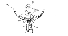
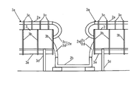
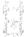
- FIG. 1 It is the schematic which shows a solar-heat collection system provided with the solar-heat collection apparatus which concerns on embodiment of this invention. It is a schematic front view which shows the heat collecting unit of the solar heat collecting device. It is a schematic side view which shows the connection part of two heat collection units of a solar heat collecting device. It is a circuit diagram for demonstrating the structure heated and supplied with an electric current through the heat-medium flow path of a solar-heat collection device.
- FIG. 1 shows a schematic configuration of a solar heat collecting system including the solar heat collecting apparatus 1 of the present embodiment.
- the solar heat collection system shown in FIG. 1 includes a plurality of solar heat collection devices 1.
- two solar heat collection devices 1 are illustrated, but actually, a large number (for example, 100 or more) of solar heat collection devices 1 are provided.
- the solar heat collected by the solar heat collection system is sent to the power generation system via a heat medium to generate power.
- These solar heat collection system and power generation system constitute a solar power generation plant.
- the solar heat collecting apparatus 1 has a substantially U-shaped heat medium flow path 2, and this heat medium flow path 2 is heated by sunlight condensed by a condenser mirror (light collecting means) 3. As a result, the temperature of the heat medium flowing through the heat medium flow path 2 rises to about 550 ° C., for example.
- a molten salt made of a mixture of sodium nitrate and potassium nitrate is used as the heating medium.
- FIG. 1 what is indicated by a small right triangle is a gradient symbol, and in accordance with this gradient symbol, the heat medium flow path 2 and an inclined pipe 5 described later are inclined with respect to the horizontal plane.
- the heat medium flow path 2 of the solar heat collecting apparatus 1 is connected to the inclined pipe 5.
- the inclined pipe 5 is configured in a loop shape, and the left end portion in FIG. 1 is higher than the right end portion. That is, the inclined pipe 5 is inclined to the lower right in FIG. 1 with respect to the horizontal plane.
- the inclined pipe 5 has two inclined pipes 5a and 5b arranged in parallel, and one inclined pipe 5a and the other inclined pipe 5b are connected to each other at both ends by pipes 5c. Yes.
- Two tanks 6 and 7 are connected to the inclined pipe 5. Each of the tanks 6 and 7 stores a heat medium.
- the tank 6 stores a heat medium before being heated by the solar heat collecting apparatus 1, and the tank 7 is a heat medium after being heated by the solar heat collecting apparatus 1. It comes to store. Therefore, hereinafter, the tank 6 is referred to as a cold side tank 6 and the tank 7 is referred to as a hot side tank 7.
- the cold side tank 6 and the inclined pipe 5a are connected by a connection pipe 10, and a heat medium is sent from the cold side tank 6 to the inclined pipe 5a by a pump (not shown) provided in the cold side tank 6. .
- the heat medium sent to the inclined pipe 5a branches at the connection portion between the connecting pipe 10 and the inclined pipe 5a, part of which flows to the right along the gradient of the inclined pipe 5a, and the remaining part of the inclined pipe 5a. It flows to the left against the gradient of 5a.
- the hot side tank 7 and the inclined pipe 5b are connected by a connection pipe 11, and the heat medium heated by the solar heat collecting device 1 is sent to the hot side tank 7 by the pressure of the pump. .
- the connection pipe 11 branches off in the middle, and a heat medium can be fed into the cold side tank 6 as necessary. For example, since the heat medium cannot be heated by the solar heat collecting device 1 at night when the sun does not come out, in that case, the heat medium is sent only to the cold side tank 6 by the switching valve provided in the branch part. The heating medium that is not heated is prevented from being fed into the hot side tank 7.
- one end of the heat medium flow path 2 of the solar heat collecting apparatus 1 is connected to the inclined pipe 5a, and the other end is connected to the inclined pipe 5b. Therefore, the heat medium flowing through the inclined pipe 5a during normal operation is a heat medium before being heated by the solar heat collecting apparatus 1, and the heat medium flowing through the inclined pipe 5b is a heat medium after being heated by the solar heat collecting apparatus 1. is there.
- the heat medium flow path 2 of the solar heat collecting apparatus 1 the heat medium flows from the end connected to the inclined pipe 5a to the end connected to the inclined pipe 5b, and the heat medium circulates through the solar heat collecting apparatus 1. It will be in the state.
- the vent portion 15 having a vent valve is provided at the highest position of the heat medium flow path 2, and by opening the vent valve of the vent portion 15, air is taken in when the heat medium is discharged. It has become.
- a heat collecting unit 3a is constituted by the condenser mirror 3 and the heat collecting tube 2a. As shown in FIGS. 2 and 3, the heat collecting unit 3 a heats the heat collecting medium 3 that collects sunlight to the heat collecting tube 2 a and the heat medium that flows inside by receiving the collected sunlight.
- the condensing mirror 3 has a substantially arc shape (concave shape) in cross section, extends to the left and right, and condenses sunlight on the straight tubular heat collecting tube 2a.
- the heat collection pipe 2a is provided with an outer pipe through which light flows and the heat medium flows inside.
- a vacuum is formed between the heat collecting tube 2a and the outer tube to form a vacuum heat insulating structure.
- the reinforcing member 3b is fixed to the back surface, which is the back side of the reflecting surface of the condensing mirror 3, and reinforces the condensing mirror 3.
- a plurality of reinforcing members 3b are provided at equal intervals along the length direction of the condenser mirror 3 and the heat collecting tube 2a.
- the reinforcing member 3b is fixed to the rotating cylinder 3e and can rotate integrally with the rotating cylinder 3e, so that the angle of the condensing mirror 3 can be changed in response to changes in the altitude of the sun.
- the tube support member 3c is fixed to the reinforcing member 3b and can rotate integrally with the rotary cylinder 3e while supporting the heat collecting tube 2a.
- the leg member 3d rotatably supports the condensing mirror 3, the heat collecting tube 2a, the reinforcing member 3b, and the tube support member 3c by rotatably supporting the rotating cylinder 3e.
- the pipe 2b is connected to the heat collecting pipe 2a via a flexible pipe (first flexible pipe) 2c and a flexible pipe (second flexible pipe) 2d, respectively.
- a flexible tube 2c connected to the heat collecting tube 2a As shown in FIG. 3, between the two heat collecting units 3a, a flexible tube 2c connected to the heat collecting tube 2a, a flexible tube 2d connected to the flexible tube 2c, and a pipe 2b connected to the flexible tube 2d.
- the flexible pipe 2d connected to the pipe 2b, the flexible pipe 2c connected to the flexible pipe 2d, and the heat collecting pipe 2a connected to the flexible pipe 2c are arranged, and the heat medium flow path 2 is constituted by these pipes. It has come to be. Since the two heat collecting units 3a are provided on the slope, the right heat collecting unit 3a is lower than the left heat collecting unit 3a.
- the two flexible pipes 2c and 2d connected in series are joined to each other in a state of being supported by a flexible support member 3f that is rotatably attached to the reinforcing member 3b or the rotating cylinder 3e.
- One flexible tube 2c is connected to the flexible tube 2d with one end connected to the heat collecting tube 2a and the other end supported by the flexible support member 3f. Therefore, the flexible tube 2c rotates integrally with the rotating cylinder 3e together with the heat collecting tube 2a and the flexible support member 3f.
- the flexible tube 2c is deformed according to expansion and contraction based on the temperature of the heat collecting tube 2a, and absorbs deformation due to expansion and contraction of the heat collecting tube 2a.
- the other flexible tube 2d is connected to the flexible tube 2c in a state where one end is supported by a flexible support member 3f that rotates integrally with the rotating cylinder 3e, and the other end is connected to a fixed pipe 2b. It deforms based on the movement of the heat collecting tube 2a corresponding to the altitude, and absorbs the displacement caused by the rotational movement of the heat collecting tube 2a.
- These flexible pipes 2c and 2d are made of a well-known metal such as stainless steel having heat resistance corresponding to the temperature of the heat medium.
- the heat collecting pipe 2a and the pipe 2b are also made of metal having heat resistance, and the flexible pipes 2c and 2d, the heat collecting pipe 2a, and the pipe 2b have conductivity.
- FIG. 1 four heat collecting units 3 a constituting one solar heat collecting device 1 are connected in series by a U-shaped heat medium flow path 2. Each heat collecting unit 3a is connected by a pipe 2b.
- the number of the heat collecting units 3a constituting the solar heat collecting apparatus 1 is not limited to four, and may be more or less than four.
- the heat collecting unit 3a is arrange
- the heat medium flow path 2 is caused to generate heat by flowing electricity directly to the heat medium flow path 2 composed of the heat collecting pipe 2a made of metal, the flexible pipes 2c and 2d, and the pipe 2b. Heating. Therefore, it is possible to heat the heat medium flow path 2 simply by connecting the power supply 30 and flowing current without attaching a heating device such as a heating wire to the outer periphery of the heat collecting pipe 2a or the flexible pipe 2c. .
- the power source 30 that supplies current to the heat medium flow path 2 serves as a heating unit.
- the heating device in the heat collecting pipe 2a does not interfere with heat reception by light collection. Further, it is not necessary to attach a heating device to the deformable flexible tubes 2c and 2d, and the heating medium flow path 2 can be heated with a very simple configuration.
- a heating method is, for example, Joule effect heating (impedance heating).
- FIG. 4 shows a circuit diagram when a current is supplied from the power supply (transformer) 30 to the heat medium flow path 2 in one solar heat collecting apparatus 1.
- a heat collecting pipe 2a, a pipe 2b, a flexible pipe 2c and a flexible pipe 2e composed of a flexible pipe 2d, a bypass cable (bypass electric circuit, power transmission cable) 2f and a closed circuit cable (described later) Wiring) 2g and power connection cable (wiring) 2h are shown by resistance symbols.
- the capacity of the power source is described as S (kVA), but a transformer having a necessary capacity may be used according to various conditions.
- the power source 30 is, for example, a transformer that transforms a single-phase 400V AC current to a voltage of about 30V, and is a floating power source in which the neutral point on the secondary coil side is not grounded.
- a power connection cable 2 h is connected from the power source 30 to the heat medium flow path 2.
- the heating medium flow path 2 is bent in a U shape as described above, so that the predetermined part on the upstream side and the predetermined part on the downstream side of the heating medium flow path 2 are arranged in parallel to each other. Yes.
- two heat collecting units 3a each including the condensing mirror 3 and the heat collecting pipe 2a are arranged on the upstream side and the downstream side of the heat medium flow path 2, respectively.
- one power source is provided for a portion (block) of one upstream heat collecting unit 3a and one downstream heat collecting unit 3a arranged side by side in the upstream heat collecting unit 3a.
- the current flows from 30. Therefore, in this embodiment, two heat collecting units are provided for each of the upstream predetermined portion and the downstream predetermined portion of the U-shaped heat medium flow path 2 of one solar heat collecting apparatus 1 arranged in parallel with each other.
- one block is formed from one adjacent heat collecting unit 3a (heat collecting pipe 2a) on the upstream side and one heat collecting unit 3a (heat collecting pipe 2a) on the downstream side. As a result, two blocks are formed in the heat medium flow path 2.
- the number of the heat collection units 3a included in one block can be arbitrarily changed according to the length and the number of the heat collection units 3a.
- the upstream side and the downstream side of the heat medium flow path 2 are arranged in parallel with each other, and for example, from the left side, the fixed pipe 2b, the flexible pipe 2e, the heat collecting pipe 2a, Various pipes are connected in series in the order of the flexible pipe 2e and the pipe 2b.
- the upper heat medium flow path 2 in the figure is the upstream side of the heat medium flow path 2
- the lower heat medium flow path 2 in the figure is the downstream side of the heat medium flow path 2.
- the heat collecting tube 2a is, for example, about 100m in total and is basically covered with an outer tube for vacuum insulation, but the divided body of the heat collecting tube 2a having about 12m of outer tubes is divided into 8 pieces. Are connected.
- a power source can be directly connected to the heat collecting tube 2a in the outer tube.
- a power connection cable 2h extending from the power source 30 to each of the two heat collecting tubes 2a in the block is connected to a connecting portion between the divided bodies of the heat collecting tubes 2a at the center of the heat collecting tube 2a.
- the upstream portion and the downstream portion of the heat medium flow path 2 are connected by a closed circuit cable 2g at a portion of the pipe 2b connected to the left and right of the heat collection pipe 2a of the heat collection unit 3a via the flexible pipe 2e. It is in the state.
- the power supply 30 is a floating power supply, whereas the closed circuit cable 2g is grounded by the ground 31.
- the power supply connection cable 2h heading upward in the figure from the power supply 30 is connected to, for example, the central portion of the heat collecting pipe 2a on the upstream side of the heat medium passage 2.
- a pair of left and right heat collecting tubes 2 a are connected to the upstream side and the downstream side of the heat medium flow path 2, respectively. This is because one heat collecting tube 2 a is divided at the central portion. It is described, and shows a state in which a power connection cable 2h is connected to the center of one heat collecting tube 2a.
- the power connection cable 2h heading upward is branched to the left and right at the portion connected to the heat collecting tube 2a, and current flows in parallel from left to right from this portion. Since the left and right parts of one block have the same structure, the left part of the block will be described here, and the description of the right part will be omitted.
- the current flowing from the power connection cable 2h extending upward flows to the left and right at the connection portion between the power connection cable 2h and the heat collecting tube 2a.
- the current flowing on the left side flows from the heat collecting tube 2a of the heat collecting unit 3a to the flexible tube 2e, flows in the order of the heat collecting tube 2a, the flexible tube 2e, and the pipe 2b, and then passes through the closed circuit cable 2g from the pipe 2b.
- the current flowing through the heat collection tube 2 a flows from the center of the heat collection tube 2 a to the lower power connection cable 2 h and reaches the power supply 30. Current also flows in the same order in the right part of the block.
- the heat collecting pipe 2a, the pipe 2b, and the flexible pipe 2e constituting the heat medium flow path 2 are different in material, cross-sectional area, length, and heat insulation structure, and when current flows in series at a constant voltage, respectively.
- the amount of heat generated based on the resistance value corresponding to the material, the cross-sectional area, and the length differs from the amount of heat released by the shape and the heat retaining structure. Therefore, when a current is simply passed in series, the amount of heat and the amount of heat released by the heat collecting pipe 2a, the pipe 2b, and the flexible pipes 2c and 2d are different, and there is a risk that a large difference in temperature occurs when the current is flowing. There is.
- the calorific value Joule heat
- H I 2 Rt.
- I the current value
- R the resistance value
- t time.
- the heat collection pipe 2a, the pipe 2b, the flexible pipe 2e, the closed circuit cable 2g, and the power connection cable 2h have a heat generation amount proportional to the respective resistance values. As shown in FIG.
- the resistance value of each resistor is Rt for the heat collecting pipe 2a, Rp for the pipe 2b, Rfp for the flexible pipe 2e, and Rc for the power connection cable 2h.
- the calorific value is calculated by multiplication. Therefore, if the actual resistance value of each member constituting the heat medium flow path 2 is known, the heat generation amount can be understood, but the temperature of each member is determined based on the heat generation amount and the heat dissipation amount. It is necessary to obtain the amount of heat generated or radiated from each member by experiment or simulation, or obtain the temperature of each member when a current is passed.
- the temperature of the pipe 2b is higher than the temperature of the heat collection pipe 2a and the flexible pipe 2e in the heat collection pipe 2a, the pipe 2b, and the flexible pipe 2e.
- the heat insulation structure is superior to the heat collection pipe 2a and the flexible pipe 2e, so that the amount of heat radiation is small and the temperature is likely to rise.
- the end of the pipe 2b connected to the flexible pipe 2e in order to reduce the value of the current flowing through the pipe 2b that is higher than the temperature of the flexible pipe 2e and the heat collecting pipe 2a.
- the bypass cable 2f is connected from the portion to the portion connected to the closed circuit cable 2g. That is, the pipe 2b and the bypass cable 2f are arranged in parallel, and the current flows separately into the pipe 2b and the bypass cable 2f, so that the value of the current flowing through the pipe 2b is reduced.
- the amount of heat generated in the pipe 2b is reduced, and the temperature of the pipe 2b can be brought closer to the heat collecting pipe 2a and the flexible pipe 2e.
- the heat collecting channel 2a occupies most of the heat medium flow path 2, and basically the voltage and current are set so that the heat collecting tube 2a is in a suitable temperature range.
- the value of the current flowing through the pipe 2b is reduced by connecting the bypass cable 2f in parallel with the pipe 2b as described above. At this time, the value of the current flowing to the bypass cable 2f side is determined by the resistance value Rp of the pipe 2b and the resistance value Rbc of the bypass cable 2f.
- the same current is used to bring the heat collecting pipe 2a, the flexible pipe 2e, and the pipe 2b to optimum temperatures.
- the value of the current flowing through the pipe 2b is set so that the temperature of the pipe 2b having the highest temperature when flowing is substantially the same as that of the heat collecting pipe 2a and the flexible pipe 2e, and the bypass cable 2f Determine the resistance value.
- the resistance value is determined by the material (the resistivity), the cross-sectional area, and the length of the bypass cable 2f, and is, for example, the low efficiency (specific resistance) multiplied by the length and divided by the cross-sectional area.
- the resistance value necessary for the bypass cable 2f is estimated, and the resistance value is set by the length of the bypass cable 2f, for example. It is preferable that the length of the bypass cable 2f is not shorter than the length of the bypassed portion of the pipe 2b, and the corresponding cross-sectional area of the conductive wire to be the above-described bypass cable 2f (the conductive wire multiplied by the cross-sectional area of one conductive wire) It is necessary to determine the number of Since the bypass cable 2f is longer than the bypassed portion of the pipe 2b, for example, the longer portion of the bypass cable 2f than the bypassed portion of the pipe 2b is stored in a case, for example. Is preferred.
- bypass cable 2f when the bypass cable 2f is bundled in the case, it is not in a state of being wound around a cable reel (coiled), but for example, in a long case of 1 m or longer, the longer diameter side becomes longer along the inner wall of the case. Thus, it is preferable that the winding is performed with a small number of windings.
- the value of the electric current which flows into the piping 2b can be changed so that it may differ from the heat collecting pipe 2a and the flexible pipe 2e. it can.
- a bypass cable 2f is arranged in parallel to the flexible tube 2e so that the flexible tube 2e The amount of current flowing is less than the amount of current flowing through the heat collection tube 2a , or conversely, a bypass cable 2f is arranged in parallel on the heat collection tube 2a side so that the amount of current flowing through the heat collection tube 2a is less than the amount of current flowing through the flexible tube 2e. May be.
- a solar heat collecting apparatus 1 at the time of start-up, when the molten salt as the heat medium is introduced into the heat medium flow path 2, or when the molten salt is discharged from the heat medium flow path 2 at the time of maintenance, maintenance is performed.
- the heat medium flow path 2 can be heated to prevent the molten salt from solidifying.
- the heat collecting tube 2a includes the heat collecting tube 2a as a structure that does not block the concentrated solar heat or a structure that can heat the heat collecting tube 2a even if there is a vacuum heat insulating structure on the outer periphery of the heat collecting tube 2a. Since a structure in which a current is directly passed through the heat medium passage 2 is employed, the heat collecting tube 2a can be heated with an extremely simple structure.
- a heating wire that follows the deformation of the flexible pipe 2e. It is possible to heat the flexible tube 2e by flowing an electric current without using the, so that the flexible tube 2e can be heated with a simple structure.
- the heat collecting pipe 2a, the flexible pipe 2e, and the pipe 2b which have different resistance values and heat dissipation amounts due to differences in the heat insulation structure, are connected in series to the heating medium flow path 2 that heats by supplying electricity, respectively. Based on the fact that the same current flows, a large temperature difference may occur between the tubes during heating. For example, the temperature is parallel to the pipe 2b where the temperature is higher than that of the heat collecting pipe 2a or the flexible pipe 2e.
- the bypass cable 2f it is possible to reduce the amount of current flowing through the pipe 2b from the amount of current flowing through the heat collecting tube 2a and the flexible tube 2e while being arranged in series.
- a current is passed in series based on the presence or absence of the bypass cable 2f and the resistance value of the bypass cable 2f.
- the temperature of each member can be set individually, and the temperature of each member can be set to be close to each other.
- the portions of the heat medium flow path 2 including the heat collecting pipes 2a that are arranged substantially in parallel with each other are arranged substantially in parallel with each other with a closed circuit cable (power transmission cable) 2g and a power connection cable (power transmission cable). 2h is connected to 2h to form a closed circuit for supplying current to the heat medium flow path 2. If the distance between the heat collecting tubes 2a arranged in parallel to each other is short, a power transmission cable for forming the closed circuit Can be shortened. Thereby, the installation work of the power transmission cable can be facilitated, and the cost and power transmission loss of the power transmission cable can be reduced.
- the flexible tube 2e is mainly deformed according to expansion and contraction based on the temperature of the heat collecting tube 2a, and the flexible tube 2d is connected to the flexible tube 2c and mainly deformed according to the movement of the heat collecting tube 2a. It has become. That is, the flexible tube 2e is divided into a portion that deforms corresponding to the expansion and contraction of the heat collecting tube 2a and a portion that deforms corresponding to the movement of the heat collecting tube 2a. It is possible to prevent a problem from being easily caused by the flexible tube 2e hitting a surrounding member in a state where electricity is passed and the portion where 2e freely deforms becomes long. In addition, it is preferable that the part to which the first flexible tube 2c and the second flexible tube 2d are joined is in a state of moving integrally with the heat collecting tube 2a.
- the bypass cable 2f as a bypass circuit is composed of a power transmission cable, and is provided with an insulating layer and a protective cover around the conductor, and can be easily used outdoors, has a low resistance value, and has a long length. Since it can be set freely, it is easy to set the resistance value finely. Moreover, the power transmission cable is relatively easy to bend, and even if it is long, it can be disposed relatively compactly in accordance with the installation location.
- the power supply 30 is provided in each of the two blocks including the two heat collecting units 3a so that a current flows through the heat medium flow path 2. It has a structure.
- the two heat collecting units 3a of one block are divided into two parts so that current flows in parallel.
- a power source 30 may be arranged for each heat collecting unit 3a to allow current to flow, or the two heat collecting units 3a in one block are divided into two parts and not connected in parallel to the power source 30. You may connect the power supply 30 so that it may be in series with the heat-medium flow path 2 of each of the two heat collection units 3a.
Landscapes
- Engineering & Computer Science (AREA)
- Chemical & Material Sciences (AREA)
- Combustion & Propulsion (AREA)
- Sustainable Development (AREA)
- Sustainable Energy (AREA)
- Life Sciences & Earth Sciences (AREA)
- Mechanical Engineering (AREA)
- General Engineering & Computer Science (AREA)
- Thermal Sciences (AREA)
- Physics & Mathematics (AREA)
- Pipe Accessories (AREA)
- Rigid Pipes And Flexible Pipes (AREA)
- Photovoltaic Devices (AREA)
Abstract
L'invention fournit un dispositif de captation de chaleur solaire permettant de chauffer efficacement un trajet d'écoulement de fluide chauffant constitué de tubes de différentes sortes. Ce dispositif de captation de chaleur solaire (1) est équipé du trajet d'écoulement de fluide chauffant (2) dans lequel s'écoule un fluide chauffant en une position de captation lumineuse d'un miroir de captation lumineuse (3) captant une chaleur solaire. Le trajet d'écoulement de fluide chauffant (2) est configuré par connexion en série de différentes sortes de tubes conducteurs contenant un tube de captation de chaleur (2a) disposé sur la position de captation lumineuse du miroir de captation lumineuse (3). L'objet de l'invention est également équipé d'un moyen de chauffage (30) tel qu'une électricité s'écoule en série dans le tube de captation de chaleur (2a), dans un tube flexible (2e) et dans un conduit (2b) connectés en série. Un câble de dérivation (2f) dans lequel s'écoule en parallèle le courant vis-à-vis du conduit (2b), est agencé au niveau de ce dernier.
Priority Applications (4)
| Application Number | Priority Date | Filing Date | Title |
|---|---|---|---|
| EP15897179.6A EP3318814A4 (fr) | 2015-07-02 | 2015-07-02 | Dispositif de captation de chaleur solaire |
| CN201580081312.2A CN107923657A (zh) | 2015-07-02 | 2015-07-02 | 太阳热收集装置 |
| PCT/JP2015/069088 WO2017002252A1 (fr) | 2015-07-02 | 2015-07-02 | Dispositif de captation de chaleur solaire |
| JP2017525764A JP6543707B2 (ja) | 2015-07-02 | 2015-07-02 | 太陽熱収集装置 |
Applications Claiming Priority (1)
| Application Number | Priority Date | Filing Date | Title |
|---|---|---|---|
| PCT/JP2015/069088 WO2017002252A1 (fr) | 2015-07-02 | 2015-07-02 | Dispositif de captation de chaleur solaire |
Publications (1)
| Publication Number | Publication Date |
|---|---|
| WO2017002252A1 true WO2017002252A1 (fr) | 2017-01-05 |
Family
ID=57608295
Family Applications (1)
| Application Number | Title | Priority Date | Filing Date |
|---|---|---|---|
| PCT/JP2015/069088 Ceased WO2017002252A1 (fr) | 2015-07-02 | 2015-07-02 | Dispositif de captation de chaleur solaire |
Country Status (4)
| Country | Link |
|---|---|
| EP (1) | EP3318814A4 (fr) |
| JP (1) | JP6543707B2 (fr) |
| CN (1) | CN107923657A (fr) |
| WO (1) | WO2017002252A1 (fr) |
Cited By (2)
| Publication number | Priority date | Publication date | Assignee | Title |
|---|---|---|---|---|
| IT201700088140A1 (it) * | 2017-08-01 | 2019-02-01 | Astroflex S P A | Conduttura flessibile per il collegamento del tubo ricevitore di un concentratore solare orientabile a tubazioni fisse, e concentratore solare impiegante tale conduttura flessibile |
| WO2024217628A1 (fr) | 2023-04-18 | 2024-10-24 | Frenell Ip Gmbh | Centrale héliothermique comportant un système de canalisations chauffé en continu |
Citations (4)
| Publication number | Priority date | Publication date | Assignee | Title |
|---|---|---|---|---|
| US20100175689A1 (en) * | 2009-01-13 | 2010-07-15 | Hamilton Sundstrand Corporation | Catalyzed hot gas heating system for pipes |
| JP2014159892A (ja) * | 2013-02-19 | 2014-09-04 | Toshiba Corp | 太陽熱集熱装置、および、太陽熱発電システム |
| JP2014523997A (ja) * | 2011-05-19 | 2014-09-18 | ビーエーエスエフ ソシエタス・ヨーロピア | 溶融塩を送る管路 |
| JP2014531552A (ja) * | 2011-09-06 | 2014-11-27 | ビーエーエスエフ ソシエタス・ヨーロピアBasf Se | パイプラインシステム及びパイプラインシステムをドレンする方法 |
Family Cites Families (5)
| Publication number | Priority date | Publication date | Assignee | Title |
|---|---|---|---|---|
| JP2007128751A (ja) * | 2005-11-04 | 2007-05-24 | Tokuden Co Ltd | 流体加熱装置及びその装置を使用した熱媒体通流ローラ装置 |
| DE102008037711A1 (de) * | 2008-08-14 | 2010-02-18 | Senior Berghöfer GmbH | Anschlusssystem für ein um eine Drehachse schwenkbares Leitungsrohr einer solarthermischen Anlage |
| ES2500865B1 (es) * | 2011-10-20 | 2015-07-20 | Abengoa Solar Llc | Sistema de calentamiento de un fluido de transferencia de calor para un concentrador solar cilindro-parabólico |
| US9347596B2 (en) * | 2013-02-27 | 2016-05-24 | Basf Se | Apparatus for heating a pipeline |
| CN203731722U (zh) * | 2013-12-30 | 2014-07-23 | 北京工业大学 | 一种槽式真空集热管直流大电流熔盐解冻预热装置 |
-
2015
- 2015-07-02 WO PCT/JP2015/069088 patent/WO2017002252A1/fr not_active Ceased
- 2015-07-02 JP JP2017525764A patent/JP6543707B2/ja not_active Expired - Fee Related
- 2015-07-02 CN CN201580081312.2A patent/CN107923657A/zh active Pending
- 2015-07-02 EP EP15897179.6A patent/EP3318814A4/fr not_active Withdrawn
Patent Citations (4)
| Publication number | Priority date | Publication date | Assignee | Title |
|---|---|---|---|---|
| US20100175689A1 (en) * | 2009-01-13 | 2010-07-15 | Hamilton Sundstrand Corporation | Catalyzed hot gas heating system for pipes |
| JP2014523997A (ja) * | 2011-05-19 | 2014-09-18 | ビーエーエスエフ ソシエタス・ヨーロピア | 溶融塩を送る管路 |
| JP2014531552A (ja) * | 2011-09-06 | 2014-11-27 | ビーエーエスエフ ソシエタス・ヨーロピアBasf Se | パイプラインシステム及びパイプラインシステムをドレンする方法 |
| JP2014159892A (ja) * | 2013-02-19 | 2014-09-04 | Toshiba Corp | 太陽熱集熱装置、および、太陽熱発電システム |
Non-Patent Citations (1)
| Title |
|---|
| See also references of EP3318814A4 * |
Cited By (3)
| Publication number | Priority date | Publication date | Assignee | Title |
|---|---|---|---|---|
| IT201700088140A1 (it) * | 2017-08-01 | 2019-02-01 | Astroflex S P A | Conduttura flessibile per il collegamento del tubo ricevitore di un concentratore solare orientabile a tubazioni fisse, e concentratore solare impiegante tale conduttura flessibile |
| WO2024217628A1 (fr) | 2023-04-18 | 2024-10-24 | Frenell Ip Gmbh | Centrale héliothermique comportant un système de canalisations chauffé en continu |
| DE102023109750A1 (de) * | 2023-04-18 | 2024-10-24 | Frenell Ip Gmbh | Solarthermisches kraftwerk mit lückenlos beheiztem rohrleitungssystem |
Also Published As
| Publication number | Publication date |
|---|---|
| EP3318814A4 (fr) | 2019-01-09 |
| CN107923657A (zh) | 2018-04-17 |
| JPWO2017002252A1 (ja) | 2018-03-29 |
| EP3318814A1 (fr) | 2018-05-09 |
| JP6543707B2 (ja) | 2019-07-10 |
Similar Documents
| Publication | Publication Date | Title |
|---|---|---|
| JP5657576B2 (ja) | 太陽熱集熱器及び当該太陽熱集熱器を含む電気エネルギー生成設備 | |
| US7296410B2 (en) | Solar power system and method for power generation | |
| US7055519B2 (en) | Solar collector and method | |
| AU2012258271B2 (en) | Pipeline for conveying a salt melt | |
| WO2009002168A1 (fr) | Dispositif pour collecter de l'énergie solaire | |
| US20150107246A1 (en) | System and method for heat storage in solar thermal power plants | |
| JP6543707B2 (ja) | 太陽熱収集装置 | |
| ES3033483T3 (en) | Energy storage device and method of heating a heat transfer fluid | |
| JP5662098B2 (ja) | 冷温水製造装置 | |
| JP6543711B2 (ja) | 太陽熱収集装置 | |
| US20170045264A1 (en) | Joints and Joining Methods for the Heat Transfer Fluid Circuit of Trough-Type Solar Collector Systems | |
| JP6543710B2 (ja) | 加熱装置 | |
| JP6543709B2 (ja) | 加熱システム | |
| WO2017002262A1 (fr) | Dispositif de chauffage | |
| Machado et al. | Experimental Investigation on the Influence of the Diameter on Thermosyphons for Application in a Hybrid Photovoltaic/Thermal System | |
| CN107709891B (zh) | 太阳能热收集装置的接地构造、太阳能热收集装置和太阳能热发电系统 |
Legal Events
| Date | Code | Title | Description |
|---|---|---|---|
| 121 | Ep: the epo has been informed by wipo that ep was designated in this application |
Ref document number: 15897179 Country of ref document: EP Kind code of ref document: A1 |
|
| ENP | Entry into the national phase |
Ref document number: 2017525764 Country of ref document: JP Kind code of ref document: A |
|
| WWE | Wipo information: entry into national phase |
Ref document number: 2015897179 Country of ref document: EP |
|
| NENP | Non-entry into the national phase |
Ref country code: DE |