WO2017002282A1 - Procédé et dispositif de communication sans fil - Google Patents
Procédé et dispositif de communication sans fil Download PDFInfo
- Publication number
- WO2017002282A1 WO2017002282A1 PCT/JP2016/001367 JP2016001367W WO2017002282A1 WO 2017002282 A1 WO2017002282 A1 WO 2017002282A1 JP 2016001367 W JP2016001367 W JP 2016001367W WO 2017002282 A1 WO2017002282 A1 WO 2017002282A1
- Authority
- WO
- WIPO (PCT)
- Prior art keywords
- frequency domain
- value
- resource
- resource block
- block set
- Prior art date
- Legal status (The legal status is an assumption and is not a legal conclusion. Google has not performed a legal analysis and makes no representation as to the accuracy of the status listed.)
- Ceased
Links
Images





Classifications
-
- H—ELECTRICITY
- H04—ELECTRIC COMMUNICATION TECHNIQUE
- H04W—WIRELESS COMMUNICATION NETWORKS
- H04W16/00—Network planning, e.g. coverage or traffic planning tools; Network deployment, e.g. resource partitioning or cells structures
- H04W16/14—Spectrum sharing arrangements between different networks
-
- H—ELECTRICITY
- H04—ELECTRIC COMMUNICATION TECHNIQUE
- H04L—TRANSMISSION OF DIGITAL INFORMATION, e.g. TELEGRAPHIC COMMUNICATION
- H04L5/00—Arrangements affording multiple use of the transmission path
- H04L5/0001—Arrangements for dividing the transmission path
- H04L5/0028—Variable division
-
- H—ELECTRICITY
- H04—ELECTRIC COMMUNICATION TECHNIQUE
- H04L—TRANSMISSION OF DIGITAL INFORMATION, e.g. TELEGRAPHIC COMMUNICATION
- H04L5/00—Arrangements affording multiple use of the transmission path
- H04L5/003—Arrangements for allocating sub-channels of the transmission path
- H04L5/0048—Allocation of pilot signals, i.e. of signals known to the receiver
-
- H—ELECTRICITY
- H04—ELECTRIC COMMUNICATION TECHNIQUE
- H04W—WIRELESS COMMUNICATION NETWORKS
- H04W16/00—Network planning, e.g. coverage or traffic planning tools; Network deployment, e.g. resource partitioning or cells structures
- H04W16/02—Resource partitioning among network components, e.g. reuse partitioning
- H04W16/10—Dynamic resource partitioning
-
- H—ELECTRICITY
- H04—ELECTRIC COMMUNICATION TECHNIQUE
- H04W—WIRELESS COMMUNICATION NETWORKS
- H04W8/00—Network data management
- H04W8/005—Discovery of network devices, e.g. terminals
-
- H—ELECTRICITY
- H04—ELECTRIC COMMUNICATION TECHNIQUE
- H04L—TRANSMISSION OF DIGITAL INFORMATION, e.g. TELEGRAPHIC COMMUNICATION
- H04L5/00—Arrangements affording multiple use of the transmission path
- H04L5/0091—Signalling for the administration of the divided path, e.g. signalling of configuration information
- H04L5/0092—Indication of how the channel is divided
-
- H—ELECTRICITY
- H04—ELECTRIC COMMUNICATION TECHNIQUE
- H04W—WIRELESS COMMUNICATION NETWORKS
- H04W92/00—Interfaces specially adapted for wireless communication networks
- H04W92/16—Interfaces between hierarchically similar devices
- H04W92/18—Interfaces between hierarchically similar devices between terminal devices
Definitions
- This disclosure relates to direct communication between devices (device-to-device (D2D) communication), and more particularly to transmission of a discovery signal.
- D2D device-to-device
- D2D communication A form in which a wireless terminal communicates directly with another wireless terminal without going through an infrastructure network such as a base station is called device-to-device (D2D) communication.
- the D2D communication includes at least one of direct communication (Direct Communication) and direct discovery (Direct Discovery).
- a plurality of wireless terminals that support D2D communication form a D2D communication group autonomously or according to a network instruction, and communicate with other wireless terminals in the D2D communication group.
- Proximity-based services defined in 3GPP Release 12 is an example of D2D communication (see, for example, Non-Patent Document 1).
- ProSe Direct Discovery is a wireless terminal that can execute ProSe (ProSe-enabled User Equipment (UE)) and other ProSe-enabled UEs. -UTRA) It is performed by the discovery procedure using only the technology (technology).
- ProSe direct discovery may be performed by three or more ProSe-enabled UEs.
- ProSe direct communication enables the establishment of a communication path between two or more ProSe-enabled UEs existing in the direct communication range after the ProSe direct discovery procedure.
- ProSe direct communication enables ProSe-enabled UEs to communicate directly with other ProSe-enabled UEs without going through the public land mobile communication network (Public Land Mobile Mobile Network (PLMN)) including the base station (eNodeB). Allows to communicate.
- ProSe direct communication may be performed using the same wireless communication technology (E-UTRA technology) as that used to access the base station (eNodeB), or wireless local wireless network (WLAN) wireless technology (ie IEEE 802.11 (radio technology) may be used.
- E-UTRA technology wireless communication technology
- WLAN wireless local wireless network
- IEEE 802.11 radio technology
- a wireless link between wireless terminals used for direct communication or direct discovery is referred to as a side link (see, for example, Section 14 of Non-Patent Document 2).
- Sidelink transmission uses the same frame structure as the Long Term Evolution (LTE) frame structure defined for uplink and downlink, and uses a subset of uplink resources in frequency and time domain.
- the radio terminal (UE) performs side link transmission using single carrier frequency division multiplexing (Single-Carrier-FDMA (Frequency-Division-Multiple Access), SC-FDMA) similar to the uplink.
- Single-Carrier-FDMA Frequency-Division-Multiple Access
- radio resources for side link transmission are allocated to UEs by a radio access network (e.g., Evolved Universal Terrestrial Radio Access Network (E-UTRAN)).
- E-UTRAN Evolved Universal Terrestrial Radio Access Network
- a UE that is permitted to perform side link communication by ProSe function performs ProSe direct discovery or ProSe direct communication using radio resources allocated by radio access network nodes (e.g., eNodeB (eNB)).
- eNodeB eNodeB
- autonomous resource selection and scheduled resource allocation are called “sidelink discovery Type 1" and “sidelink discovery Type 2", respectively.
- ProSe direct discovery autonomous resource selection (sidelink discovery Type 1) allows UEs that want to send discovery signals (ie, Physical Sidelink Shared Channel (PSDCH)) autonomously to use the resource pool from the resource pool. select.
- discovery signals ie, Physical Sidelink Shared Channel (PSDCH)
- ProSe direct discovery scheduled resource allocation (sidelink discovery Type 2)
- the UE requests resource allocation for announcement from the eNodeB via RRC signaling.
- the eNodeB allocates an announcement resource from the resource pool to the UE.
- eNodeB supports providing resources for monitoring ProSe direct discovery in System Information Block (SIB 19), but does not provide resources for announcements.
- SIB 19 System Information Block
- a resource pool for ProSe direct discovery is called a discovery resource pool, and is set in the UE by the eNB by broadcast (SIB 19) or dedicated signaling (RRC signaling).
- the discovery resource pool is composed of L PSDCH subframes and M PSDCH_RP RB frequency domain resource blocks within a discovery period.
- the discovery period is also referred to as a PSDCH period.
- the discovery resource pool is composed of a subframe pool and a resource block pool.
- eNB specifies the length of the discovery period (P), the number of repetitions of the subframe bitmap within the discovery period (N R ), and the subframe bitmap and its length in order to identify the subframe pool Specify (N B ).
- the length of discovery period (P) is 32, 64, 128, 256, 512, or 1024 radio frames.
- a 3GPP Release (12 (LTE-advanced) radio frame has a length of 10 milliseconds and is composed of 10 subframes. The length of one subframe is 1 millisecond. Therefore, the length (P) of the discovery period is 320, 640, 1280, 2560, 5120, or 10240 subframes.
- the length (N B ) of the subframe bitmap is 4, 8, 12, 16, 30, 40 or 42 bits.
- the subframe bitmap indicates that the subframe corresponding to the bit set to “0” is not used for discovery, and the subframe corresponding to the bit set to “1” can be used for discovery.
- the maximum number of subframe bitmap repetitions (N R ) within the discovery period depends on the duplex mode, frequency division duplex (FDD) or time division duplex (TDD), and UL / DL for TDD Depends on configuration. Specifically, the maximum number of repetitions (N R ) is 5 for FDD and TDD UL / DL configuration 0, 13 for TDD UL / DL configuration 1, and TDD UL / DL. Value 25 for configuration 2, value 17 for TDD UL / DL configuration 3, value 25 for TDD UL / DL configuration 4, and value 50 for TDD UL / DL configuration 5. In the case of TDD UL / DL configuration 6, the value is 7.
- the number of subframes (L PSDCH ) included in the discovery resource pool corresponding to one discovery period is multiplied by the number of repetitions (N R ) by the number specified by the value 1 in the subframe bitmap. It is obtained with.
- the sub-frame bitmap length of (N B) is 8 bits
- number of repetitions (N R) is 4.
- 4 bits out of 8 bits in one subframe bitmap are set to use (value “1”) (hatched subframe in FIG. 1). Therefore, the number of subframes (L PSDCH ) included in the discovery resource pool is 16.
- the eNB specifies the start (start) Physical ⁇ Resource Block (PRB) index (S1), the end (end) PRB index (S2), and the number of PRBs (M) to identify the resource block pool To do.
- FIG. 2 is a diagram illustrating an example of a discovery resource pool within one discovery period.
- the number of subframes (L PSDCH ) included in the discovery resource pool is 16.
- the subframes included in the discovery resource pool (ie, subframe pool) can be expressed as follows:
- the number of resource blocks (PRB) (M RB PSDCH_RP ) included in the discovery resource pool is 16.
- Resource blocks included in a discovery resource pool can be represented as follows:
- FIG. 2 several drawings similar to FIG. 2 are used to represent discovery resource pools within one discovery period.
- a plurality of subframes included in one discovery resource pool may not be temporally continuous, and a plurality of resources included in one discovery resource pool. It should be noted that the block contains two clusters.
- radio resource allocation for transmitting a discovery signal (PSDCH) defined in 3GPP Release 12 will be described below.
- the details of the radio resource allocation are described in detail in Section 14.3 of Non-Patent Document 2.
- radio resource allocation for discovery signal (PSDCH) transmission is defined in two different systems, namely, sidelink discovery Type 1 and Type 2.
- Sidelink discovery Type 1 radio resources are allocated without depending on the UE (on a non-UE specific basis).
- Sidelink discovery Type 2 radio resources are allocated according to UE (on a UE specific basis). Note that, for Type 2, two types, Type 2 A and Type 2 B, have been studied, but in Current Release 12, only Type 2 B is defined.
- Type 2B the eNB allocates radio resources to the UE semi-persistent for discovery signal (PSDCH) transmission.
- PSDCH discovery signal
- Type 2 A the eNB dynamically allocates radio resources for discovery signal (PSDCH) transmission to the UE for each discovery period (PSDCH period).
- Sidelink discovery Type 1 resource allocation will be described.
- the UE autonomously selects a resource value n PSDCH and determines subframes and resource blocks for PSDCH transmission as follows.
- n is given by discoveryNumRetx which is an upper layer parameter.
- the parameter discoveryNumRetx is set to the UE by the eNB using dedicated signaling (RRC Connection Reconfiguration), for example.
- n PSDCH The range of resource values n PSDCH that can be selected by the UE is an integer greater than or equal to zero and less than or equal to (N t * N f ⁇ 1), where N t and N f are defined as
- the j-th transmission for a discovery signal (ie, transport block on PSDCH) within the discovery period is L PSDCH subframes l 0 PSDCH , l 1 PSDCH ,... In the discovery resource pool.
- ⁇ of the l L_PSDCH-1 PSDCH Two consecutive resource blocks of the subframe that occur in Is used. here, It is.
- n PSDCH 4
- the first, second, third, and fourth subframes l 0 PSDCH , l 1 PSDCH , l 2 PSDCH , and l in the discovery resource pool 3 PSDCH transmission is performed 4 times in PSDCH.
- 3GPP TS 23.303 V12.4.0 (2015-03), “3rd Generation Partnership Project; Technical Specification Group Services Services and System Aspects Proximity-based Services (ProSe); Stage 2 Release (Release 12), March 2015 3GPP TS 36.213 V12.5.0 (2015-03), “3rd Generation Partnership Project; Technical Specification Group Radio Access Network; Evolved Universal Terrestrial Radio Access (E-UTRA); Physical layer procedures (Release 12), 2015
- N SLD TX PSDCH transmissions within the discovery period occur in the exact same set of subframes.
- n PSDCH is 0,4,8,12,16,24, and 28
- the subframe l 0 PSDCH, l 1 PSDCH, l 2 PSDCH, and l 3 4 times in PSDCH PSDCH transmission is performed.
- the resource block used in the j-th PSDCH transmission is a constant value in the frequency domain from the resource block used in the (j-1) -th transmission, that is, Is only cyclically shifted.
- the value of the frequency domain shift from the resource block used in the (j ⁇ 1) th PSDCH transmission of the resource block used in the jth transmission is the resource value n PSDCH selected by the UE.
- the resource block used in the (j ⁇ 1) -th PSDCH transmission is a constant value in the frequency domain from the resource block used in the (j-1) -th transmission, that is, Is only cyclically shifted.
- the value of the frequency domain shift from the resource block used in the (j ⁇ 1) th PSDCH transmission of the resource block used in the jth transmission is the resource value n PSDCH selected by the UE.
- the resource block used in the (j ⁇ 1) -th PSDCH transmission is the resource value n PSDCH selected by the UE.
- the monitoring UE 401 while the monitoring UE 401 is attempting to monitor the discovery signal (desired signal) from the announcing UE 402, another announcing UE 403 is in the vicinity of the monitoring UE 401 and the discovery signal (undesired signal).
- the two announcing UEs 402 and 403 are completely the same.
- the monitoring UE 401 may deteriorate the reception quality of the discovery signal (desired signal) from the announcement UE 402 due to in-band interference.
- One of the objects to be achieved by the embodiments disclosed in this specification is to contribute to suppressing a decrease in reception quality of a discovery signal due to interference caused by IBE when direct discovery of D2D communication is performed.
- An apparatus, a method, and a program are provided.
- a wireless communication method in a wireless terminal is selected spontaneously from a resource pool composed of L subframes and M frequency domain resource blocks within a discovery period.
- N TX subframes used for transmission of the N TX times discovery signals within the discovery period N includes selecting resource sets for the TX set.
- each set of N TX set of resource blocks are used for transmission of each of the discovery signal at one of the N TX subframes.
- the (j ⁇ 1) th of the first resource block set used for transmitting the discovery signal of the jth time (j is an integer of 2 or more) within the discovery period.
- the value of the frequency domain shift from the second resource block set used for the second transmission is the first value n1 and the frequency domain position in the resource pool of the second resource block set. Depends on at least one.
- a wireless terminal includes at least one wireless transceiver and at least one processor.
- the at least one processor is configured to perform cellular communication with a cellular network and device-to-device communication with other wireless terminals using the at least one wireless transceiver.
- the at least one processor further includes a first resource value spontaneously selected by the wireless terminal from a resource pool including L subframes and M frequency domain resource blocks within a discovery period. based on the first value n1 of parameters received from the value n1 or base station, the N TX subframes and N TX set of resource blocks used for transmission of the N TX times discovery signals within a discovery period Configured to select.
- each set of N TX set of resource blocks are used for transmission of each of the discovery signal at one of the N TX subframes.
- the (j ⁇ 1) th of the first resource block set used for transmitting the discovery signal of the jth time (j is an integer of 2 or more) within the discovery period.
- the value of the frequency domain shift from the second resource block set used for the second transmission is the first value n1 and the frequency domain position in the resource pool of the second resource block set.
- the program includes a group of instructions (software code) for causing the computer to perform the method according to the first aspect when read by the computer.
- FIG. 5 is a flowchart illustrating an example of an operation of the wireless terminal according to the first embodiment.
- LTE-Advanced ProSe specified in 3GPP Release 12
- these embodiments are not limited to LTE-Advanced and its improvements, and may be applied to D2D communication in other mobile communication networks or systems.
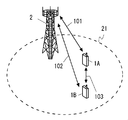
- FIG. 5 shows configuration examples of wireless communication systems according to some embodiments including the present embodiment.
- Each of the UEs 1A and 1B has at least one radio transceiver and performs cellular communication (101 or 102) with the base station 2 and D2D communication on the direct interface (eg, PC5 interface or side link) 103 between terminals. Is configured to do.
- the D2D communication includes at least direct discovery (eg, ProSe Direct Discovery) and may further include direct communication (ProSe Direct Communication).
- the eNB 2 manages the cell 21 and can perform cellular communication (101 and 102) with each of the plurality of UEs 1 using cellular communication technology (eg, Evolved Universal Terrestrial Radio Access (E-UTRA) technology).
- E-UTRA Evolved Universal Terrestrial Radio Access
- UE1A may be located in one cell of two adjacent cells managed by different eNB2, and UE1B may be located in the other cell.
- UE1A and UE1B may be located outside the coverage by one or a plurality of eNBs 2.
- N TX SLD discovery signals in the discovery period from the discovery resource pool consisting of L PSDCH subframes and M PSDCH_RP RB frequency domain resource blocks in the discovery period (PSDCH period).
- N TX SLD subframes and N TX SLD set resource blocks are selected for transmission.
- Each set of selected N TX SLD set of resource blocks are used for transmission of each discovery signal at one of the N TX SLD subframes selected.
- each set of resource blocks of the N TX SLD set is composed of two consecutive resource blocks.
- UE1 selects N TX SLD subframes and N TX SLD set resource blocks based on the resource value n PSDCH voluntarily selected by UE1. May be.
- UE1 includes one or more parameters (eg, N PSDCH (1) , N PSDCH (2) , and N PSDCH (3) ) from eNB2. receive PSDCH resource settings (configuration), according to at least one of these one or more parameters may be selected N TX SLD subframes and N TX SLD set of resource blocks.
- FIG. 6 is a flowchart illustrating an example of operation of UE 1 (process 600) when selecting a radio resource for direct discovery.
- FIG. 6 shows sidelink discovery Type 1 (autonomous resource selection).
- UE1 autonomously selects a resource value n PSDCH .
- UE1 based on the selected resource value n PSDCH, N SLD TX subframes for transmission of N SLD TX times discovery signals within the discovery period (PSDCH period) (PSDCH) and Select resource block for N TX SLD set.
- PSDCH period discovery period
- Select resource block for N TX SLD set is used to transmit a discovery signal in one of the N TX SLD subframes.
- the first resource block set of the first resource block set used for transmission of the jth discovery signal (j is an integer of 2 or more) by UE1 within the discovery period.
- the value of the frequency domain shift from the second resource block set used for the (j-1) th transmission is determined as follows. That is, the value of the frequency domain shift includes (a) the value of the resource value n PSDCH selected by UE1, and (b) the second resource block set used for the (j ⁇ 1) th transmission. Depending on at least one of the frequency domain positions in the discovery resource pool.
- the first resource block set used for the jth (j is an integer greater than or equal to 2) PSDCH transmission by UE1 and the (j-1) th PSDCH transmission.
- the value of the frequency domain shift between the second resource block set depends on whether the resource value n PSDCH selected by the UE 1 is the first value or the second value. Different.
- the first resource block set used for the jth (j is an integer greater than or equal to 2) PSDCH transmission by UE1 and the (j-1) th PSDCH transmission
- the value of the frequency domain shift between the second resource block set is whether the frequency domain position in the discovery resource pool of the second resource block set is the first position or the second position. Depends on what you do.
- frequency domain position in the discovery resource pool is used in the discovery resource pool (resource block pool) of the target resource block or resource block set (ie, two consecutive resource blocks). Means a logical order in For example, “frequency domain position in the discovery resource pool” is a logical serial number 0, 1, ..., assigned to M RB PSDCH_RP / 2 resource block sets included in the discovery resource pool. It may be represented by (M RB PSDCH_RP / 2-1 ).
- the present embodiment is used in the (j-1) th PSDCH transmission of the resource block set used in the jth (1 ⁇ j) PSDCH transmission by UE1.
- the value of the frequency domain shift from the resource block set is either the value of the resource value n PSDCH selected by the UE 1 and the resource block set used in the (j ⁇ 1) -th PSDCH transmission or Depends on both.
- This allows two UEs 1 that transmit discovery signals in the same N TX SLD subframes based on different resource values n PSDCH values to use different frequency domain shift values. Therefore, it can be avoided that these two UEs 1 perform all N TX SLD PSDCH transmissions in the same subframe group using two resource block sets having the same adjacency relationship.
- N TX SLD discovery signal PSDCH
- any other transmission may be separated by two resource blocks separated in the frequency domain. This is to use the set.
- the subframe selection rule or algorithm at block 602 indicates that the (j ⁇ 1) th of the first resource block set used in the jth (1 ⁇ j) PSDCH transmission by UE1.
- the value of the frequency domain shift from the second resource block set used in the PSDCH transmission of the second resource block set is a serial number (ie, 0, 1, ..., ( It may be determined depending on the value of M RB PSDCH_RP / 2-1 )).
- mapping between resource value n PSDCH and radio resources will be described.
- the frequency domain shift value from the block set is an odd number (ie, 0, 1, ..., (M RB PSDCH_RP / 2-1 )) representing the frequency domain position of the second resource block set Depending on whether it is or even.
- n PSDCH the range of resource value n PSDCH that UE1 can select is an integer that is greater than or equal to zero and less than or equal to (N t * N f ⁇ 1), where N t and N f are as follows: Defined:
- N TX SLD subframes may be the same as in 3GPP Release 12 sidelink discovery Type 1. That is, when UE1 is set to transmit PSDCH in the i-th PSDCH period, the transmission of the j-th transport block (j is 1 or more and N TX SLD or less) on the PSDCH is a discovery resource.
- the L PSDCH subframes l 0 , l 1 ,..., L L_PSDCH-1 in the pool Two consecutive resource blocks of the subframe that occur in Is used. here, It is.
- a j-1 represents the frequency domain position of the resource block set (ie, two consecutive resource blocks) for the (j-1) th PSDCH transmission.
- a j represents the frequency domain position of the resource block set (ie, two consecutive resource blocks) for the j-th PSDCH transmission.
- a j is determined by the value corresponding to the value of a j-1 (a j- 1 -1) / 2.
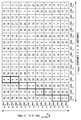
- FIG. 7 An example of resource block set selection according to the first example is shown in FIG.
- FIG. 7 shows only the first 4 subframes among the 16 subframes in the resource pool.
- the numerical value written in each square (cell) shown in FIG. 7 is the value of the resource value n PSDCH that UE1 can select.
- the transmission of the first subframe l 0 PSDCH uses the two most adjacent resource block sets, but the second and third sub-blocks.
- the frequency domain shift value from the second resource block set used in PSDCH transmission is a serial number (ie, 0, 1, ..., (M When RB PSDCH_RP / 2 ⁇ 1 )) is an odd number, it is determined that the first resource block set is included in the first PRB cluster.
- the serial number (ie, 0, 1, ..., (M RB PSDCH_RP / 2-1 )) representing the frequency domain position of the second resource block set is an even number
- a resource block set is determined to be included in the second PRB cluster.
- To the second transmission uses the resource block set in the second PRB cluster.
- two UEs 1 that perform the first PSDCH transmission using two adjacent resource block sets in a certain PRB cluster are PSDCH transmission can be performed using resource block sets in different PRB clusters.
- each of the first and second PRB clusters is composed of resource blocks that are continuous in the frequency domain, but the first PRB cluster and the second PRB cluster are the same. Note that there is a discontinuity in the frequency domain between clusters. Therefore, according to the first example shown in FIG. 7, it is possible to reliably avoid occurrence of large in-band interference in all of the multiple PSDCH transmissions of two UEs 1 using the same plurality of subframes. .
- mapping between resource value n PSDCH and radio resource will be described.
- the second example is inversely related to the first example described above. That is, in the second example, a j for determining the resource block set used in the j-th transmission is defined as follows:
- a j-1 of the value corresponding to the value (a j-1 -1) / A j is determined as the sum of 2 and the fixed shift value N f .
- a j-1 represents the frequency domain position of the resource block set (ie, two consecutive resource blocks) for the (j-1) th PSDCH transmission.
- a j represents the frequency domain position of the resource block set (ie, two consecutive resource blocks) for the j-th PSDCH transmission.
- a j is determined by the value a j-1/2 corresponding to the value of a j-1.
- FIG. 8 An example of resource block set selection according to the second example is shown in FIG.
- FIG. 8 shows only the first four subframes of the 16 subframes in the resource pool, as in FIG.
- the numerical value written in each cell (cell) shown in FIG. 8 is the value of the resource value n PSDCH that UE1 can select.
- the frequency domain shift value from the second resource block set used in is a serial number (ie, 0, 1, ..., (M RB PSDCH_RP) representing the frequency domain position of the second resource block set. / 2-When 1)) is even, the first resource block set is determined to be included in the first PRB cluster.
- the serial number (ie, 0, 1, ..., (M RB PSDCH_RP / 2-1 )) representing the frequency domain position of the second resource block set is odd, the first A resource block set is determined to be included in the second PRB cluster.
- the frequency domain shift value of the j-th transmission and the (j-1) -th transmission is the frequency domain position within the PRB cluster or between PRB clusters. It may be determined by performing substitution, interleaving, or cyclic shift.
- FIG. 9 is a block diagram illustrating a configuration example of UE1.
- the Radio-Frequency (RF) transceiver 901 performs analog RF signal processing to communicate with the eNB 2.
- Analog RF signal processing performed by the RF transceiver 901 includes frequency up-conversion, frequency down-conversion, and amplification.
- RF transceiver 901 is coupled with antenna 902 and baseband processor 903. That is, the RF transceiver 901 receives modulation symbol data (or OFDM symbol data) from the baseband processor 903, generates a transmission RF signal, and supplies the transmission RF signal to the antenna 902. Further, the RF transceiver 901 generates a baseband received signal based on the received RF signal received by the antenna 902 and supplies this to the baseband processor 903.
- modulation symbol data or OFDM symbol data
- the baseband processor 903 performs digital baseband signal processing (data plane processing) and control plane processing for wireless communication.
- Digital baseband signal processing consists of (a) data compression / decompression, (b) data segmentation / concatenation, (c) ⁇ transmission format (transmission frame) generation / decomposition, and (d) transmission path encoding / decoding. , (E) modulation (symbol mapping) / demodulation, and (f) generation of OFDM symbol data (baseband OFDM signal) by Inverse Fast Fourier Transform (IFFT).
- control plane processing includes layer 1 (eg, transmission power control), layer 2 (eg, radio resource management, hybrid automatic repeat request (HARQ) processing), and layer 3 (eg, attach, mobility, and call management). Communication management).
- the digital baseband signal processing by the baseband processor 903 includes signal processing of the Packet Data Convergence Protocol (PDCP) layer, Radio Link Control (RLC) layer, MAC layer, and PHY layer. But you can.
- the control plane processing by the baseband processor 903 may include Non-Access Stratum (NAS) protocol, RRC protocol, and MAC CE processing.
- NAS Non-Access Stratum
- the baseband processor 903 includes a modem processor (eg, Digital Signal Processor (DSP)) that performs digital baseband signal processing and a protocol stack processor (eg, Central Processing Unit (CPU), or Micro Processing Unit (CPU) that performs control plane processing. (MPU)).
- DSP Digital Signal Processor
- protocol stack processor eg, Central Processing Unit (CPU), or Micro Processing Unit (CPU) that performs control plane processing. (MPU)
- a protocol stack processor that performs control plane processing may be shared with an application processor 904 described later.
- the application processor 904 is also called a CPU, MPU, microprocessor, or processor core.
- the application processor 904 may include a plurality of processors (a plurality of processor cores).
- the application processor 904 is a system software program (Operating System (OS)) read from the memory 906 or a memory (not shown) and various application programs (for example, a call application, a web browser, a mailer, a camera operation application, music playback)
- OS Operating System
- application programs for example, a call application, a web browser, a mailer, a camera operation application, music playback
- Various functions of UE1 are realized by executing (application).
- the baseband processor 903 and the application processor 904 may be integrated on a single chip, as indicated by the dashed line (905) in FIG.
- the baseband processor 903 and the application processor 904 may be implemented as one System on Chip (SoC) device 905.
- SoC System on Chip
- An SoC device is sometimes called a system Large Scale Integration (LSI) or chipset.
- the memory 906 is a volatile memory, a nonvolatile memory, or a combination thereof.
- the memory 906 may include a plurality of physically independent memory devices.
- the volatile memory is, for example, Static Random Access Memory (SRAM), Dynamic RAM (DRAM), or a combination thereof.
- the non-volatile memory is a mask Read Only Memory (MROM), Electrically Erasable Programmable ROM (EEPROM), flash memory, hard disk drive, or any combination thereof.
- the memory 906 may include an external memory device accessible from the baseband processor 903, the application processor 904, and the SoC 905.
- Memory 906 may include an embedded memory device integrated within baseband processor 903, application processor 904, or SoC 905.
- the memory 906 may include a memory in a Universal Integrated Circuit Card (UICC).
- UICC Universal Integrated Circuit Card
- the memory 906 may store a software module (computer program) including an instruction group and data for performing processing by the UE 1 described in the above-described embodiments.
- the baseband processor 903 or the application processor 904 reads the software module from the memory 906 and executes it, thereby performing the processing of the UE 1 described using the sequence diagram and the flowchart in the above-described embodiment. It may be configured as follows.
- each of the processors included in UE 1 executes one or more programs including a group of instructions for causing a computer to execute the algorithm described with reference to the drawings. To do.
- the program can be stored and supplied to a computer using various types of non-transitory computer readable media.
- Non-transitory computer readable media include various types of tangible storage media (tangible storage medium).
- non-transitory computer-readable media are magnetic recording media (eg flexible disks, magnetic tapes, hard disk drives), magneto-optical recording media (eg magneto-optical discs), Compact Disc Read Only Memory (CD-ROM), CD-ROM R, CD-R / W, semiconductor memory (for example, mask ROM, Programmable ROM (PROM), Erasable PROM (EPROM), flash ROM, Random Access Memory (RAM)).
- the program may also be supplied to the computer by various types of temporary computer-readable media. Examples of transitory computer readable media include electrical signals, optical signals, and electromagnetic waves.
- the temporary computer-readable medium can supply the program to the computer via a wired communication path such as an electric wire and an optical fiber, or a wireless communication path.
- eNB 2 assigns radio resources to UE 1 semi-persistent for discovery signal (PSDCH) transmission.
- PSDCH discovery signal
- UE1 may select the resource block set for the first transmission in each discovery period according to the value of one or more parameters set from eNB2.
- the resource block set after the 2nd transmission in each discovery period may be determined according to the above-mentioned embodiment.
- eNB2 dynamically allocates radio resources for discovery signal (PSDCH) transmission to UE1 every discovery period (PSDCH period). Specifically, UE1 may select the resource block set for the first transmission in each discovery period according to the value of one or more parameters set from eNB2. And the resource block set after the 2nd transmission in each discovery period may be determined according to the above-mentioned embodiment.
- PSDCH discovery signal
- the embodiment described above is not limited to LTE-Advanced IV and its improvements, but may be applied to D2D communication in other mobile communication networks or systems.
Landscapes
- Engineering & Computer Science (AREA)
- Signal Processing (AREA)
- Computer Networks & Wireless Communication (AREA)
- Databases & Information Systems (AREA)
- Mobile Radio Communication Systems (AREA)
Abstract
L'invention concerne un terminal sans fil (1) qui sélectionne, dans un groupe de ressources pendant une période de découverte, NTX ensembles de blocs de ressources à utiliser pour transmettre un signal de découverte NTX fois sur la base d'une première valeur n1 d'une valeur de ressource qui est volontairement sélectionnée par le terminal sans fil (1) ou une première valeur n1 d'un paramètre reçu depuis une station de base (2). La valeur d'un décalage de domaine de fréquence d'un premier ensemble de blocs de ressources, qui est utilisé pour la j-ième transmission (j est un entier égal ou supérieur à 2) d'un signal de découverte pendant la période de découverte, à partir d'un second ensemble de blocs de ressources qui est utilisé pour la j-1-ième transmission, dépend de la première valeur n1 et/ou de l'emplacement du domaine de fréquence du second ensemble de blocs de ressources au sein du groupe de ressources. Il est ainsi possible de supprimer une dégradation dans la qualité de réception d'un signal de découverte provoquée par l'interférence due à des émissions dans la bande (IBE) au moment, par exemple, de la réalisation de la découverte directe dans la communication D2D.
Priority Applications (2)
| Application Number | Priority Date | Filing Date | Title |
|---|---|---|---|
| JP2017525786A JP6747441B2 (ja) | 2015-06-29 | 2016-03-11 | 無線通信のための方法及び装置 |
| US15/740,676 US10511976B2 (en) | 2015-06-29 | 2016-03-11 | Method and apparatus for radio communication |
Applications Claiming Priority (2)
| Application Number | Priority Date | Filing Date | Title |
|---|---|---|---|
| JP2015130460 | 2015-06-29 | ||
| JP2015-130460 | 2015-06-29 |
Publications (1)
| Publication Number | Publication Date |
|---|---|
| WO2017002282A1 true WO2017002282A1 (fr) | 2017-01-05 |
Family
ID=57609079
Family Applications (1)
| Application Number | Title | Priority Date | Filing Date |
|---|---|---|---|
| PCT/JP2016/001367 Ceased WO2017002282A1 (fr) | 2015-06-29 | 2016-03-11 | Procédé et dispositif de communication sans fil |
Country Status (3)
| Country | Link |
|---|---|
| US (1) | US10511976B2 (fr) |
| JP (1) | JP6747441B2 (fr) |
| WO (1) | WO2017002282A1 (fr) |
Cited By (1)
| Publication number | Priority date | Publication date | Assignee | Title |
|---|---|---|---|---|
| CN111642017A (zh) * | 2017-11-02 | 2020-09-08 | Oppo广东移动通信有限公司 | 用于配置资源的方法、终端设备和网络设备 |
Families Citing this family (5)
| Publication number | Priority date | Publication date | Assignee | Title |
|---|---|---|---|---|
| US10536940B2 (en) * | 2016-01-12 | 2020-01-14 | Nokia Solutions And Networks Oy | Discovery signal block mapping |
| CN115665864B (zh) * | 2019-07-08 | 2025-10-28 | 邦克山科技有限责任公司 | 一种被用于无线通信的节点中的方法和装置 |
| CN114143876A (zh) * | 2020-08-13 | 2022-03-04 | 上海朗帛通信技术有限公司 | 一种被用于无线通信的节点中的方法和装置 |
| CN112929973B (zh) * | 2021-02-05 | 2022-08-09 | 之江实验室 | 一种ue间协作的触发方法 |
| CN119174130A (zh) * | 2022-09-30 | 2024-12-20 | 上海诺基亚贝尔股份有限公司 | 用于侧行链路通信的设备、方法和计算机可读介质 |
Citations (1)
| Publication number | Priority date | Publication date | Assignee | Title |
|---|---|---|---|---|
| US20160128093A1 (en) * | 2014-10-31 | 2016-05-05 | Lg Electronics Inc. | Method for avoiding transmitting mac pdu having padding only in a d2d communication system and device therefor |
-
2016
- 2016-03-11 WO PCT/JP2016/001367 patent/WO2017002282A1/fr not_active Ceased
- 2016-03-11 US US15/740,676 patent/US10511976B2/en active Active
- 2016-03-11 JP JP2017525786A patent/JP6747441B2/ja active Active
Patent Citations (1)
| Publication number | Priority date | Publication date | Assignee | Title |
|---|---|---|---|---|
| US20160128093A1 (en) * | 2014-10-31 | 2016-05-05 | Lg Electronics Inc. | Method for avoiding transmitting mac pdu having padding only in a d2d communication system and device therefor |
Non-Patent Citations (1)
| Title |
|---|
| SAMSUNG: "Clarification on power control for D2D and WAN CA", 3GPP TSG-RAN WG1#80 R1- 150708, 13 February 2015 (2015-02-13), XP050933905, Retrieved from the Internet <URL:http://www.3gpp.org/ftp/ tsg_ran/WG1_RL1/TSGR1_80/Docs/R1-150708.zip> * |
Cited By (2)
| Publication number | Priority date | Publication date | Assignee | Title |
|---|---|---|---|---|
| CN111642017A (zh) * | 2017-11-02 | 2020-09-08 | Oppo广东移动通信有限公司 | 用于配置资源的方法、终端设备和网络设备 |
| CN111642017B (zh) * | 2017-11-02 | 2023-07-14 | Oppo广东移动通信有限公司 | 用于配置资源的方法、终端设备和网络设备 |
Also Published As
| Publication number | Publication date |
|---|---|
| US10511976B2 (en) | 2019-12-17 |
| US20180199206A1 (en) | 2018-07-12 |
| JPWO2017002282A1 (ja) | 2018-04-19 |
| JP6747441B2 (ja) | 2020-08-26 |
Similar Documents
| Publication | Publication Date | Title |
|---|---|---|
| JP7810439B2 (ja) | 端末装置の方法および端末装置 | |
| US10904786B2 (en) | Method for using radio interface technology, apparatus, and communications system | |
| JP6822418B2 (ja) | ネットワーク装置、無線端末、及びこれらの方法 | |
| US10085280B2 (en) | Group carrier scheduling for unlicensed long term evolution network | |
| JPWO2016142979A1 (ja) | 無線局、無線端末装置、及びこれらの方法 | |
| WO2018047401A1 (fr) | Dispositif de communication sans fil, procédé et support lisible par ordinateur non transitoire comprenant un programme | |
| JP6747441B2 (ja) | 無線通信のための方法及び装置 | |
| US20170048906A1 (en) | Operation method of communication node supporting device to device communication in communication network | |
| US10993238B2 (en) | Apparatus and method for radio communication | |
| WO2023067998A1 (fr) | Terminal sans fil, nœud de réseau d'accès sans fil et procédés associés | |
| JP6680299B2 (ja) | 無線通信のための方法及び装置 | |
| WO2024011632A1 (fr) | Procédé et appareil de configuration de ressources, dispositif et support de stockage | |
| US20250110098A1 (en) | Terminal, base station, and method for the same |
Legal Events
| Date | Code | Title | Description |
|---|---|---|---|
| 121 | Ep: the epo has been informed by wipo that ep was designated in this application |
Ref document number: 16817396 Country of ref document: EP Kind code of ref document: A1 |
|
| ENP | Entry into the national phase |
Ref document number: 2017525786 Country of ref document: JP Kind code of ref document: A |
|
| NENP | Non-entry into the national phase |
Ref country code: DE |
|
| 122 | Ep: pct application non-entry in european phase |
Ref document number: 16817396 Country of ref document: EP Kind code of ref document: A1 |