WO2017002312A1 - Dispositif d'affichage, procédé d'affichage, et support d'affichage - Google Patents
Dispositif d'affichage, procédé d'affichage, et support d'affichage Download PDFInfo
- Publication number
- WO2017002312A1 WO2017002312A1 PCT/JP2016/002831 JP2016002831W WO2017002312A1 WO 2017002312 A1 WO2017002312 A1 WO 2017002312A1 JP 2016002831 W JP2016002831 W JP 2016002831W WO 2017002312 A1 WO2017002312 A1 WO 2017002312A1
- Authority
- WO
- WIPO (PCT)
- Prior art keywords
- display
- user
- height
- image
- distance
- Prior art date
- Legal status (The legal status is an assumption and is not a legal conclusion. Google has not performed a legal analysis and makes no representation as to the accuracy of the status listed.)
- Ceased
Links
Images






Classifications
-
- G—PHYSICS
- G02—OPTICS
- G02B—OPTICAL ELEMENTS, SYSTEMS OR APPARATUS
- G02B27/00—Optical systems or apparatus not provided for by any of the groups G02B1/00 - G02B26/00, G02B30/00
- G02B27/01—Head-up displays
- G02B27/0101—Head-up displays characterised by optical features
-
- B—PERFORMING OPERATIONS; TRANSPORTING
- B60—VEHICLES IN GENERAL
- B60K—ARRANGEMENT OR MOUNTING OF PROPULSION UNITS OR OF TRANSMISSIONS IN VEHICLES; ARRANGEMENT OR MOUNTING OF PLURAL DIVERSE PRIME-MOVERS IN VEHICLES; AUXILIARY DRIVES FOR VEHICLES; INSTRUMENTATION OR DASHBOARDS FOR VEHICLES; ARRANGEMENTS IN CONNECTION WITH COOLING, AIR INTAKE, GAS EXHAUST OR FUEL SUPPLY OF PROPULSION UNITS IN VEHICLES
- B60K35/00—Instruments specially adapted for vehicles; Arrangement of instruments in or on vehicles
- B60K35/10—Input arrangements, i.e. from user to vehicle, associated with vehicle functions or specially adapted therefor
-
- B—PERFORMING OPERATIONS; TRANSPORTING
- B60—VEHICLES IN GENERAL
- B60K—ARRANGEMENT OR MOUNTING OF PROPULSION UNITS OR OF TRANSMISSIONS IN VEHICLES; ARRANGEMENT OR MOUNTING OF PLURAL DIVERSE PRIME-MOVERS IN VEHICLES; AUXILIARY DRIVES FOR VEHICLES; INSTRUMENTATION OR DASHBOARDS FOR VEHICLES; ARRANGEMENTS IN CONNECTION WITH COOLING, AIR INTAKE, GAS EXHAUST OR FUEL SUPPLY OF PROPULSION UNITS IN VEHICLES
- B60K35/00—Instruments specially adapted for vehicles; Arrangement of instruments in or on vehicles
- B60K35/20—Output arrangements, i.e. from vehicle to user, associated with vehicle functions or specially adapted therefor
- B60K35/21—Output arrangements, i.e. from vehicle to user, associated with vehicle functions or specially adapted therefor using visual output, e.g. blinking lights or matrix displays
- B60K35/213—Virtual instruments
-
- B—PERFORMING OPERATIONS; TRANSPORTING
- B60—VEHICLES IN GENERAL
- B60K—ARRANGEMENT OR MOUNTING OF PROPULSION UNITS OR OF TRANSMISSIONS IN VEHICLES; ARRANGEMENT OR MOUNTING OF PLURAL DIVERSE PRIME-MOVERS IN VEHICLES; AUXILIARY DRIVES FOR VEHICLES; INSTRUMENTATION OR DASHBOARDS FOR VEHICLES; ARRANGEMENTS IN CONNECTION WITH COOLING, AIR INTAKE, GAS EXHAUST OR FUEL SUPPLY OF PROPULSION UNITS IN VEHICLES
- B60K35/00—Instruments specially adapted for vehicles; Arrangement of instruments in or on vehicles
- B60K35/20—Output arrangements, i.e. from vehicle to user, associated with vehicle functions or specially adapted therefor
- B60K35/21—Output arrangements, i.e. from vehicle to user, associated with vehicle functions or specially adapted therefor using visual output, e.g. blinking lights or matrix displays
- B60K35/23—Head-up displays [HUD]
- B60K35/232—Head-up displays [HUD] controlling the projection distance of virtual images depending on the condition of the vehicle or the driver
-
- B—PERFORMING OPERATIONS; TRANSPORTING
- B60—VEHICLES IN GENERAL
- B60R—VEHICLES, VEHICLE FITTINGS, OR VEHICLE PARTS, NOT OTHERWISE PROVIDED FOR
- B60R11/00—Arrangements for holding or mounting articles, not otherwise provided for
- B60R11/02—Arrangements for holding or mounting articles, not otherwise provided for for radio sets, television sets, telephones, or the like; Arrangement of controls thereof
-
- G—PHYSICS
- G02—OPTICS
- G02B—OPTICAL ELEMENTS, SYSTEMS OR APPARATUS
- G02B27/00—Optical systems or apparatus not provided for by any of the groups G02B1/00 - G02B26/00, G02B30/00
- G02B27/0093—Optical systems or apparatus not provided for by any of the groups G02B1/00 - G02B26/00, G02B30/00 with means for monitoring data relating to the user, e.g. head-tracking, eye-tracking
-
- G—PHYSICS
- G02—OPTICS
- G02B—OPTICAL ELEMENTS, SYSTEMS OR APPARATUS
- G02B27/00—Optical systems or apparatus not provided for by any of the groups G02B1/00 - G02B26/00, G02B30/00
- G02B27/01—Head-up displays
- G02B27/0149—Head-up displays characterised by mechanical features
-
- G—PHYSICS
- G09—EDUCATION; CRYPTOGRAPHY; DISPLAY; ADVERTISING; SEALS
- G09G—ARRANGEMENTS OR CIRCUITS FOR CONTROL OF INDICATING DEVICES USING STATIC MEANS TO PRESENT VARIABLE INFORMATION
- G09G3/00—Control arrangements or circuits, of interest only in connection with visual indicators other than cathode-ray tubes
- G09G3/001—Control arrangements or circuits, of interest only in connection with visual indicators other than cathode-ray tubes using specific devices not provided for in groups G09G3/02 - G09G3/36, e.g. using an intermediate record carrier such as a film slide; Projection systems; Display of non-alphanumerical information, solely or in combination with alphanumerical information, e.g. digital display on projected diapositive as background
-
- B—PERFORMING OPERATIONS; TRANSPORTING
- B60—VEHICLES IN GENERAL
- B60K—ARRANGEMENT OR MOUNTING OF PROPULSION UNITS OR OF TRANSMISSIONS IN VEHICLES; ARRANGEMENT OR MOUNTING OF PLURAL DIVERSE PRIME-MOVERS IN VEHICLES; AUXILIARY DRIVES FOR VEHICLES; INSTRUMENTATION OR DASHBOARDS FOR VEHICLES; ARRANGEMENTS IN CONNECTION WITH COOLING, AIR INTAKE, GAS EXHAUST OR FUEL SUPPLY OF PROPULSION UNITS IN VEHICLES
- B60K2360/00—Indexing scheme associated with groups B60K35/00 or B60K37/00 relating to details of instruments or dashboards
- B60K2360/20—Optical features of instruments
- B60K2360/31—Virtual images
-
- B—PERFORMING OPERATIONS; TRANSPORTING
- B60—VEHICLES IN GENERAL
- B60K—ARRANGEMENT OR MOUNTING OF PROPULSION UNITS OR OF TRANSMISSIONS IN VEHICLES; ARRANGEMENT OR MOUNTING OF PLURAL DIVERSE PRIME-MOVERS IN VEHICLES; AUXILIARY DRIVES FOR VEHICLES; INSTRUMENTATION OR DASHBOARDS FOR VEHICLES; ARRANGEMENTS IN CONNECTION WITH COOLING, AIR INTAKE, GAS EXHAUST OR FUEL SUPPLY OF PROPULSION UNITS IN VEHICLES
- B60K2360/00—Indexing scheme associated with groups B60K35/00 or B60K37/00 relating to details of instruments or dashboards
- B60K2360/20—Optical features of instruments
- B60K2360/33—Illumination features
- B60K2360/334—Projection means
-
- G—PHYSICS
- G02—OPTICS
- G02B—OPTICAL ELEMENTS, SYSTEMS OR APPARATUS
- G02B27/00—Optical systems or apparatus not provided for by any of the groups G02B1/00 - G02B26/00, G02B30/00
- G02B27/01—Head-up displays
- G02B27/0101—Head-up displays characterised by optical features
- G02B2027/0118—Head-up displays characterised by optical features comprising devices for improving the contrast of the display / brillance control visibility
- G02B2027/012—Head-up displays characterised by optical features comprising devices for improving the contrast of the display / brillance control visibility comprising devices for attenuating parasitic image effects
- G02B2027/0121—Parasitic image effect attenuation by suitable positioning of the parasitic images
-
- G—PHYSICS
- G02—OPTICS
- G02B—OPTICAL ELEMENTS, SYSTEMS OR APPARATUS
- G02B27/00—Optical systems or apparatus not provided for by any of the groups G02B1/00 - G02B26/00, G02B30/00
- G02B27/01—Head-up displays
- G02B27/0101—Head-up displays characterised by optical features
- G02B2027/0127—Head-up displays characterised by optical features comprising devices increasing the depth of field
-
- G—PHYSICS
- G02—OPTICS
- G02B—OPTICAL ELEMENTS, SYSTEMS OR APPARATUS
- G02B27/00—Optical systems or apparatus not provided for by any of the groups G02B1/00 - G02B26/00, G02B30/00
- G02B27/01—Head-up displays
- G02B27/0101—Head-up displays characterised by optical features
- G02B2027/013—Head-up displays characterised by optical features comprising a combiner of particular shape, e.g. curvature
-
- G—PHYSICS
- G02—OPTICS
- G02B—OPTICAL ELEMENTS, SYSTEMS OR APPARATUS
- G02B27/00—Optical systems or apparatus not provided for by any of the groups G02B1/00 - G02B26/00, G02B30/00
- G02B27/01—Head-up displays
- G02B27/0101—Head-up displays characterised by optical features
- G02B2027/0138—Head-up displays characterised by optical features comprising image capture systems, e.g. camera
-
- G—PHYSICS
- G02—OPTICS
- G02B—OPTICAL ELEMENTS, SYSTEMS OR APPARATUS
- G02B27/00—Optical systems or apparatus not provided for by any of the groups G02B1/00 - G02B26/00, G02B30/00
- G02B27/01—Head-up displays
- G02B27/0101—Head-up displays characterised by optical features
- G02B2027/014—Head-up displays characterised by optical features comprising information/image processing systems
-
- G—PHYSICS
- G02—OPTICS
- G02B—OPTICAL ELEMENTS, SYSTEMS OR APPARATUS
- G02B27/00—Optical systems or apparatus not provided for by any of the groups G02B1/00 - G02B26/00, G02B30/00
- G02B27/01—Head-up displays
- G02B27/0149—Head-up displays characterised by mechanical features
- G02B2027/0154—Head-up displays characterised by mechanical features with movable elements
- G02B2027/0159—Head-up displays characterised by mechanical features with movable elements with mechanical means other than scaning means for positioning the whole image
-
- G—PHYSICS
- G02—OPTICS
- G02B—OPTICAL ELEMENTS, SYSTEMS OR APPARATUS
- G02B27/00—Optical systems or apparatus not provided for by any of the groups G02B1/00 - G02B26/00, G02B30/00
- G02B27/01—Head-up displays
- G02B27/0179—Display position adjusting means not related to the information to be displayed
- G02B2027/0181—Adaptation to the pilot/driver
-
- G—PHYSICS
- G02—OPTICS
- G02B—OPTICAL ELEMENTS, SYSTEMS OR APPARATUS
- G02B27/00—Optical systems or apparatus not provided for by any of the groups G02B1/00 - G02B26/00, G02B30/00
- G02B27/01—Head-up displays
- G02B27/0179—Display position adjusting means not related to the information to be displayed
- G02B2027/0185—Displaying image at variable distance
-
- G—PHYSICS
- G09—EDUCATION; CRYPTOGRAPHY; DISPLAY; ADVERTISING; SEALS
- G09G—ARRANGEMENTS OR CIRCUITS FOR CONTROL OF INDICATING DEVICES USING STATIC MEANS TO PRESENT VARIABLE INFORMATION
- G09G2320/00—Control of display operating conditions
- G09G2320/02—Improving the quality of display appearance
- G09G2320/0257—Reduction of after-image effects
-
- G—PHYSICS
- G09—EDUCATION; CRYPTOGRAPHY; DISPLAY; ADVERTISING; SEALS
- G09G—ARRANGEMENTS OR CIRCUITS FOR CONTROL OF INDICATING DEVICES USING STATIC MEANS TO PRESENT VARIABLE INFORMATION
- G09G2354/00—Aspects of interface with display user
Definitions
- This disclosure relates to a display device that displays an image or the like.
- HUDs head-up displays
- the driver who is the user can view information related to driving (for example, a map, a speedometer, etc.) without moving the line of sight while looking at the outside world in front. You can drive to.
- information related to driving for example, a map, a speedometer, etc.
- the present disclosure provides a display device capable of suppressing the occurrence of double images.
- a display device includes a plate-like light-transmitting display medium and a projection unit that projects light onto the display medium so that light representing the image is reflected by the display medium and directed to the user With. And a projection part changes the display distance between the position of the image visually recognized as a virtual image by a user over a display medium, and a user's eyes by light projection. Further, the display medium is formed such that a wedge angle, which is an angle formed between the front surface and the back surface at a portion at an arbitrary height of the display medium, continuously decreases as the height increases.
- the display device of the present disclosure can suppress the occurrence of double images.
- FIG. 1 is a diagram illustrating a usage example of a display device in an embodiment.
- FIG. 2 is a diagram illustrating an example of an image displayed by the display device 100 according to the embodiment.
- FIG. 3 is a block diagram illustrating a configuration of the projection unit in the embodiment.
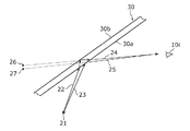
- FIG. 4A is a diagram for explaining an example of a state in which a double image appears.
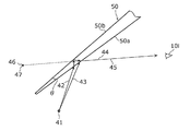
- FIG. 4B is a diagram for describing an example of a state in which the occurrence of double images is suppressed.
- FIG. 5 is a cross-sectional view of the windshield glass in the embodiment.
- FIG. 6 is a diagram illustrating a relationship among the reference height, the reference display distance, and the wedge angle in the embodiment.
- FIG. 7 is a diagram illustrating an example in which an image having a depth is displayed in the embodiment.
- FIG. 8 is a diagram illustrating an example in which the display distance of an image is changed in the embodiment.
- FIG. 9 is a flowchart showing the processing operation of the projection unit in the embodiment.
- FIG. 10 is a diagram illustrating a sheet adjustment width in the embodiment and a range in which the wedge angle in the windshield glass is changed.
- the wedge angle which is the angle formed between the front and back surfaces of the windshield.
- the wedge angle is adjusted so that the image is displayed as a virtual image at a position over the windshield and away from the user by a predetermined distance in the depth direction. Therefore, when such a windshield glass is used to display images as virtual images at different positions in the depth direction, the virtual images may appear as double images.
- a display device configured so that a plate-like light-transmitting display medium and light representing an image are reflected by the display medium and directed to the user. And a projection unit that projects light onto the display medium. And a projection part changes the display distance between the position of the image visually recognized by a user as a virtual image over a display medium, and a user's eyes by light projection.
- the display medium is formed such that the wedge angle, which is an angle formed between the front surface and the back surface at a portion at an arbitrary height of the display medium, continuously decreases as the height increases. .
- the display distance becomes long, that is, when the position of the image visually recognized as a virtual image becomes far in the depth direction, the image appears due to reflection of light at a high part of the display medium.
- the display distance is shortened, that is, when the position of the image visually recognized as a virtual image is close to the depth direction, the image appears due to light reflection at a low part of the display medium.
- the wedge angle there is a one-to-one relationship between the position of an image that appears as a virtual image and the wedge angle. Therefore, when the positions of the images are varied in the depth direction as described above, if the wedge angles are the same at the portions having different heights in the display medium, the above relationship is not satisfied, and a double image is likely to be generated. turn into.
- the wedge angle which is the angle formed between the front surface and the back surface at a portion at an arbitrary height of the display medium, is continuously increased as the height increases. Since the display medium is formed so as to be small, generation of a double image can be suppressed.
- the position of the image when the position of the image is farther in the depth direction as described above, the position of the part of the display medium that reflects light for displaying the image at that position is high, and the wedge angle at that part is small. Therefore, even if the position of the image is far, it is difficult to make the image a double image. Conversely, when the position of the image is close to the depth direction, the position of the portion of the display medium that reflects light for displaying the image at that position is low, and the wedge angle at that portion is large. Therefore, even if the position of the image is close, it is difficult to make the image into a double image. Therefore, even when the position of the image changes in the depth direction, the occurrence of a double image can be suppressed.
- the display device may further include a detection unit that detects the height of the user's eye position, and the projection unit may change the display distance according to the detected height of the eye position.
- the projection unit when the height of the detected eye position is higher than the reference height, the projection unit is configured so that the display distance is longer than the reference display distance when the user's eyes are at the reference height. Change the display distance.
- the projection unit when the height of the detected eye position is lower than the reference height, the projection unit is configured so that the display distance is shorter than the reference display distance when the user's eyes are at the reference height. Change the display distance.
- the display distance is increased by the projection unit, the generation of the double image can be suppressed even when the user's eye position is high.
- the position of the user's eyes is low, a low part of the display medium is used for displaying an image, and the wedge angle at that part is large. Therefore, when the display distance is long, a double image is likely to be generated.
- the display distance is shortened by the projection unit, the generation of the double image can be suppressed even when the user's eye position is low.
- the light of the display medium is The wedge angle at the reflecting part may be adjusted as follows. That is, the first light path from the display medium to the user reflected from one of the front and back surfaces of the display medium and the light reflected from the other of the front and back surfaces from the display medium to the user.
- the wedge angle at the portion of the display medium that reflects the light may be adjusted so that the two optical paths substantially coincide with each other.
- the wedge angle is set so that the first optical path and the second optical path substantially coincide with each other. Due to the adjustment, the occurrence of double images can be sufficiently suppressed.
- the reference height is matched to the height of the standard human eye position, no matter what person tries to view the image as a user, what kind of display the image to be viewed is displayed. Even at a distance, the image can be made difficult to be a double image.
- the display device further includes an adjustment mechanism that adjusts the height of the seat on which the user who visually recognizes the image sits, and when each of the plurality of candidates that are user candidates sits on the seat,
- the adjustment range of the seat height by the adjustment mechanism may be greater than or equal to the maximum value of the seat height difference of the plurality of candidates so that the height of the eye position is also the reference height.
- the height of the eye position of the person can be adjusted to the reference height, and sufficient double image generation is possible for any person. Can be suppressed.
- the display device further includes an adjustment mechanism that adjusts the height of the seat on which the user who views the image is seated, and the adjustment range of the seat height by the adjustment mechanism is set for each of a plurality of candidates of the user sitting on the seat.
- a range in which the line of sight for visually recognizing an image with eyes of different heights of each candidate crosses the display medium, and a range in which the wedge angle continuously changes in the display medium, May be set to substantially match.
- FIG. 1 is a diagram illustrating a usage example of a display device in this embodiment.
- the display device 100 is configured as a so-called head-up display, and includes a projection unit 100a, a windshield (front glass) 100b, and an imaging unit 100c.
- the windshield 100b is a plate-like display medium having translucency.
- the projection unit 100a is attached to, for example, the dashboard 301 of the vehicle 300, and projects the light onto the windshield 100b so that the light representing the image is reflected by the windshield 100b and directed to the user 10. Specifically, the projection unit 100a projects light representing the image d1 onto the windshield 100b and reflects the light onto the windshield 100b. This reflected light is directed to the driver who is the user 10. As a result, the user 10 can visually recognize the image d1 that appears as a virtual image on the outside (vehicle outside) of the windshield 100b by the reflected light while looking at the background over the windshield 100b. That is, the display device 100 in the present embodiment displays the image d1 as a virtual image on the outside of the windshield 100b, in other words, over the windshield 100b.
- the image d1 is an image that shows information related to the vehicle 300 or various types of information used to assist the user 10 in driving.
- information is information relating to a warning for an obstacle (another vehicle or a pedestrian), for example.
- the information is information (such as an arrow indicating a right turn direction or a left turn direction) based on a guide route set by the navigation device.
- the information is information such as a current vehicle speed, a guide sign, a map, traffic information, news, weather forecast, time, a smartphone screen connected to the display device 100, or a television program.
- the projection unit 100a changes the position of the image that is visually recognized by the user 10 as a virtual image through the windshield 100b through the light projection along the depth direction connecting the user 10 and the windshield 100b. That is, the projection unit 100a changes a distance L (hereinafter referred to as a display distance) L between the position of the image and the eyes of the user 10.
- the display distance L is, for example, in a range not less than 2.5 m and not more than 20 m.
- the imaging unit 100c is attached, for example, near the ceiling inside the vehicle 300, images a subject including the eyes of the user 10, and outputs imaging data obtained by the imaging to the projection unit 100a.
- the projection unit 100a When the projection unit 100a acquires the imaging data output from the imaging unit 100c, the projection unit 100a detects the height of the eye position of the user 10 based on the imaging data. That is, the projection unit 100a detects the height of the eye position from the ground or the floor of the vehicle 300, for example.
- the display device 100 changes the display distance L based on the height of the eye position.
- FIG. 2 is a diagram illustrating an example of an image d1 displayed by the display device 100 according to the present embodiment.
- the projection unit 100a attached to the dashboard 301 projects light representing the image d1 onto, for example, a projection area near the driver's seat on the windshield 100b.
- the image d1 is displayed as a virtual image on the back side (the vehicle outer side).
- the projection unit 100a may display the image d1 two-dimensionally at different positions of the display distance L, as shown in FIG. 1, and three-dimensionally display one image d1 as shown in FIG. It may be displayed. That is, in the image, the display device 100 may display an image d1 having a shorter display distance L toward the lower side and a longer display distance L toward the upper side, in other words, an image d1 having a depth.
- the display device 100 may display, for example, an image d1 including an arrow indicating a traveling direction of the vehicle 300 that extends far along the road from the vehicle 300 side.
- FIG. 3 is a block diagram showing a configuration of the projection unit 100a in the present embodiment.
- the projection unit 100a is a device that projects light representing the image d1 by, for example, a laser scanning method (raster scanning method) or the like, and includes a light source 101, a MEMS (Micro Electro Mechanical Systems) mirror 102, an intermediate screen 103, and a projection.
- a mirror 104, an actuator 105, a detection unit 106, and a control unit 110 are provided.
- the light source 101 is a semiconductor laser, for example, and irradiates the MEMS mirror 102 with laser light of each color of R (red), G (green), and B (blue) in accordance with control from the control unit 110. .
- the MEMS mirror 102 reflects the laser beam from the light source 101 and irradiates the intermediate screen 103. At this time, the MEMS mirror 102 swings so that the raster scan to the intermediate screen 103 by the laser light is performed according to the control from the control unit 110.
- the intermediate screen 103 is a translucent screen. An image appears on the irradiation surface of the intermediate screen 103 by the raster scan of the laser beam on the irradiation surface on the MEMS mirror 102 side. Further, since the intermediate screen 103 is translucent, the same image as the image on the irradiation surface appears on the transmission surface that is the surface opposite to the irradiation surface of the intermediate screen 103.
- the projection mirror 104 includes at least one mirror, receives image light representing light that appears on the transmission surface of the intermediate screen 103, and reflects the image light toward the windshield 100b. The image light is further reflected by the windshield 100b and travels toward the eye 10i of the user 10.
- the projection mirror 104 may be comprised from one mirror, and may be comprised from the some mirror.
- Actuator 105 moves the position of intermediate screen 103 back and forth in accordance with control from control unit 110.
- the intermediate screen 103 moves forward, that is, toward the projection mirror 104, the display distance L of the image d1 that appears as a virtual image becomes shorter. That is, the image d1 is close.
- the intermediate screen 103 moves later, that is, toward the MEMS mirror 102, the display distance L of the image d1 becomes longer. That is, the virtual image of the image d1 becomes far away.
- the detecting unit 106 acquires the imaging data from the imaging unit 100c, and detects the height of the position of the user's eye 10i based on the imaging data. Then, the detection unit 106 outputs an adjustment height signal indicating the height to the control unit 110.
- the control unit 110 acquires image data indicating the content of the image d1 from a device external to the projection unit 100a, and controls the light source 101, the MEMS mirror 102, and the actuator 105 based on the image data.
- the control unit 110 calculates the difference between the height indicated by the adjustment height signal and the reference height as the adjustment height. For example, when the height is higher than the reference height, the control unit 110 causes the actuator so that the display distance of the image d1 becomes longer as the adjustment height becomes larger, and the display distance of the image d1 becomes shorter as the adjustment height becomes smaller. 105 is controlled.
- FIG. 4A is a diagram for explaining an example of a state in which a double image appears.
- the double image is generated, for example, when the front surface 30a that is the vehicle inner surface of the windshield 30 and the rear surface 30b that is the vehicle outer surface are parallel to each other.
- the first optical path includes an optical path 22 and an optical path 24. That is, in the first optical path, the light from the light source 21 travels along the optical path 22 toward the windshield 30, passes through the front surface 30 a of the windshield 30, and reflects off the back surface 30 b. The reflected light travels along the optical path 24 from the surface 30a to the user's eye 10i.
- the second optical path includes an optical path 23 and an optical path 25.
- the light from the light source 21 travels along the optical path 23 toward the windshield 30 and is reflected by the surface 30 a of the windshield 30.
- the reflected light travels along the optical path 25 from the surface 30a to the user's eye 10i.
- the optical path 24 in the first optical path and the optical path 25 in the second optical path do not match. Therefore, the virtual image 26 of the light source 21 based on the first optical path and the virtual image 27 of the light source 21 based on the second optical path appear at different positions. Thereby, a double image (ghost) appears.
- FIG. 4B is a diagram for explaining an example in which the occurrence of double images is suppressed.
- the cross section of the windshield 50 is formed in a wedge shape in order to suppress the occurrence of double images. That is, the wedge angle, which is the angle formed between the front surface 30a of the windshield 50 and the back surface 30b of the vehicle outer surface, is adjusted to a value greater than 0 and a finite numerical value ⁇ . Even with such a windshield 50, there are two light paths of light from the light source 41 to the user's eye 10i. However, the optical path from the windshield 50 to the eye 10i in each optical path is the same.
- the first optical path includes the optical path 42 and the optical path 44.
- the light from the light source 41 travels along the optical path 42 toward the windshield 50, passes through the surface 50a of the windshield 50, and is reflected by the back surface 50b.
- the reflected light travels along the optical path 44 from the surface 50a to the user's eye 10i.
- the second optical path includes an optical path 43 and an optical path 45.
- light from the light source 41 is directed to the windshield 50 along the optical path 43 and reflected by the surface 50 a of the windshield 50.
- the reflected light travels along the optical path 45 from the surface 50a toward the user's eye 10i.
- the optical path 44 in the first optical path coincides with the optical path 45 in the second optical path. Therefore, the virtual image 46 of the light source 41 based on the first optical path and the virtual image 47 of the light source 41 based on the second optical path appear at the same position. Thereby, generation
- the cross section of the windshield is wedged. Even if it is formed in a shape, a double image is produced.
- the wedge angle ⁇ is an angle adjusted so that an image appearing as a virtual image at a predetermined display distance does not become a double image, and when the display distance is changed from the predetermined display distance, An image is produced.
- an image at a position where the display distance L is short that is, a close image can be clearly displayed while suppressing the occurrence of double images, but conversely, a position where the display distance L is long.
- a double image is generated.
- an image at a position where the display distance L is long that is, a distant image can be clearly displayed while suppressing the occurrence of double images, but conversely, at a position where the display distance L is short.
- the wedge angle which is an angle formed between the front surface and the back surface at a portion at an arbitrary height of the windshield glass 100b, is continuous as the height increases. It is formed to be smaller.
- FIG. 5 is a cross-sectional view of the windshield 100b in the present embodiment.
- the windshield 100b in the present embodiment is formed such that the wedge angle at the position continuously decreases as the position of the windshield 100b in the height direction increases.
- the heights of the four positions H1b to H4b on the back surface 100bb of the windshield 100b increase in the order of the position H1b, the position H2b, the position H3b, and the position H4b.
- the wedge angle ⁇ 1 at the position H1b is an angle formed between the tangent at the position H1b of the back surface 100bb and the tangent at the position H1a of the front surface 100ba.
- the position H1a and the position H1b are positions optically associated with each other based on the line of sight Li1 from the user's eye 10i.
- the wedge angle ⁇ 2 at the position H2b is an angle formed between the tangent at the position H2b of the back surface 100bb and the tangent at the position H2a of the front surface 100ba.
- the position H2a and the position H2b are positions that are optically associated with each other based on the line of sight Li2 from the user's eye 10i.
- the wedge angle ⁇ 3 at the position H3b is an angle formed between the tangent at the position H3b of the back surface 100bb and the tangent at the position H3a of the front surface 100ba.
- the position H3a and the position H3b are positions optically associated with each other based on the line of sight Li3 from the user's eye 10i.
- the wedge angle ⁇ 4 at the position H4b is an angle formed between the tangent at the position H4b of the back surface 100bb and the tangent at the position H4a of the front surface 100ba.
- the position H4a and the position H4b are positions optically associated with each other based on the line of sight Li4 from the user's eye 10i.
- the wedge angles at the respective positions H1b to H4b satisfy the relationship of ⁇ 1> ⁇ 2> ⁇ 3> ⁇ 4.
- the relationship between the position in the height direction of the windshield 100b and the wedge angle is not limited to the position between the above-described positions H1b to H4b and the wedge angles ⁇ 1 to ⁇ 4, and an arbitrary plurality of positions and their positions. It is also satisfied between the wedge angle at.
- the user tries to look at the upper side of the windshield 100b as the display distance L of the image (virtual image) to be viewed is longer. Conversely, the user tries to look at the lower side of the windshield 100b as the display distance L of the image to be viewed is shorter. That is, the user tries to see the image at the position of the short display distance L according to the line of sight Li1, and tries to see the image at the position of the slightly longer display distance L according to the line of sight Li2 directed upward from the line of sight Li1. To do.
- the user tries to view an image at a position with a long display distance L according to the line of sight Li3 directed upward from the line of sight Li2, and the display distance longer according to the line of sight Li4 directed upward from the line of sight Li3. Try to see the image at position L.
- the user tries to look at the lower side of the windshield 100b as the display distance L of the image to be viewed is shorter. Therefore, the wedge according to the user's line of sight at that time The corner can be increased. As a result, the display device 100 according to the present embodiment can clearly display the close image while suppressing the occurrence of double images.
- the image d1 that appears as a virtual image at a position away from the user's eye 10i by the reference display distance in the depth direction is clearly displayed with sufficiently suppressed generation of a double image.
- the wedge angle of the windshield 100b is adjusted.
- FIG. 6 is a diagram showing the relationship among the reference height, the reference display distance, and the wedge angle.
- the reference height Hs is a predetermined height from the ground or the floor of the vehicle 300, for example.
- the reference display distance Ls is an intermediate distance between the shortest distance Lmin and the longest distance Lmax in the displayable range, which is the range that the display distance L can take.
- the displayable range is determined by the movement width of the intermediate screen 103 that is moved by the actuator 105.
- the double angle is sufficiently suppressed as the wedge angle ⁇ s at a specific part of the windshield 100b. It has been adjusted to be.
- the specific part of the windshield 100b that reflects the light projected from the projection unit 100a and that appears as a virtual image at the position of the reference display distance Ls is directed toward the eye 10i of the user 10 at the reference height Hs. It is a part. That is, similarly to the example shown in FIG. 4B, the wedge angle at the above-described specific part that reflects the light of the windshield 100b is adjusted to ⁇ s so that the two optical paths substantially coincide.
- the first optical path of the two optical paths is an optical path in which light reflected by one of the front and back surfaces of the windshield 100b travels from the windshield 100b to the user 10.
- the 2nd optical path of two optical paths is an optical path from which the light reflected by the other of the surface and a back surface goes to the user 10 from the windshield 100b.
- the first optical path and the second optical path are Since the wedge angle is adjusted so that they substantially coincide with each other, generation of a double image can be sufficiently suppressed.
- the reference height Hs is matched with the height of the standard human eye position, no matter what person tries to view the image as the user, what kind of image is viewed Even at the display distance L, it is possible to make it difficult to form a double image.
- the display device 100 may include an adjustment mechanism 100d that adjusts the height of the seat 302 on which the user who views the image d1 sits.
- An adjustment range of the height of the sheet 302 by the adjustment mechanism 100d is, for example, 200 mm or more. That is, when any of the plurality of candidates of the user 10 sits on the sheet 302, the height of the sheet 302 is adjusted by the adjustment mechanism 100d so that the eye height of any candidate becomes the reference height Hs.
- the range is set to be equal to or greater than the maximum value of the sitting height difference among the plurality of candidates.
- the height of the eye position of the person can be adjusted to the reference height Hs, and a double image can be generated for any person. It can be suppressed sufficiently.
- FIG. 7 is a diagram illustrating an example of a state in which an image having a depth is displayed.
- the display device 100 displays an arrow d2 that is a deep image.
- the arrow d2 indicates the traveling direction of the vehicle 300, for example, and the root of the arrow d2 is displayed nearby. And each part along the depth direction of arrow d2 is displayed farther as the part closer to the tip. That is, the display distance L1 at the base position P5 of the arrow d2, the display distance L2 at the position P6 at the center of the arrow d2, and the display distance L3 at the position P7 at the tip of the arrow d2 are L1 ⁇ L2 ⁇ L3. There is a relationship.
- the projection unit 100a displays the arrow d2 having a portion with a different display distance by performing a raster scan while moving the intermediate screen 103.
- the user turns his gaze downward. That is, the user's eye 10i is directed to the positions 5a and 5b on the lower side of the windshield 100b.
- the user turns his line of sight slightly upward. That is, the user's eye 10i is directed to the positions 6a and 6b that are above the positions 5a and 5b of the windshield 100b.
- the user turns his line of sight further upward. That is, the user's eye 10i is directed to the positions 7a and 7b that are above the positions 6a and 6b of the windshield 100b.
- FIG. 8 is a diagram illustrating an example of a state in which the display distance of the image is changed.
- the display device 100 displays an arrow d2 that is an image having a depth, as in the example shown in FIG.
- the imaging unit 100c images a subject including the user's eyes.
- the detection part 106 in the projection part 100a detects the height of the position of a user's eye 10i based on the imaging data which shows the imaging result. If the detected height (detected height) of the user's eye 10i of the user is a predetermined reference height Hs, the control unit 110, as shown in FIG.
- the actuator 105 is moved so as to be displayed in the range of ⁇ L3.
- the controller 110 moves the actuator 105 so that the arrow d2 is displayed in the display distances L4 to L5 as shown in FIG. .
- the range of the display distances L4 to L5 is farther from the user's eye 10i than the range of the display distances L1 to L3.
- the control unit 110 calculates the adjustment height by subtracting the reference height Hs from the detected height. Then, the control unit 110 moves the actuator 105 so that the arrow d2 is displayed at a position (range) farther away from the user's eye 10i as the adjustment height increases. Conversely, if the detected height is lower than the reference height, the controller 110 moves the actuator 105 so that the arrow d2 is displayed in a range closer to the user's eye 10i than the range of the display distances L1 to L3.
- FIG. 9 is a flowchart showing the processing operation of the projection unit 100a in the present embodiment.
- the detection unit 106 of the projection unit 100a detects the height of the user's eye position as the detection height (step S10).
- the control unit 110 of the projection unit 100a calculates the adjustment height by subtracting the reference height Hs from the detected height (step S11).
- the control part 110 changes the display distance L according to the adjustment height (step S12).
- the projection unit 100a sets the display distance L, which is the distance in the depth direction, between the user's eye 10i and the position where the image appears as a virtual image, as the height of the detected position of the eye 10i. Change accordingly. Specifically, when the height of the detected position of the eye 10i is higher than the reference height, the projection unit 100a determines that the display distance L is the reference display distance when the user's eye 10i is at the reference height. The display distance L is changed so as to be longer. That is, the control unit 110 sets the display distance L to the display distance L4 so that the base display distance L of the arrow d2 is longer than the reference display distance L1 when the user's eye 10i is at the reference height Hs. change.
- the projection unit 100a determines that the display distance L is the reference display distance when the user's eye 10i is at the reference height.
- the display distance L is changed so as to be shorter. That is, the control unit 110 changes the display distance L so that the base display distance L of the arrow d2 is shorter than the reference display distance L1 when the user's eye 10i is at the reference height Hs.
- the display distance L is changed according to the height of the position of the user's eye 10i, but the occurrence of a double image may be suppressed by the adjustment mechanism of the sheet 302.
- the adjustment range the entire adjustable range
- the double image can be suppressed to be negligible without changing the display distance L for each user.
- the adjustment range is 150 mm or more, the change width of the display distance L that is changed for each user can be kept small, and an image can be displayed to each user without causing a sense of incongruity in the display distance. Can be displayed.
- the range in which the wedge angle continuously changes in the windshield 100b may be the entire windshield 100b or a part of the windshield 100b.
- the adjustment range (sheet adjustment width) of the sheet 302 by the adjustment mechanism 100d may be set according to the range in which the wedge angle changes.
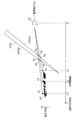
- FIG. 10 is a diagram showing a sheet adjustment width and a range in which the wedge angle in the windshield 100b is changed.
- the seat 302 when a tall user sits on the seat 302 as a driver, the seat 302 is lowered by the adjusting mechanism 100d. Conversely, when a short user sits on the seat 302 as a driver, the seat 302 is raised by the adjusting mechanism 100d.
- the seat adjustment width of the adjustment mechanism 100d is limited, the position of the eye 10i of the tall user is high even if the seat 302 is lowered to the lowest, and the user who is short even if the seat 302 is raised highest. The position of the eye 10i may be lowered. Therefore, even if the height of the seat 302 is adjusted, the position of each user's eye 10i differs between the highest viewpoint position and the lowest viewpoint position.
- the part of the line of sight of the image (virtual image) that appears through the windshield 100b crosses the windshield 100b is It is necessary to be within a range where the wedge angle is changing. That is, the highest line of sight when the eye 10i is at the highest viewpoint position crosses the windshield 100b and the lowest line of sight when the eye 10i is at the lowest viewpoint position crosses the windshield 100b ( The line-of-sight range) matches the range in which the wedge angle changes. In other words, the sheet adjustment width of the adjustment mechanism 100d is set so that the line-of-sight passing range matches the range in which the wedge angle changes.
- the components such as the control unit 110 and the detection unit 106 may be configured by dedicated hardware, or may be realized by executing a software program suitable for each component. Good. Each component may be realized by a program execution unit such as a CPU (Central Processing Unit) or a processor reading and executing a software program recorded on a recording medium such as a hard disk or a semiconductor memory.
- the computer program realizing the display device 100 of the above embodiment causes the computer to execute steps S10 to S12 shown in FIG.
- the display device 100 is for vehicle use, but it may not be for vehicle use.
- the display device 100 may be mounted on eyeglasses configured as a wearable device.
- the display device 100 projects light representing an image onto the left and right lenses (display medium) of the glasses. Even when the display device 100 is mounted on such glasses, the occurrence of double images can be suppressed as in the above embodiment.
- the windshield 100b in the above embodiment may be composed of a single glass plate, or may be composed of an intermediate film and two glass plates sandwiching the intermediate film.
- the material of the interlayer film is not particularly limited as long as it is a transparent thermoplastic resin, and examples thereof include polyvinyl butyral, polyurethane, and ethylene-vinyl acetate copolymer resin.
- the display device 100 changes the display distance L by moving the intermediate screen. However, even if the display distance L is changed by another method such as moving a liquid crystal panel that displays an image. Good.
- the display device 100 has been described based on the above embodiment, but the present invention is not limited to this embodiment. Unless it deviates from the meaning of the present invention, various modifications conceived by those skilled in the art may be included in the scope of the present invention.
- the present invention has the effect of suppressing the occurrence of double images, and can be applied to, for example, an in-vehicle head-up display.
Landscapes
- Engineering & Computer Science (AREA)
- Physics & Mathematics (AREA)
- Mechanical Engineering (AREA)
- General Physics & Mathematics (AREA)
- Optics & Photonics (AREA)
- Chemical & Material Sciences (AREA)
- Combustion & Propulsion (AREA)
- Transportation (AREA)
- Computer Hardware Design (AREA)
- Theoretical Computer Science (AREA)
- Instrument Panels (AREA)
- Fittings On The Vehicle Exterior For Carrying Loads, And Devices For Holding Or Mounting Articles (AREA)
Abstract
L'invention fournit un dispositif d'affichage qui permet d'éviter l'apparition d'image double. Ce dispositif d'affichage (100) est équipé : d'un pare-brise (100b) translucide sous forme de plaque; et d'une partie projection projetant une lumière sur le pare-brise (100b), de sorte que cette lumière présentant une image, est dirigée vers l'utilisateur par réflexion sur le pare-brise (100b). Cette partie projection fait varier la distance d'affichage entre l'œil de l'utilisateur, et la position d'une image vue en tant qu'image virtuelle par l'utilisateur à travers le pare-brise (100b) par projection de la lumière. Le pare-brise (100b) est formé de sorte qu'un angle de coin qui est l'angle formé entre une face avant et une face arrière dans une zone se trouvant à une hauteur arbitraire du pare-brise (100b), diminue continuellement au fur et à mesure que la hauteur s'élève.
Priority Applications (2)
| Application Number | Priority Date | Filing Date | Title |
|---|---|---|---|
| US15/738,645 US10705334B2 (en) | 2015-06-30 | 2016-06-13 | Display device, display method and display medium |
| EP16817424.1A EP3301502B1 (fr) | 2015-06-30 | 2016-06-13 | Dispositif d'affichage, procédé d'affichage, et support d'affichage |
Applications Claiming Priority (2)
| Application Number | Priority Date | Filing Date | Title |
|---|---|---|---|
| JP2015-131926 | 2015-06-30 | ||
| JP2015131926A JP6569898B2 (ja) | 2015-06-30 | 2015-06-30 | 表示装置および表示方法 |
Publications (1)
| Publication Number | Publication Date |
|---|---|
| WO2017002312A1 true WO2017002312A1 (fr) | 2017-01-05 |
Family
ID=57608067
Family Applications (1)
| Application Number | Title | Priority Date | Filing Date |
|---|---|---|---|
| PCT/JP2016/002831 Ceased WO2017002312A1 (fr) | 2015-06-30 | 2016-06-13 | Dispositif d'affichage, procédé d'affichage, et support d'affichage |
Country Status (4)
| Country | Link |
|---|---|
| US (1) | US10705334B2 (fr) |
| EP (1) | EP3301502B1 (fr) |
| JP (1) | JP6569898B2 (fr) |
| WO (1) | WO2017002312A1 (fr) |
Cited By (5)
| Publication number | Priority date | Publication date | Assignee | Title |
|---|---|---|---|---|
| CN106740116A (zh) * | 2017-02-14 | 2017-05-31 | 深圳前海智云谷科技有限公司 | 一种一体式的抬头显示装置 |
| JP2018136362A (ja) * | 2017-02-20 | 2018-08-30 | パナソニックIpマネジメント株式会社 | 画像表示装置 |
| WO2020049873A1 (fr) * | 2018-09-05 | 2020-03-12 | マクセル株式会社 | Dispositif d'affichage tête haute |
| EP3441375B1 (fr) | 2016-04-07 | 2022-01-05 | Agc Inc. | Verre feuilleté |
| JP2023524902A (ja) * | 2020-05-15 | 2023-06-13 | 華為技術有限公司 | コックピットシステム調節装置及びコックピットシステム調節方法 |
Families Citing this family (21)
| Publication number | Priority date | Publication date | Assignee | Title |
|---|---|---|---|---|
| DE102016011354A1 (de) * | 2016-09-20 | 2018-03-22 | Liebherr-Werk Biberach Gmbh | Steuerstand für einen Kran, Bagger und dergleichen |
| WO2018084076A1 (fr) | 2016-11-04 | 2018-05-11 | 富士フイルム株式会社 | Vitre de pare-brise, système d'affichage tête haute, et film demi-miroir |
| JP6839889B2 (ja) * | 2016-12-02 | 2021-03-10 | パナソニックIpマネジメント株式会社 | 表示装置 |
| JP6365646B2 (ja) * | 2016-12-06 | 2018-08-01 | 株式会社Jvcケンウッド | 表示装置及び表示方法 |
| TWI681210B (zh) * | 2017-03-13 | 2020-01-01 | 宏達國際電子股份有限公司 | 頭戴式顯示裝置 |
| FR3067309B1 (fr) * | 2017-06-09 | 2020-02-07 | STMicroelectronics (Grand Ouest) SAS | Procede et systeme de reglage automatique d'au moins un equipement d'un vehicule automobile |
| EP3680700B1 (fr) | 2017-09-07 | 2023-12-27 | FUJIFILM Corporation | Film de miroir unidirectionnel pour afficher des images projetées, verre feuilleté pour afficher des images projetées, et système d'affichage d'image |
| DE102017217023B4 (de) * | 2017-09-26 | 2022-11-03 | Audi Ag | Kraftfahrzeug |
| JP6593461B2 (ja) * | 2018-01-12 | 2019-10-23 | 株式会社Jvcケンウッド | 虚像表示装置 |
| WO2019163969A1 (fr) | 2018-02-23 | 2019-08-29 | 富士フイルム株式会社 | Procédé de fabrication de verre feuilleté pour affichage d'une image, verre feuilleté pour l'affichage d'une image et système d'affichage d'image |
| DE102018213269A1 (de) * | 2018-08-08 | 2020-02-13 | Bayerische Motoren Werke Aktiengesellschaft | Verfahren zum Betreiben einer Blickfeldanzeigevorrichtung für ein Kraftfahr-zeug |
| EP3608174B1 (fr) * | 2018-08-10 | 2021-03-24 | Lg Electronics Inc. | Système d'affichage pour véhicule |
| JP7177176B2 (ja) | 2018-10-17 | 2022-11-22 | 富士フイルム株式会社 | 投映像表示用部材、ウインドシールドガラスおよびヘッドアップディスプレイシステム |
| WO2020122023A1 (fr) | 2018-12-10 | 2020-06-18 | 富士フイルム株式会社 | Élément d'affichage d'image de projection, vitre de pare-brise et système d'affichage tête haute |
| CN113498487B (zh) | 2019-03-06 | 2023-07-04 | 富士胶片株式会社 | 投影图像显示用层叠膜、投影图像显示用的夹层玻璃及图像显示系统 |
| JP6777797B2 (ja) * | 2019-08-21 | 2020-10-28 | マクセル株式会社 | ヘッドアップディスプレイ |
| EP4130812A4 (fr) | 2020-03-30 | 2023-11-22 | FUJIFILM Corporation | Film réfléchissant, verre de pare-brise et système d'affichage tête haute |
| WO2021200652A1 (fr) | 2020-03-30 | 2021-10-07 | 富士フイルム株式会社 | Film de réflexion de lumière à polarisation linéaire, verre de pare-brise et système d'affichage tête haute |
| EP4227718A4 (fr) | 2020-10-09 | 2024-04-03 | FUJIFILM Corporation | Film réfléchissant, verre de pare-brise et système d'affichage tête haute |
| JP7517130B2 (ja) * | 2020-12-14 | 2024-07-17 | 株式会社Jvcケンウッド | 表示装置 |
| JP2025059826A (ja) * | 2023-09-29 | 2025-04-10 | パナソニックオートモーティブシステムズ株式会社 | 表示装置、表示方法及びプログラム |
Citations (6)
| Publication number | Priority date | Publication date | Assignee | Title |
|---|---|---|---|---|
| JPS6438718A (en) * | 1987-04-14 | 1989-02-09 | Horutoroniku G Fur Horogurafui | Display device |
| JP2009184406A (ja) * | 2008-02-04 | 2009-08-20 | Toyota Motor Corp | 車両用ヘッドアップディスプレイ装置 |
| WO2010061835A1 (fr) * | 2008-11-26 | 2010-06-03 | コニカミノルタオプト株式会社 | Dispositif d'affichage d'image et affichage monté en tête |
| JP2011207645A (ja) * | 2010-03-29 | 2011-10-20 | Nippon Sheet Glass Co Ltd | 車両用合わせガラス |
| JP2012058688A (ja) * | 2010-09-13 | 2012-03-22 | Yazaki Corp | ヘッドアップディスプレイ |
| JP2014115417A (ja) * | 2012-12-07 | 2014-06-26 | Denso Corp | ヘッドアップディスプレイ装置 |
Family Cites Families (12)
| Publication number | Priority date | Publication date | Assignee | Title |
|---|---|---|---|---|
| US5013134A (en) * | 1989-09-28 | 1991-05-07 | Hughes Aircraft Company | Ghost-free automotive head-up display employing a wedged windshield |
| EP1093006A4 (fr) * | 1998-06-03 | 2005-06-29 | Nippon Sheet Glass Co Ltd | Dispositif de visualisation tete haute |
| EP1517549A3 (fr) * | 2003-08-27 | 2005-04-20 | Matsushita Electric Industrial Co., Ltd. | Système d'affichage vidéo |
| CN101888927B (zh) | 2007-12-07 | 2013-05-29 | 法国圣戈班玻璃厂 | 由夹层玻璃制成的弧形机动车挡风玻璃 |
| DE102007059323A1 (de) * | 2007-12-07 | 2009-06-10 | Saint-Gobain Sekurit Deutschland Gmbh & Co. Kg | Windschutzscheibe mit einem HUD-Sichtfeld |
| US20120224062A1 (en) * | 2009-08-07 | 2012-09-06 | Light Blue Optics Ltd | Head up displays |
| JP5929691B2 (ja) * | 2012-10-12 | 2016-06-08 | 株式会社Jvcケンウッド | 光走査素子及び表示装置 |
| JP2015034919A (ja) * | 2013-08-09 | 2015-02-19 | 株式会社デンソー | 情報表示装置 |
| EP3176015B1 (fr) * | 2014-07-30 | 2019-04-03 | AGC Inc. | Verre |
| MX2017007407A (es) * | 2014-12-08 | 2017-11-06 | Saint Gobain | Vidrio compuesto que tiene grosor reducido para una pantalla de visualizacion frontal (hud). |
| US10247941B2 (en) * | 2015-01-19 | 2019-04-02 | Magna Electronics Inc. | Vehicle vision system with light field monitor |
| CN105974583B (zh) * | 2015-03-11 | 2019-06-18 | 现代摩比斯株式会社 | 用于车辆的抬头显示器及其控制方法 |
-
2015
- 2015-06-30 JP JP2015131926A patent/JP6569898B2/ja active Active
-
2016
- 2016-06-13 EP EP16817424.1A patent/EP3301502B1/fr active Active
- 2016-06-13 WO PCT/JP2016/002831 patent/WO2017002312A1/fr not_active Ceased
- 2016-06-13 US US15/738,645 patent/US10705334B2/en active Active
Patent Citations (6)
| Publication number | Priority date | Publication date | Assignee | Title |
|---|---|---|---|---|
| JPS6438718A (en) * | 1987-04-14 | 1989-02-09 | Horutoroniku G Fur Horogurafui | Display device |
| JP2009184406A (ja) * | 2008-02-04 | 2009-08-20 | Toyota Motor Corp | 車両用ヘッドアップディスプレイ装置 |
| WO2010061835A1 (fr) * | 2008-11-26 | 2010-06-03 | コニカミノルタオプト株式会社 | Dispositif d'affichage d'image et affichage monté en tête |
| JP2011207645A (ja) * | 2010-03-29 | 2011-10-20 | Nippon Sheet Glass Co Ltd | 車両用合わせガラス |
| JP2012058688A (ja) * | 2010-09-13 | 2012-03-22 | Yazaki Corp | ヘッドアップディスプレイ |
| JP2014115417A (ja) * | 2012-12-07 | 2014-06-26 | Denso Corp | ヘッドアップディスプレイ装置 |
Cited By (8)
| Publication number | Priority date | Publication date | Assignee | Title |
|---|---|---|---|---|
| EP3441375B1 (fr) | 2016-04-07 | 2022-01-05 | Agc Inc. | Verre feuilleté |
| CN106740116A (zh) * | 2017-02-14 | 2017-05-31 | 深圳前海智云谷科技有限公司 | 一种一体式的抬头显示装置 |
| CN106740116B (zh) * | 2017-02-14 | 2023-12-12 | 深圳前海智云谷科技有限公司 | 一种一体式的抬头显示装置 |
| JP2018136362A (ja) * | 2017-02-20 | 2018-08-30 | パナソニックIpマネジメント株式会社 | 画像表示装置 |
| WO2020049873A1 (fr) * | 2018-09-05 | 2020-03-12 | マクセル株式会社 | Dispositif d'affichage tête haute |
| JP2023524902A (ja) * | 2020-05-15 | 2023-06-13 | 華為技術有限公司 | コックピットシステム調節装置及びコックピットシステム調節方法 |
| JP7528261B2 (ja) | 2020-05-15 | 2024-08-05 | 華為技術有限公司 | コックピットシステム調節装置及びコックピットシステム調節方法 |
| US12597274B2 (en) | 2020-05-15 | 2026-04-07 | Shenzhen Yinwang Intelligent Technologies Co., Ltd. | Cockpit system adjustment apparatus and cockpit system adjustment method |
Also Published As
| Publication number | Publication date |
|---|---|
| US10705334B2 (en) | 2020-07-07 |
| JP2017015902A (ja) | 2017-01-19 |
| EP3301502B1 (fr) | 2019-08-14 |
| EP3301502A1 (fr) | 2018-04-04 |
| EP3301502A4 (fr) | 2018-06-27 |
| JP6569898B2 (ja) | 2019-09-04 |
| US20180188530A1 (en) | 2018-07-05 |
Similar Documents
| Publication | Publication Date | Title |
|---|---|---|
| JP6569898B2 (ja) | 表示装置および表示方法 | |
| JP6554175B2 (ja) | ヘッドアップディスプレイ装置 | |
| KR101759945B1 (ko) | 디스플레이 장치 | |
| TWI500966B (zh) | 抬頭顯示器 | |
| JP6558017B2 (ja) | ヘッドアップディスプレイ | |
| JP6269262B2 (ja) | 虚像表示装置 | |
| WO2014208165A1 (fr) | Dispositif d'affichage tête haute | |
| CN110967833B (zh) | 显示装置、显示控制方法及存储介质 | |
| JP6213323B2 (ja) | ヘッドアップディスプレイ装置 | |
| CN210666205U (zh) | 一种抬头显示设备、成像系统和车辆 | |
| CN111727399B (zh) | 显示系统、移动体以及设计方法 | |
| WO2022085621A1 (fr) | Dispositif d'affichage tête haute | |
| JP6784058B2 (ja) | 情報表示装置 | |
| CN111077675A (zh) | 显示装置 | |
| JPWO2020009217A1 (ja) | ヘッドアップディスプレイ装置 | |
| CN110816407A (zh) | 显示装置、显示控制方法及存储介质 | |
| JP6102628B2 (ja) | ヘッドアップディスプレイ装置 | |
| JP7424823B2 (ja) | 画像表示装置 | |
| CN111971197B (zh) | 显示控制装置、平视显示设备 | |
| JP2023076786A (ja) | 虚像表示装置 | |
| CN115480402A (zh) | 显示方法及车辆 | |
| JP2023092264A (ja) | 虚像表示装置 | |
| JP2021021827A (ja) | ヘッドアップディスプレイ |
Legal Events
| Date | Code | Title | Description |
|---|---|---|---|
| 121 | Ep: the epo has been informed by wipo that ep was designated in this application |
Ref document number: 16817424 Country of ref document: EP Kind code of ref document: A1 |
|
| NENP | Non-entry into the national phase |
Ref country code: DE |
|
| WWE | Wipo information: entry into national phase |
Ref document number: 2016817424 Country of ref document: EP |