WO2017002325A1 - Dispositif source d'énergie - Google Patents
Dispositif source d'énergie Download PDFInfo
- Publication number
- WO2017002325A1 WO2017002325A1 PCT/JP2016/002972 JP2016002972W WO2017002325A1 WO 2017002325 A1 WO2017002325 A1 WO 2017002325A1 JP 2016002972 W JP2016002972 W JP 2016002972W WO 2017002325 A1 WO2017002325 A1 WO 2017002325A1
- Authority
- WO
- WIPO (PCT)
- Prior art keywords
- plate
- power supply
- cooling
- supply device
- battery
- Prior art date
- Legal status (The legal status is an assumption and is not a legal conclusion. Google has not performed a legal analysis and makes no representation as to the accuracy of the status listed.)
- Ceased
Links
Images






Classifications
-
- H—ELECTRICITY
- H01—ELECTRIC ELEMENTS
- H01M—PROCESSES OR MEANS, e.g. BATTERIES, FOR THE DIRECT CONVERSION OF CHEMICAL ENERGY INTO ELECTRICAL ENERGY
- H01M10/00—Secondary cells; Manufacture thereof
- H01M10/60—Heating or cooling; Temperature control
- H01M10/61—Types of temperature control
- H01M10/613—Cooling or keeping cold
-
- H—ELECTRICITY
- H01—ELECTRIC ELEMENTS
- H01M—PROCESSES OR MEANS, e.g. BATTERIES, FOR THE DIRECT CONVERSION OF CHEMICAL ENERGY INTO ELECTRICAL ENERGY
- H01M10/00—Secondary cells; Manufacture thereof
- H01M10/60—Heating or cooling; Temperature control
- H01M10/62—Heating or cooling; Temperature control specially adapted for specific applications
- H01M10/625—Vehicles
-
- H—ELECTRICITY
- H01—ELECTRIC ELEMENTS
- H01M—PROCESSES OR MEANS, e.g. BATTERIES, FOR THE DIRECT CONVERSION OF CHEMICAL ENERGY INTO ELECTRICAL ENERGY
- H01M10/00—Secondary cells; Manufacture thereof
- H01M10/60—Heating or cooling; Temperature control
- H01M10/64—Heating or cooling; Temperature control characterised by the shape of the cells
- H01M10/643—Cylindrical cells
-
- H—ELECTRICITY
- H01—ELECTRIC ELEMENTS
- H01M—PROCESSES OR MEANS, e.g. BATTERIES, FOR THE DIRECT CONVERSION OF CHEMICAL ENERGY INTO ELECTRICAL ENERGY
- H01M10/00—Secondary cells; Manufacture thereof
- H01M10/60—Heating or cooling; Temperature control
- H01M10/64—Heating or cooling; Temperature control characterised by the shape of the cells
- H01M10/647—Prismatic or flat cells, e.g. pouch cells
-
- H—ELECTRICITY
- H01—ELECTRIC ELEMENTS
- H01M—PROCESSES OR MEANS, e.g. BATTERIES, FOR THE DIRECT CONVERSION OF CHEMICAL ENERGY INTO ELECTRICAL ENERGY
- H01M10/00—Secondary cells; Manufacture thereof
- H01M10/60—Heating or cooling; Temperature control
- H01M10/65—Means for temperature control structurally associated with the cells
- H01M10/653—Means for temperature control structurally associated with the cells characterised by electrically insulating or thermally conductive materials
-
- H—ELECTRICITY
- H01—ELECTRIC ELEMENTS
- H01M—PROCESSES OR MEANS, e.g. BATTERIES, FOR THE DIRECT CONVERSION OF CHEMICAL ENERGY INTO ELECTRICAL ENERGY
- H01M10/00—Secondary cells; Manufacture thereof
- H01M10/60—Heating or cooling; Temperature control
- H01M10/65—Means for temperature control structurally associated with the cells
- H01M10/655—Solid structures for heat exchange or heat conduction
- H01M10/6551—Surfaces specially adapted for heat dissipation or radiation, e.g. fins or coatings
-
- H—ELECTRICITY
- H01—ELECTRIC ELEMENTS
- H01M—PROCESSES OR MEANS, e.g. BATTERIES, FOR THE DIRECT CONVERSION OF CHEMICAL ENERGY INTO ELECTRICAL ENERGY
- H01M10/00—Secondary cells; Manufacture thereof
- H01M10/60—Heating or cooling; Temperature control
- H01M10/65—Means for temperature control structurally associated with the cells
- H01M10/655—Solid structures for heat exchange or heat conduction
- H01M10/6554—Rods or plates
- H01M10/6555—Rods or plates arranged between the cells
-
- H—ELECTRICITY
- H01—ELECTRIC ELEMENTS
- H01M—PROCESSES OR MEANS, e.g. BATTERIES, FOR THE DIRECT CONVERSION OF CHEMICAL ENERGY INTO ELECTRICAL ENERGY
- H01M10/00—Secondary cells; Manufacture thereof
- H01M10/60—Heating or cooling; Temperature control
- H01M10/65—Means for temperature control structurally associated with the cells
- H01M10/656—Means for temperature control structurally associated with the cells characterised by the type of heat-exchange fluid
- H01M10/6567—Liquids
- H01M10/6568—Liquids characterised by flow circuits, e.g. loops, located externally to the cells or cell casings
-
- H—ELECTRICITY
- H05—ELECTRIC TECHNIQUES NOT OTHERWISE PROVIDED FOR
- H05K—PRINTED CIRCUITS; CASINGS OR CONSTRUCTIONAL DETAILS OF ELECTRIC APPARATUS; MANUFACTURE OF ASSEMBLAGES OF ELECTRICAL COMPONENTS
- H05K7/00—Constructional details common to different types of electric apparatus
- H05K7/20—Modifications to facilitate cooling, ventilating, or heating
-
- H—ELECTRICITY
- H01—ELECTRIC ELEMENTS
- H01M—PROCESSES OR MEANS, e.g. BATTERIES, FOR THE DIRECT CONVERSION OF CHEMICAL ENERGY INTO ELECTRICAL ENERGY
- H01M50/00—Constructional details or processes of manufacture of the non-active parts of electrochemical cells other than fuel cells, e.g. hybrid cells
- H01M50/20—Mountings; Secondary casings or frames; Racks, modules or packs; Suspension devices; Shock absorbers; Transport or carrying devices; Holders
- H01M50/204—Racks, modules or packs for multiple batteries or multiple cells
- H01M50/207—Racks, modules or packs for multiple batteries or multiple cells characterised by their shape
- H01M50/209—Racks, modules or packs for multiple batteries or multiple cells characterised by their shape adapted for prismatic or rectangular cells
-
- H—ELECTRICITY
- H01—ELECTRIC ELEMENTS
- H01M—PROCESSES OR MEANS, e.g. BATTERIES, FOR THE DIRECT CONVERSION OF CHEMICAL ENERGY INTO ELECTRICAL ENERGY
- H01M50/00—Constructional details or processes of manufacture of the non-active parts of electrochemical cells other than fuel cells, e.g. hybrid cells
- H01M50/20—Mountings; Secondary casings or frames; Racks, modules or packs; Suspension devices; Shock absorbers; Transport or carrying devices; Holders
- H01M50/271—Lids or covers for the racks or secondary casings
-
- Y—GENERAL TAGGING OF NEW TECHNOLOGICAL DEVELOPMENTS; GENERAL TAGGING OF CROSS-SECTIONAL TECHNOLOGIES SPANNING OVER SEVERAL SECTIONS OF THE IPC; TECHNICAL SUBJECTS COVERED BY FORMER USPC CROSS-REFERENCE ART COLLECTIONS [XRACs] AND DIGESTS
- Y02—TECHNOLOGIES OR APPLICATIONS FOR MITIGATION OR ADAPTATION AGAINST CLIMATE CHANGE
- Y02E—REDUCTION OF GREENHOUSE GAS [GHG] EMISSIONS, RELATED TO ENERGY GENERATION, TRANSMISSION OR DISTRIBUTION
- Y02E60/00—Enabling technologies; Technologies with a potential or indirect contribution to GHG emissions mitigation
- Y02E60/10—Energy storage using batteries
Definitions
- the present invention relates to a power supply device having a cooling mechanism.
- a vehicle BEV: Battery Electric Vehicle
- HEV Hybrid electric Vehicle
- a power supply device mounted on these electric vehicles a plurality of battery cells are used.
- Each battery cell is a secondary battery that can be charged and discharged, such as a lithium ion battery or a nickel metal hydride battery.
- a typical electric vehicle power supply device includes a plurality of assembled batteries including a plurality of battery cells. By assembling a plurality of battery cells to form an assembled battery, the assemblability of the power supply device can be improved. The number of battery cells of the assembled battery is appropriately determined in consideration of assemblability and workability.
- the power supply device disclosed in Patent Document 1 below includes an assembled battery and a cooling mechanism.
- the assembled battery includes a plurality of assembled battery cells.
- the cooling mechanism includes a plate on which the assembled battery is placed and a cooling pipe for heat exchange. When the temperature of the battery cell rises, the heat of the battery cell is transferred to the plate. Heat exchange between the plate and the cooling pipe is performed via the refrigerant flowing inside the cooling pipe. With the above configuration, the power supply device of Patent Document 1 can cool a plurality of battery cells.
- a main object of the present invention is to provide a technique for preventing a short circuit of an assembled battery caused by blowing of a refrigerant.
- a power supply device includes a plurality of assembled batteries and a plurality of cooling mechanisms for cooling each assembled battery.
- Each cooling mechanism includes a first plate having a placement surface that is in thermal contact with a corresponding battery pack, a second plate fixed to a surface opposite to the placement surface, the first plate, and the first plate.
- the first plate has a side wall that surrounds a region where the seal portion is disposed. The tip of the side wall extends in a direction perpendicular to the mounting surface to a position farther from the corresponding assembled battery than the position of the seal portion.
- the position of the seal portion can be specified as a location where the refrigerant may blow out.
- the refrigerant blown out from the seal portion is blocked by the first plate including the side wall.
- contact between the adjacent assembled battery and the refrigerant can be prevented.
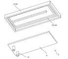
- FIG. 10 is an exploded perspective view of the cooling mechanism of FIG. 9.
- the power supply device 1 includes a plurality of assembled batteries 2 and a plurality of cooling mechanisms 3.
- the plurality of cooling mechanisms 3 are disposed on the frame 4.
- the plurality of assembled batteries 2 are arranged on each cooling mechanism 3.
- the frame 4 includes an exterior case of the power supply device 1 and a vehicle body frame.
- the some assembled battery 2 is located in a matrix form. With such an efficient arrangement, an increase in size of the power supply device 1 is suppressed.
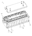
- FIGS. 1 and 2 schematically show the assembled battery 2 and can take various forms as shown in FIGS.
- these assembled batteries 2 have a common cooling surface for heat exchange.
- the cooling surface of the assembled battery 2 is in thermal contact with the cooling mechanism 3.
- Heat exchange between the assembled battery 2 and the cooling mechanism 3 is performed on the cooling surface of the assembled battery.
- An insulating heat conducting member may be disposed between the assembled battery 2 and the cooling mechanism 3. Specifically, heat conducting members such as sheets and gels are known.
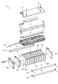
- the battery pack 2A has a battery pack 20A and a fastening portion 25A.
- the battery stack 20A includes a plurality of battery cells and a plurality of insulating spacers 24A.
- Each battery cell is a rectangular battery 21A having a flat rectangular parallelepiped exterior body 22A and an output terminal provided on one surface of the exterior body 22A.
- the exterior body 22A of the prismatic battery 21A is made of metal and has a potential.
- the surface of the outer package 22A may be covered with an insulating layer such as an insulating shrink tube.
- the plurality of prismatic batteries 21A are stacked in one direction so that the wide surfaces of the exterior bodies 22A face each other.
- Each insulating spacer 24A is interposed between adjacent rectangular batteries 21A to prevent contact between the outer casings 22A of adjacent rectangular batteries 21A.
- the fastening portion 25A includes a pair of end plates 26A and a plurality of restraining members 27A.
- the pair of end plates 26A is disposed on each end surface of the battery stack 20A in the stacking direction.
- Each restraining member 27A is fixed to the pair of end plates 26A and extends in the stacking direction of the battery stack 20A.
- the plurality of exterior bodies 22A are formed on the cooling surface of the assembled battery 2. Therefore, each battery cell can be cooled by heat exchange between the assembled battery 2 and the cooling mechanism 3 performed on the cooling surface of the assembled battery 2.
- the assembled battery 2 of an aspect shown in FIG. 5 includes a plurality of battery cells, a rectangular parallelepiped holding portion 23B that holds the plurality of battery cells, and a pair of connection portions 24B for connecting the battery cells.
- Each battery cell is a cylindrical battery 21B having a cylindrical exterior body 22B and an output terminal provided on each end face in the axial direction of the exterior body 22B.
- the outer package 22B of the cylindrical battery 21B is made of metal and has a potential.
- the surface of the exterior body 22B may be covered with an insulating layer such as an insulating shrink tube.
- the holding part 23B is an insulating member having a plurality of through holes.
- the plurality of cylindrical batteries 21B are inserted through the respective through holes of the holding portion 23B.
- the holding unit 23B holds the cylindrical batteries 21B with the output terminals at both ends exposed.
- Each connecting portion 24B includes a conductive plate 25B for connecting the output terminals of the plurality of cylindrical batteries 21B, a bus bar holder 26B for holding the conductive plate 25B, and a cover plate 27B fitted to the bus bar holder 26B.
- the bus bar holder 26B has a plurality of through holes corresponding to the respective cylindrical batteries 21B.
- the bus bar holder 26B is coupled to the end of the holding portion 23B so that the plurality of cylindrical batteries 21B are inserted into the plurality of through holes of the bus bar holder 26B.
- the bus bar holder 26B and the cover plate 27B define an accommodation space for accommodating the conductive plate 25B.
- the accommodation space is filled with resin (not shown).
- the resin filled in the accommodation space has thermal conductivity and insulating properties. Further, the resin filled in the accommodation space is in thermal contact with the plurality of cylindrical batteries 21B and the cover plate 27B.
- one cover plate 27B is positioned on the cooling surface of the assembled battery 2. As described above, the heat of the plurality of cylindrical batteries 21B is transmitted to the cover plate 27B through the resin filled in the accommodation space. Therefore, each battery cell can be cooled by heat exchange between the assembled battery 2 and the cooling mechanism 3 performed on the cooling surface of the assembled battery 2.
- the battery 6 has a battery stack 20C and a fastening portion 25C.
- the battery stack 20C includes a plurality of battery cells, a plurality of heat transfer plates 23C, and a plurality of frames 24C.
- Each battery cell is a pouch battery 21 ⁇ / b> C having a flat sheet-shaped exterior body 22 ⁇ / b> C.
- the exterior body 22C of the pouch battery 21C is formed of a laminate film.
- the laminate film is a composite material in which a resin layer and a metal layer are combined, and has an insulating property. After the power generation element is wrapped with the laminate film, the peripheral portion of the laminate film is thermally welded. In this way, the sealing portion 28C is formed on the periphery of the exterior body 22C.
- An accommodating portion 29C for accommodating the power generation element is formed at the center of the exterior body 22C.
- the plurality of frames 24C are stacked in one direction.
- a pair of pouch batteries 21C that hold one heat transfer plate 23C is disposed between adjacent frame bodies 24C.
- Each frame 24C has an opening at the center. Thereby, a pair of frame 24C avoids the accommodating part 29C of the exterior body 22C, and holds the sealing part 28C.
- the heat transfer plate 23C is in contact with the accommodating portion 29C of the pair of pouch batteries 21C. That is, each heat transfer plate 23C is in thermal contact with the corresponding pair of pouch batteries 21C.
- the fastening portion 25C includes a pair of end plates 26C and a pair of restraining members 27C.
- the pair of end plates 26C is disposed at each end in the stacking direction of the battery stack 20C.
- Each restraining member 27C is fixed to a pair of end plates 26C.
- the restraining member 27C of the assembled battery 2 in FIG. 5 is formed of a metal plate.
- Each heat transfer plate 23 ⁇ / b> C has an L-shaped cross section so as to be in thermal contact with one restraining member 27 ⁇ / b> C.
- one restraining member 27C is positioned on the cooling surface of the assembled battery 2. As described above, the heat of the plurality of pouch batteries 21C is transmitted to the restraining member 27C via each heat transfer plate 23C. Therefore, each battery cell can be cooled by heat exchange between the assembled battery 2 and the cooling mechanism 3 performed on the cooling surface of the assembled battery 2.
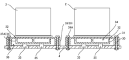
- Each of the cooling mechanisms 3 shown in FIGS. 7 to 10 includes a first plate 30, a second plate 31, and a seal portion 32.
- the first plate 30 is a metal plate on which the assembled battery 2 is placed.
- the assembled battery 2 may be fixed to the first plate 30.
- As means for fixing there are screwing members such as bolts and nuts.
- the first plate 30 has a mounting surface on which the assembled battery 2 is mounted and a flow path forming surface for forming a cooling flow path 34 located on the opposite side of the mounting surface.
- the first plate 30 has a side wall 33 that protrudes from the surface opposite to the placement surface.
- the second plate 31 is fixed to a surface opposite to the mounting surface of the first plate 30.
- the first plate 30 and the second plate 31 are in contact with each other in a region adjacent to the flow path forming surface so that the cooling flow path 34 is formed inside.
- the seal portion 32 is provided in a region where the first plate 30 and the second plate 31 are in contact with each other, and seals the cooling flow path 34.
- a through hole for fixing the first plate 30 and the frame 4 may be provided in the side wall 33.
- the through hole of the side wall 33 extends toward the frame 4.
- the screw member 39 ⁇ / b> A is inserted through the through hole of the side wall 33 to fix the first plate 30 and the frame 4.
- the second plate 31 is indirectly fixed to the frame 4 by being fixed to the first plate 30.
- sticker part 32 is suppressed.
- the above-described fixing structure of the cooling mechanism 3 is only an example. When sufficient strength can be expected, the structure for fixing the cooling mechanism 3 may be different from the above-described structure.
- a pair of pipes 35 serving as an inflow port and an outflow port are attached to each end of the cooling flow path 34.
- the pair of pipes 35 protrudes downward from the bottom surface of the second plate 31.
- the cooling flow path 34 is connected to an external pump (not shown) via a hose (not shown) connected to each pipe 35.
- the pair of pipes 35 are not necessarily provided on the bottom surface of the second plate 31.
- the second plate 31 has a wall portion 37 ⁇ / b> A that protrudes toward the first plate 30.
- the wall portion 37 ⁇ / b> A is annularly provided on the second plate 31.
- the wall portion 37A surrounds the region of the flow path forming surface.
- the wall portion 37A is brazed to the first plate 30.
- an alloy having a lower melting point than the first plate 30 and the second plate 31 is disposed between the first plate 30 and the wall portion 37 ⁇ / b> A of the second plate 31.
- the first plate 30 and the wall portion 37A can be joined by melting the alloy.
- a seal portion 32 is formed at the boundary between the first plate 30 and the second plate 31.
- the seal part 32 seals the cooling flow path 34.
- the rigidity of the seal portion 32 formed of an alloy having a low melting point is smaller than that of the first plate 30 and the second plate 31. According to the above configuration, the position of the seal portion 32 can be specified as a location where the refrigerant may blow out.
- the second plate 31 has a wall portion 37 ⁇ / b> B that protrudes toward the first plate 30.
- the wall portion 37 ⁇ / b> B is provided on the second plate 31 in an annular shape.
- the wall portion 37B includes a flange portion 38B having an insertion hole.
- the first plate 30 and the second plate 31 are fixed via a screwing member 39B such as a bolt inserted into the insertion hole of the flange portion 38B.
- a screwing member 39B such as a bolt inserted into the insertion hole of the flange portion 38B.
- An elastic member is disposed between the first plate 30 and the wall 37 ⁇ / b> B of the second plate 31.
- the first plate 30 and the second plate 31 are fixed via the screwing member 39B, whereby the elastic member is held between the first plate 30 and the wall portion 37B of the second plate 31.
- a seal portion 32 is formed at the boundary between the first plate 30 and the second plate 31.
- the seal part 32 seals the cooling flow path 34.
- the rigidity of the seal portion 32 made of an elastic member is smaller than that of the first plate 30 and the second plate 31. According to the above configuration, the position of the seal portion 32 can be specified as a location where the refrigerant may blow out.
- the elastic member there is a resin member such as an O-ring.
- the first plate 30 has an inner peripheral wall 37 ⁇ / b> C that protrudes toward the second plate 31.
- the inner peripheral wall 37 ⁇ / b> C is an annular wall and is provided inside the side wall 33.
- the inner peripheral wall 37C protrudes from the same plane as the side wall 33.
- the height of the inner peripheral wall 37 ⁇ / b> C is smaller than the height of the side wall 33. Since the inner peripheral wall 37C is fixed to the second plate 31, the inner peripheral wall 37C surrounds the region of the flow path forming surface.
- the inner peripheral wall 37C is brazed to the second plate.
- an alloy having a lower melting point than the first plate 30 and the second plate 31 is disposed between the inner peripheral wall 37 ⁇ / b> C of the first plate 30 and the second plate 31.
- the first plate 30 and the inner peripheral wall 37C can be joined by melting the alloy.
- a seal portion 32 is formed at the boundary between the first plate 30 and the second plate 31.
- the seal part 32 seals the cooling flow path 34.
- the rigidity of the seal portion 32 formed of an alloy having a low melting point is smaller than that of the first plate 30 and the second plate 31. According to the above configuration, the position of the seal portion 32 can be specified as a location where the refrigerant may blow out.
- the tip of the side wall 33 extends downward from the position where the seal portion 32 is provided.
- the tip of the side wall 33 may be configured to extend below the second plate 31 fixed to the first plate 30.
- the first plate 30 including the side wall 33 is interposed between the seal portion 32 and the corresponding assembled battery 2 in the direction of the straight line connecting each assembled battery 2 from the seal portion 32. Therefore, even if the refrigerant blows out from the position of the seal portion 32, the first plate 30 prevents contact between the assembled battery 2 and the refrigerant.
- the cooling mechanism 3 of this configuration ensures that the seal portion 32 is the first plate. 30 is advantageous.
- the shape of the second plate 31 can be a flat plate, and thus there is an advantage that the manufacturing cost of the cooling mechanism 3 is lower than that of the cooling mechanism 3 of FIG. .
- the cooling mechanism 3 may have a water leakage discharge path 36 provided between the side wall 33 and the second plate 31.
- the size of the second plate 31 is smaller than that of the first plate 30. Therefore, the second plate 31 is disposed inside the region surrounded by the side wall 33. According to this configuration, a gap is formed between the side wall 33 of the first plate 30 and the second plate 31. This gap communicates with the space in which the seal portion 32 is provided, and functions as a water leakage discharge path 36.
- the refrigerant blocked by the first plate 30 is quickly discharged to the outside of the cooling mechanism 3 through the water leakage discharge path 36.
- the discharge side path of the water leakage discharge path 36 is configured to extend in a direction perpendicular to the mounting surface of the first plate 30. According to this configuration, even if a large amount of refrigerant leaks, the refrigerant discharged from the water leakage discharge path 36 is guided in a direction away from the assembled battery 2.
- SYMBOLS 1 Power supply device 2 assembled battery, 3 cooling mechanism, 4 frame, 20A battery laminated body, 21A prismatic battery, 22A exterior body, 24A insulating spacer, 25A fastening part, 26A end plate, 27A constraining member, 21B cylindrical battery, 22B Exterior body, 23B holding part, 24B connection part, 25B conductive plate, 26B bus bar holder, 27B cover plate, 20C battery stack, 21C pouch battery, 22C exterior body, 23C heat transfer plate, 24C frame body, 25C fastening part, 26C End plate, 27C restraining member, 28C sealing part, 29C housing part, 30 1st plate, 31 2nd plate, 32 sealing part, 33 side wall, 34 cooling flow path, 35 piping, 36 water leakage discharge path, 37A wall part, 39A screwing member, 37B wall, 8B the flange portion, 39B screwed member, 37C in the circumferential wall
Landscapes
- Engineering & Computer Science (AREA)
- Manufacturing & Machinery (AREA)
- Chemical & Material Sciences (AREA)
- Chemical Kinetics & Catalysis (AREA)
- Electrochemistry (AREA)
- General Chemical & Material Sciences (AREA)
- Physics & Mathematics (AREA)
- Thermal Sciences (AREA)
- Microelectronics & Electronic Packaging (AREA)
- Secondary Cells (AREA)
- Battery Mounting, Suspending (AREA)
- Cooling Or The Like Of Electrical Apparatus (AREA)
Abstract
La présente invention a pour objet d'empêcher un contact entre une batterie assemblée et un réfrigérant adjacents. Ce dispositif source d'énergie est équipé d'une pluralité de batteries assemblées (2) et d'une pluralité de mécanismes de refroidissement servant à refroidir chacune des batteries assemblées (2). Chacun des mécanismes de refroidissement comprend : une première plaque (30) ayant une surface de montage en contact thermique avec la batterie assemblée correspondante (2) ; une seconde plaque (31) fixée sur la surface sur la face inverse de la surface de montage ; un chemin de flux de refroidissement (34) formé entre la première plaque (30) et la seconde plaque (31) ; et une pièce d'étanchéité (32) disposée entre la première plaque (30) et la seconde plaque (31) dans le but d'étanchéifier le chemin de flux de refroidissement (34). La première plaque (30) a une paroi latérale (33) enfermant la région dans laquelle est disposée la pièce d'étanchéité (32). Dans une direction orthogonale à la surface de montage, l'extrémité avant de la paroi latérale (33) s'étend vers une position plus éloignée de la batterie assemblée correspondante (2) que la position de la pièce d'étanchéité (32).
Priority Applications (1)
| Application Number | Priority Date | Filing Date | Title |
|---|---|---|---|
| JP2017526165A JP6500988B2 (ja) | 2015-06-30 | 2016-06-21 | 電源装置 |
Applications Claiming Priority (2)
| Application Number | Priority Date | Filing Date | Title |
|---|---|---|---|
| JP2015130521 | 2015-06-30 | ||
| JP2015-130521 | 2015-06-30 |
Publications (1)
| Publication Number | Publication Date |
|---|---|
| WO2017002325A1 true WO2017002325A1 (fr) | 2017-01-05 |
Family
ID=57608016
Family Applications (1)
| Application Number | Title | Priority Date | Filing Date |
|---|---|---|---|
| PCT/JP2016/002972 Ceased WO2017002325A1 (fr) | 2015-06-30 | 2016-06-21 | Dispositif source d'énergie |
Country Status (2)
| Country | Link |
|---|---|
| JP (1) | JP6500988B2 (fr) |
| WO (1) | WO2017002325A1 (fr) |
Cited By (10)
| Publication number | Priority date | Publication date | Assignee | Title |
|---|---|---|---|---|
| CN110462877A (zh) * | 2017-10-17 | 2019-11-15 | 株式会社Lg化学 | 具有防止泄漏的冷却剂流入的功能的电池组 |
| JP2020035710A (ja) * | 2018-08-31 | 2020-03-05 | 本田技研工業株式会社 | バッテリパックの冷却構造 |
| CN112000147A (zh) * | 2019-05-27 | 2020-11-27 | 马勒国际有限公司 | 温度控制系统 |
| WO2020255885A1 (fr) | 2019-06-21 | 2020-12-24 | 三井化学株式会社 | Dispositif et structure de refroidissement |
| JPWO2021145361A1 (fr) * | 2020-01-17 | 2021-07-22 | ||
| JP2021521620A (ja) * | 2018-04-10 | 2021-08-26 | ソゲフィ・エア・アンド・クーリング | 温度制御手段を組み込んだバッテリユニット |
| CN113415367A (zh) * | 2021-06-17 | 2021-09-21 | 大未来智能科技有限公司 | 一种具有防水功能的共享电动车 |
| CN115621649A (zh) * | 2022-11-08 | 2023-01-17 | 广东顺德电力设计院有限公司 | 电动汽车储能管理控制装置 |
| JP2023063819A (ja) * | 2021-10-25 | 2023-05-10 | マツダ株式会社 | 車両用電池ユニット |
| FR3141809A1 (fr) * | 2022-11-07 | 2024-05-10 | Safran Electrical & Power | Circuit caloporteur de cellules de batterie intégré au socle de ladite batterie et procédé de fabrication associé |
Citations (2)
| Publication number | Priority date | Publication date | Assignee | Title |
|---|---|---|---|---|
| WO2013171885A1 (fr) * | 2012-05-17 | 2013-11-21 | 日立ビークルエナジー株式会社 | Module accumulateur |
| WO2014162939A1 (fr) * | 2013-04-01 | 2014-10-09 | カルソニックカンセイ株式会社 | Dispositif de régulation de température |
-
2016
- 2016-06-21 WO PCT/JP2016/002972 patent/WO2017002325A1/fr not_active Ceased
- 2016-06-21 JP JP2017526165A patent/JP6500988B2/ja active Active
Patent Citations (2)
| Publication number | Priority date | Publication date | Assignee | Title |
|---|---|---|---|---|
| WO2013171885A1 (fr) * | 2012-05-17 | 2013-11-21 | 日立ビークルエナジー株式会社 | Module accumulateur |
| WO2014162939A1 (fr) * | 2013-04-01 | 2014-10-09 | カルソニックカンセイ株式会社 | Dispositif de régulation de température |
Cited By (27)
| Publication number | Priority date | Publication date | Assignee | Title |
|---|---|---|---|---|
| JP2020518944A (ja) * | 2017-10-17 | 2020-06-25 | エルジー・ケム・リミテッド | 漏洩冷媒流入防止機能を有するバッテリーパック |
| EP3614455A4 (fr) * | 2017-10-17 | 2020-10-14 | LG Chem, Ltd. | Bloc-batterie doté d'une fonction empêchant l'entrée d'un liquide de refroidissement qui fuit |
| CN110462877A (zh) * | 2017-10-17 | 2019-11-15 | 株式会社Lg化学 | 具有防止泄漏的冷却剂流入的功能的电池组 |
| US11398655B2 (en) | 2017-10-17 | 2022-07-26 | Lg Energy Solution, Ltd. | Battery pack having function of preventing inflow of leaking coolant |
| CN110462877B (zh) * | 2017-10-17 | 2022-05-03 | 株式会社Lg化学 | 具有防止泄漏的冷却剂流入的功能的电池组 |
| JP7038950B2 (ja) | 2017-10-17 | 2022-03-22 | エルジー エナジー ソリューション リミテッド | 漏洩冷媒流入防止機能を有するバッテリーパック |
| JP7250111B2 (ja) | 2018-04-10 | 2023-03-31 | ソゲフィ・エア・アンド・クーリング | 温度制御手段を組み込んだバッテリユニット |
| JP2021521620A (ja) * | 2018-04-10 | 2021-08-26 | ソゲフィ・エア・アンド・クーリング | 温度制御手段を組み込んだバッテリユニット |
| US11165109B2 (en) | 2018-08-31 | 2021-11-02 | Honda Motor Co., Ltd. | Cooling structure for battery pack |
| JP2020035710A (ja) * | 2018-08-31 | 2020-03-05 | 本田技研工業株式会社 | バッテリパックの冷却構造 |
| CN110931671A (zh) * | 2018-08-31 | 2020-03-27 | 本田技研工业株式会社 | 蓄电池封装体的冷却结构 |
| DE102019207726A1 (de) * | 2019-05-27 | 2020-12-03 | Mahle International Gmbh | Temperiersystem |
| CN112000147B (zh) * | 2019-05-27 | 2022-02-08 | 马勒国际有限公司 | 温度控制系统 |
| US11728529B2 (en) | 2019-05-27 | 2023-08-15 | Mahle International Gmbh | Temperature control system |
| CN112000147A (zh) * | 2019-05-27 | 2020-11-27 | 马勒国际有限公司 | 温度控制系统 |
| WO2020255885A1 (fr) | 2019-06-21 | 2020-12-24 | 三井化学株式会社 | Dispositif et structure de refroidissement |
| KR20220011174A (ko) | 2019-06-21 | 2022-01-27 | 미쯔이가가꾸가부시끼가이샤 | 냉각 장치 및 구조체 |
| WO2021145361A1 (fr) | 2020-01-17 | 2021-07-22 | 三井化学株式会社 | Boîtier, structure et procédé de fabrication de boîtier |
| KR20220101154A (ko) | 2020-01-17 | 2022-07-19 | 미쯔이가가꾸가부시끼가이샤 | 하우징, 구조체 및 하우징의 제조 방법 |
| JPWO2021145361A1 (fr) * | 2020-01-17 | 2021-07-22 | ||
| CN113415367B (zh) * | 2021-06-17 | 2022-06-14 | 大未来智能科技有限公司 | 一种具有防水功能的共享电动车 |
| CN113415367A (zh) * | 2021-06-17 | 2021-09-21 | 大未来智能科技有限公司 | 一种具有防水功能的共享电动车 |
| JP2023063819A (ja) * | 2021-10-25 | 2023-05-10 | マツダ株式会社 | 車両用電池ユニット |
| JP7632228B2 (ja) | 2021-10-25 | 2025-02-19 | マツダ株式会社 | 車両用電池ユニット |
| FR3141809A1 (fr) * | 2022-11-07 | 2024-05-10 | Safran Electrical & Power | Circuit caloporteur de cellules de batterie intégré au socle de ladite batterie et procédé de fabrication associé |
| CN115621649A (zh) * | 2022-11-08 | 2023-01-17 | 广东顺德电力设计院有限公司 | 电动汽车储能管理控制装置 |
| CN115621649B (zh) * | 2022-11-08 | 2023-04-14 | 广东顺德电力设计院有限公司 | 电动汽车储能管理控制装置 |
Also Published As
| Publication number | Publication date |
|---|---|
| JPWO2017002325A1 (ja) | 2018-03-08 |
| JP6500988B2 (ja) | 2019-04-17 |
Similar Documents
| Publication | Publication Date | Title |
|---|---|---|
| JP6500988B2 (ja) | 電源装置 | |
| JP5993615B2 (ja) | 蓄電モジュール | |
| JP5448119B2 (ja) | 改善された冷却効率を有するバッテリ・モジュール | |
| JP5782113B2 (ja) | 新規な構造の冷却部材及びその冷却部材を用いるバッテリーモジュール | |
| CN107799829B (zh) | 电池组以及用于电池组的包封互连 | |
| JP5540114B2 (ja) | 改善された冷却効率の、中型又は大型のバッテリパック | |
| US9935345B2 (en) | Cooling structure of power storage device | |
| KR101854717B1 (ko) | 냉각 플레이트를 포함하는 전지 모듈 및 상기 냉각 플레이트의 제조 방법 | |
| JP5775138B2 (ja) | 電気エネルギー貯蔵装置 | |
| CN104851996A (zh) | 用于电池组的壳体 | |
| CN106463665A (zh) | 用于二次电池的电池电芯组件及包括该组件的二次电池 | |
| JP7442921B2 (ja) | ケースの外部に冷却部を備えたバッテリーパック | |
| KR20140143854A (ko) | 액상 냉매 유출에 대한 안전성이 향상된 전지팩 | |
| KR101960922B1 (ko) | 배터리 모듈 | |
| CN106935927A (zh) | 电池模块和包括其的车辆 | |
| KR20150081579A (ko) | 간접 냉각 구조를 포함하는 전지모듈 | |
| JP5822135B2 (ja) | 蓄電装置 | |
| JP6519428B2 (ja) | 冷却装置およびこの冷却装置を有する電源装置 | |
| JPWO2020054227A1 (ja) | 電源装置 | |
| KR101908441B1 (ko) | 이차전지모듈 | |
| KR20210133538A (ko) | 전지팩 및 이를 포함하는 디바이스 | |
| KR101779944B1 (ko) | 콤팩트하고 안정성이 우수한 냉각부재와 이를 포함하는 전지모듈 | |
| JP2019087416A (ja) | 組電池 | |
| KR20170068439A (ko) | 전지셀 어셈블리 | |
| WO2012121099A1 (fr) | Dispositif de stockage d'électricité |
Legal Events
| Date | Code | Title | Description |
|---|---|---|---|
| 121 | Ep: the epo has been informed by wipo that ep was designated in this application |
Ref document number: 16817437 Country of ref document: EP Kind code of ref document: A1 |
|
| ENP | Entry into the national phase |
Ref document number: 2017526165 Country of ref document: JP Kind code of ref document: A |
|
| NENP | Non-entry into the national phase |
Ref country code: DE |
|
| 122 | Ep: pct application non-entry in european phase |
Ref document number: 16817437 Country of ref document: EP Kind code of ref document: A1 |