WO2017002344A1 - Affichage tête haute et corps mobile le comprenant - Google Patents
Affichage tête haute et corps mobile le comprenant Download PDFInfo
- Publication number
- WO2017002344A1 WO2017002344A1 PCT/JP2016/003053 JP2016003053W WO2017002344A1 WO 2017002344 A1 WO2017002344 A1 WO 2017002344A1 JP 2016003053 W JP2016003053 W JP 2016003053W WO 2017002344 A1 WO2017002344 A1 WO 2017002344A1
- Authority
- WO
- WIPO (PCT)
- Prior art keywords
- light source
- light
- head
- lens
- display
- Prior art date
- Legal status (The legal status is an assumption and is not a legal conclusion. Google has not performed a legal analysis and makes no representation as to the accuracy of the status listed.)
- Ceased
Links
Images




Classifications
-
- G—PHYSICS
- G02—OPTICS
- G02B—OPTICAL ELEMENTS, SYSTEMS OR APPARATUS
- G02B27/00—Optical systems or apparatus not provided for by any of the groups G02B1/00 - G02B26/00, G02B30/00
- G02B27/01—Head-up displays
- G02B27/0101—Head-up displays characterised by optical features
-
- B—PERFORMING OPERATIONS; TRANSPORTING
- B60—VEHICLES IN GENERAL
- B60K—ARRANGEMENT OR MOUNTING OF PROPULSION UNITS OR OF TRANSMISSIONS IN VEHICLES; ARRANGEMENT OR MOUNTING OF PLURAL DIVERSE PRIME-MOVERS IN VEHICLES; AUXILIARY DRIVES FOR VEHICLES; INSTRUMENTATION OR DASHBOARDS FOR VEHICLES; ARRANGEMENTS IN CONNECTION WITH COOLING, AIR INTAKE, GAS EXHAUST OR FUEL SUPPLY OF PROPULSION UNITS IN VEHICLES
- B60K35/00—Instruments specially adapted for vehicles; Arrangement of instruments in or on vehicles
- B60K35/10—Input arrangements, i.e. from user to vehicle, associated with vehicle functions or specially adapted therefor
-
- B—PERFORMING OPERATIONS; TRANSPORTING
- B60—VEHICLES IN GENERAL
- B60K—ARRANGEMENT OR MOUNTING OF PROPULSION UNITS OR OF TRANSMISSIONS IN VEHICLES; ARRANGEMENT OR MOUNTING OF PLURAL DIVERSE PRIME-MOVERS IN VEHICLES; AUXILIARY DRIVES FOR VEHICLES; INSTRUMENTATION OR DASHBOARDS FOR VEHICLES; ARRANGEMENTS IN CONNECTION WITH COOLING, AIR INTAKE, GAS EXHAUST OR FUEL SUPPLY OF PROPULSION UNITS IN VEHICLES
- B60K35/00—Instruments specially adapted for vehicles; Arrangement of instruments in or on vehicles
- B60K35/20—Output arrangements, i.e. from vehicle to user, associated with vehicle functions or specially adapted therefor
- B60K35/21—Output arrangements, i.e. from vehicle to user, associated with vehicle functions or specially adapted therefor using visual output, e.g. blinking lights or matrix displays
- B60K35/23—Head-up displays [HUD]
-
- B—PERFORMING OPERATIONS; TRANSPORTING
- B60—VEHICLES IN GENERAL
- B60K—ARRANGEMENT OR MOUNTING OF PROPULSION UNITS OR OF TRANSMISSIONS IN VEHICLES; ARRANGEMENT OR MOUNTING OF PLURAL DIVERSE PRIME-MOVERS IN VEHICLES; AUXILIARY DRIVES FOR VEHICLES; INSTRUMENTATION OR DASHBOARDS FOR VEHICLES; ARRANGEMENTS IN CONNECTION WITH COOLING, AIR INTAKE, GAS EXHAUST OR FUEL SUPPLY OF PROPULSION UNITS IN VEHICLES
- B60K35/00—Instruments specially adapted for vehicles; Arrangement of instruments in or on vehicles
- B60K35/60—Instruments characterised by their location or relative disposition in or on vehicles
-
- B—PERFORMING OPERATIONS; TRANSPORTING
- B60—VEHICLES IN GENERAL
- B60K—ARRANGEMENT OR MOUNTING OF PROPULSION UNITS OR OF TRANSMISSIONS IN VEHICLES; ARRANGEMENT OR MOUNTING OF PLURAL DIVERSE PRIME-MOVERS IN VEHICLES; AUXILIARY DRIVES FOR VEHICLES; INSTRUMENTATION OR DASHBOARDS FOR VEHICLES; ARRANGEMENTS IN CONNECTION WITH COOLING, AIR INTAKE, GAS EXHAUST OR FUEL SUPPLY OF PROPULSION UNITS IN VEHICLES
- B60K35/00—Instruments specially adapted for vehicles; Arrangement of instruments in or on vehicles
- B60K35/80—Arrangements for controlling instruments
- B60K35/81—Arrangements for controlling instruments for controlling displays
-
- G—PHYSICS
- G02—OPTICS
- G02B—OPTICAL ELEMENTS, SYSTEMS OR APPARATUS
- G02B27/00—Optical systems or apparatus not provided for by any of the groups G02B1/00 - G02B26/00, G02B30/00
- G02B27/0093—Optical systems or apparatus not provided for by any of the groups G02B1/00 - G02B26/00, G02B30/00 with means for monitoring data relating to the user, e.g. head-tracking, eye-tracking
-
- G—PHYSICS
- G02—OPTICS
- G02B—OPTICAL ELEMENTS, SYSTEMS OR APPARATUS
- G02B27/00—Optical systems or apparatus not provided for by any of the groups G02B1/00 - G02B26/00, G02B30/00
- G02B27/01—Head-up displays
- G02B27/0179—Display position adjusting means not related to the information to be displayed
-
- G—PHYSICS
- G06—COMPUTING OR CALCULATING; COUNTING
- G06F—ELECTRIC DIGITAL DATA PROCESSING
- G06F3/00—Input arrangements for transferring data to be processed into a form capable of being handled by the computer; Output arrangements for transferring data from processing unit to output unit, e.g. interface arrangements
- G06F3/01—Input arrangements or combined input and output arrangements for interaction between user and computer
- G06F3/011—Arrangements for interaction with the human body, e.g. for user immersion in virtual reality
- G06F3/013—Eye tracking input arrangements
-
- G—PHYSICS
- G09—EDUCATION; CRYPTOGRAPHY; DISPLAY; ADVERTISING; SEALS
- G09G—ARRANGEMENTS OR CIRCUITS FOR CONTROL OF INDICATING DEVICES USING STATIC MEANS TO PRESENT VARIABLE INFORMATION
- G09G3/00—Control arrangements or circuits, of interest only in connection with visual indicators other than cathode-ray tubes
- G09G3/001—Control arrangements or circuits, of interest only in connection with visual indicators other than cathode-ray tubes using specific devices not provided for in groups G09G3/02 - G09G3/36, e.g. using an intermediate record carrier such as a film slide; Projection systems; Display of non-alphanumerical information, solely or in combination with alphanumerical information, e.g. digital display on projected diapositive as background
-
- G—PHYSICS
- G09—EDUCATION; CRYPTOGRAPHY; DISPLAY; ADVERTISING; SEALS
- G09G—ARRANGEMENTS OR CIRCUITS FOR CONTROL OF INDICATING DEVICES USING STATIC MEANS TO PRESENT VARIABLE INFORMATION
- G09G3/00—Control arrangements or circuits, of interest only in connection with visual indicators other than cathode-ray tubes
- G09G3/20—Control arrangements or circuits, of interest only in connection with visual indicators other than cathode-ray tubes for presentation of an assembly of a number of characters, e.g. a page, by composing the assembly by combination of individual elements arranged in a matrix no fixed position being assigned to or needed to be assigned to the individual characters or partial characters
- G09G3/34—Control arrangements or circuits, of interest only in connection with visual indicators other than cathode-ray tubes for presentation of an assembly of a number of characters, e.g. a page, by composing the assembly by combination of individual elements arranged in a matrix no fixed position being assigned to or needed to be assigned to the individual characters or partial characters by control of light from an independent source
- G09G3/3406—Control of illumination source
-
- G—PHYSICS
- G09—EDUCATION; CRYPTOGRAPHY; DISPLAY; ADVERTISING; SEALS
- G09G—ARRANGEMENTS OR CIRCUITS FOR CONTROL OF INDICATING DEVICES USING STATIC MEANS TO PRESENT VARIABLE INFORMATION
- G09G5/00—Control arrangements or circuits for visual indicators common to cathode-ray tube indicators and other visual indicators
- G09G5/10—Intensity circuits
-
- B—PERFORMING OPERATIONS; TRANSPORTING
- B60—VEHICLES IN GENERAL
- B60K—ARRANGEMENT OR MOUNTING OF PROPULSION UNITS OR OF TRANSMISSIONS IN VEHICLES; ARRANGEMENT OR MOUNTING OF PLURAL DIVERSE PRIME-MOVERS IN VEHICLES; AUXILIARY DRIVES FOR VEHICLES; INSTRUMENTATION OR DASHBOARDS FOR VEHICLES; ARRANGEMENTS IN CONNECTION WITH COOLING, AIR INTAKE, GAS EXHAUST OR FUEL SUPPLY OF PROPULSION UNITS IN VEHICLES
- B60K2360/00—Indexing scheme associated with groups B60K35/00 or B60K37/00 relating to details of instruments or dashboards
- B60K2360/149—Instrument input by detecting viewing direction not otherwise provided for
-
- B—PERFORMING OPERATIONS; TRANSPORTING
- B60—VEHICLES IN GENERAL
- B60K—ARRANGEMENT OR MOUNTING OF PROPULSION UNITS OR OF TRANSMISSIONS IN VEHICLES; ARRANGEMENT OR MOUNTING OF PLURAL DIVERSE PRIME-MOVERS IN VEHICLES; AUXILIARY DRIVES FOR VEHICLES; INSTRUMENTATION OR DASHBOARDS FOR VEHICLES; ARRANGEMENTS IN CONNECTION WITH COOLING, AIR INTAKE, GAS EXHAUST OR FUEL SUPPLY OF PROPULSION UNITS IN VEHICLES
- B60K35/00—Instruments specially adapted for vehicles; Arrangement of instruments in or on vehicles
- B60K35/20—Output arrangements, i.e. from vehicle to user, associated with vehicle functions or specially adapted therefor
- B60K35/21—Output arrangements, i.e. from vehicle to user, associated with vehicle functions or specially adapted therefor using visual output, e.g. blinking lights or matrix displays
- B60K35/211—Output arrangements, i.e. from vehicle to user, associated with vehicle functions or specially adapted therefor using visual output, e.g. blinking lights or matrix displays producing three-dimensional [3D] effects, e.g. stereoscopic images
-
- B—PERFORMING OPERATIONS; TRANSPORTING
- B60—VEHICLES IN GENERAL
- B60R—VEHICLES, VEHICLE FITTINGS, OR VEHICLE PARTS, NOT OTHERWISE PROVIDED FOR
- B60R2300/00—Details of viewing arrangements using cameras and displays, specially adapted for use in a vehicle
- B60R2300/20—Details of viewing arrangements using cameras and displays, specially adapted for use in a vehicle characterised by the type of display used
- B60R2300/205—Details of viewing arrangements using cameras and displays, specially adapted for use in a vehicle characterised by the type of display used using a head-up display
-
- B—PERFORMING OPERATIONS; TRANSPORTING
- B60—VEHICLES IN GENERAL
- B60R—VEHICLES, VEHICLE FITTINGS, OR VEHICLE PARTS, NOT OTHERWISE PROVIDED FOR
- B60R2300/00—Details of viewing arrangements using cameras and displays, specially adapted for use in a vehicle
- B60R2300/60—Details of viewing arrangements using cameras and displays, specially adapted for use in a vehicle characterised by monitoring and displaying vehicle exterior scenes from a transformed perspective
- B60R2300/602—Details of viewing arrangements using cameras and displays, specially adapted for use in a vehicle characterised by monitoring and displaying vehicle exterior scenes from a transformed perspective with an adjustable viewpoint
-
- B—PERFORMING OPERATIONS; TRANSPORTING
- B60—VEHICLES IN GENERAL
- B60R—VEHICLES, VEHICLE FITTINGS, OR VEHICLE PARTS, NOT OTHERWISE PROVIDED FOR
- B60R2300/00—Details of viewing arrangements using cameras and displays, specially adapted for use in a vehicle
- B60R2300/60—Details of viewing arrangements using cameras and displays, specially adapted for use in a vehicle characterised by monitoring and displaying vehicle exterior scenes from a transformed perspective
- B60R2300/602—Details of viewing arrangements using cameras and displays, specially adapted for use in a vehicle characterised by monitoring and displaying vehicle exterior scenes from a transformed perspective with an adjustable viewpoint
- B60R2300/605—Details of viewing arrangements using cameras and displays, specially adapted for use in a vehicle characterised by monitoring and displaying vehicle exterior scenes from a transformed perspective with an adjustable viewpoint the adjustment being automatic
-
- G—PHYSICS
- G02—OPTICS
- G02B—OPTICAL ELEMENTS, SYSTEMS OR APPARATUS
- G02B27/00—Optical systems or apparatus not provided for by any of the groups G02B1/00 - G02B26/00, G02B30/00
- G02B27/01—Head-up displays
- G02B27/0101—Head-up displays characterised by optical features
- G02B2027/0118—Head-up displays characterised by optical features comprising devices for improving the contrast of the display / brillance control visibility
-
- G—PHYSICS
- G02—OPTICS
- G02B—OPTICAL ELEMENTS, SYSTEMS OR APPARATUS
- G02B27/00—Optical systems or apparatus not provided for by any of the groups G02B1/00 - G02B26/00, G02B30/00
- G02B27/01—Head-up displays
- G02B27/0101—Head-up displays characterised by optical features
- G02B2027/0132—Head-up displays characterised by optical features comprising binocular systems
- G02B2027/0134—Head-up displays characterised by optical features comprising binocular systems of stereoscopic type
-
- G—PHYSICS
- G02—OPTICS
- G02B—OPTICAL ELEMENTS, SYSTEMS OR APPARATUS
- G02B27/00—Optical systems or apparatus not provided for by any of the groups G02B1/00 - G02B26/00, G02B30/00
- G02B27/01—Head-up displays
- G02B27/0101—Head-up displays characterised by optical features
- G02B2027/0132—Head-up displays characterised by optical features comprising binocular systems
- G02B2027/0136—Head-up displays characterised by optical features comprising binocular systems with a single image source for both eyes
-
- G—PHYSICS
- G02—OPTICS
- G02B—OPTICAL ELEMENTS, SYSTEMS OR APPARATUS
- G02B27/00—Optical systems or apparatus not provided for by any of the groups G02B1/00 - G02B26/00, G02B30/00
- G02B27/01—Head-up displays
- G02B27/0101—Head-up displays characterised by optical features
- G02B2027/014—Head-up displays characterised by optical features comprising information/image processing systems
-
- G—PHYSICS
- G02—OPTICS
- G02B—OPTICAL ELEMENTS, SYSTEMS OR APPARATUS
- G02B27/00—Optical systems or apparatus not provided for by any of the groups G02B1/00 - G02B26/00, G02B30/00
- G02B27/01—Head-up displays
- G02B27/0179—Display position adjusting means not related to the information to be displayed
- G02B2027/0181—Adaptation to the pilot/driver
-
- G—PHYSICS
- G02—OPTICS
- G02B—OPTICAL ELEMENTS, SYSTEMS OR APPARATUS
- G02B27/00—Optical systems or apparatus not provided for by any of the groups G02B1/00 - G02B26/00, G02B30/00
- G02B27/01—Head-up displays
- G02B27/0179—Display position adjusting means not related to the information to be displayed
- G02B2027/0187—Display position adjusting means not related to the information to be displayed slaved to motion of at least a part of the body of the user, e.g. head, eye
-
- G—PHYSICS
- G02—OPTICS
- G02B—OPTICAL ELEMENTS, SYSTEMS OR APPARATUS
- G02B27/00—Optical systems or apparatus not provided for by any of the groups G02B1/00 - G02B26/00, G02B30/00
- G02B27/01—Head-up displays
- G02B2027/0192—Supplementary details
- G02B2027/0196—Supplementary details having transparent supporting structure for display mounting, e.g. to a window or a windshield
-
- G—PHYSICS
- G09—EDUCATION; CRYPTOGRAPHY; DISPLAY; ADVERTISING; SEALS
- G09F—DISPLAYING; ADVERTISING; SIGNS; LABELS OR NAME-PLATES; SEALS
- G09F9/00—Indicating arrangements for variable information in which the information is built-up on a support by selection or combination of individual elements
-
- G—PHYSICS
- G09—EDUCATION; CRYPTOGRAPHY; DISPLAY; ADVERTISING; SEALS
- G09G—ARRANGEMENTS OR CIRCUITS FOR CONTROL OF INDICATING DEVICES USING STATIC MEANS TO PRESENT VARIABLE INFORMATION
- G09G2320/00—Control of display operating conditions
- G09G2320/06—Adjustment of display parameters
- G09G2320/068—Adjustment of display parameters for control of viewing angle adjustment
-
- G—PHYSICS
- G09—EDUCATION; CRYPTOGRAPHY; DISPLAY; ADVERTISING; SEALS
- G09G—ARRANGEMENTS OR CIRCUITS FOR CONTROL OF INDICATING DEVICES USING STATIC MEANS TO PRESENT VARIABLE INFORMATION
- G09G2330/00—Aspects of power supply; Aspects of display protection and defect management
- G09G2330/02—Details of power systems and of start or stop of display operation
-
- G—PHYSICS
- G09—EDUCATION; CRYPTOGRAPHY; DISPLAY; ADVERTISING; SEALS
- G09G—ARRANGEMENTS OR CIRCUITS FOR CONTROL OF INDICATING DEVICES USING STATIC MEANS TO PRESENT VARIABLE INFORMATION
- G09G2354/00—Aspects of interface with display user
-
- G—PHYSICS
- G09—EDUCATION; CRYPTOGRAPHY; DISPLAY; ADVERTISING; SEALS
- G09G—ARRANGEMENTS OR CIRCUITS FOR CONTROL OF INDICATING DEVICES USING STATIC MEANS TO PRESENT VARIABLE INFORMATION
- G09G3/00—Control arrangements or circuits, of interest only in connection with visual indicators other than cathode-ray tubes
- G09G3/20—Control arrangements or circuits, of interest only in connection with visual indicators other than cathode-ray tubes for presentation of an assembly of a number of characters, e.g. a page, by composing the assembly by combination of individual elements arranged in a matrix no fixed position being assigned to or needed to be assigned to the individual characters or partial characters
-
- G—PHYSICS
- G09—EDUCATION; CRYPTOGRAPHY; DISPLAY; ADVERTISING; SEALS
- G09G—ARRANGEMENTS OR CIRCUITS FOR CONTROL OF INDICATING DEVICES USING STATIC MEANS TO PRESENT VARIABLE INFORMATION
- G09G5/00—Control arrangements or circuits for visual indicators common to cathode-ray tube indicators and other visual indicators
Definitions
- the present disclosure relates to a head-up display that displays an image for allowing an observer to visually recognize a virtual image.
- Patent Document 1 discloses a head-up display that makes light emitted from a light source behind a liquid crystal panel uniform and transmits and illuminates the liquid crystal panel.
- the head-up display includes a light source (light emitting diode), a first condenser lens, a diffusion plate, and a second condenser lens.
- the second condenser lens condenses the light emitted from the light source onto the diffusion plate. Thereby, the brightness nonuniformity can be reduced while suppressing a decrease in the brightness of the illumination light transmitted through the display.
- the head-up display projects an image on the eye box of the observer.
- the head-up display includes a plurality of light source elements, a transmissive display element, an optical member, a viewpoint detection unit, and a control unit.
- the plurality of light source elements are arranged in an array and emit light.
- the transmissive display element displays an image.
- the optical member deflects the light emitted from the plurality of light source elements so as to illuminate the same region on the incident surface of the transmissive display element.
- the viewpoint detection unit detects the position of the observer's eyes.
- the control unit controls the light intensity of the light source element according to the viewpoint position detected by the viewpoint detection unit.
- a moving body (an automobile, a railway vehicle, an aircraft, a ship, or the like) including the head-up display is provided.
- the head-up display in the present disclosure can save power by controlling lighting of the light source according to the position of the observer's eyes.
- FIG. 1 is a schematic diagram showing a vehicle equipped with a head-up display in the first embodiment.
- FIG. 2 is a diagram for explaining the configuration of the display unit of the head-up display in the first embodiment.
- FIG. 3A is a diagram illustrating an optical path (an optical path viewed from the Y-axis direction) of the head-up display in the first embodiment.
- FIG. 3B is a diagram illustrating an optical path (an optical path viewed from the X-axis direction) of the head-up display in the first embodiment.
- FIG. 4A is a diagram showing an optical path viewed from the Y-axis direction in the first embodiment.
- FIG. 4B is a diagram for explaining superimposition of optical paths (optical paths viewed from the X-axis direction) of each light source element.
- FIG. 4C is a diagram showing an optical path viewed from the X-axis direction in the first embodiment.
- FIG. 5A is a graph (X-axis direction center portion) showing a distribution of emitted light of the display unit (liquid crystal panel) in the first exemplary embodiment.
- FIG. 5B is a graph (X-axis direction end portion) showing a distribution of emitted light of the display unit (liquid crystal panel) in the first exemplary embodiment.
- FIG. 5C is a graph (Y-axis direction central portion) showing a distribution of emitted light of the display unit (liquid crystal panel) in the first exemplary embodiment.
- FIG. 5A is a graph (X-axis direction center portion) showing a distribution of emitted light of the display unit (liquid crystal panel) in the first exemplary embodiment.
- FIG. 5B is a graph (X
- FIG. 6A is a diagram illustrating an optical path of the head-up display in the first embodiment.
- FIG. 6B is a diagram illustrating an optical path of the head-up display in the first embodiment.
- FIG. 7A is a diagram illustrating lighting control for each eye box region in the second embodiment.
- FIG. 7B is a diagram illustrating lighting control for each eyebox area in the second embodiment.
- the light emitted from the light source is condensed on the diffusion plate by the second condenser lens. Specifically, light from a plurality of light sources (light emitting diodes) is received by each lens of the plurality of lenses provided in the second condenser lens and emitted to the diffusion plate. That is, light from one light source is received by one lens. For this reason, when light emitted from each lens of the condenser lens is incident on the diffuser plate, luminance unevenness occurs in the vicinity of the boundary of the region irradiated with the light emitted from the adjacent lens in the condenser lens. There is a problem of getting.
- one light source illuminates a part of the display element, and light from all the light source elements reaches the entire eye box regardless of the position of the driver's eyes. In other words, light from the light source is incident in addition to the position of the driver's eyes on the eyebox, and there is a lot of wasted light.
- FIG. 1 is a diagram showing a configuration of a head-up display mounted on a vehicle in the first embodiment.
- the head-up display 100 is mounted on a vehicle 200 (an example of a moving body) that includes a windshield 230.
- the head-up display 100 includes a display unit 120, a reflective optical unit 130, a housing 140, and a viewpoint detection unit 800.
- the display unit 120 includes a lighting device 110, a liquid crystal panel 115, and a control unit 700.
- the head-up display 100 is a device that projects an image for allowing the observer 300 to visually recognize the virtual image 400 on the windshield 230.
- the illumination device 110 illuminates a liquid crystal panel 115 which is a display element.
- the liquid crystal panel 115 displays an image indicating a numerical value indicating a speedometer or speed, for example.
- the liquid crystal panel 115 functions as a spatial light modulator, and modulates the light from the illumination device 110 with the displayed image.
- the modulated light is emitted from the liquid crystal panel 115 as transmitted light.
- the transmitted light is guided into the eye box 600 of the observer 300 through the reflective optical unit 130 and the windshield 230, and is visually recognized as a virtual image 400 by the observer 300.
- the observer 300 can visually recognize an image such as a speedometer as the virtual image 400.
- the eye box is a region that the viewer 300 can visually recognize without missing the virtual image 400.
- the reflective optical unit 130 (an example of an optical element) includes a first mirror 131 and a second mirror 132.
- the first mirror 131 reflects the light emitted from the liquid crystal panel 115 toward the second mirror 132.
- the second mirror 132 reflects the light from the first mirror 131 toward the windshield 230.
- the reflection surface of the second mirror 132 has a concave shape.
- the reflective optical unit 130 does not necessarily need to be composed of two mirrors, and may be composed of one mirror or three or more mirrors. Further, a refractive optical system such as a lens may be further disposed on the optical path of the reflective optical unit 130.
- the housing 140 of the head-up display 100 houses the display unit 120 and the reflective optical unit 130, and has an opening 141 through which light from the reflective optical unit 130 is emitted.
- a transparent cover may be provided in the opening 141.
- the control unit 700 is a processor that controls the lighting device 110 and the liquid crystal panel 115.
- the head-up display 100 is controlled based on information from the viewpoint detection unit 800.
- the viewpoint detection unit 800 is a device that is provided inside the vehicle 200 and detects the positions of the left and right eyes of the observer 300.
- the viewpoint detection unit 800 is an imaging device such as a camera or a sensor using infrared rays, for example.
- FIG. 2 is a diagram showing a detailed configuration of the display unit 120.
- the display unit 120 includes a lighting device 110, a liquid crystal panel 115, and a control unit 700.
- the liquid crystal panel 115 has an incident surface 115a for entering light and an exit surface 115b for emitting light.
- the entrance surface 115a and the exit surface 115b have the same shape and a rectangular shape.
- a three-dimensional orthogonal coordinate system is set in the drawing. That is, the X axis is set in a direction parallel to the longitudinal direction of the incident surface 115a and the exit surface 115b in the liquid crystal panel 115, and the Y axis is set in a direction parallel to the width direction of the entrance surface 115a and the exit surface 115b.
- the Z axis is set in the normal direction of 115a and the exit surface 115b.
- the illumination device 110 includes a plurality of light source elements 111, a first lens 112 arranged in the emission direction of the light source element 111, and a second lens 113 arranged in the emission direction of the first lens 112. And a diffusion plate 114 (an example of a diffusion member) disposed in the emission direction of the second lens 113.
- the light source element 111 is, for example, a chip-type light emitting diode (LED), and is a light emitter that supplies illumination light to the liquid crystal panel 115.
- the plurality of light source elements 111 are arranged in a line in the longitudinal direction (X direction in FIG. 3).
- the first lens 112 is disposed close to the light source element 111 so that the light emitted from each light source element 111 does not leak.
- the 1st lens 112 takes in the emitted light of each light source element 111 from the entrance plane 112a. Further, the first lens 112 has a function of deflecting and emitting the diverging light of the light source element 111 into substantially parallel light in the Y direction. Further, only one first lens 112 is disposed for the plurality of light source elements 111.
- At least one of the entrance surface 112a and the exit surface 112b of the first lens 112 has a convex shape so that the first lens 112 has a positive refractive power.
- the convex shapes of the entrance surface 112a and the exit surface 112b of the first lens 112 do not need to be rotationally symmetric with respect to the optical axis, and may be toroidal shapes having different curvatures in the X direction and the Y direction.
- the first lens 112 is a plano-convex lens having a convex shape only on the emission surface 112b.
- the exit surface 112b of the first lens 112 is a convex surface having an aspherical shape with different curvatures in the X-axis direction and the Y-axis direction.
- the shape of the exit surface 112b in the X-axis direction is such that the curvature decreases from the center to the end so that the illuminance distribution on the diffusion plate 114 of the emitted light from each light source element 111 is uniform (that is, the curvature radius is large).
- the shape of the exit surface 112b in the Y-axis direction has such a shape that the curvature of the end portion is smaller than that of the center portion so that the illuminance distribution is uniform on the diffusion plate 114.
- the second lens 113 has a function of deflecting light emitted from the first lens 112 in a desired direction.
- the incident surface 113a of the second lens 113 has a convex shape only in the X-axis direction.
- the shape of the exit surface 113b of the second lens 113 has a convex shape with different curvatures in the X-axis direction and the Y-axis direction.
- the incident surface 113a of the second lens 113 may have a convex shape having different curvatures in the X-axis direction and the Y-axis direction.
- the emission surface 113b of the second lens 113 may have a shape having a convex shape only in one of the X-axis and Y-axis directions.
- the refractive power of the second lens 113 is set according to the emission angle of the emitted light at the end of the display unit 120 (or the incident angle of the incident light on the diffusion plate 114).
- the second lens 113 is not always necessary. By increasing the distance between the first lens 112 and the diffusion plate 114 without using the second lens 113, it is possible to achieve a desired emission angle at the end of the display unit 120 with only the first lens 112. is there.
- the first lens 112 and the second lens 113 are made of a transparent material having a predetermined refractive index.
- the refractive index of the transparent material is, for example, about 1.4 to 1.6.
- a resin such as an epoxy resin, a silicon resin, an acrylic resin, or polycarbonate can be used.
- polycarbonate is used in consideration of heat resistance.
- the diffusion plate 114 diffuses the light deflected by the first lens 112 and the second lens 113 and emits the light to the liquid crystal panel 115. Thereby, the brightness nonuniformity in the image light produced
- the diffusion plate 114 may be an optical member having a function of diffusing light.
- the surface of the diffusion plate 114 is constituted by a bead member, a fine uneven structure, or a rough surface. Further, a dot sheet or a transparent milky white sheet may be used.
- the control unit 700 controls lighting of the plurality of light source elements 111 based on information from the viewpoint detection unit 800 and the liquid crystal panel 115.
- the control unit 700 can be realized by a microcomputer, for example.
- FIG. 3A and 3B are diagrams showing the optical path from the liquid crystal panel 115 to the eye box 600 in the head-up display 100.
- FIG. The observer 300 visually recognizes the light transmitted through the liquid crystal panel 115 through the virtual image optical system 500.
- the virtual image optical system 500 is a combination of the reflective optical unit 130 and the windshield 230 shown in FIG.
- FIG. 3A shows an optical path when viewed from the long side of the liquid crystal panel 115
- FIG. 3B shows an optical path when viewed from the short side of the liquid crystal panel 115.
- the liquid crystal panel 115 When the liquid crystal panel 115 is arranged so that the incident surface 115 a of the liquid crystal panel 115 is parallel to the emission surface of the illumination device 110, the emitted light from the liquid crystal panel 115 toward the center of the eye box 600 is transmitted from the liquid crystal panel 115.
- the light is emitted at different emission angles at the center and the end. Specifically, the emission angle ⁇ 1 at the center of the liquid crystal panel 115 is larger than the emission angle ⁇ 2 at the end of the liquid crystal panel 115.
- the light emitted from the central portion of the liquid crystal panel 115 is emitted in the normal direction of the light emission surface 115b of the liquid crystal panel 115, while the light emitted from the end portion is emitted toward the outside of the light emission surface 115b of the liquid crystal panel 115. Is done. This is not the case when the liquid crystal panel 115 is not arranged in parallel to the illumination device 110, and the outgoing light at the center is inclined with respect to the normal direction of the outgoing surface 115b of the liquid crystal panel 115. Further, since the eye box 600 generally has a length in the X direction larger than a length in the Y direction, the light distribution angle ⁇ 1 in the X axis direction (see FIG. 3A) is the light distribution angle ⁇ 2 in the Y axis direction ( (See FIG. 3B).
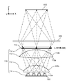
- FIG. 4A is a diagram showing an optical path from the light source element 111 to the eye box 600 as seen from the Y-axis direction.
- the first lens 112 deflects the light emitted from each light source element 111 so that each of the light emitted from the plurality of light source elements 111 overlaps at the position of the diffusion plate 114.
- the refractive power of the first lens 112 is set so that each of the plurality of light source elements 111 illuminates the entire surface of the liquid crystal panel 115 when viewed from the Y-axis direction.
- the light emitted from the light source element 111a and the light emitted from the light source element 111c both illuminate the entire area of the liquid crystal panel 115.
- the other light source elements 111b and 111d both illuminate the entire area of the liquid crystal panel 115.
- the focal length of the first lens 112 is set so that the emitted light from each of the light source elements 111a to 111d is irradiated with the same region of the liquid crystal panel 115 superimposed.
- the first lens 112 is designed so that the focal length of the first lens 112 is the same value as the distance from the optical center of the first lens 112 to the liquid crystal panel 115.
- the focal length of the first lens 112 is set to A value larger than the distance from the optical center to the liquid crystal panel 115 may be set.
- the second lens 113 is used to adjust the incident angle of the light emitted from the first lens 112 to the liquid crystal panel 115. That is, the second lens 113 deflects the light emitted from the first lens 112 in a direction inclined at a predetermined angle.
- This predetermined angle is an angle at which the emission angles at the center and the end of the liquid crystal panel 115 as shown in FIGS. 3A and 3B can be obtained. That is, the refractive power of the second lens 113 is set so that the emission angle according to the virtual image optical system 500 is obtained.
- the second lens 113 is not essential.
- the diffuser plate 114 weakens the directivity of light rays incident on the diffuser plate 114.
- the emitted light emitted from the liquid crystal panel 115 has a light distribution characteristic having a peak of light intensity in a direction corresponding to each of the plurality of light sources 111. Due to the presence of the diffusing plate 114, light incident on the liquid crystal panel 115 is diffused and transmitted through the liquid crystal panel 115 to smooth the light distribution characteristics of the emitted light. Light rays emitted from the plurality of light source elements 111 are incident on the diffusion plate 114 at different angles depending on the arrangement positions of the light source elements 111.
- the light distribution angle in the X-axis direction of the diffusing plate 114 is the light distribution angle of the emitted light with respect to a combination of incident light from a plurality of light sources 111 arranged in the X-axis direction. growing. Therefore, a light distribution angle larger than the diffusion characteristic of the diffusion plate 114 can be provided in the X-axis direction compared to the Y-axis direction.
- the light distribution angle of the light emitted from the liquid crystal panel 115 can be controlled by changing the arrangement of the plurality of light source elements 111. By widening the interval between the light source elements 111, the difference in the incident angle to the diffusion plate 114 increases, and the interval at which the peak of the light intensity appears increases.
- the light distribution angle of the liquid crystal panel 115 can be increased by widening the interval between the light source elements 111. However, it is necessary to spread the light emitted from the light source element 111 to such an extent that it does not enter the first lens 112 and does not leak.
- FIG. 4C is a diagram showing an optical path from the light source element 111 to the eye box 600 as seen from the X-axis direction.
- Light emitted from the light source element 111 enters the first lens 112 and is deflected by the second lens 113 to the extent that it becomes an outward light beam.
- virtual image 400 has a long side (side extending in the longitudinal direction of liquid crystal panel 115) and a short side (side extending in the width direction of liquid crystal panel 115).
- the refractive powers of the first lens 112 and the second lens 113 are set so that the light distribution angle of the light emitted from the liquid crystal panel 115 is narrower than that in the X-axis direction.
- the diffusion plate 114 has a function of diffusing and emitting light incident thereon according to a predetermined light distribution characteristic (diffusion angle).
- the light distribution characteristic is set so that the light emitted from the diffusion plate 114 and passing through the virtual image optical system 500 finally has a spread corresponding to the width of the eye box 600.
- the smoothing of the angle characteristic in the X-axis direction may not be completely achieved. is there.
- an anisotropic material having different diffusibility (diffusion angle) in the X-axis direction and the Y-axis direction may be used as the material of the diffusion plate 114.
- an anisotropic material having different diffusibility (diffusion angle) in the X-axis direction and the Y-axis direction may be used.
- the intervals between the plurality of light source elements 111 may be adjusted.
- FIG. 5A is a graph showing the light distribution characteristics of the emitted light at the center in the X-axis direction, which is the longitudinal direction of the liquid crystal panel 115 in the present embodiment.
- FIG. 5B is a graph showing the light distribution characteristics of the emitted light at the end in the X-axis direction, which is the longitudinal direction of the liquid crystal panel 115 in the present embodiment.
- FIG. 5C is a graph showing the light distribution characteristics of the emitted light at the center in the Y-axis direction, which is the width direction of the liquid crystal panel 115 in the present embodiment.
- the vertical axis represents the light intensity of the liquid crystal panel 115
- the unit is candela
- the horizontal axis represents the light distribution angle of the liquid crystal panel 115
- the unit is degrees.
- the central portion of the liquid crystal panel 115 has a peak of the intensity of emitted light in the normal direction of the emission surface 115b of the liquid crystal panel 115, whereas the end portion of the liquid crystal panel 115 has a peak. It can be seen that the intensity of the emitted light has a peak in a direction inclined to the outside of the liquid crystal panel 115 with respect to the normal direction.
- the light distribution angle in the X-axis direction is larger than the light distribution angle in the Y-axis direction.
- Control of light source element 6A and 6B are diagrams schematically illustrating a method for controlling the light source element 111 of the head-up display 100 according to the present embodiment.
- the lighting state of the light source element 111 is controlled by the control unit 700 according to the information on the viewpoint position of the observer 300 obtained by the viewpoint detection unit 800.
- the outgoing lights emitted from the light source elements 111a to 111d are incident on the corresponding positions of the eye box partial regions 600a to 600d, which are obtained by dividing the eye box 600 into a plurality of parts. That is, light from the light source element 111 a located at the end of the light source element 111 is mainly incident on the eye box partial region 600 a at the end of the eye box 600. In addition, 111d light positioned at the end opposite to 111a in the light source element 111 is incident mainly on 600d positioned at the end opposite to the eyebox partial region 600a of the eyebox 600. Note that the positions where the emitted light of the light source elements 111a to 111d is incident are determined by the respective arrangement positions, and the number of partial regions of the eye box 600 can be the same as the number of the light source elements 111.
- the viewpoint detection unit 800 detects in which region of the eyebox partial regions 600a to 600d the left and right eyes of the viewer 300 are located.
- the control unit 700 controls the light intensity of each of the light source elements 111a to 111d according to the position of the eye of the observer 300 detected by the viewpoint detection unit 800. Therefore, the control unit 700 has a table that determines in advance the light source element 111 to be turned on according to the eye position of the observer 300 detected by the viewpoint detection unit 800. In the present embodiment, as shown in FIG.
- the light source element 111a is turned on for 300a
- the light source element 111c is turned on for the right eye 300b
- the light source elements 111b and 111d are turned off.
- the position of the eye of the observer 300 moves from the state of FIG. 6A to the left side of the paper of FIG. 6A (the negative direction of the X coordinate).
- the eye position of the viewer 300 is The light source elements 111a and 111b are turned on for the left eye 300a and the light source elements 111c and 111d are turned on for the right eye 300b with lower light intensity than when located in the center of the eyebox partial region.
- FIG. 6B shows a case where the left eye 300a of the observer moves to the center of the eye box partial area 600b and the right eye 300b of the observer moves to the center of the eye box partial area 600d.
- the light source element 111b is turned on for the left eye 300a
- the light source element 111d is turned on for the right eye 300b
- the light source elements 111a and 111c are turned off.
- the lighting area of the eye box 600 is changed by controlling the lighting state of the light source element 111. This is because each of the light source elements 111a to 111d illuminates the entire area of the liquid crystal panel 115. This is because the first lens 112 and the second lens 113 are configured so that the positions of the eye boxes 600 into which the plurality of light source elements 111a to 111d are incident are different.
- the head-up display 100 projects an image on the eye box 600 of the observer 300.
- the head-up display 100 includes a plurality of light source elements 111, a liquid crystal panel 115 (an example of a transmissive display element), a first lens 112 (an example of an optical member), a viewpoint detection unit 800, and a control unit 700.
- the plurality of light source elements 111 are arranged in an array and emit light.
- the liquid crystal panel 115 displays an image.
- the first lens 112 deflects the light emitted from the plurality of light source elements 111 so as to illuminate the same region on the incident surface 115 a of the liquid crystal panel 115.
- the viewpoint detection unit 800 detects the eye position of the observer 300 (an example of the viewpoint position).
- the control unit 700 controls the plurality of light source elements 111 according to the position of the eye of the observer 300 detected by the viewpoint detection unit 800.
- the observer 300 can visually recognize the virtual image 400 without any change in luminance.
- the head-up display 100 according to the present embodiment is different from the first embodiment in that the light source element 111 includes nine light source elements 111a to 111i, and other configurations are the same as those in the first embodiment. Therefore, the description is omitted.
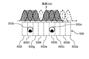
- FIG. 7A and 7B are diagrams showing light intensity distributions in the eyebox partial regions 600a to 600i.
- the intensity of light incident on each light source element 111a to 111i is maximized in the corresponding region of the eye box partial region 600a to 600i of the eye box 600, respectively. Since the light source elements 111a to 111i of the head-up display 100 according to the present embodiment are arranged densely, the light emitted from each of the light source elements 111a to 111i is not only the corresponding eye box partial area but also its adjacent area. It also enters the eyebox partial area.
- FIG. 7A is a diagram showing a light intensity distribution in the eye box 600 when the left eye 300a of the observer 300 is in the eye box partial area 600c and the right eye 300b of the observer 300 is in the eye box partial area 600g. .
- the light source element 111b, the light source element 111c, and the light source element 111d are turned on for the left eye 300a.
- the light source element 111f and the light source element 111h are turned on.
- the light emitted from the light source elements 111a, 111e, and 111i is turned off because it is not incident on the viewpoint position of the observer 300.
- FIG. 7B is a diagram showing a light intensity distribution in the eye box 600 when the observer 300 moves to the left side of the drawing from the state of FIG. 7A. Specifically, a case where the left eye 300a of the observer 300 moves from the eyebox partial area 600c to 600d and the right eye 300b of the observer 300 moves from the eyebox partial area 600g to 600h will be described. In this case, when the left eye 300a of the observer 300 enters the eyebox partial region 600d, the light source element 111e is turned on in addition to the light source elements 111c and 111d for the left eye 300a. Since the light emitted from the light source element 111b is not incident on the left eye 300a, it can be turned off.
- the light source element 111i is turned on in addition to the light source elements 111g and 111h.
- the light source element 111f in which the emitted light is not incident on the right eye 300b is turned off. That is, the light source elements 111a, 111b, and 111f can be turned off. Switching between turning off and turning on is performed by simultaneously controlling the light source element to be turned off and the light source element to be turned on, because the number of light source elements that illuminate the viewpoint position of the viewer 300 does not change. There is no effect on brightness.
- the light intensity distribution for each light source element 111 that is lit is indicated by a solid line. Further, the distribution of the light intensity incident on the eye box 600 is indicated by the hatched portion. That is, the shaded area is a combination of the light intensity distributions indicated by the solid lines. 7A and 7B, as can be seen from the position of the eye of the viewer 300 and the intensity distribution of the shaded area, it is possible to suppress a large change in light intensity around the eye of the viewer 300. Thereby, when the control of the light source element 111 has not completely followed the movement of the eye of the viewer 300, the change in the luminance of the virtual image 400 viewed from the viewer 300 can be suppressed.
- Embodiments 1 and 2 have been described as examples of the technology disclosed in the present application.
- the technology in the present disclosure is not limited to this, and can also be applied to embodiments that have been changed, replaced, added, omitted, and the like.
- the liquid crystal panel 115 is used as the spatial light modulation element, but other display elements can be used as long as they are transmissive display devices.
- liquid crystal panel 115 is arranged so as to be orthogonal to the chief ray of the light source element 111 is shown, it may be arranged not inclined but inclined.
- the focal length of the first lens 112 is changed from the optical center of the first lens 112. You may set to the value more than the distance to the output surface 113b of the 2nd lens 113. FIG. This also makes it possible to generate a virtual image with reduced luminance unevenness.
- one first lens 112 is arranged for a plurality of light source elements 111, but a plurality of first lenses may be arranged for a plurality of light source elements 111.
- the first lens 112 is a convex lens, but a TIR (Total Internal Reflection) lens can also be used. Thereby, the light from the light source element 111 can be efficiently emitted to the second lens 113, and the light utilization efficiency is improved.
- TIR Total Internal Reflection
- the illumination device 110 only one row of light source elements 111 is arranged in the Y-axis direction (the width direction of the liquid crystal panel 115). However, a plurality of light source elements 111 are arranged in the Y-axis direction. Also good.
- the diffusion plate 114 is disposed between the second lens 113 and the liquid crystal panel 115, but the diffusion plate 114 may be disposed between the first lens 112 and the second lens 113. Although inferior in efficiency, luminance unevenness can be reduced even at this position.
- the windshield 230 is exemplified as a member for reflecting the light emitted from the head-up display 100, the present invention is not limited thereto, and a combiner can also be used.
- the LED is exemplified as the light source, a laser diode, an organic light emitting diode, or the like can also be used.
- the head-up display that observes with both eyes has been described as a light source control method, but a head-up display that observes with a single eye can also be realized by controlling in the same manner as described above.
- a conventional monocular head-up display device light may be emitted to both eyes depending on the position of the observer's eyes, and a virtual image may be visually recognized with both eyes, but control is performed as in the present embodiment. Therefore, it becomes easy to irradiate only to a single eye.
- the viewpoint detection unit 800 may not only directly detect the position of the eye, but also may estimate from the eyebrows, the nose, and the contour of the face.
- power saving is achieved by control by turning on and off according to the position of the eyes of the observer, but the light source element 111 may be moved according to the position of the eyes of the observer 300. .
- the light source element that does not reach the eyes of the observer 300 is exemplified to be extinguished.
- the light intensity of the light source element 111 may be turned on and lighted. Thereby, when the eye is positioned at the boundary position of the eyebox partial area, the luminance unevenness can be reduced.
- the display image of the liquid crystal panel 115 can be time-divided to present different images to the left and right eyes for stereoscopic viewing.
- the light source element when displaying an image for the right eye, the light source element is turned on and off so as to illuminate only the eye box partial area where the right eye is located.
- autostereoscopic display is possible.
- the moving body on which the head-up display 100 according to the present embodiment is mounted is not limited to an automobile vehicle, and includes various devices that transport railway vehicles, motorcycles, aircraft, helicopters, ships, and other people.
- the present disclosure can be applied to a projection device that visually recognizes a virtual image. Specifically, the present disclosure is applicable to a head-up display.
- DESCRIPTION OF SYMBOLS 100 Head-up display 110 Illuminating device 111 Light source element 112 1st lens 112a Incident surface 112a (1st lens) Output surface 113b 2nd lens 113a (2nd lens) Incident surface 113b (2nd lens) Outgoing surface 114 Diffusion plate (Diffusion member) 115 liquid crystal panel 115a incident surface (liquid crystal panel) incident surface 115b (liquid crystal panel) output surface 120 display unit 130 reflective optical unit 131 first mirror 132 second mirror 140 housing 141 opening 200 vehicle 230 windshield 300 observer 300a left eye 300b Right eye 400 Virtual image 500 Virtual image optical system 600 Eye box 700 Control unit
Landscapes
- Engineering & Computer Science (AREA)
- Physics & Mathematics (AREA)
- General Physics & Mathematics (AREA)
- Theoretical Computer Science (AREA)
- Combustion & Propulsion (AREA)
- Mechanical Engineering (AREA)
- Transportation (AREA)
- Chemical & Material Sciences (AREA)
- Optics & Photonics (AREA)
- Computer Hardware Design (AREA)
- General Engineering & Computer Science (AREA)
- Human Computer Interaction (AREA)
- Instrument Panels (AREA)
- Liquid Crystal (AREA)
- Liquid Crystal Display Device Control (AREA)
- Control Of Indicators Other Than Cathode Ray Tubes (AREA)
- Controls And Circuits For Display Device (AREA)
Abstract
L'invention concerne un affichage tête haute qui projette une image sur un boîtier oculaire d'observateur. L'affichage tête haute comprend une pluralité d'éléments de source de lumière, un panneau à cristaux liquides (115), une première lentille (112), une unité de détection de point de vue (800) et une unité de commande (700). La pluralité d'éléments de source de lumière sont agencés sous forme d'un réseau, et émettent de la lumière. Dans le panneau à cristaux liquides (115), la première lentille (112), qui affiche l'image, dévie la lumière émise à partir de la pluralité d'éléments de source de lumière de façon à éclairer la même région dans une surface incidente du panneau à cristaux liquides (115). L'unité de détection de point de vue (800) détecte une position de point de vue de l'observateur. L'unité de commande (700) commande l'intensité de la lumière des éléments de la source de lumière en fonction de la position de point de vue détectée par l'unité de détection de point de vue (800).
Priority Applications (3)
| Application Number | Priority Date | Filing Date | Title |
|---|---|---|---|
| EP16817455.5A EP3287834B1 (fr) | 2015-07-01 | 2016-06-24 | Affichage tête haute et corps mobile le comprenant |
| JP2017526172A JP6586646B2 (ja) | 2015-07-01 | 2016-06-24 | ヘッドアップディスプレイ及びヘッドアップディスプレイを備えた移動体 |
| US15/839,489 US10302943B2 (en) | 2015-07-01 | 2017-12-12 | Head-up display and moving body comprising head-up display |
Applications Claiming Priority (2)
| Application Number | Priority Date | Filing Date | Title |
|---|---|---|---|
| JP2015132282 | 2015-07-01 | ||
| JP2015-132282 | 2015-07-01 |
Related Child Applications (1)
| Application Number | Title | Priority Date | Filing Date |
|---|---|---|---|
| US15/839,489 Continuation US10302943B2 (en) | 2015-07-01 | 2017-12-12 | Head-up display and moving body comprising head-up display |
Publications (1)
| Publication Number | Publication Date |
|---|---|
| WO2017002344A1 true WO2017002344A1 (fr) | 2017-01-05 |
Family
ID=57608187
Family Applications (1)
| Application Number | Title | Priority Date | Filing Date |
|---|---|---|---|
| PCT/JP2016/003053 Ceased WO2017002344A1 (fr) | 2015-07-01 | 2016-06-24 | Affichage tête haute et corps mobile le comprenant |
Country Status (4)
| Country | Link |
|---|---|
| US (1) | US10302943B2 (fr) |
| EP (1) | EP3287834B1 (fr) |
| JP (1) | JP6586646B2 (fr) |
| WO (1) | WO2017002344A1 (fr) |
Cited By (14)
| Publication number | Priority date | Publication date | Assignee | Title |
|---|---|---|---|---|
| JP2020112667A (ja) * | 2019-01-10 | 2020-07-27 | 株式会社デンソー | 虚像表示装置 |
| EP3696594A1 (fr) | 2019-01-07 | 2020-08-19 | Yazaki Corporation | Dispositif d'affichage tête haute |
| WO2021059952A1 (fr) * | 2019-09-24 | 2021-04-01 | 日本精機株式会社 | Dispositif d'affichage tête haute |
| JP2021060564A (ja) * | 2019-10-09 | 2021-04-15 | 株式会社デンソー | 虚像表示装置及び表示制御装置 |
| JP2021084466A (ja) * | 2019-11-26 | 2021-06-03 | 矢崎総業株式会社 | 車両表示装置 |
| JPWO2021193636A1 (fr) * | 2020-03-25 | 2021-09-30 | ||
| JP2022026522A (ja) * | 2020-07-31 | 2022-02-10 | 日本精機株式会社 | ヘッドアップディスプレイ装置 |
| JP2022026716A (ja) * | 2020-07-31 | 2022-02-10 | 日本精機株式会社 | ヘッドアップディスプレイ装置 |
| JP2022036431A (ja) * | 2020-08-24 | 2022-03-08 | 日本精機株式会社 | ヘッドアップディスプレイ装置、表示制御装置、及びヘッドアップディスプレイ装置の制御方法 |
| JP2022040442A (ja) * | 2020-08-31 | 2022-03-11 | 日本精機株式会社 | 表示制御装置、ヘッドアップディスプレイ装置 |
| JP2022085399A (ja) * | 2020-11-27 | 2022-06-08 | 日本精機株式会社 | 表示制御装置、ヘッドアップディスプレイ装置及び、表示制御方法 |
| JP2022533160A (ja) * | 2019-05-17 | 2022-07-21 | フューチュラス テクノロジー カンパニー リミテッド | 光制御装置、パッシブ発光型画像ソース及びヘッドアップディスプレイシステム |
| JP2022171105A (ja) * | 2021-04-30 | 2022-11-11 | 日本精機株式会社 | 表示制御装置、ヘッドアップディスプレイ装置及び、表示制御方法 |
| JP2022181938A (ja) * | 2021-05-27 | 2022-12-08 | 日本精機株式会社 | ヘッドアップディスプレイ装置 |
Families Citing this family (15)
| Publication number | Priority date | Publication date | Assignee | Title |
|---|---|---|---|---|
| US11126005B2 (en) * | 2016-10-24 | 2021-09-21 | Maxell, Ltd. | Head up display system for expanding a display range of a virtual image |
| US10762810B2 (en) * | 2018-01-05 | 2020-09-01 | North Inc. | Augmented reality eyebox fitting optimization for individuals |
| JP7117578B2 (ja) * | 2018-03-20 | 2022-08-15 | パナソニックIpマネジメント株式会社 | ヘッドアップディスプレイ及び移動体 |
| FR3083331B1 (fr) * | 2018-06-29 | 2021-09-03 | Faurecia Interieur Ind | Dispositif de realite augmentee pour vehicule |
| US10884249B2 (en) * | 2018-10-23 | 2021-01-05 | Panasonic Automotive Systems Company Of America, Division Of Panasonic Corporation Of North America | Combiner head up display with separate infrared function |
| CN109849791B (zh) * | 2019-03-07 | 2021-04-13 | 宁波吉利汽车研究开发有限公司 | 一种辅助驾驶系统及车辆 |
| CN112622767A (zh) | 2019-10-08 | 2021-04-09 | 松下知识产权经营株式会社 | 显示系统、以及具备该显示系统的电子后视镜系统 |
| US11960080B2 (en) * | 2020-10-20 | 2024-04-16 | Nippon Seiki Co., Ltd. | Head-up display device |
| FR3125895B1 (fr) * | 2021-07-30 | 2026-04-17 | Valeo Comfort & Driving Assistance | Dispositif de génération d’images et afficheur tête haute comportant un tel dispositif |
| DE102021213836A1 (de) * | 2021-12-06 | 2023-06-07 | Continental Automotive Technologies GmbH | Verfahren, Computerprogramm und Vorrichtung zum Steuern einer bildgebenden Einheit einer Anzeigevorrichtung, sowie Anzeigevorrichtung |
| KR102730251B1 (ko) * | 2022-02-16 | 2024-11-13 | 현대모비스 주식회사 | 헤드업 디스플레이 장치 및 그 제어방법 |
| KR20230123200A (ko) * | 2022-02-16 | 2023-08-23 | 현대모비스 주식회사 | 헤드업 디스플레이 장치 및 그 제어방법 |
| TWI830146B (zh) * | 2022-02-16 | 2024-01-21 | 友達光電股份有限公司 | 裸眼式立體顯示系統及其顯示方法 |
| US12159560B2 (en) | 2023-03-22 | 2024-12-03 | Ford Global Technologies, Llc | Projector power management for head-up displays |
| US12472815B2 (en) * | 2023-07-12 | 2025-11-18 | Infineon Technologies Austria Ag | Driver and passenger aware content projection |
Citations (5)
| Publication number | Priority date | Publication date | Assignee | Title |
|---|---|---|---|---|
| JPH08211325A (ja) * | 1995-02-06 | 1996-08-20 | Olympus Optical Co Ltd | 映像表示装置 |
| JP2003039981A (ja) * | 2001-07-26 | 2003-02-13 | Yazaki Corp | 車載用ヘッドアップディスプレイ装置 |
| JP2010197493A (ja) * | 2009-02-23 | 2010-09-09 | Nippon Sheet Glass Co Ltd | ヘッドアップディスプレイ |
| JP2015087698A (ja) * | 2013-11-01 | 2015-05-07 | Necプラットフォームズ株式会社 | 虚像表示装置 |
| JP2015099186A (ja) * | 2013-11-18 | 2015-05-28 | 三菱電機株式会社 | 車両用表示装置 |
Family Cites Families (9)
| Publication number | Priority date | Publication date | Assignee | Title |
|---|---|---|---|---|
| US5714967A (en) * | 1994-05-16 | 1998-02-03 | Olympus Optical Co., Ltd. | Head-mounted or face-mounted image display apparatus with an increased exit pupil |
| JP3717654B2 (ja) | 1998-02-17 | 2005-11-16 | 株式会社リコー | カラー画像表示装置 |
| JP4686462B2 (ja) | 2003-09-30 | 2011-05-25 | コーニンクレッカ フィリップス エレクトロニクス エヌ ヴィ | 液晶ディスプレイアプリケーション用光源アレイ |
| JP2007108429A (ja) | 2005-10-13 | 2007-04-26 | Denso Corp | 表示装置とそれを備えた車両用ヘッドアップディスプレイ装置 |
| US7542210B2 (en) * | 2006-06-29 | 2009-06-02 | Chirieleison Sr Anthony | Eye tracking head mounted display |
| JP2011059270A (ja) * | 2009-09-08 | 2011-03-24 | Nippon Seiki Co Ltd | 車両用表示装置 |
| KR101408501B1 (ko) | 2010-01-12 | 2014-06-17 | 가부시키가이샤 니콘 | 표시 장치 및 표시 방법 |
| JP5463939B2 (ja) | 2010-02-01 | 2014-04-09 | 株式会社ニコン | 表示装置および表示方法 |
| US9097890B2 (en) * | 2010-02-28 | 2015-08-04 | Microsoft Technology Licensing, Llc | Grating in a light transmissive illumination system for see-through near-eye display glasses |
-
2016
- 2016-06-24 WO PCT/JP2016/003053 patent/WO2017002344A1/fr not_active Ceased
- 2016-06-24 JP JP2017526172A patent/JP6586646B2/ja active Active
- 2016-06-24 EP EP16817455.5A patent/EP3287834B1/fr active Active
-
2017
- 2017-12-12 US US15/839,489 patent/US10302943B2/en active Active
Patent Citations (5)
| Publication number | Priority date | Publication date | Assignee | Title |
|---|---|---|---|---|
| JPH08211325A (ja) * | 1995-02-06 | 1996-08-20 | Olympus Optical Co Ltd | 映像表示装置 |
| JP2003039981A (ja) * | 2001-07-26 | 2003-02-13 | Yazaki Corp | 車載用ヘッドアップディスプレイ装置 |
| JP2010197493A (ja) * | 2009-02-23 | 2010-09-09 | Nippon Sheet Glass Co Ltd | ヘッドアップディスプレイ |
| JP2015087698A (ja) * | 2013-11-01 | 2015-05-07 | Necプラットフォームズ株式会社 | 虚像表示装置 |
| JP2015099186A (ja) * | 2013-11-18 | 2015-05-28 | 三菱電機株式会社 | 車両用表示装置 |
Cited By (26)
| Publication number | Priority date | Publication date | Assignee | Title |
|---|---|---|---|---|
| EP3696594A1 (fr) | 2019-01-07 | 2020-08-19 | Yazaki Corporation | Dispositif d'affichage tête haute |
| JP2020112667A (ja) * | 2019-01-10 | 2020-07-27 | 株式会社デンソー | 虚像表示装置 |
| JP7131397B2 (ja) | 2019-01-10 | 2022-09-06 | 株式会社デンソー | 虚像表示装置 |
| US12320974B2 (en) | 2019-05-17 | 2025-06-03 | Futurus Technology Co., Ltd. | Light control apparatus, passive light-emitting image source and head-up display system |
| JP2022533160A (ja) * | 2019-05-17 | 2022-07-21 | フューチュラス テクノロジー カンパニー リミテッド | 光制御装置、パッシブ発光型画像ソース及びヘッドアップディスプレイシステム |
| WO2021059952A1 (fr) * | 2019-09-24 | 2021-04-01 | 日本精機株式会社 | Dispositif d'affichage tête haute |
| JPWO2021059952A1 (fr) * | 2019-09-24 | 2021-04-01 | ||
| JP7509150B2 (ja) | 2019-09-24 | 2024-07-02 | 日本精機株式会社 | ヘッドアップディスプレイ |
| JP2021060564A (ja) * | 2019-10-09 | 2021-04-15 | 株式会社デンソー | 虚像表示装置及び表示制御装置 |
| JP7276062B2 (ja) | 2019-10-09 | 2023-05-18 | 株式会社デンソー | 虚像表示装置及び表示制御装置 |
| JP2021084466A (ja) * | 2019-11-26 | 2021-06-03 | 矢崎総業株式会社 | 車両表示装置 |
| JP7584001B2 (ja) | 2020-03-25 | 2024-11-15 | 日本精機株式会社 | ヘッドアップディスプレイ装置、表示制御装置、及び表示制御方法 |
| WO2021193636A1 (fr) * | 2020-03-25 | 2021-09-30 | 日本精機株式会社 | Dispositif d'affichage tête haute, dispositif de commande d'affichage et procédé de commande d'affichage |
| JPWO2021193636A1 (fr) * | 2020-03-25 | 2021-09-30 | ||
| JP2022026716A (ja) * | 2020-07-31 | 2022-02-10 | 日本精機株式会社 | ヘッドアップディスプレイ装置 |
| JP2022026522A (ja) * | 2020-07-31 | 2022-02-10 | 日本精機株式会社 | ヘッドアップディスプレイ装置 |
| JP7494646B2 (ja) | 2020-08-24 | 2024-06-04 | 日本精機株式会社 | ヘッドアップディスプレイ装置、表示制御装置、及びヘッドアップディスプレイ装置の制御方法 |
| JP2022036431A (ja) * | 2020-08-24 | 2022-03-08 | 日本精機株式会社 | ヘッドアップディスプレイ装置、表示制御装置、及びヘッドアップディスプレイ装置の制御方法 |
| JP7569497B2 (ja) | 2020-08-31 | 2024-10-18 | 日本精機株式会社 | 表示制御装置、ヘッドアップディスプレイ装置 |
| JP2022040442A (ja) * | 2020-08-31 | 2022-03-11 | 日本精機株式会社 | 表示制御装置、ヘッドアップディスプレイ装置 |
| JP2022085399A (ja) * | 2020-11-27 | 2022-06-08 | 日本精機株式会社 | 表示制御装置、ヘッドアップディスプレイ装置及び、表示制御方法 |
| JP7579504B2 (ja) | 2020-11-27 | 2024-11-08 | 日本精機株式会社 | 表示制御装置、ヘッドアップディスプレイ装置及び、表示制御方法 |
| JP2022171105A (ja) * | 2021-04-30 | 2022-11-11 | 日本精機株式会社 | 表示制御装置、ヘッドアップディスプレイ装置及び、表示制御方法 |
| JP7661769B2 (ja) | 2021-04-30 | 2025-04-15 | 日本精機株式会社 | 表示制御装置、ヘッドアップディスプレイ装置及び、表示制御方法 |
| JP2022181938A (ja) * | 2021-05-27 | 2022-12-08 | 日本精機株式会社 | ヘッドアップディスプレイ装置 |
| JP7661790B2 (ja) | 2021-05-27 | 2025-04-15 | 日本精機株式会社 | ヘッドアップディスプレイ装置 |
Also Published As
| Publication number | Publication date |
|---|---|
| JPWO2017002344A1 (ja) | 2018-05-24 |
| US10302943B2 (en) | 2019-05-28 |
| EP3287834B1 (fr) | 2019-08-07 |
| EP3287834A1 (fr) | 2018-02-28 |
| JP6586646B2 (ja) | 2019-10-09 |
| EP3287834A4 (fr) | 2018-03-14 |
| US20180101007A1 (en) | 2018-04-12 |
Similar Documents
| Publication | Publication Date | Title |
|---|---|---|
| JP6586646B2 (ja) | ヘッドアップディスプレイ及びヘッドアップディスプレイを備えた移動体 | |
| JP5866644B1 (ja) | ヘッドアップディスプレイ及びヘッドアップディスプレイを備えた移動体 | |
| JP6078798B2 (ja) | ヘッドアップディスプレイ、照明装置およびそれを備えた移動体 | |
| JP6098375B2 (ja) | ヘッドアップディスプレイ装置 | |
| JP6823817B2 (ja) | ヘッドアップディスプレイ装置 | |
| US9004691B2 (en) | Head-up display device using a concave cylindrical lens for projecting image on screen | |
| EP3093708B1 (fr) | Écran transmetteur et dispositif d'affichage d'image l'utilisant | |
| JP7117578B2 (ja) | ヘッドアップディスプレイ及び移動体 | |
| JP6663890B2 (ja) | バックライトユニットおよびヘッドアップディスプレイ装置 | |
| US20140085570A1 (en) | Backlight and liquid crystal display device | |
| CN109946838B (zh) | 平视显示器装置 | |
| WO2014119407A1 (fr) | Dispositif d'affichage tête haute | |
| JP2018018706A (ja) | 照明装置およびヘッドアップディスプレイ装置 | |
| JPWO2017131185A1 (ja) | 車両用ヘッドアップディスプレイ装置 | |
| US20250147399A1 (en) | Optical member, light source device, and head-up display | |
| US20240192512A1 (en) | Directional optical devices | |
| JP2022160993A (ja) | 車両用表示装置 |
Legal Events
| Date | Code | Title | Description |
|---|---|---|---|
| 121 | Ep: the epo has been informed by wipo that ep was designated in this application |
Ref document number: 16817455 Country of ref document: EP Kind code of ref document: A1 |
|
| WWE | Wipo information: entry into national phase |
Ref document number: 2016817455 Country of ref document: EP |
|
| ENP | Entry into the national phase |
Ref document number: 2017526172 Country of ref document: JP Kind code of ref document: A |
|
| NENP | Non-entry into the national phase |
Ref country code: DE |