WO2017002389A1 - 超伝導加速器 - Google Patents
超伝導加速器 Download PDFInfo
- Publication number
- WO2017002389A1 WO2017002389A1 PCT/JP2016/054710 JP2016054710W WO2017002389A1 WO 2017002389 A1 WO2017002389 A1 WO 2017002389A1 JP 2016054710 W JP2016054710 W JP 2016054710W WO 2017002389 A1 WO2017002389 A1 WO 2017002389A1
- Authority
- WO
- WIPO (PCT)
- Prior art keywords
- refrigerant tank
- outer peripheral
- acceleration cavity
- superconducting
- superconducting accelerator
- Prior art date
- Legal status (The legal status is an assumption and is not a legal conclusion. Google has not performed a legal analysis and makes no representation as to the accuracy of the status listed.)
- Ceased
Links
Images





Classifications
-
- H—ELECTRICITY
- H05—ELECTRIC TECHNIQUES NOT OTHERWISE PROVIDED FOR
- H05H—PLASMA TECHNIQUE; PRODUCTION OF ACCELERATED ELECTRICALLY-CHARGED PARTICLES OR OF NEUTRONS; PRODUCTION OR ACCELERATION OF NEUTRAL MOLECULAR OR ATOMIC BEAMS
- H05H9/00—Linear accelerators
-
- H—ELECTRICITY
- H05—ELECTRIC TECHNIQUES NOT OTHERWISE PROVIDED FOR
- H05H—PLASMA TECHNIQUE; PRODUCTION OF ACCELERATED ELECTRICALLY-CHARGED PARTICLES OR OF NEUTRONS; PRODUCTION OR ACCELERATION OF NEUTRAL MOLECULAR OR ATOMIC BEAMS
- H05H7/00—Details of devices of the types covered by groups H05H9/00, H05H11/00, H05H13/00
- H05H7/14—Vacuum chambers
- H05H7/18—Cavities; Resonators
- H05H7/20—Cavities; Resonators with superconductive walls
-
- H—ELECTRICITY
- H05—ELECTRIC TECHNIQUES NOT OTHERWISE PROVIDED FOR
- H05H—PLASMA TECHNIQUE; PRODUCTION OF ACCELERATED ELECTRICALLY-CHARGED PARTICLES OR OF NEUTRONS; PRODUCTION OR ACCELERATION OF NEUTRAL MOLECULAR OR ATOMIC BEAMS
- H05H7/00—Details of devices of the types covered by groups H05H9/00, H05H11/00, H05H13/00
- H05H7/22—Details of linear accelerators, e.g. drift tubes
-
- H—ELECTRICITY
- H05—ELECTRIC TECHNIQUES NOT OTHERWISE PROVIDED FOR
- H05H—PLASMA TECHNIQUE; PRODUCTION OF ACCELERATED ELECTRICALLY-CHARGED PARTICLES OR OF NEUTRONS; PRODUCTION OR ACCELERATION OF NEUTRAL MOLECULAR OR ATOMIC BEAMS
- H05H7/00—Details of devices of the types covered by groups H05H9/00, H05H11/00, H05H13/00
- H05H7/22—Details of linear accelerators, e.g. drift tubes
- H05H2007/222—Details of linear accelerators, e.g. drift tubes drift tubes
-
- H—ELECTRICITY
- H05—ELECTRIC TECHNIQUES NOT OTHERWISE PROVIDED FOR
- H05H—PLASMA TECHNIQUE; PRODUCTION OF ACCELERATED ELECTRICALLY-CHARGED PARTICLES OR OF NEUTRONS; PRODUCTION OR ACCELERATION OF NEUTRAL MOLECULAR OR ATOMIC BEAMS
- H05H9/00—Linear accelerators
- H05H9/04—Standing-wave linear accelerators
- H05H9/041—Hadron LINACS
-
- H—ELECTRICITY
- H05—ELECTRIC TECHNIQUES NOT OTHERWISE PROVIDED FOR
- H05H—PLASMA TECHNIQUE; PRODUCTION OF ACCELERATED ELECTRICALLY-CHARGED PARTICLES OR OF NEUTRONS; PRODUCTION OR ACCELERATION OF NEUTRAL MOLECULAR OR ATOMIC BEAMS
- H05H9/00—Linear accelerators
- H05H9/04—Standing-wave linear accelerators
- H05H9/048—Lepton LINACS
Definitions
- the present invention relates to a superconducting accelerator.
- the present application claims priority based on Japanese Patent Application No. 2015-131089 filed in Japan on June 30, 2015, the contents of which are incorporated herein by reference.
- a superconducting accelerator that accelerates charged particles such as electrons and protons using a superconducting acceleration cavity is known.
- the superconducting accelerator makes a superconducting acceleration cavity formed of a superconducting material superconducting by cooling with a refrigerant such as liquid helium. As a result, the electrical resistance of the superconducting acceleration cavity becomes almost zero, and the charged particles can be accelerated efficiently without power loss.
- the resonance frequency of the superconducting acceleration cavity is adjusted by adjusting the length of the gap that forms the high-frequency electric field that accelerates charged particles in the superconducting acceleration cavity.
- Patent Document 1 discloses a configuration in which the axial length of a refrigerant tank that accommodates a superconducting acceleration cavity is adjusted by expanding and contracting the distance between two flanges provided in the refrigerant tank.
- a wedge-shaped nut having a tapered surface is provided between the seat plates in close contact with each of the two flanges, and the nut is moved along the surface of the seat plate by a bolt. Adjust the distance between the plates.
- Beam members longer than the diameter of the refrigerant tank are provided on both sides of the superconducting acceleration cavity in the radial direction of the refrigerant tank, and both ends of the beam members are connected to each other on both sides in the radial direction of the refrigerant tank by screw members or the like.
- a resonance frequency adjustment method has also been proposed. According to this configuration, by increasing or decreasing the distance between the beam members with the screw member, the superconducting acceleration cavity can be deformed to change the length of the particle passage, and the resonance frequency of the superconducting acceleration cavity can be adjusted.
- the above-described resonance frequency adjustment method varies the axial length of the entire refrigerant tank by moving a wedge-shaped nut provided between two seat plates along the surface of the seat plate. Therefore, a large force acts on the seat plate and the nut. Therefore, the seat plate and the nut must be strong. This increases the size of the seat plate and nut, leading to higher cost and larger size of the superconducting accelerator. When other devices are provided around the seat plate and the nut, the layout must be made so that the seat plate and the nut do not interfere with other devices, which takes time.
- the superconducting accelerator is increased in cost, size, and other equipment. This leads to an increase in labor for layout work to avoid interference.
- the present invention provides a superconducting accelerator capable of surely adjusting the resonance frequency of a superconducting acceleration cavity and reducing the cost, downsizing the superconducting accelerator, and reducing the labor of layout work. With the goal.
- the superconducting accelerator is disposed on the outer peripheral side of the acceleration cavity and an acceleration cavity that forms a space for accelerating the charged particle beam in the superconducting state, and is disposed in the gap between the acceleration cavity.
- the superconducting accelerator is provided at the outer periphery of the refrigerant tank, and is provided at each end of the acceleration cavity in the beam axis direction of the charged particle beam, or at both ends in the direction perpendicular to the beam axis direction.
- the pressing member is further provided.
- the superconducting accelerator is provided continuously on the outer periphery of the refrigerant tank, and generates a tension member in a direction in which the pair of pressing members are brought close to each other, and a tension member that adjusts the tension generated by the tension member. And an adjustment unit.
- the pressing member may be provided at least at a portion that presses the acceleration cavity while minimizing the dimension protruding laterally from the acceleration cavity. Therefore, it can suppress that the member which adjusts a resonant frequency protrudes greatly to the outer peripheral side of an acceleration cavity or a refrigerant tank.
- the tension member according to the first aspect is a wire, and a plurality of the wires are hooked around the outer peripheral portion of the refrigerant tank in a circumferential direction. You may make it provide the pulley of this.
- a wire can be provided along the outer peripheral part of a refrigerant tank, without interfering with a refrigerant tank by latching to the several pulley provided in the outer peripheral part of a refrigerant tank.
- the superconducting accelerator projects from the outer peripheral part of the refrigerant tank to the outer peripheral side on the outer peripheral part of the refrigerant tank of the second aspect, and the support convex part that rotatably supports the pulley. May be provided.
- a pulley can be provided in the outer peripheral side of a refrigerant tank.
- a wire can be continuously arrange
- the support convex portion is formed continuously in the circumferential direction along the outer peripheral portion of the refrigerant tank. Also good. By comprising in this way, the intensity
- the push member in the superconducting accelerator according to any one of the second to fourth aspects, may be provided with the pulley.
- tensile_strength of a tension member acts directly on the press member arrange
- the acceleration cavity can be efficiently pressed by the pressing member.
- the pressing member may be provided so as to hit only the pressing portion of the acceleration cavity, and the pressing member can be reduced in size.
- the superconducting accelerator is disposed on the outer peripheral side of the acceleration cavity and the acceleration cavity that forms a space for accelerating the charged particle beam in the superconducting state, and is disposed in the gap between the acceleration cavity.
- Superconducting accelerators are provided on the outer periphery of the refrigerant tank, and are arranged at both ends in the beam axis direction of the charged particle beam in the acceleration cavity, or both ends in the direction perpendicular to the beam axis direction, respectively.
- the apparatus further includes a pair of arms that are swingably supported around a support shaft provided on the outer peripheral portion of the refrigerant tank, and that have a first end portion that faces the end portion.
- the superconducting accelerator further includes an arm displacement portion that presses the end portion with the first end portion of the arm by displacing the second end portions of the pair of arms in a direction in which the second end portions are separated from each other.
- both ends in the beam axis direction of the charged particle beam in the acceleration cavity, or both ends in the direction perpendicular to the beam axis direction are pressed, and the acceleration cavity is deformed to change the length of the particle flow path of the charged particles.
- the resonance frequency of the acceleration cavity can be adjusted. Since the mechanism for adjusting the resonance frequency of the acceleration cavity includes the arm, the support shaft, and the arm displacement portion, a simple configuration is sufficient. Furthermore, the arm may be provided at a portion that presses the acceleration cavity along the outer peripheral portion of the refrigerant tank, and the member that adjusts the resonance frequency can be prevented from greatly projecting to the outer peripheral side of the acceleration cavity or the refrigerant tank. it can.
- the arms are arranged at both ends in the beam axis direction of the charged particle beam in the acceleration cavity or in a direction perpendicular to the beam axis direction. You may make it extend to the both sides of the circumferential direction of the said refrigerant
- the superconducting accelerator projects to the outer peripheral portion of the refrigerant tank from the outer peripheral portion of the refrigerant tank and supports the support shaft.
- a convex portion may be provided.
- the support convex portion is formed continuously in the circumferential direction along the outer peripheral portion of the refrigerant tank. Good. By comprising in this way, the intensity
- the resonance frequency of the superconducting acceleration cavity can be adjusted reliably, and the cost can be reduced, the superconducting accelerator can be downsized, and the layout work can be reduced.
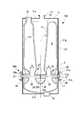
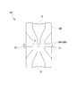
- FIG. 1 is an elevational sectional view showing the configuration of the superconducting accelerator of this embodiment.
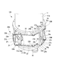
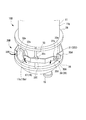
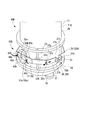
- FIG. 2 is a perspective view showing a resonance frequency adjusting mechanism provided in the superconducting accelerator.
- FIG. 3 is a plan sectional view of the resonance frequency adjusting mechanism.
- the superconducting accelerator 10A of this embodiment is, for example, a coaxial quarter wavelength superconducting accelerator (QWR: Quarter Wave Resonator).
- QWR Quarter Wave Resonator
- the refrigerant tank 11 is a cylindrical vacuum container having a central axis C extending in the vertical direction, and the upper end surface 11a and the lower end surface 11b are closed.
- the refrigerant tank 11 may include a shield layer that reduces the influence of external geomagnetism and radiant heat.
- the acceleration cavity 12 is formed of a superconducting material such as niobium and has a hollow chamber shape continuous in the vertical direction.
- a gap S is formed between the acceleration cavity 12 and the inner peripheral surface 11 f of the refrigerant tank 11.
- the acceleration cavity 12 includes a beam introduction tube 17 and a beam extraction tube 18 having a circular cross section at the lower part of the outer peripheral surface 12f.
- the beam introduction pipe 17 and the beam lead-out pipe 18 are provided at positions facing each other in the radial direction orthogonal to the central axis C of the refrigerant tank 11.
- the beam introduction tube 17 and the beam lead-out tube 18 respectively extend outward in the radial direction from the outer peripheral surface 12 f of the acceleration cavity 12, pass through the refrigerant tank 11, and protrude outward in the radial direction of the refrigerant tank 11.
- the acceleration cavity 12 includes a stem 13 formed so as to extend in the vertical direction along the central axis C of the refrigerant tank 11.
- the stem 13 is recessed downward from the upper end portion of the acceleration cavity 12, and the inner diameter thereof gradually decreases from the upper side to the lower side.
- an annular flow path 13 c formed in an annular shape continuously with the stem 13 is integrally formed.
- a beam flow tube portion 19 is formed on the inner side of the annular flow path 13c so as to be coaxial with the beam introduction tube 17 and the beam discharge tube 18 of the acceleration cavity 12.
- the acceleration cavity 12 includes a connection port 15 that penetrates through the upper end surface 11a of the refrigerant tank 11 and communicates with the hollow acceleration cavity 12 at the upper end thereof.
- the inside of the acceleration cavity 12 can be evacuated by evacuating the connection port 15 with a vacuum pump or the like.
- the acceleration cavity 12 has an input coupling portion 16 at the lower end thereof. By inputting high frequency power from the input coupling unit 16, an electric field for accelerating the charged particle beam B is generated in the space A in the acceleration cavity 12.
- the refrigerant tank 11 includes a refrigerant supply port 14 that is formed on the upper end surface 11 a and supplies the refrigerant into the refrigerant tank 11.
- the refrigerant sent from the refrigerant supply port 14 is sent into the gap S between the inner peripheral surface 11 f of the refrigerant tank 11 and the outer peripheral surface 12 f of the acceleration cavity 12, and into the stem 13 and the annular flow path 13 c.
- liquid helium or the like can be used as the refrigerant.
- the accelerating cavity 12 is cooled by the refrigerant sent into the refrigerant tank 11 to be in a superconducting state.
- the charged particle beam B enters the acceleration cavity 12 from the beam introduction tube 17 provided on the first side in the radial direction of the acceleration cavity 12, and enters the inside of the annular flow path 13 c provided at the lower end portion of the stem 13. It passes through the formed beam flow tube portion 19 and is sent out of the acceleration cavity 12 from a beam outlet tube 18 provided on the second side in the radial direction of the acceleration cavity 12.
- a plurality of such superconducting accelerators 10A are connected along the particle flow path of the charged particle beam B.
- the superconducting accelerators 10A adjacent to each other include a beam introducing tube 17 formed in the accelerating cavity 12 of one superconducting accelerator 10A and a beam derivation tube 18 formed in the accelerating cavity 12 of the other superconducting accelerator 10A. And are connected via a connecting pipe (not shown) or the like.
- a flange portion 26 is formed on the outer peripheral surface 11 g of the refrigerant tank 11.
- the flange portion 26 is formed above and below the end portion 17a of the beam introduction tube 17 and the end portion 18a of the beam outlet tube 18, respectively.
- These flange portions 26 are formed so as to protrude outward in the radial direction from the outer peripheral surface 11 g of the refrigerant tank 11.
- the flange portion 26 is formed in an annular shape that is continuous in the circumferential direction along the outer peripheral surface 11 g of the refrigerant tank 11.
- Each superconducting accelerator 10A includes a resonance frequency adjusting mechanism 20A.
- the resonance frequency adjustment mechanism 20A adjusts the resonance frequency of the acceleration cavity 12 by adjusting the distance between the end portion 17a of the beam introduction tube 17 and the end portion 18a of the beam extraction tube 18, and hence the beam acceleration gap G.
- the resonance frequency adjusting mechanism 20 ⁇ / b> A includes a pressing member 21, a wire (tension member) 22, pulleys 23 ⁇ / b> A and 23 ⁇ / b> B, and a tension adjusting unit 25.
- the pressing members 21 are provided at positions that face each other in the radial direction of the refrigerant tank 11 in the outer peripheral portion of the refrigerant tank 11. In other words, the pressing member 21 is provided as a pair of two at symmetrical positions with the refrigerant tank 11 in between. In this embodiment, the pressing member 21 is positioned between two upper and lower flange portions (supporting convex portions) 26 and abuts on the end portion 17 a of the beam introducing tube 17 and the end portion 18 a of the beam outlet tube 18.
- the pressing member 21 has a rectangular plate shape, an opening 21h communicating with the beam introduction tube 17 and the beam outlet tube 18 is formed at the center, and is divided into two in the circumferential direction of the refrigerant tank 11 around the opening 21h.
- the height of the pressing member 21 in the direction of the central axis C of the refrigerant tank 11 is larger than the outer diameters of the beam introduction tube 17 and the beam lead-out tube 18.
- the upper end portion 21 a and the lower end portion 21 b of the pressing member 21 protrude above and below the beam introduction tube 17 and the beam lead-out tube 18.
- the pressing member 21 has a width dimension in a direction orthogonal to the beam traveling direction of the charged particle beam B and the central axis C of the refrigerant tank 11 smaller than the height dimension.
- the wire 22 is provided in the outer peripheral part of the refrigerant tank 11 so as to be continuous in the circumferential direction.
- the wires 22 are provided in pairs between the upper and lower flange portions 26 with a space in the vertical direction in the central axis C direction of the refrigerant tank 11.
- One wire 22 is arranged above the end 17a of the beam introduction tube 17 and the end 18a of the beam lead-out tube 18, and the other wire 22 is the end 17a of the beam introduction tube 17 and the end of the beam lead-out tube 18. It is arranged below the portion 18a.
- These two wires 22 are provided on the outer peripheral portion of the refrigerant tank 11 so as to be wound around a plurality of pulleys 23 ⁇ / b> A and 23 ⁇ / b> B and to be continuous over almost a half circumference in the circumferential direction of the refrigerant tank 11.
- a plurality of pulleys 23 ⁇ / b> A and 23 ⁇ / b> B are provided on the outer peripheral portion of the refrigerant tank 11 at intervals in the circumferential direction.
- the plurality of pulleys 23A and 23B are respectively disposed above and below the end portion 17a of the beam introduction tube 17 and the end portion 18a of the beam lead-out tube 18.
- the pulley 23 ⁇ / b> A is supported by brackets 24 provided at the upper end and the lower end of each pressing member 21 so as to be rotatable about an axis parallel to the central axis C of the refrigerant tank 11.
- the bracket 24 is formed so as to protrude outward in the radial direction of the refrigerant tank 11 from the pressing member 21.
- the pulley 23 ⁇ / b> B is disposed between the pulley 23 ⁇ / b> A disposed on the first side in the radial direction of the refrigerant tank 11 and the pulley 23 ⁇ / b> A disposed on the second side in the circumferential direction of the refrigerant tank 11.
- the pulley 23B is arranged in the circumferential direction of the refrigerant tank 11 between the pulley 23A arranged on the first side in the radial direction of the refrigerant tank 11 and the pulley 23A arranged on the second side. Two are provided at intervals.
- Each pulley 23 ⁇ / b> B is provided at the lower part of the upper flange part 26 or at the upper part of the lower flange part 26.
- Each pulley 23 ⁇ / b> B is rotatably provided around a rotation shaft 23 c parallel to the central axis C of the refrigerant tank 11 provided in the flange portion 26.
- the tension adjusting unit 25 includes a pair of cable holding plates 27 arranged to face each other with a gap in the circumferential direction of the refrigerant tank 11, and a gap adjusting member 28 that adjusts the gap between the cable holding plates 27. .
- the end portions 22a of the upper and lower wires 22 are fixed to the upper end portion 27a and the lower end portion 27b of each cable holding plate 27.
- a bolt 29 can be used as the interval adjusting member 28.
- the bolt 29 has a side close to the head 29a inserted into a screw insertion hole 27h formed in one cable holding plate 27, and a shaft portion 29b formed with a male screw portion is screwed into the hole 27n.
- the bolts 29 are rotated around the axis by a worm gear 29g provided on a drive shaft of a motor (not shown), so that the cable holding plates 27 facing each other approach and separate from each other.
- the tension acting on the upper and lower wires 22 is adjusted by the approach and separation of the cable holding plate 27.
- a piezoelectric element 29 ⁇ / b> P such as a piezo element can be used for the interval adjusting member 28.
- the tension adjusting unit 25 is provided on both sides in the radial direction of the refrigerant tank 11, and the bolt 29 is used for the interval adjusting member 28 of one tension adjusting unit 25, and the interval adjusting member of the other tension adjusting unit 25 is used.
- a piezoelectric element 29P is used for 28. Accordingly, the bolt 29 is rotated by the interval adjusting member 28 of one tension adjusting unit 25 to roughly adjust the tension of the wire 22, and the piezoelectric element is driven by the interval adjusting member 28 of the other tension adjusting unit 25. Thus, the tension of the wire 22 can be finely adjusted.
- the tension acting on the wire 22 is increased by adjusting the distance between the cable holding plates 27 by the tension adjusting unit 25, the tension of the wire 22 is transmitted to the pressing member 21 via the pulley 23A.
- the pressing members 21 facing each other in the radial direction of the refrigerant tank 11 approach each other due to the tension of the wire 22, and the end 17 a of the beam introduction tube 17.
- the end 18a of the beam guide tube 18 can be pressed along the direction of the particle flow path of the charged particle beam B.
- the tension of the wire 22 is lowered and the pressing members 21 facing each other are separated from each other, and the end 17a of the beam introduction tube 17 is separated.
- the force that presses the end 18a of the beam guide tube 18 along the direction of the particle flow path of the charged particle beam B is weakened. In this way, the distance between the end 17a of the beam introduction tube 17 and the end 18a of the beam lead-out tube 18 and thus the beam acceleration gap G can be adjusted.
- a safety measure such as a protective cover may be installed around the resonance frequency adjusting mechanism 20A.
- the pressing member 21 suppresses the dimension protruding laterally from the acceleration cavity 12, and is a beam introduction tube that is a part that presses at least the acceleration cavity 12. 17 may be provided at the end portion 17a of the beam 17 and the end portion 18a of the beam guide tube 18. Therefore, it is possible to suppress the member that adjusts the resonance frequency from greatly protruding to the outer peripheral side of the acceleration cavity 12 or the refrigerant tank 11. According to such a superconducting accelerator 10, the resonance frequency of the accelerating cavity 12 can be adjusted reliably, and the cost can be reduced, the size of the superconducting accelerator can be reduced, and the labor of layout work can be reduced.
- the tension adjusting unit 25 the length of the particle flow path of the charged particle beam B in the acceleration cavity 12 can be adjusted by the pair of pressing members 21, and the resonance frequency can be adjusted easily and reliably. be able to.
- a flange portion 26 that rotatably supports the pulley 23 ⁇ / b> B is provided on the outer peripheral portion of the refrigerant tank 11.
- the wire 22 can be continuously arrange
- the refrigerant tank 11 can be thinned, and the refrigerant tank 11 can be reduced in weight and the heat capacity can be reduced.
- the flange portion 26 is continuously formed in the circumferential direction along the outer peripheral portion of the refrigerant tank 11.
- pulleys 23A and 23B are provided on the pressing member 21.
- the tension of the wire 22 directly acts on the pressing member 21 disposed at the pressing portion of the acceleration cavity 12 via the pulleys 23A and 23B. Thereby, the acceleration cavity 12 can be efficiently pressed by the pressing member 21.
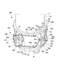
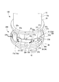
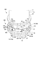
- FIG. 4 is a perspective view showing a resonance frequency adjusting mechanism in a first modification of the first embodiment of the superconducting accelerator.
- the upper and lower wires 22 may be a single continuous wire 22A, and the intermediate portion 22m may be fixed to the cable holding plate 27 or hooked via a pulley (not shown). By doing in this way, tension
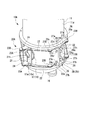
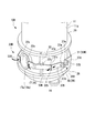
- FIG. 5 is a perspective view showing a resonance frequency adjusting mechanism in a second modification of the first embodiment of the superconducting accelerator.
- a plurality of (for example, two) bolts 29 or piezoelectric elements (not shown) are provided at intervals in the vertical direction as an interval adjusting member 28 for adjusting the interval between the cable holding plates 27. You may do it. Thereby, the interval between the cable holding plates 27 can be adjusted more stably. It is also possible to individually adjust the tension acting on the upper and lower wires 22 by making the interval between the cable holding plates 27 different between the upper and lower sides.
- FIG. 6 is a perspective view showing a resonance frequency adjusting mechanism provided in the superconducting accelerator of the second embodiment.
- FIG. 7 is a plan sectional view of the resonance frequency adjusting mechanism.
- the superconducting accelerator 10B in this embodiment includes an outer peripheral surface 11g of the refrigerant tank 11 above and below the end 17a of the beam introduction tube 17 and the end 18a of the beam lead-out tube 18, respectively. And a flange portion 26 protruding radially outward.
- the superconducting accelerator 10B includes a resonance frequency adjusting mechanism 20B.
- the resonance frequency adjusting mechanism 20B adjusts the distance between the end portion 17a of the beam introduction tube 17 and the end portion 18a of the beam outlet tube 18, and consequently the beam acceleration gap G (see FIG. 1), thereby adjusting the resonance frequency of the acceleration cavity 12. Make adjustments.
- the resonance frequency adjusting mechanism 20B includes a pressing member 31 and an arm displacement portion 35A.
- the pressing member 31 is provided at a position facing each other in the radial direction of the refrigerant tank 11 in the outer peripheral portion of the refrigerant tank 11.
- the pressing member 31 includes arms 32A provided on both sides in the circumferential direction of the refrigerant tank 11 with respect to the end portion 17a of the beam introduction tube 17 and the end portion 18a of the beam outlet tube 18 between the upper and lower flange portions 26, respectively. I have.
- Each arm 32 ⁇ / b> A extends along the outer peripheral surface 11 g continuously in the circumferential direction of the refrigerant tank 11, and an intermediate portion 32 c between the first end portion 32 a and the second end portion 32 b is provided between the upper and lower flange portions 26.
- the shaft (support shaft) 33 is provided so as to be swingable.
- the arm 32A has a first end portion 32a that abuts the end portion 17a of the beam introducing tube 17 and the end portion 18a of the beam guiding tube 18 in the axial direction of the beam introducing tube 17 and the beam guiding tube 18.
- the arm displacement portion 35A includes a push arm 37A, a push arm 37A on the beam introduction tube 17 side, and a distance adjusting member 38 for adjusting a distance between the push arm 37A on the beam outlet tube 18 side.
- the push arm 37A has a first end portion 37s connected to the second end portion 32b of the arm 32A via a pin 37p so as to be rotatable about an axis parallel to the central axis C (see FIG. 1) of the refrigerant tank 11. ing.
- a bracket portion 37d is formed on the second end portion 37t of the push arm 37A so as to protrude from the outer peripheral surface 11g of the refrigerant tank 11 toward the radially outer side of the refrigerant tank 11.
- the push arm 37 ⁇ / b> A on the beam introduction tube 17 side and the push arm 37 ⁇ / b> A on the beam lead-out tube 18 side are opposed to each other with a gap therebetween in the circumferential direction of the refrigerant tank 11.
- a bolt 39 can be used as the interval adjusting member 38.
- the bracket portion 37d of the push arm 37A on the beam introduction tube 17 side and the bracket portion 37d of the push arm 37A on the beam outlet tube 18 side approach and separate from each other.
- the operations of the arms 32A located on both sides in the circumferential direction are normally synchronized.
- the operations of the bolts 39 are synchronized in the distance adjusting members 38 provided on both sides in the radial direction of the refrigerant tank 11.
- the push arms 37A are disposed on the refrigerant tank 11 on the side closer to the beam introduction tube 17 and the side closer to the beam lead-out tube 18, respectively. It slides along the tangential direction of the outer peripheral surface 11g.
- the first end 37 s of the push arm 37 ⁇ / b> A displaces the second end 32 b of the arm 32 ⁇ / b> A, and each arm 32 ⁇ / b> A swings around the shaft 33.
- the bracket portions 37d of the push arm 37A are brought close to each other by the distance adjusting member 38, the second end portion 32b of each arm 32A is pulled to the first end portion 37s of the push arm 37A. Then, the arm 32A swings around the shaft 33, the first end portion 32a is displaced in a direction away from the outer peripheral surface 11g of the refrigerant tank 11, and the end portion 17a of the beam introducing tube 17 and the end of the beam outlet tube 18 are displaced.
- the force which presses the part 18a along the particle flow path direction of the charged particle beam B is weakened. In this way, the distance between the end 17a of the beam introduction tube 17 and the end 18a of the beam lead-out tube 18 and thus the beam acceleration gap G can be adjusted.
- the distance adjusting member 38 can be a piezoelectric element such as a piezoelectric element coaxially with the bolt 39. As a result, it is possible to perform rough adjustment of the arm 32A by rotating the bolt 39 and fine adjustment of the arm 32A by driving the piezoelectric element.
- a safety measure such as a protective cover may be installed around the resonance frequency adjusting mechanism 20B as in the first embodiment.
- the superconducting accelerator 10B of the second embodiment described above when the pair of push arms 37A are separated from each other by the arm displacement portion 35A, the respective arms 32A swing around the shaft 33. As a result, the end portion 17a of the beam introduction tube 17 and the end portion 18a of the beam outlet tube 18 which are the ends of the charged particle beam B in the particle flow direction in the acceleration cavity 12 are pressed by the first end portion 32a of the arm 32A. Is done. Then, since the acceleration cavity 12 is deformed and the length of the particle flow path of the charged particles is changed, the resonance frequency of the acceleration cavity 12 can be adjusted.
- the mechanism for adjusting the resonance frequency of the acceleration cavity 12 includes the arm 32A, the shaft 33, and the arm displacement portion 35A, a simple configuration is sufficient.
- the arm 32 ⁇ / b> A may be provided at a portion that presses the acceleration cavity 12 along the outer peripheral portion of the refrigerant tank 11, and a member that adjusts the resonance frequency greatly protrudes to the outer peripheral side of the acceleration cavity 12 or the refrigerant tank 11. Can be suppressed.
- the resonance frequency of the accelerating cavity 12 can be adjusted reliably, and the cost can be reduced, the size of the superconducting accelerator can be reduced, and the labor of layout work can be reduced.
- the arm 32A has a circumferential direction of the refrigerant tank 11 with respect to each of the end portion 17a of the beam introduction tube 17 and the end portion 18a of the beam lead-out tube 18 which are both ends in the particle flow direction of the charged particle beam B in the acceleration cavity 12. It is provided on both sides. With this configuration, the end 17a of the beam introducing tube 17 and the end 18a of the beam outlet tube 18 can be evenly pressed by the arms 32A provided on both sides in the circumferential direction.
- a flange portion 26 that supports the shaft 33 is provided on the outer peripheral portion of the refrigerant tank 11. Thereby, the strength of the flange portion 26 that supports the shaft 33 can be increased while reducing the thickness of the refrigerant tank 11.
- FIG. 8 is a perspective view showing a resonance frequency adjusting mechanism in a first modification of the second embodiment of the superconducting accelerator.
- each arm 32 ⁇ / b> B constituting the pressing member 31 of the resonance frequency adjusting mechanism 20 ⁇ / b> B in the first modification of the second embodiment is continuously along the outer circumferential surface 11 g in the circumferential direction of the refrigerant tank 11. It extends like so.
- the arms 32B are provided such that an intermediate portion 32c between the first end portion 32a and the second end portion 32b is swingable around a shaft 33 provided between the upper and lower flange portions 26.
- the second end portion 32b of the arm 32B is a concave surface having an arc shape in plan view.
- the arm displacement portion 35A includes a push arm 37B, a push arm 37B on the beam introduction tube 17 side, and a distance adjusting member 38 for adjusting a distance between the push arm 37B on the beam outlet tube 18 side.
- the push arm 37B has a convex surface in which the first end portion 37v has an arc shape in plan view, and is slidable on the concave surface of the second end portion 32b of the arm 32B.
- a bracket portion 37d is formed on the second end portion 37w of the push arm 37B so as to protrude from the outer peripheral surface 11g of the refrigerant tank 11 toward the radially outer side of the refrigerant tank 11.
- the second end portion 32b of each arm 32B is pressed and displaced by the first end portion 37v of the push arm 37B. . Then, the arm 32B swings around the shaft 33 while the second end portion 32b slides with respect to the first end portion 37v, so that the first end portion 32a approaches the outer peripheral surface 11g of the refrigerant tank 11. Displace. As a result, the first end portion 32a presses the end portion 17a of the beam introduction tube 17 and the end portion 18a of the beam outlet tube 18 along the particle flow path direction of the charged particle beam B. In this way, the distance between the end 17a of the beam introduction tube 17 and the end 18a of the beam lead-out tube 18 and thus the beam acceleration gap G can be adjusted.
- FIG. 9 is a perspective view showing a resonance frequency adjusting mechanism in a second modification of the second embodiment of the superconducting accelerator.
- the resonance frequency adjusting mechanism 20B in the second modification of the second embodiment includes a pressing member 31 and an arm displacement portion 35A.
- Each arm 32C constituting the pressing member 31 of the resonance frequency adjusting mechanism 20B extends along the outer peripheral surface 11g continuously in the circumferential direction of the refrigerant tank 11, and is intermediate between the first end portion 32a and the second end portion 32e.
- the portion 32c is provided so as to be swingable around a shaft 33 provided between the upper and lower flange portions 26.
- the first end portion 32a of the arm 32C abuts against the end portion 17a of the beam introduction tube 17 and the end portion 18a of the beam extraction tube 18 in the axial direction of the beam introduction tube 17 and the beam extraction tube 18.
- Each arm 32 ⁇ / b> C has a bracket portion 32 d that protrudes from the outer peripheral surface 11 g of the refrigerant tank 11 toward the radially outer side of the refrigerant tank 11 at the second end portion 32 e.
- the bracket 32d faces the arm 32C on the beam introduction tube 17 side and the arm 32C on the beam outlet tube 18 side with a space between each other in the circumferential direction of the refrigerant tank 11.
- the arm displacement portion 35A includes a distance adjusting member 38 that adjusts the distance between the bracket portion 32d of the arm 32C on the beam introduction tube 17 side and the bracket portion 32d of the arm 32C on the beam guide tube 18 side.
- a bolt 39 can be used as the interval adjusting member 38. By rotating the bolt 39 about the axis, the bracket portions 32d of the arms 32C facing each other approach and separate from each other.
- the arms 32C swing around the shaft 33. Specifically, when the bracket portions 32d of the arms 32C are separated from each other, the second end portion 32e is displaced in a direction away from the outer peripheral surface 11g of the refrigerant tank 11 in each arm 32C. Then, the arm 32 ⁇ / b> C swings around the shaft 33, and the first end portion 32 a is displaced in a direction approaching the outer peripheral surface 11 g of the refrigerant tank 11, whereby the first end portion 32 a becomes the end of the beam introduction tube 17.
- the portion 17 a and the end 18 a of the beam outlet tube 18 are pressed along the particle flow path direction of the charged particle beam B. Further, when the bracket portions 32d of the arms 32C are brought closer to each other by the distance adjusting member 38, the second end portion 32e is displaced in a direction approaching the outer peripheral surface 11g of the refrigerant tank 11 in each arm 32C. Then, the arm 32C swings around the shaft 33, and the first end portion 32a is displaced in a direction away from the outer peripheral surface 11g of the refrigerant tank 11, and the end portion 17a of the beam introduction tube 17 and the end of the beam outlet tube 18 are displaced. The force which presses the part 18a along the particle flow path direction of the charged particle beam B is weakened. In this way, the distance between the end 17a of the beam introduction tube 17 and the end 18a of the beam lead-out tube 18 and thus the beam acceleration gap G can be adjusted.
- the arms 32A are provided on both sides in the circumferential direction at each of the end 17a of the beam introduction tube 17 and the end 18a of the beam lead-out tube 18, but the present invention is not limited to this.
- FIG. 10 is a perspective view showing a resonance frequency adjusting mechanism in a third modification of the second embodiment of the superconducting accelerator.
- arms 32A are provided on both sides in the circumferential direction, and the first end portions 32a of these arms 32A are connected to each other. You may connect by the press plate 40A which has flexibility.
- an opening 40H serving as a flow path for the charged particle beam B is formed.
- the push arm 37A is displaced and the arm 32A is swung. Then, with the displacement of the first end portion 32a of the arm 32A, the pressing plate 40A bends. Specifically, the arm 32 ⁇ / b> A swings around the shaft 33 and the first end portion 32 a is displaced in a direction approaching the outer peripheral surface 11 g of the refrigerant tank 11.
- the pressing plate 40A bends with respect to both end portions 40a and 40a so that the central portion 40b protrudes in a direction approaching the outer peripheral surface 11g of the refrigerant tank 11, and the end portion 17a of the beam introducing tube 17 and the beam outlet tube 18 are formed. Is pushed along the particle flow path direction of the charged particle beam B.
- the arm 32A swings around the shaft 33 by the distance adjusting member 38 and the first end portion 32a is displaced in a direction away from the outer peripheral surface 11g of the refrigerant tank 11, the amount of bending of the pressing plate 40A is reduced and the pressing is performed.
- the central portion 40b of the plate 40A is displaced in a direction away from the outer peripheral surface 11g of the refrigerant tank 11. This weakens the force that presses the end 17a of the beam introduction tube 17 and the end 18a of the beam outlet tube 18 along the particle flow path direction of the charged particle beam B. In this way, the distance between the end 17a of the beam introduction tube 17 and the end 18a of the beam lead-out tube 18 and thus the beam acceleration gap G can be adjusted.
- the first end portions 32a of the arms 32A are connected by a pressing plate 40A, and the central portion 40b of the pressing plate 40A is protruded in a direction approaching the outer peripheral surface 11g of the refrigerant tank 11.
- the present invention is not limited to this.
- FIG. 11 is a perspective view showing a resonance frequency adjusting mechanism in a fourth modification of the second embodiment of the superconducting accelerator.
- arms 32A are provided on both sides in the circumferential direction, and between the first end portions 32a of these arms 32A.
- a flexible pressing plate 40B may be provided.
- the first end portion 32 a of the arm 32 ⁇ / b> A becomes the outer peripheral surface 11 g of the refrigerant tank 11. Displacement in a direction approaching.
- the pressing plate 40B is bent so that both end portions 40s protrude in a direction approaching the outer peripheral surface 11g of the refrigerant tank 11 with respect to the central portion 40b, and the end portion 17a of the beam introduction tube 17 and the beam outlet tube 18 are formed. Is pushed along the particle flow path direction of the charged particle beam B.
- the end portion 17a of the beam introduction tube 17 and the end portion 18a of the beam outlet tube 18 are pressed by bending the pressing plate 40A and the pressing plate 40B.
- FIG. 12 is a perspective view showing a resonance frequency adjusting mechanism in a fifth modification of the second embodiment of the superconducting accelerator.
- arms 32A are provided on both sides in the circumferential direction, and between the first ends 32a of these arms 32A.
- a connecting plate 40C may be provided. Both end portions 40s of the connection plate 40C are rotatably connected to the first end portion 32a of the arm 32A via hinge pins 40p.
- the present invention is not limited to the above-described embodiment, and includes various modifications made to the above-described embodiment without departing from the spirit of the present invention. That is, the specific shapes, configurations, and the like given in the embodiment are merely examples, and can be changed as appropriate.
- the flange portions 26 are provided above and below the resonance frequency adjusting mechanisms 20A and 20B, and each flange portion 26 is continuous over the entire circumference in the circumferential direction of the refrigerant tank 11.
- FIG. 13 is a perspective view showing a modification of the flange portion provided in the refrigerant tank.
- FIG. 14 is a perspective view illustrating an example of a support convex portion provided in the refrigerant tank.
- the flange portion (supporting convex portion) 26 ′ may be provided only in a part in the circumferential direction.
- the support convex portions 26 ′′ may be provided intermittently at intervals in the circumferential direction of the refrigerant tank 11, and may be provided in a block shape only at a portion that supports the pulley 23 ⁇ / b> B and the shaft 33. Good.
- the refrigerant tank 11 shown in FIGS. 13 and 14 can also be provided with the resonance frequency adjusting mechanisms 20A and 20B shown in the first and second embodiments.
- the resonance frequency adjusting mechanisms 20A and 20B are provided in the coaxial quarter-wavelength type superconducting accelerators 10A and 10B.
- the present invention is not limited to this.
- the resonance frequency adjusting mechanism 20A similarly to the half-wavelength superconducting accelerator 10C, the resonance frequency adjusting mechanism 20A, so that both ends of the acceleration cavity 12C in the particle flow direction of the charged particle beam B are sandwiched. 20B can be provided.
- a resonance frequency adjusting mechanism is arranged so as to sandwich both ends of the acceleration cavity 12D in the particle flow direction of the charged particle beam B.
- 20A and 20B can be provided.
- the resonance frequency adjusting mechanism 20A is sandwiched between both ends of the acceleration cavity 12D in the particle flow direction of the charged particle beam B.
- resonance frequency adjustment mechanisms 20A, 20B may be provided so that the acceleration cavity 12D is pressed at both ends in the radial direction orthogonal to the particle flow path direction of the charged particle beam B.
- resonance frequency adjustment mechanisms 20A and 20B that press from both ends in the radial direction orthogonal to the particle flow path direction of the charged particle beam B and resonance frequency adjustment mechanisms that press from both ends of the charged particle beam B in the particle flow path direction. 20A and 20B may be used in combination.
- each cell 12c of the acceleration cavity 12E is charged with charged particles.
- Resonance frequency adjusting mechanisms 20A and 20B that press so as to be sandwiched between both ends in the radial direction orthogonal to the particle flow path direction of the beam B may be provided.
Landscapes
- Physics & Mathematics (AREA)
- Engineering & Computer Science (AREA)
- Plasma & Fusion (AREA)
- Spectroscopy & Molecular Physics (AREA)
- Particle Accelerators (AREA)
Abstract
超伝導加速器は、超伝導状態で荷電粒子ビームを加速する空間を形成する加速空洞と、加速空洞の外周側に配置され、加速空洞との隙間に加速空洞を冷却する冷媒が充填される冷媒槽(11)と、を備える。超伝導加速器は、冷媒槽(11)の外周部に設けられ、加速空洞における荷電粒子ビームのビーム軸方向の両端部、またはビーム軸方向に直交する方向の両端部にそれぞれ設けられた一対の押圧部材(21)を更に備える。超伝導加速器は、冷媒槽(11)の外周部に連続して設けられ、一対の押圧部材(21)同士を接近させる方向の張力を発生するワイヤー(22)と、ワイヤー(22)で発生する張力を調整する張力調整部(25)を更に備える。
Description
この発明は、超伝導加速器に関する。
本願は、2015年6月30日に、日本に出願された特願2015-131089号に基づき優先権を主張し、その内容をここに援用する。
本願は、2015年6月30日に、日本に出願された特願2015-131089号に基づき優先権を主張し、その内容をここに援用する。
電子や陽子などの荷電粒子を、超伝導加速空洞を用いて加速する超伝導加速器が知られている。超伝導加速器は、超伝導材料で形成された超伝導加速空洞を、液体ヘリウム等の冷媒で冷却することによって超伝導化する。これによって、超伝導加速空洞の電気抵抗がほぼゼロとなり、電力損失なく、荷電粒子の加速を効率良く行うことができる。
このような超伝導加速器においては、超伝導加速空洞において荷電粒子を加速する高周波電場を形成するギャップの長さを調整することで、超伝導加速空洞の共振周波数調整を行う。
特許文献1には、超伝導加速空洞を収容する冷媒槽の軸方向の長さを、冷媒槽に設けられた二つのフランジ間の距離を伸縮させることで調整する構成が開示されている。この構成においては、二つのフランジのそれぞれに密着させた座板同士の間に、テーパ面を有したクサビ状のナットを設け、ボルトによってナットを座板の表面に沿って移動させることで、座板同士の間隔を調整する。
超伝導加速空洞の冷媒槽の径方向両側に、冷媒槽の直径よりも長いビーム部材をそれぞれ設け、これらビーム部材の両端部同士を、冷媒槽の径方向両側でネジ部材等によって連結した構成の共振周波数調整手法も提案されている。この構成によれば、ネジ部材によってビーム部材同士の間隔を増減させることによって、超伝導加速空洞を変形させて粒子通路の長さを変え、超伝導加速空洞の共振周波調整を行うことができる。
上述した共振周波数調整手法は、二つの座板の間に設けたクサビ状のナットを、座板の表面に沿って移動させることによって冷媒槽全体の軸方向長さを変動させる。そのため、座板やナットには大きな力が作用する。したがって、座板やナットを強固なものとしなければならない。すると、座板やナットが大型化し、超伝導加速器の高コスト化、大型化に繋がる。座板やナットの周囲に他の機器等を設ける場合、座板やナットと、他の機器とが干渉しないようにレイアウトしなければならず、その作業に手間がかかる。
冷媒槽の両端に設けたビーム同士の間隔をネジ部材によって増減させる構成においては、ネジ部材によってビーム同士の間隔を増減させると、ビームに曲げモーメントが作用する。この曲げモーメントに抗するためには、ビームを強固なものとしなければならず、その結果、特許文献1に開示された構成と同様、超伝導加速器の高コスト化、大型化、他の機器との干渉を避けるためのレイアウト作業の手間増大等に繋がる。
この発明は、超伝導加速空洞の共振周波数調整を確実に行うことができ、しかも、低コスト化、超伝導加速器の小型化、レイアウト作業の手間軽減を図ることができる超伝導加速器を提供することを目的とする。
この発明は、超伝導加速空洞の共振周波数調整を確実に行うことができ、しかも、低コスト化、超伝導加速器の小型化、レイアウト作業の手間軽減を図ることができる超伝導加速器を提供することを目的とする。
この発明の第一態様によれば、超伝導加速器は、超伝導状態で荷電粒子ビームを加速する空間を形成する加速空洞と、前記加速空洞の外周側に配置され、前記加速空洞との隙間に前記加速空洞を冷却する冷媒が充填される冷媒槽と、を備える。この超伝導加速器は、前記冷媒槽の外周部に設けられ、前記加速空洞における前記荷電粒子ビームのビーム軸方向の両端部、または前記ビーム軸方向に直交する方向の両端部にそれぞれ設けられた一対の押圧部材を更に備える。この超伝導加速器は、前記冷媒槽の外周部に連続して設けられ、一対の前記押圧部材同士を接近させる方向の張力を発生する張力部材と、前記張力部材で発生する前記張力を調整する張力調整部と、を更に備える。
このように構成することで、張力調整部により張力部材で張力を発生すると、一対の押圧部材同士が互いに接近する。これによって、加速空洞における荷電粒子ビームのビーム軸方向の両端部、または加速空洞におけるビーム軸方向に直交する方向の両端部が押圧される。すると、加速空洞が変形して荷電粒子の粒子流路の長さが変わるので、加速空洞の共振周波数を調整することができる。
さらに、加速空洞の共振周波数を調整するための機構は、押圧部材と、張力部材と、張力調整部とからなるので、簡易な構成で済む。
さらに、張力部材を、冷媒槽の外周部に連続して設けるので、押圧部材は、加速空洞から側方に突出する寸法を最小限に抑え、少なくとも加速空洞を押圧する部位に設ければよい。したがって、共振周波数を調整する部材が、加速空洞や冷媒槽の外周側に大きく張り出すのを抑えることができる。
さらに、加速空洞の共振周波数を調整するための機構は、押圧部材と、張力部材と、張力調整部とからなるので、簡易な構成で済む。
さらに、張力部材を、冷媒槽の外周部に連続して設けるので、押圧部材は、加速空洞から側方に突出する寸法を最小限に抑え、少なくとも加速空洞を押圧する部位に設ければよい。したがって、共振周波数を調整する部材が、加速空洞や冷媒槽の外周側に大きく張り出すのを抑えることができる。
この発明の第二態様によれば、超伝導加速器は、第一態様の前記張力部材がワイヤーであり、前記冷媒槽の外周部に周方向に間隔を空けて、前記ワイヤーが掛止される複数の滑車を備えるようにしてもよい。
このように構成することで、張力調整部によりワイヤーを引っ張れば、一対の押圧部材で加速空洞における荷電粒子ビームの粒子流路の長さを調整することができる。ワイヤーは、冷媒槽の外周部に設けた複数の滑車に係止することで、冷媒槽と干渉することなく、冷媒槽の外周部に沿うように設けることができる。
このように構成することで、張力調整部によりワイヤーを引っ張れば、一対の押圧部材で加速空洞における荷電粒子ビームの粒子流路の長さを調整することができる。ワイヤーは、冷媒槽の外周部に設けた複数の滑車に係止することで、冷媒槽と干渉することなく、冷媒槽の外周部に沿うように設けることができる。
この発明の第三態様によれば、超伝導加速器は、第二態様の前記冷媒槽の外周部に、前記冷媒槽の外周部から外周側に突出し、前記滑車を回転自在に支持する支持凸部が設けられているようにしてもよい。
このように構成することで、滑車を冷媒槽の外周側に設けることができる。これによって、ワイヤーを、冷媒槽に干渉しないように、冷媒槽の外周部に連続して配置することができる。
さらに、滑車を、冷媒槽の外周部に設けられた支持凸部で支持することで、冷媒槽だけで滑車を支持する強度を確保する必要がなくなる。これによって、冷媒槽の薄肉化を図り、冷媒槽の軽量化、熱容量の縮小化を図ることができる。
このように構成することで、滑車を冷媒槽の外周側に設けることができる。これによって、ワイヤーを、冷媒槽に干渉しないように、冷媒槽の外周部に連続して配置することができる。
さらに、滑車を、冷媒槽の外周部に設けられた支持凸部で支持することで、冷媒槽だけで滑車を支持する強度を確保する必要がなくなる。これによって、冷媒槽の薄肉化を図り、冷媒槽の軽量化、熱容量の縮小化を図ることができる。
この発明の第四態様によれば、超伝導加速器は、第三態様において、前記支持凸部が、前記冷媒槽の前記外周部に沿って、周方向に連続して形成されているようにしてもよい。
このように構成することで、滑車を支持する支持凸部の強度を高めることができる。これによって、冷媒槽の薄肉化による軽量化、熱容量の縮小化を、より一層効果的に図ることができる。
このように構成することで、滑車を支持する支持凸部の強度を高めることができる。これによって、冷媒槽の薄肉化による軽量化、熱容量の縮小化を、より一層効果的に図ることができる。
この発明の第五態様によれば、超伝導加速器は、第二から第四態様の何れか一つの態様において、前記押圧部材に、前記滑車が設けられているようにしてもよい。
このように構成することで、張力部材の張力が、滑車を介し、加速空洞の押圧部位に配置された押圧部材に直接作用する。これによって、押圧部材で加速空洞を効率よく押圧することができる。さらに、押圧部材を、加速空洞の押圧部位のみに突き当たるように設ければよく、押圧部材の小型化を図ることができる。
このように構成することで、張力部材の張力が、滑車を介し、加速空洞の押圧部位に配置された押圧部材に直接作用する。これによって、押圧部材で加速空洞を効率よく押圧することができる。さらに、押圧部材を、加速空洞の押圧部位のみに突き当たるように設ければよく、押圧部材の小型化を図ることができる。
この発明の第六態様によれば、超伝導加速器は、超伝導状態で荷電粒子ビームを加速する空間を形成する加速空洞と、前記加速空洞の外周側に配置され、前記加速空洞との隙間に前記加速空洞を冷却する冷媒が充填される冷媒槽と、を備える。超伝導加速器は、前記冷媒槽の外周部に設けられ、前記加速空洞における前記荷電粒子ビームのビーム軸方向の両方の端部、または前記ビーム軸方向に直交する方向の両端部にそれぞれ配され、前記冷媒槽の外周部に設けられた支持軸回りに揺動自在に支持されるとともに、第一端部が前記端部に対向して設けられた一対のアームを更に備える。超伝導加速器は、一対の前記アームの第二端部同士を離間させる方向に変位させることによって、前記アームの前記第一端部で前記端部を押圧させるアーム変位部を更に備える。
このように構成することで、アーム変位部により、一対のアームの第二端部同士を離間させると、それぞれのアームが、支持軸回りに揺動し、アームの第一端部が、加速空洞における荷電粒子ビームのビーム軸方向の端部、またはビーム軸方向に直交する方向の端部を押圧する。これによって、加速空洞における荷電粒子ビームのビーム軸方向の両端部、またはビーム軸方向に直交する方向の両端部が押圧され、加速空洞が変形して荷電粒子の粒子流路の長さが変わるので、加速空洞の共振周波数を調整することができる。
加速空洞の共振周波数を調整するための機構は、アームと、支持軸と、アーム変位部とからなるので、簡易な構成で済む。
さらに、アームは、冷媒槽の外周部に沿って加速空洞を押圧する部位に設ければよく、共振周波数を調整する部材が、加速空洞や冷媒槽の外周側に大きく張り出すのを抑えることができる。
このように構成することで、アーム変位部により、一対のアームの第二端部同士を離間させると、それぞれのアームが、支持軸回りに揺動し、アームの第一端部が、加速空洞における荷電粒子ビームのビーム軸方向の端部、またはビーム軸方向に直交する方向の端部を押圧する。これによって、加速空洞における荷電粒子ビームのビーム軸方向の両端部、またはビーム軸方向に直交する方向の両端部が押圧され、加速空洞が変形して荷電粒子の粒子流路の長さが変わるので、加速空洞の共振周波数を調整することができる。
加速空洞の共振周波数を調整するための機構は、アームと、支持軸と、アーム変位部とからなるので、簡易な構成で済む。
さらに、アームは、冷媒槽の外周部に沿って加速空洞を押圧する部位に設ければよく、共振周波数を調整する部材が、加速空洞や冷媒槽の外周側に大きく張り出すのを抑えることができる。
この発明の第七態様によれば、超伝導加速器は、第六態様において、前記アームが、前記加速空洞における前記荷電粒子ビームのビーム軸方向の両端部、または前記ビーム軸方向に直交する方向の両端部のそれぞれに対し、前記冷媒槽の周方向の両側に延びるようにしてもよい。
このように構成することで、加速空洞のビーム軸方向の端部、または加速空洞のビーム軸方向に直交する方向の端部のそれぞれを、周方向両側に設けられたアームによって均等に押圧することができる。
このように構成することで、加速空洞のビーム軸方向の端部、または加速空洞のビーム軸方向に直交する方向の端部のそれぞれを、周方向両側に設けられたアームによって均等に押圧することができる。
この発明の第八態様によれば、超伝導加速器は、第六又は第七態様において、前記冷媒槽の外周部に、前記冷媒槽の外周部から外周側に突出し、前記支持軸を支持する支持凸部が設けられているようにしてもよい。
このように構成することで、冷媒槽の薄肉化を図りつつ、支持軸を支持する支持凸部の強度を確保することができる。
このように構成することで、冷媒槽の薄肉化を図りつつ、支持軸を支持する支持凸部の強度を確保することができる。
この発明の第九態様によれば、超伝導加速器は、第八態様において、前記支持凸部が、前記冷媒槽の前記外周部に沿って周方向に連続して形成されているようにしてもよい。
このように構成することで、滑車を支持する支持凸部の強度を高めることができる。
このように構成することで、滑車を支持する支持凸部の強度を高めることができる。
上述した超伝導加速器によれば、超伝導加速空洞の共振周波数調整を確実に行うことができ、しかも、低コスト化、超伝導加速器の小型化、レイアウト作業の手間軽減を図ることができる。
以下、この発明の実施形態に係る超伝導加速器を図面に基づき説明する。
(第一実施形態)
図1は、この実施形態の超伝導加速器の構成を示す立断面図である。図2は、上記超伝導加速器に備えた共振周波数調整機構を示す斜視図である。図3は、上記共振周波数調整機構の平断面図である。
図1に示すように、この実施形態の超伝導加速器10Aは、例えば、同軸1/4波長型超伝導加速器(QWR:Quarter Wave Resonator)であり、冷媒が充填される冷媒槽11内に、電子や陽子などの荷電粒子からなる荷電粒子ビームBを加速する加速空洞12を備える。
(第一実施形態)
図1は、この実施形態の超伝導加速器の構成を示す立断面図である。図2は、上記超伝導加速器に備えた共振周波数調整機構を示す斜視図である。図3は、上記共振周波数調整機構の平断面図である。
図1に示すように、この実施形態の超伝導加速器10Aは、例えば、同軸1/4波長型超伝導加速器(QWR:Quarter Wave Resonator)であり、冷媒が充填される冷媒槽11内に、電子や陽子などの荷電粒子からなる荷電粒子ビームBを加速する加速空洞12を備える。
冷媒槽11は、上下方向に延びる中心軸Cを有した円柱状の真空容器であり、その上端面11aおよび下端面11bは閉塞されている。この冷媒槽11は、外部からの地磁気や輻射熱の影響を低減するシールド層を備えていてもよい。
加速空洞12は、ニオブ等の超伝導材料から形成され、上下方向に連続する中空チャンバ状をなしている。この加速空洞12は、冷媒槽11の内周面11fとの間に隙間Sが形成される。
加速空洞12は、外周面12fの下部に、円形断面のビーム導入管17およびビーム導出管18を備えている。ビーム導入管17、ビーム導出管18は、冷媒槽11の中心軸Cに直交する径方向で互いに対向する位置に設けられている。ビーム導入管17およびビーム導出管18は、それぞれ加速空洞12の外周面12fから径方向外方に向かって延び、冷媒槽11を貫通して冷媒槽11の径方向外方に突出している。
加速空洞12は、外周面12fの下部に、円形断面のビーム導入管17およびビーム導出管18を備えている。ビーム導入管17、ビーム導出管18は、冷媒槽11の中心軸Cに直交する径方向で互いに対向する位置に設けられている。ビーム導入管17およびビーム導出管18は、それぞれ加速空洞12の外周面12fから径方向外方に向かって延び、冷媒槽11を貫通して冷媒槽11の径方向外方に突出している。
加速空洞12は、冷媒槽11の中心軸Cに沿って上下方向に延びるよう形成されたステム13を備える。ステム13は、加速空洞12の上端部から下方に向かって凹み、上方から下方に向かってその内径が漸次縮小している。ステム13の下端部には、ステム13に連続して環状に形成された環状流路13cが一体に形成されている。この環状流路13cの内方には、加速空洞12のビーム導入管17およびビーム導出管18と同軸上に、ビーム流通管部19が形成されている。
加速空洞12は、その上端部に、冷媒槽11の上端面11aを貫通し、中空の加速空洞12内に連通する接続口15を備えている。この接続口15を通し、真空ポンプ等により真空引きすることで、加速空洞12内を真空状態にすることができる。
加速空洞12は、その下端部に、入力結合部16を備えている。この入力結合部16から、高周波の電力を入力することで、加速空洞12内の空間Aには、荷電粒子ビームBを加速する電界が発生する。
図1に示すように、冷媒槽11は、上端面11aに形成され、冷媒槽11内に冷媒を供給する冷媒供給口14を備えている。この冷媒供給口14から送り込まれる冷媒は、冷媒槽11の内周面11fと加速空洞12の外周面12fとの間の隙間Sと、ステム13および環状流路13c内とに送り込まれる。ここで、冷媒としては、液体ヘリウム等を用いることができる。
このような超伝導加速器10Aにおいては、冷媒槽11内に送り込んだ冷媒によって加速空洞12が冷却され、超伝導状態とされる。荷電粒子ビームBは、加速空洞12の径方向における第一の側に設けられたビーム導入管17から加速空洞12内に入り、ステム13の下端部に設けられた環状流路13cの内方に形成されたビーム流通管部19を経て、加速空洞12の径方向における第二の側に設けられたビーム導出管18から加速空洞12外に送り出される。
このような超伝導加速器10Aは、荷電粒子ビームBの粒子流路に沿って複数個が連接される。互いに隣接する超伝導加速器10A同士は、一方の超伝導加速器10Aの加速空洞12に形成されたビーム導入管17と、他方の超伝導加速器10Aの加速空洞12に形成されたビーム導出管18とを、接続管(図示無し)等を介して連結される。
図1、図2に示すように、冷媒槽11の外周面11gには、フランジ部26が形成されている。フランジ部26は、ビーム導入管17の端部17aおよびビーム導出管18の端部18aの上方と、下方とにそれぞれ形成されている。これらフランジ部26は、それぞれ冷媒槽11の外周面11gから径方向外方に突出するように形成されている。この実施形態において、フランジ部26は、冷媒槽11の外周面11gに沿って周方向に連続する環状に形成されている。
各超伝導加速器10Aは、共振周波数調整機構20Aを備えている。共振周波数調整機構20Aは、ビーム導入管17の端部17aとビーム導出管18の端部18aとの間隔、ひいてはビーム加速ギャップGを調整することで、加速空洞12の共振周波数調整を行う。
図2、図3に示すように、共振周波数調整機構20Aは、押圧部材21と、ワイヤー(張力部材)22と、滑車23A、23Bと、張力調整部25と、を備えている。
図2、図3に示すように、共振周波数調整機構20Aは、押圧部材21と、ワイヤー(張力部材)22と、滑車23A、23Bと、張力調整部25と、を備えている。
押圧部材21は、冷媒槽11の外周部において冷媒槽11の径方向で互いに対向する位置に設けられている。言い換えれば、押圧部材21は、冷媒槽11を挟んで対称な位置に二枚一対で設けられている。この実施形態では、押圧部材21は、上下2つのフランジ部(支持凸部)26の間に位置し、ビーム導入管17の端部17a、ビーム導出管18の端部18aにそれぞれ当接する。
押圧部材21は、矩形板状で、ビーム導入管17、ビーム導出管18に連通する開口部21hが中央部に形成されて、開口部21hを中心として冷媒槽11の周方向に二分割されている。
押圧部材21は、冷媒槽11の中心軸C方向の高さ寸法が、ビーム導入管17、ビーム導出管18の外径よりも大きい。これによって、押圧部材21の上端部21aおよび下端部21bは、ビーム導入管17、ビーム導出管18の上下に張り出している。さらに、押圧部材21は、荷電粒子ビームBのビーム進行方向と冷媒槽11の中心軸Cとに直交する方向の幅寸法が、高さ寸法よりも小さい。
押圧部材21は、矩形板状で、ビーム導入管17、ビーム導出管18に連通する開口部21hが中央部に形成されて、開口部21hを中心として冷媒槽11の周方向に二分割されている。
押圧部材21は、冷媒槽11の中心軸C方向の高さ寸法が、ビーム導入管17、ビーム導出管18の外径よりも大きい。これによって、押圧部材21の上端部21aおよび下端部21bは、ビーム導入管17、ビーム導出管18の上下に張り出している。さらに、押圧部材21は、荷電粒子ビームBのビーム進行方向と冷媒槽11の中心軸Cとに直交する方向の幅寸法が、高さ寸法よりも小さい。
ワイヤー22は、冷媒槽11の外周部において、周方向に連続するよう設けられている。ワイヤー22は、上下のフランジ部26の間で、冷媒槽11の中心軸C方向の上下に間隔を空けて二本一対で設けられている。一方のワイヤー22は、ビーム導入管17の端部17aおよびビーム導出管18の端部18aの上方に配され、他方のワイヤー22は、ビーム導入管17の端部17aおよびビーム導出管18の端部18aの下方に配されている。これら二本のワイヤー22は、冷媒槽11の外周部において、複数の滑車23A、23Bに掛け回され、冷媒槽11の周方向のほぼ半周にわたって連続するよう設けられている。
滑車23A、23Bは、冷媒槽11の外周部に、周方向に間隔を空けて複数個が設けられている。これら複数の滑車23A、23Bは、ビーム導入管17の端部17aおよびビーム導出管18の端部18aの上方と、下方とに、それぞれ配されている。
滑車23Aは、各押圧部材21の上端部、下端部にそれぞれ設けられたブラケット24に、冷媒槽11の中心軸Cと平行な軸回りに回動自在に支持されている。ブラケット24は、押圧部材21から冷媒槽11の径方向外方に向かって突出するよう形成されている。
滑車23Bは、冷媒槽11の周方向において、冷媒槽11の径方向における第一の側に配された滑車23Aと、第二の側に配された滑車23Aとの間に配置されている。この実施形態では、滑車23Bは、冷媒槽11の径方向における第一の側に配された滑車23Aと、第二の側に配された滑車23Aとの間に、冷媒槽11の周方向に間隔を空けて2個が設けられている。
各滑車23Bは、上方のフランジ部26の下部、または下方のフランジ部26の上部に設けられている。各滑車23Bは、フランジ部26に設けられた冷媒槽11の中心軸Cに平行な回転軸23c回りに、回動自在に設けられている。
滑車23Aは、各押圧部材21の上端部、下端部にそれぞれ設けられたブラケット24に、冷媒槽11の中心軸Cと平行な軸回りに回動自在に支持されている。ブラケット24は、押圧部材21から冷媒槽11の径方向外方に向かって突出するよう形成されている。
滑車23Bは、冷媒槽11の周方向において、冷媒槽11の径方向における第一の側に配された滑車23Aと、第二の側に配された滑車23Aとの間に配置されている。この実施形態では、滑車23Bは、冷媒槽11の径方向における第一の側に配された滑車23Aと、第二の側に配された滑車23Aとの間に、冷媒槽11の周方向に間隔を空けて2個が設けられている。
各滑車23Bは、上方のフランジ部26の下部、または下方のフランジ部26の上部に設けられている。各滑車23Bは、フランジ部26に設けられた冷媒槽11の中心軸Cに平行な回転軸23c回りに、回動自在に設けられている。
張力調整部25は、冷媒槽11の周方向において互いに間隔を空けて対向配置された一対のケーブル保持プレート27と、これらケーブル保持プレート27の間隔を調整する間隔調整部材28と、を備えている。
各ケーブル保持プレート27には、その上端部27aおよび下端部27bに、上下のワイヤー22の端部22aが固定されている。
間隔調整部材28は、例えばボルト29を用いることができる。ボルト29は、その頭部29aに近い側が一方のケーブル保持プレート27に形成されたネジ挿通孔27hに挿通され、雄ネジ部が形成された軸部29bが孔27nにねじ込まれている。ボルト29を、図示しないモータの駆動軸に設けられたウォームギヤ29gによって軸回りに回転させることで、互いに対向するケーブル保持プレート27同士が接近および離間する。これらケーブル保持プレート27の接近および離間によって、上下のワイヤー22に作用する張力が調整される。
図3に示すように、間隔調整部材28に、ピエゾ素子等の圧電素子29Pを用いることができる。この実施形態では、張力調整部25は、冷媒槽11の径方向両側にそれぞれ設けられ、一方の張力調整部25の間隔調整部材28にボルト29を用い、他方の張力調整部25の間隔調整部材28に圧電素子29Pを用いる。これにより、一方の張力調整部25の間隔調整部材28でボルト29を回転させることで、ワイヤー22の張力の粗調整を行い、他方の張力調整部25の間隔調整部材28で圧電素子を駆動することでワイヤー22の張力の微調整を行うことができる。
このような構成において、張力調整部25でケーブル保持プレート27の間隔を調整することによって、ワイヤー22に作用する張力を大きくすれば、ワイヤー22の張力が滑車23Aを介して押圧部材21に伝達される。具体的には、2つのケーブル保持プレート27の間隔を狭めれば、ワイヤー22の張力により、冷媒槽11の径方向において互いに対向する押圧部材21同士が接近し、ビーム導入管17の端部17a、ビーム導出管18の端部18aを、荷電粒子ビームBの粒子流路方向に沿って押圧することができる。ワイヤー22が張力を発揮している状態で、ケーブル保持プレート27の間隔を広げれば、ワイヤー22の張力が低くなって互いに対向する押圧部材21同士が離間し、ビーム導入管17の端部17a、ビーム導出管18の端部18aを、荷電粒子ビームBの粒子流路方向に沿って押圧する力が弱まる。このようにして、ビーム導入管17の端部17aとビーム導出管18の端部18aとの間隔、ひいてはビーム加速ギャップGを調整することができる。
上記したような構成に加え、共振周波数調整機構20Aの周囲に、防護カバー等の安全対策工を設置してもよい。
したがって、上述した第一実施形態の超伝導加速器10Aによれば、ワイヤー22で張力を発生すると、一対の押圧部材21同士が互いに接近する。これによって、加速空洞12における荷電粒子ビームBの粒子流路方向の両端部が押圧され、加速空洞12が変形して荷電粒子ビームBの粒子流路の長さが変わるので、加速空洞12の共振周波数を調整することができる。
さらに、加速空洞12の共振周波数を調整するための機構は、押圧部材21と、ワイヤー22と、張力調整部25とからなるので、簡易な構成で済む。
さらに、ワイヤー22を、冷媒槽11の外周部に連続して設けるので、押圧部材21は、加速空洞12から側方に突出する寸法を抑え、少なくとも加速空洞12を押圧する部位であるビーム導入管17の端部17aとビーム導出管18の端部18aとに設ければよい。したがって、共振周波数を調整する部材が、加速空洞12や冷媒槽11の外周側に大きく張り出すのを抑えることができる。
このような超伝導加速器10によれば、加速空洞12の共振周波数調整を確実に行うことができ、しかも、低コスト化、超伝導加速器の小型化、レイアウト作業の手間軽減を図ることができる。
さらに、加速空洞12の共振周波数を調整するための機構は、押圧部材21と、ワイヤー22と、張力調整部25とからなるので、簡易な構成で済む。
さらに、ワイヤー22を、冷媒槽11の外周部に連続して設けるので、押圧部材21は、加速空洞12から側方に突出する寸法を抑え、少なくとも加速空洞12を押圧する部位であるビーム導入管17の端部17aとビーム導出管18の端部18aとに設ければよい。したがって、共振周波数を調整する部材が、加速空洞12や冷媒槽11の外周側に大きく張り出すのを抑えることができる。
このような超伝導加速器10によれば、加速空洞12の共振周波数調整を確実に行うことができ、しかも、低コスト化、超伝導加速器の小型化、レイアウト作業の手間軽減を図ることができる。
さらに、張力調整部25によりワイヤー22を引っ張れば、一対の押圧部材21で加速空洞12における荷電粒子ビームBの粒子流路の長さを調整することができ、共振周波数調整を容易かつ確実に行うことができる。
冷媒槽11の外周部に、滑車23Bを回転自在に支持するフランジ部26が設けられている。このように構成することで、ワイヤー22を、冷媒槽11に干渉しないように、冷媒槽11の外周部に連続して配置することができる。
さらに、滑車23A,23Bを、冷媒槽11の外周部に設けられたフランジ部26で支持することで、冷媒槽11だけで滑車23A,23Bを支持する強度を確保する必要がなくなる。これによって、冷媒槽11の薄肉化を図り、冷媒槽11の軽量化、熱容量の縮小化を図ることができる。
さらに、滑車23A,23Bを、冷媒槽11の外周部に設けられたフランジ部26で支持することで、冷媒槽11だけで滑車23A,23Bを支持する強度を確保する必要がなくなる。これによって、冷媒槽11の薄肉化を図り、冷媒槽11の軽量化、熱容量の縮小化を図ることができる。
さらに、フランジ部26は、冷媒槽11の外周部に沿って、周方向に連続して形成されている。このようにフランジ部26を環状に形成することで、滑車23A,23Bを支持するフランジ部26の強度を高めることができ、冷媒槽11を効果的に補強することができる。
さらに、押圧部材21に、滑車23A,23Bが設けられている。このように構成することで、ワイヤー22の張力が、滑車23A,23Bを介し、加速空洞12の押圧部位に配置された押圧部材21に直接作用する。これによって、押圧部材21によって、加速空洞12を効率よく押圧することができる。
(第一実施形態の変形例)
第一実施形態では、上下のワイヤー22を、ケーブル保持プレート27の上端部27aと下端部27bにそれぞれ固定するようにしたが、これに限るものではない。
(第一変形例)
図4は、上記超伝導加速器の第一実施形態の第一変形例における共振周波数調整機構を示す斜視図である。
この図4に示すように、上下のワイヤー22を連続した一本のワイヤー22Aとし、その中間部22mをケーブル保持プレート27に固定、または滑車(図示無し)を介して掛止してもよい。このようにすることで、上下のワイヤー22に、均等に張力を作用させることができる。
第一実施形態では、上下のワイヤー22を、ケーブル保持プレート27の上端部27aと下端部27bにそれぞれ固定するようにしたが、これに限るものではない。
(第一変形例)
図4は、上記超伝導加速器の第一実施形態の第一変形例における共振周波数調整機構を示す斜視図である。
この図4に示すように、上下のワイヤー22を連続した一本のワイヤー22Aとし、その中間部22mをケーブル保持プレート27に固定、または滑車(図示無し)を介して掛止してもよい。このようにすることで、上下のワイヤー22に、均等に張力を作用させることができる。
(第二変形例)
さらに、上記第一実施形態では、ケーブル保持プレート27同士の間隔を調整する間隔調整部材28として、1つのボルト29または圧電素子(図示無し)を用いるようにしたが、これに限るものではない。
図5は、上記超伝導加速器の第一実施形態の第二変形例における共振周波数調整機構を示す斜視図である。
この図5に示すように、ケーブル保持プレート27同士の間隔を調整する間隔調整部材28として、複数本(例えば2つ)のボルト29または圧電素子(図示無し)を、上下に間隔を空けて設けるようにしてもよい。これによって、ケーブル保持プレート27同士の間隔を、より安定して調整することができる。ケーブル保持プレート27同士の間隔を、上下で異ならせ、上下のワイヤー22に作用させる張力を個別に調整することもできる。
さらに、上記第一実施形態では、ケーブル保持プレート27同士の間隔を調整する間隔調整部材28として、1つのボルト29または圧電素子(図示無し)を用いるようにしたが、これに限るものではない。
図5は、上記超伝導加速器の第一実施形態の第二変形例における共振周波数調整機構を示す斜視図である。
この図5に示すように、ケーブル保持プレート27同士の間隔を調整する間隔調整部材28として、複数本(例えば2つ)のボルト29または圧電素子(図示無し)を、上下に間隔を空けて設けるようにしてもよい。これによって、ケーブル保持プレート27同士の間隔を、より安定して調整することができる。ケーブル保持プレート27同士の間隔を、上下で異ならせ、上下のワイヤー22に作用させる張力を個別に調整することもできる。
(第二実施形態)
次に、この発明にかかる超伝導加速器の第二実施形態について説明する。以下に説明する第二実施形態においては、第一実施形態と共振周波数調整機構20Bの構成のみが異なり、超伝導加速器10A自体の構成は共通であるので、第一実施形態と同一部分に同一符号を付して説明するとともに、重複説明を省略する。
次に、この発明にかかる超伝導加速器の第二実施形態について説明する。以下に説明する第二実施形態においては、第一実施形態と共振周波数調整機構20Bの構成のみが異なり、超伝導加速器10A自体の構成は共通であるので、第一実施形態と同一部分に同一符号を付して説明するとともに、重複説明を省略する。
図6は、第二実施形態の超伝導加速器に備えた共振周波数調整機構を示す斜視図である。図7は、上記共振周波数調整機構の平断面図である。
図6に示すように、この実施形態における超伝導加速器10Bは、ビーム導入管17の端部17aおよびビーム導出管18の端部18aの上方と、下方とに、それぞれ冷媒槽11の外周面11gから径方向外方に突出するフランジ部26を備えている。
図6に示すように、この実施形態における超伝導加速器10Bは、ビーム導入管17の端部17aおよびビーム導出管18の端部18aの上方と、下方とに、それぞれ冷媒槽11の外周面11gから径方向外方に突出するフランジ部26を備えている。
図6、図7に示すように、超伝導加速器10Bは、共振周波数調整機構20Bを備えている。共振周波数調整機構20Bは、ビーム導入管17の端部17aとビーム導出管18の端部18aとの間隔、ひいてはビーム加速ギャップG(図1参照)を調整することで、加速空洞12の共振周波数調整を行う。
共振周波数調整機構20Bは、押圧部材31と、アーム変位部35Aと、を備えている。
共振周波数調整機構20Bは、押圧部材31と、アーム変位部35Aと、を備えている。
押圧部材31は、冷媒槽11の外周部において冷媒槽11の径方向で互いに対向する位置にそれぞれ設けられている。押圧部材31は、上下のフランジ部26の間において、ビーム導入管17の端部17a、ビーム導出管18の端部18aにそれぞれに対し、冷媒槽11の周方向両側に設けられたアーム32Aを備えている。
各アーム32Aは、冷媒槽11の周方向に連続して外周面11gに沿うように延び、第一端部32aと第二端部32bとの中間部32cが、上下のフランジ部26間に設けられたシャフト(支持軸)33回りに揺動自在に設けられている。
このアーム32Aは、第一端部32aが、ビーム導入管17の端部17a、ビーム導出管18の端部18aに対し、ビーム導入管17、ビーム導出管18の軸線方向で突き当たる。
このアーム32Aは、第一端部32aが、ビーム導入管17の端部17a、ビーム導出管18の端部18aに対し、ビーム導入管17、ビーム導出管18の軸線方向で突き当たる。
アーム変位部35Aは、プッシュアーム37Aと、ビーム導入管17側のプッシュアーム37Aと、ビーム導出管18側のプッシュアーム37Aとの間隔を調整する間隔調整部材38と、を有する。
プッシュアーム37Aは、第一端部37sがアーム32Aの第二端部32bに、ピン37pを介して冷媒槽11の中心軸C(図1参照)と平行な軸回りに回動自在に連結されている。プッシュアーム37Aの第二端部37tには、冷媒槽11の外周面11gから冷媒槽11の径方向外方に向かって突出するブラケット部37dが形成されている。ビーム導入管17側のプッシュアーム37Aとビーム導出管18側のプッシュアーム37Aとは、ブラケット部37d同士が、冷媒槽11の周方向において互いに間隔を空けて対向している。
間隔調整部材38は、例えばボルト39を用いることができる。ボルト39を軸回りに回転させることで、ビーム導入管17側のプッシュアーム37Aのブラケット部37dと、ビーム導出管18側のプッシュアーム37Aのブラケット部37dとが接近および離間する。
ここで、ビーム導入管17の端部17a、ビーム導出管18の端部18aのそれぞれにおいて、周方向両側に位置するアーム32Aの動作は、通常、同期される。これには、冷媒槽11の径方向両側に設けられた間隔調整部材38において、ボルト39の動作を同期させる。
ここで、ビーム導入管17の端部17a、ビーム導出管18の端部18aのそれぞれにおいて、周方向両側に位置するアーム32Aの動作は、通常、同期される。これには、冷媒槽11の径方向両側に設けられた間隔調整部材38において、ボルト39の動作を同期させる。
間隔調整部材38により、互いに対向するプッシュアーム37Aのブラケット部37d同士が接近および離間すると、ビーム導入管17に近い側、ビーム導出管18に近い側のそれぞれにおいて、プッシュアーム37Aが冷媒槽11の外周面11gの接線方向に沿ってスライド移動する。これによって、プッシュアーム37Aの第一端部37sがアーム32Aの第二端部32bを変位させ、各アーム32Aが、シャフト33回りに揺動する。
詳しくは、プッシュアーム37Aのブラケット部37d同士が互いに離間すると、各アーム32Aにおいては、第二端部32bが、プッシュアーム37Aの第一端部37sに押圧される。すると、アーム32Aは、シャフト33回りに揺動し、第一端部32aが冷媒槽11の外周面11gに接近する方向に変位し、これによって、第一端部32aがビーム導入管17の端部17a、ビーム導出管18の端部18aを、荷電粒子ビームBの粒子流路方向に沿って押圧する。
さらに、間隔調整部材38により、プッシュアーム37Aのブラケット部37d同士を互いに接近させると、各アーム32Aにおいては、第二端部32bが、プッシュアーム37Aの第一端部37sに引っ張られる。すると、アーム32Aは、シャフト33回りに揺動し、第一端部32aが冷媒槽11の外周面11gから離間する方向に変位し、ビーム導入管17の端部17a、ビーム導出管18の端部18aを、荷電粒子ビームBの粒子流路方向に沿って押圧する力が弱まる。
このようにして、ビーム導入管17の端部17aとビーム導出管18の端部18aとの間隔、ひいてはビーム加速ギャップGを調整することができる。
詳しくは、プッシュアーム37Aのブラケット部37d同士が互いに離間すると、各アーム32Aにおいては、第二端部32bが、プッシュアーム37Aの第一端部37sに押圧される。すると、アーム32Aは、シャフト33回りに揺動し、第一端部32aが冷媒槽11の外周面11gに接近する方向に変位し、これによって、第一端部32aがビーム導入管17の端部17a、ビーム導出管18の端部18aを、荷電粒子ビームBの粒子流路方向に沿って押圧する。
さらに、間隔調整部材38により、プッシュアーム37Aのブラケット部37d同士を互いに接近させると、各アーム32Aにおいては、第二端部32bが、プッシュアーム37Aの第一端部37sに引っ張られる。すると、アーム32Aは、シャフト33回りに揺動し、第一端部32aが冷媒槽11の外周面11gから離間する方向に変位し、ビーム導入管17の端部17a、ビーム導出管18の端部18aを、荷電粒子ビームBの粒子流路方向に沿って押圧する力が弱まる。
このようにして、ビーム導入管17の端部17aとビーム導出管18の端部18aとの間隔、ひいてはビーム加速ギャップGを調整することができる。
ここで、間隔調整部材38は、ボルト39と同軸に、ピエゾ素子等の圧電素子を用いることができる。これにより、ボルト39を回転させることで、アーム32Aの粗調整を行い、圧電素子を駆動することでアーム32Aの微調整を行うことができる。
上記したような構成に加え、第一実施形態と同様に、共振周波数調整機構20Bの周囲に、防護カバー等の安全対策工を設置してもよい。
したがって、上述した第二実施形態の超伝導加速器10Bによれば、アーム変位部35Aにより、一対のプッシュアーム37A同士を離間させると、それぞれのアーム32Aが、シャフト33回りに揺動する。これによって、アーム32Aの第一端部32aにより、加速空洞12における荷電粒子ビームBの粒子流路方向の端部であるビーム導入管17の端部17a、ビーム導出管18の端部18aが押圧される。すると、加速空洞12が変形して荷電粒子の粒子流路の長さが変わるので、加速空洞12の共振周波数を調整することができる。
さらに、加速空洞12の共振周波数を調整するための機構は、アーム32Aと、シャフト33と、アーム変位部35Aとからなるので、簡易な構成で済む。
さらに、アーム32Aは、冷媒槽11の外周部に沿って加速空洞12を押圧する部位に設ければよく、共振周波数を調整する部材が、加速空洞12や冷媒槽11の外周側に大きく張り出すのを抑えることができる。
このような超伝導加速器10によれば、加速空洞12の共振周波数調整を確実に行うことができ、しかも、低コスト化、超伝導加速器の小型化、レイアウト作業の手間軽減を図ることができる。
さらに、加速空洞12の共振周波数を調整するための機構は、アーム32Aと、シャフト33と、アーム変位部35Aとからなるので、簡易な構成で済む。
さらに、アーム32Aは、冷媒槽11の外周部に沿って加速空洞12を押圧する部位に設ければよく、共振周波数を調整する部材が、加速空洞12や冷媒槽11の外周側に大きく張り出すのを抑えることができる。
このような超伝導加速器10によれば、加速空洞12の共振周波数調整を確実に行うことができ、しかも、低コスト化、超伝導加速器の小型化、レイアウト作業の手間軽減を図ることができる。
アーム32Aが、加速空洞12における荷電粒子ビームBの粒子流路方向の両端部であるビーム導入管17の端部17a、ビーム導出管18の端部18aのそれぞれに対し、冷媒槽11の周方向両側に設けられている。このように構成することで、ビーム導入管17の端部17a、ビーム導出管18の端部18aのそれぞれを、周方向両側に設けられたアーム32Aによって均等に押圧することができる。
さらに、冷媒槽11の外周部に、シャフト33を支持するフランジ部26が設けられている。これにより、冷媒槽11の薄肉化を図りつつ、シャフト33を支持するフランジ部26の強度を高めることができる。
(第二実施形態の第一変形例)
第二実施形態では、プッシュアーム37Aを、第一端部37sがアーム32Aの第二端部32bに、ピン37pを介して回動自在に連結するようにしたが、これに限るものではない。
図8は、上記超伝導加速器の第二実施形態の第一変形例における共振周波数調整機構を示す斜視図である。
図8に示すように、この第二実施形態の第一変形例における共振周波数調整機構20Bの押圧部材31を構成する各アーム32Bは、冷媒槽11の周方向に連続して外周面11gに沿うように延びている。これらアーム32Bは、第一端部32aと第二端部32bとの中間部32cが、上下のフランジ部26間に設けられたシャフト33回りに揺動自在に設けられている。
この変形例において、アーム32Bの第二端部32bは、平面視円弧状の凹面とされている。
第二実施形態では、プッシュアーム37Aを、第一端部37sがアーム32Aの第二端部32bに、ピン37pを介して回動自在に連結するようにしたが、これに限るものではない。
図8は、上記超伝導加速器の第二実施形態の第一変形例における共振周波数調整機構を示す斜視図である。
図8に示すように、この第二実施形態の第一変形例における共振周波数調整機構20Bの押圧部材31を構成する各アーム32Bは、冷媒槽11の周方向に連続して外周面11gに沿うように延びている。これらアーム32Bは、第一端部32aと第二端部32bとの中間部32cが、上下のフランジ部26間に設けられたシャフト33回りに揺動自在に設けられている。
この変形例において、アーム32Bの第二端部32bは、平面視円弧状の凹面とされている。
アーム変位部35Aは、プッシュアーム37Bと、ビーム導入管17側のプッシュアーム37Bと、ビーム導出管18側のプッシュアーム37Bとの間隔を調整する間隔調整部材38と、を有する。
プッシュアーム37Bは、第一端部37vが平面視円弧状をなした凸面とされ、アーム32Bの第二端部32bの凹面に摺動可能とされている。プッシュアーム37Bの第二端部37wには、冷媒槽11の外周面11gから冷媒槽11の径方向外方に向かって突出するブラケット部37dが形成されている。
間隔調整部材38により、互いに対向するプッシュアーム37Bのブラケット部37d同士が互いに離間すると、各アーム32Bにおいては、第二端部32bが、プッシュアーム37Bの第一端部37vに押圧されて変位する。すると、アーム32Bは、第二端部32bが第一端部37vに対して摺動しながらシャフト33回りに揺動し、第一端部32aが冷媒槽11の外周面11gに接近する方向に変位する。これによって、第一端部32aがビーム導入管17の端部17a、ビーム導出管18の端部18aを、荷電粒子ビームBの粒子流路方向に沿って押圧する。
このようにして、ビーム導入管17の端部17aとビーム導出管18の端部18aとの間隔、ひいてはビーム加速ギャップGを調整することができる。
このようにして、ビーム導入管17の端部17aとビーム導出管18の端部18aとの間隔、ひいてはビーム加速ギャップGを調整することができる。
(第二実施形態の第二変形例)
第二実施形態およびその第一変形例では、プッシュアーム37A、38Bによって、アーム32A、32Bを回動させるようにしたが、これに限るものではない。
図9は、上記超伝導加速器の第二実施形態の第二変形例における共振周波数調整機構を示す斜視図である。
図9に示すように、この第二実施形態の第二変形例における共振周波数調整機構20Bは、押圧部材31と、アーム変位部35Aと、を備えている。
第二実施形態およびその第一変形例では、プッシュアーム37A、38Bによって、アーム32A、32Bを回動させるようにしたが、これに限るものではない。
図9は、上記超伝導加速器の第二実施形態の第二変形例における共振周波数調整機構を示す斜視図である。
図9に示すように、この第二実施形態の第二変形例における共振周波数調整機構20Bは、押圧部材31と、アーム変位部35Aと、を備えている。
共振周波数調整機構20Bの押圧部材31を構成する各アーム32Cは、冷媒槽11の周方向に連続して外周面11gに沿うように延び、第一端部32aと第二端部32eとの中間部32cが、上下のフランジ部26間に設けられたシャフト33回りに揺動自在に設けられている。
このアーム32Cは、第一端部32aが、ビーム導入管17の端部17a、ビーム導出管18の端部18aに対し、ビーム導入管17、ビーム導出管18の軸線方向で突き当たる。
各アーム32Cは、第二端部32eに、冷媒槽11の外周面11gから冷媒槽11の径方向外方に向かって突出するブラケット部32dを有している。
ビーム導入管17側のアーム32Cとビーム導出管18側のアーム32Cとは、ブラケット部32d同士が、冷媒槽11の周方向において互いに間隔を空けて対向している。
このアーム32Cは、第一端部32aが、ビーム導入管17の端部17a、ビーム導出管18の端部18aに対し、ビーム導入管17、ビーム導出管18の軸線方向で突き当たる。
各アーム32Cは、第二端部32eに、冷媒槽11の外周面11gから冷媒槽11の径方向外方に向かって突出するブラケット部32dを有している。
ビーム導入管17側のアーム32Cとビーム導出管18側のアーム32Cとは、ブラケット部32d同士が、冷媒槽11の周方向において互いに間隔を空けて対向している。
アーム変位部35Aは、ビーム導入管17側のアーム32Cのブラケット部32dと、ビーム導出管18側のアーム32Cのブラケット部32dとの間隔を調整する間隔調整部材38とを有する。間隔調整部材38は、例えばボルト39を用いることができる。ボルト39を軸回りに回転させることで、互いに対向するアーム32Cのブラケット部32d同士が接近および離間する。
間隔調整部材38により、互いに対向するアーム32Cのブラケット部32d同士が接近および離間すると、各アーム32Cは、シャフト33回りに揺動する。
詳しくは、アーム32Cのブラケット部32d同士が互いに離間すると、各アーム32Cにおいては、第二端部32eが、冷媒槽11の外周面11gから離間する方向に変位する。すると、アーム32Cは、シャフト33回りに揺動し、第一端部32aが冷媒槽11の外周面11gに接近する方向に変位し、これによって、第一端部32aがビーム導入管17の端部17a、ビーム導出管18の端部18aを、荷電粒子ビームBの粒子流路方向に沿って押圧する。
さらに、間隔調整部材38により、アーム32Cのブラケット部32d同士を互いに接近させると、各アーム32Cにおいては、第二端部32eが、冷媒槽11の外周面11gに接近する方向に変位する。すると、アーム32Cは、シャフト33回りに揺動し、第一端部32aが冷媒槽11の外周面11gから離間する方向に変位し、ビーム導入管17の端部17a、ビーム導出管18の端部18aを、荷電粒子ビームBの粒子流路方向に沿って押圧する力が弱まる。
このようにして、ビーム導入管17の端部17aとビーム導出管18の端部18aとの間隔、ひいてはビーム加速ギャップGを調整することができる。
詳しくは、アーム32Cのブラケット部32d同士が互いに離間すると、各アーム32Cにおいては、第二端部32eが、冷媒槽11の外周面11gから離間する方向に変位する。すると、アーム32Cは、シャフト33回りに揺動し、第一端部32aが冷媒槽11の外周面11gに接近する方向に変位し、これによって、第一端部32aがビーム導入管17の端部17a、ビーム導出管18の端部18aを、荷電粒子ビームBの粒子流路方向に沿って押圧する。
さらに、間隔調整部材38により、アーム32Cのブラケット部32d同士を互いに接近させると、各アーム32Cにおいては、第二端部32eが、冷媒槽11の外周面11gに接近する方向に変位する。すると、アーム32Cは、シャフト33回りに揺動し、第一端部32aが冷媒槽11の外周面11gから離間する方向に変位し、ビーム導入管17の端部17a、ビーム導出管18の端部18aを、荷電粒子ビームBの粒子流路方向に沿って押圧する力が弱まる。
このようにして、ビーム導入管17の端部17aとビーム導出管18の端部18aとの間隔、ひいてはビーム加速ギャップGを調整することができる。
(第二実施形態の第三変形例)
第二実施形態では、ビーム導入管17の端部17a、ビーム導出管18の端部18aのそれぞれにおいて、周方向両側にアーム32Aを設けるようにしたが、これに限るものではない。
第二実施形態では、ビーム導入管17の端部17a、ビーム導出管18の端部18aのそれぞれにおいて、周方向両側にアーム32Aを設けるようにしたが、これに限るものではない。
図10は、上記超伝導加速器の第二実施形態の第三変形例における共振周波数調整機構を示す斜視図である。
この図10に示すように、ビーム導入管17の端部17a、ビーム導出管18の端部18aのそれぞれにおいて、周方向両側にアーム32Aを設け、これらアーム32Aの第一端部32a同士を、可撓性を有した押圧プレート40Aによって連結してもよい。押圧プレート40Aには、荷電粒子ビームBの流路ととなる開口部40Hが形成されている。
この図10に示すように、ビーム導入管17の端部17a、ビーム導出管18の端部18aのそれぞれにおいて、周方向両側にアーム32Aを設け、これらアーム32Aの第一端部32a同士を、可撓性を有した押圧プレート40Aによって連結してもよい。押圧プレート40Aには、荷電粒子ビームBの流路ととなる開口部40Hが形成されている。
このような構成によれば、冷媒槽11の径方向両側に設けられた間隔調整部材38において、それぞれボルト39を回転させることによって、プッシュアーム37Aを変位させ、アーム32Aを揺動させる。すると、アーム32Aの第一端部32aの変位にともなって、押圧プレート40Aが撓む。詳しくは、アーム32Aがシャフト33回りに揺動し、第一端部32aが冷媒槽11の外周面11gに接近する方向に変位する。すると、押圧プレート40Aは、両端部40a,40aに対し、中央部40bが冷媒槽11の外周面11gに接近する方向に突出するように撓み、ビーム導入管17の端部17a、ビーム導出管18の端部18aを、荷電粒子ビームBの粒子流路方向に沿って押圧する。
さらに、間隔調整部材38により、アーム32Aがシャフト33回りに揺動し、第一端部32aが冷媒槽11の外周面11gから離間する方向に変位すると、押圧プレート40Aの撓み量が減り、押圧プレート40Aの中央部40bが冷媒槽11の外周面11gから離間する方向に変位する。これによって、ビーム導入管17の端部17a、ビーム導出管18の端部18aを、荷電粒子ビームBの粒子流路方向に沿って押圧する力が弱まる。
このようにして、ビーム導入管17の端部17aとビーム導出管18の端部18aとの間隔、ひいてはビーム加速ギャップGを調整することができる。
このようにして、ビーム導入管17の端部17aとビーム導出管18の端部18aとの間隔、ひいてはビーム加速ギャップGを調整することができる。
(第二実施形態の第四変形例)
第二実施形態の第三変形例では、アーム32Aの第一端部32a同士を押圧プレート40Aによって連結し、押圧プレート40Aの中央部40bが冷媒槽11の外周面11gに接近する方向に突出させるように撓ませる構成としたが、これに限るものではない。
第二実施形態の第三変形例では、アーム32Aの第一端部32a同士を押圧プレート40Aによって連結し、押圧プレート40Aの中央部40bが冷媒槽11の外周面11gに接近する方向に突出させるように撓ませる構成としたが、これに限るものではない。
図11は、上記超伝導加速器の第二実施形態の第四変形例における共振周波数調整機構を示す斜視図である。
この図11に示すように、ビーム導入管17の端部17a、ビーム導出管18の端部18aのそれぞれにおいて、周方向両側にアーム32Aを設け、これらアーム32Aの第一端部32a同士の間に、可撓性を有した押圧プレート40Bを設けてもよい。
この図11に示すように、ビーム導入管17の端部17a、ビーム導出管18の端部18aのそれぞれにおいて、周方向両側にアーム32Aを設け、これらアーム32Aの第一端部32a同士の間に、可撓性を有した押圧プレート40Bを設けてもよい。
このような構成によれば、冷媒槽11の径方向両側に設けられた間隔調整部材38において、それぞれボルト39を回転させることによって、アーム32Aの第一端部32aが冷媒槽11の外周面11gに接近する方向に変位する。これによって、押圧プレート40Bは、両端部40sが、中央部40bに対し、冷媒槽11の外周面11gに接近する方向に突出するように撓み、ビーム導入管17の端部17a、ビーム導出管18の端部18aを、荷電粒子ビームBの粒子流路方向に沿って押圧する。
(第二実施形態の第五変形例)
第二実施形態の第三、第四変形例では、押圧プレート40A、押圧プレート40Bを撓ませることで、ビーム導入管17の端部17a、ビーム導出管18の端部18aを押圧するようにしたが、これに限るものではない。
第二実施形態の第三、第四変形例では、押圧プレート40A、押圧プレート40Bを撓ませることで、ビーム導入管17の端部17a、ビーム導出管18の端部18aを押圧するようにしたが、これに限るものではない。
図12は、上記超伝導加速器の第二実施形態の第五変形例における共振周波数調整機構を示す斜視図である。
この図12に示すように、ビーム導入管17の端部17a、ビーム導出管18の端部18aのそれぞれにおいて、周方向両側にアーム32Aを設け、これらアーム32Aの第一端部32a同士の間に、連結プレート40Cを設けてもよい。この連結プレート40Cは、両端部40sがヒンジピン40pを介してアーム32Aの第一端部32aに回動自在に連結されている。
この図12に示すように、ビーム導入管17の端部17a、ビーム導出管18の端部18aのそれぞれにおいて、周方向両側にアーム32Aを設け、これらアーム32Aの第一端部32a同士の間に、連結プレート40Cを設けてもよい。この連結プレート40Cは、両端部40sがヒンジピン40pを介してアーム32Aの第一端部32aに回動自在に連結されている。
このような構成によれば、冷媒槽11の径方向両側に設けられた間隔調整部材38において、それぞれボルト39を回転させることによって、アーム32Aの第一端部32aが冷媒槽11の外周面11gに接近する方向に変位する。これによって、連結プレート40Cは、両端部40sがアーム32Aの第一端部32aとともに変位し、ビーム導入管17の端部17a、ビーム導出管18の端部18aを、荷電粒子ビームBの粒子流路方向に沿って押圧する。
(その他の変形例)
この発明は、上述した実施形態に限定されるものではなく、この発明の趣旨を逸脱しない範囲において、上述した実施形態に種々の変更を加えたものを含む。すなわち、実施形態で挙げた具体的な形状や構成等は一例にすぎず、適宜変更が可能である。
例えば、上記第一、第二実施形態においては、共振周波数調整機構20A、20Bの上下にフランジ部26を備えるようにし、各フランジ部26は、冷媒槽11の周方向の全周にわたって連続するものとしたがこれに限らない。
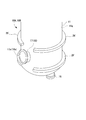
図13は、冷媒槽に備えたフランジ部の変形例を示す斜視図である。図14は、冷媒槽に備えた支持凸部の例を示す斜視図である。
図13に示すように、フランジ部(支持凸部)26’は、周方向の一部のみに設けてもよい。さらに、図14に示すように、支持凸部26”は、冷媒槽11の周方向に間隔を空けて間欠的に設け、滑車23Bやシャフト33を支持する部分にのみ、ブロック状に設けてもよい。
このような、図13、図14に示した冷媒槽11に対しても、上記第一、第二実施形態で示した共振周波数調整機構20A,20Bを備えることができる。
この発明は、上述した実施形態に限定されるものではなく、この発明の趣旨を逸脱しない範囲において、上述した実施形態に種々の変更を加えたものを含む。すなわち、実施形態で挙げた具体的な形状や構成等は一例にすぎず、適宜変更が可能である。
例えば、上記第一、第二実施形態においては、共振周波数調整機構20A、20Bの上下にフランジ部26を備えるようにし、各フランジ部26は、冷媒槽11の周方向の全周にわたって連続するものとしたがこれに限らない。
図13は、冷媒槽に備えたフランジ部の変形例を示す斜視図である。図14は、冷媒槽に備えた支持凸部の例を示す斜視図である。
図13に示すように、フランジ部(支持凸部)26’は、周方向の一部のみに設けてもよい。さらに、図14に示すように、支持凸部26”は、冷媒槽11の周方向に間隔を空けて間欠的に設け、滑車23Bやシャフト33を支持する部分にのみ、ブロック状に設けてもよい。
このような、図13、図14に示した冷媒槽11に対しても、上記第一、第二実施形態で示した共振周波数調整機構20A,20Bを備えることができる。
さらに、上記第一、第二実施形態においては、共振周波数調整機構20A、20Bを、同軸1/4波長型の超伝導加速器10A,10Bに備えるようにしたが、これに限らない。
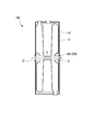
図15に示すように、1/2波長型の超伝導加速器10Cにも、同様に、加速空洞12Cの、荷電粒子ビームBの粒子流路方向両端部を挟み込むように、共振周波数調整機構20A,20Bを設けることができる。
図15に示すように、1/2波長型の超伝導加速器10Cにも、同様に、加速空洞12Cの、荷電粒子ビームBの粒子流路方向両端部を挟み込むように、共振周波数調整機構20A,20Bを設けることができる。
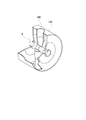
さらに、図16、図17に示すように、スポーク型の超伝導加速器10Dにおいても、同様に、加速空洞12Dの、荷電粒子ビームBの粒子流路方向両端部を挟み込むように、共振周波数調整機構20A,20Bを設けることができる。
さらに、図17中に二点鎖線で示すように、スポーク型の超伝導加速器10Dの場合、加速空洞12Dの、荷電粒子ビームBの粒子流路方向両端部を挟み込むように、共振周波数調整機構20A,20Bで押圧するのではなく、加速空洞12Dを、荷電粒子ビームBの粒子流路方向に直交する径方向両端部で押圧するように、共振周波数調整機構20A,20Bを設けてもよい。さらに、荷電粒子ビームBの粒子流路方向に直交する径方向両端部から押圧する共振周波数調整機構20A,20Bと、荷電粒子ビームBの粒子流路方向両端部の両方から押圧する共振周波数調整機構20A,20Bと、を併用するようにしても良い。
さらに、図17中に二点鎖線で示すように、スポーク型の超伝導加速器10Dの場合、加速空洞12Dの、荷電粒子ビームBの粒子流路方向両端部を挟み込むように、共振周波数調整機構20A,20Bで押圧するのではなく、加速空洞12Dを、荷電粒子ビームBの粒子流路方向に直交する径方向両端部で押圧するように、共振周波数調整機構20A,20Bを設けてもよい。さらに、荷電粒子ビームBの粒子流路方向に直交する径方向両端部から押圧する共振周波数調整機構20A,20Bと、荷電粒子ビームBの粒子流路方向両端部の両方から押圧する共振周波数調整機構20A,20Bと、を併用するようにしても良い。
さらに、図18に示すように、荷電粒子ビームBのビーム軸方向において縮径と拡径とを繰り返す加速空洞12Eを有した超伝導加速器10Dにおいても、加速空洞12Eの各セル12cを、荷電粒子ビームBの粒子流路方向に直交する径方向両端部で挟み込むように押圧する、共振周波数調整機構20A,20Bを設けてもよい。
10A~10D 超伝導加速器
11 冷媒槽
11a 上端面
11b 下端面
11f 内周面
11g 外周面
12、12C、12D、12E 加速空洞
12c セル
12f 外周面
13 ステム
13c 環状流路
14 冷媒供給口
15 接続口
16 入力結合部
17 ビーム導入管
17a 端部
18 ビーム導出管
18a 端部
19 ビーム流通管部
20A、20B 共振周波数調整機構
21 押圧部材
21a 上端部
21b 下端部
21h 開口部
22 ワイヤー(張力部材)
22A ワイヤー
22a 端部
23A、23B 滑車
23c 回転軸
24 ブラケット
25 張力調整部
26、26’ フランジ部(支持凸部)
26” 支持凸部
27 ケーブル保持プレート
27a 上端部
27b 下端部
27h ネジ挿通孔
27n 孔
28 間隔調整部材
29 ボルト
29a 頭部
29b 軸部
29g ウォームギヤ
29P 圧電素子
31 押圧部材
32A、32B、32C アーム
32a 第一端部
32b 第二端部
32c 中間部
32d ブラケット部
32e 第二端部
33 シャフト(支持軸)
35A アーム変位部
37A、37B プッシュアーム
37d ブラケット部
37p ピン
37s 第一端部
37t 第二端部
37v 第一端部
37w 第二端部
38 間隔調整部材
39 ボルト
39g ウォームギヤ
40A 押圧プレート
40B 押圧プレート
40C 連結プレート
40a 端部
40b 中央部
40p ヒンジピン
40s 両端部
A 空間
B 荷電粒子ビーム
C 中心軸
G ビーム加速ギャップ
S 隙間
11 冷媒槽
11a 上端面
11b 下端面
11f 内周面
11g 外周面
12、12C、12D、12E 加速空洞
12c セル
12f 外周面
13 ステム
13c 環状流路
14 冷媒供給口
15 接続口
16 入力結合部
17 ビーム導入管
17a 端部
18 ビーム導出管
18a 端部
19 ビーム流通管部
20A、20B 共振周波数調整機構
21 押圧部材
21a 上端部
21b 下端部
21h 開口部
22 ワイヤー(張力部材)
22A ワイヤー
22a 端部
23A、23B 滑車
23c 回転軸
24 ブラケット
25 張力調整部
26、26’ フランジ部(支持凸部)
26” 支持凸部
27 ケーブル保持プレート
27a 上端部
27b 下端部
27h ネジ挿通孔
27n 孔
28 間隔調整部材
29 ボルト
29a 頭部
29b 軸部
29g ウォームギヤ
29P 圧電素子
31 押圧部材
32A、32B、32C アーム
32a 第一端部
32b 第二端部
32c 中間部
32d ブラケット部
32e 第二端部
33 シャフト(支持軸)
35A アーム変位部
37A、37B プッシュアーム
37d ブラケット部
37p ピン
37s 第一端部
37t 第二端部
37v 第一端部
37w 第二端部
38 間隔調整部材
39 ボルト
39g ウォームギヤ
40A 押圧プレート
40B 押圧プレート
40C 連結プレート
40a 端部
40b 中央部
40p ヒンジピン
40s 両端部
A 空間
B 荷電粒子ビーム
C 中心軸
G ビーム加速ギャップ
S 隙間
Claims (9)
- 超伝導状態で荷電粒子ビームを加速する空間を形成する加速空洞と、
前記加速空洞の外周側に配置され、前記加速空洞との隙間に前記加速空洞を冷却する冷媒が充填される冷媒槽と、
前記冷媒槽の外周部に設けられ、前記加速空洞における前記荷電粒子ビームのビーム軸方向の両端部、または前記ビーム軸方向に直交する方向の両端部にそれぞれ設けられた一対の押圧部材と、
前記冷媒槽の外周部に連続して設けられ、一対の前記押圧部材同士を接近させる方向の張力を発生する張力部材と、
前記張力部材で発生する前記張力を調整する張力調整部と、
を備える超伝導加速器。 - 前記張力部材はワイヤーであり、
前記冷媒槽の外周部に周方向に間隔を空けて、前記ワイヤーが掛止される複数の滑車を備える請求項1に記載の超伝導加速器。 - 前記冷媒槽の外周部に、前記冷媒槽の外周部から外周側に突出し、前記滑車を回転自在に支持する支持凸部が設けられている請求項2に記載の超伝導加速器。
- 前記支持凸部は、前記冷媒槽の前記外周部に沿って、周方向に連続して形成されている請求項3に記載の超伝導加速器。
- 前記押圧部材に、前記滑車が設けられている請求項2から4の何れか一項に記載の超伝導加速器。
- 超伝導状態で荷電粒子ビームを加速する空間を形成する加速空洞と、
前記加速空洞の外周側に配置され、前記加速空洞との隙間に前記加速空洞を冷却する冷媒が充填される冷媒槽と、
前記冷媒槽の外周部に設けられ、前記加速空洞における前記荷電粒子ビームのビーム軸方向の両端部、または前記ビーム軸方向に直交する方向の両方の端部にそれぞれ配され、前記冷媒槽の外周部に設けられた支持軸回りに揺動自在に支持されるとともに、第一端部が前記端部に対向して設けられた一対のアームと、
一対の前記アームの第二端部同士を離間させる方向に変位させることによって、前記アームの前記第一端部で前記端部を押圧させるアーム変位部と、
を備える超伝導加速器。 - 前記アームは、前記加速空洞における前記荷電粒子ビームのビーム軸方向の両端部、または、前記ビーム軸方向に直交する方向の両端部から、前記冷媒槽の周方向の両側に延びる請求項6に記載の超伝導加速器。
- 前記冷媒槽の外周部に、前記冷媒槽の外周部から外周側に突出し、前記支持軸を支持する支持凸部が設けられている請求項6又は7に記載の超伝導加速器。
- 前記支持凸部は、前記冷媒槽の前記外周部に沿って、周方向に連続して形成されている請求項8に記載の超伝導加速器。
Priority Applications (4)
| Application Number | Priority Date | Filing Date | Title |
|---|---|---|---|
| KR1020177015667A KR101848220B1 (ko) | 2015-06-30 | 2016-02-18 | 초전도 가속기 |
| US15/739,141 US10383204B2 (en) | 2015-06-30 | 2016-02-18 | Superconducting accelerator |
| EP16817499.3A EP3319404B1 (en) | 2015-06-30 | 2016-02-18 | Superconducting accelerator with improved tuner |
| CN201680005568.XA CN107211524B (zh) | 2015-06-30 | 2016-02-18 | 超导加速器 |
Applications Claiming Priority (2)
| Application Number | Priority Date | Filing Date | Title |
|---|---|---|---|
| JP2015-131089 | 2015-06-30 | ||
| JP2015131089A JP5985011B1 (ja) | 2015-06-30 | 2015-06-30 | 超伝導加速器 |
Publications (1)
| Publication Number | Publication Date |
|---|---|
| WO2017002389A1 true WO2017002389A1 (ja) | 2017-01-05 |
Family
ID=56843270
Family Applications (1)
| Application Number | Title | Priority Date | Filing Date |
|---|---|---|---|
| PCT/JP2016/054710 Ceased WO2017002389A1 (ja) | 2015-06-30 | 2016-02-18 | 超伝導加速器 |
Country Status (6)
| Country | Link |
|---|---|
| US (1) | US10383204B2 (ja) |
| EP (1) | EP3319404B1 (ja) |
| JP (1) | JP5985011B1 (ja) |
| KR (1) | KR101848220B1 (ja) |
| CN (1) | CN107211524B (ja) |
| WO (1) | WO2017002389A1 (ja) |
Families Citing this family (5)
| Publication number | Priority date | Publication date | Assignee | Title |
|---|---|---|---|---|
| JP5985011B1 (ja) * | 2015-06-30 | 2016-09-06 | 三菱重工メカトロシステムズ株式会社 | 超伝導加速器 |
| JP6800607B2 (ja) * | 2016-05-06 | 2020-12-16 | 三菱重工機械システム株式会社 | 加速空洞、加速器及び加速空洞の共振周波数調整方法 |
| KR20200059682A (ko) | 2018-11-21 | 2020-05-29 | 고려대학교 세종산학협력단 | 멀티팩팅 효과를 최소화시킨 단일 스포크 가속관 장치 |
| JP7550702B2 (ja) | 2021-04-06 | 2024-09-13 | 三菱電機株式会社 | 加速空洞 |
| CN113260132B (zh) * | 2021-06-02 | 2025-06-03 | 中国科学院高能物理研究所 | 一种双轮辐柱轮辐超导腔及其制造方法 |
Citations (4)
| Publication number | Priority date | Publication date | Assignee | Title |
|---|---|---|---|---|
| JPH0315199A (ja) * | 1989-06-12 | 1991-01-23 | Mitsubishi Electric Corp | 超電導高周波加速空洞 |
| JPH08330098A (ja) * | 1995-06-05 | 1996-12-13 | Mitsubishi Electric Corp | 超伝導加速空洞位相調整システムとその空洞セルの共振周波数の修正方法 |
| JPH104000A (ja) * | 1996-06-12 | 1998-01-06 | Toshiba Corp | 超電導線形加速器 |
| JP2013044262A (ja) * | 2011-08-23 | 2013-03-04 | Arai Seisakusho Co Ltd | ジョイント部材 |
Family Cites Families (23)
| Publication number | Priority date | Publication date | Assignee | Title |
|---|---|---|---|---|
| JP2568001B2 (ja) * | 1991-05-24 | 1996-12-25 | 株式会社東芝 | 真空ダクトの支持装置 |
| JPH0513032A (ja) | 1991-06-28 | 1993-01-22 | Ulvac Japan Ltd | イオンビーム形成装置におけるスリツト調節装置 |
| JPH0954807A (ja) * | 1995-08-18 | 1997-02-25 | Nippon Avionics Co Ltd | 搬送ルート自動決定システム |
| JPH1120742A (ja) * | 1997-07-02 | 1999-01-26 | Kanto Auto Works Ltd | 開閉部材のヒンジ緩衝体 |
| US6657515B2 (en) | 2001-06-18 | 2003-12-02 | Energen, Llp | Tuning mechanism for a superconducting radio frequency particle accelerator cavity |
| JP4444222B2 (ja) * | 2005-04-12 | 2010-03-31 | 三菱重工業株式会社 | 超伝導加速空洞の製造方法 |
| JP2010277942A (ja) * | 2009-06-01 | 2010-12-09 | Mitsubishi Electric Corp | Hモード型ドリフトチューブ線形加速器、およびその電場分布調整方法 |
| JP5409186B2 (ja) * | 2009-08-17 | 2014-02-05 | 三菱重工業株式会社 | 超伝導加速空洞の製造方法 |
| JP2011167709A (ja) * | 2010-02-17 | 2011-09-01 | Mitsubishi Heavy Ind Ltd | 溶接方法および超伝導加速器 |
| JP5489830B2 (ja) * | 2010-04-09 | 2014-05-14 | 三菱重工業株式会社 | 外導体製造方法 |
| JP5595114B2 (ja) * | 2010-05-12 | 2014-09-24 | 三菱重工業株式会社 | 超伝導加速空洞の製造方法 |
| JP5449019B2 (ja) * | 2010-05-12 | 2014-03-19 | 三菱重工業株式会社 | 超伝導加速空洞および超伝導加速空洞の製造方法 |
| JP5781278B2 (ja) * | 2010-05-14 | 2015-09-16 | 三菱重工業株式会社 | 溶接装置 |
| JP5523964B2 (ja) * | 2010-07-21 | 2014-06-18 | 三菱重工業株式会社 | 超伝導加速空洞の共振周波数調整装置 |
| JP5449093B2 (ja) * | 2010-09-03 | 2014-03-19 | 三菱重工業株式会社 | 超伝導加速空洞のポート部材 |
| JP5804840B2 (ja) * | 2011-08-11 | 2015-11-04 | 三菱重工業株式会社 | 加工装置及び加工方法 |
| RU2606647C2 (ru) | 2012-06-20 | 2017-01-10 | Фудзи Сейко Ко., Лтд. | Устройство намотки скрепляющей нити бортового кольца |
| JP6037741B2 (ja) * | 2012-09-18 | 2016-12-07 | 三菱重工工作機械株式会社 | 移動型真空溶接装置 |
| JP6214909B2 (ja) * | 2013-04-19 | 2017-10-18 | 住友重機械工業株式会社 | 超電導磁石 |
| JP6049601B2 (ja) * | 2013-12-05 | 2016-12-21 | 三菱重工メカトロシステムズ株式会社 | 超伝導加速空洞、および超伝導加速空洞の電解研磨方法 |
| JP6523047B2 (ja) * | 2015-05-29 | 2019-05-29 | 三菱重工機械システム株式会社 | シールド体、及び超伝導加速器 |
| JP5985011B1 (ja) * | 2015-06-30 | 2016-09-06 | 三菱重工メカトロシステムズ株式会社 | 超伝導加速器 |
| JP7095480B2 (ja) * | 2018-08-14 | 2022-07-05 | マックス株式会社 | 送風装置、及び取付枠体 |
-
2015
- 2015-06-30 JP JP2015131089A patent/JP5985011B1/ja active Active
-
2016
- 2016-02-18 KR KR1020177015667A patent/KR101848220B1/ko active Active
- 2016-02-18 EP EP16817499.3A patent/EP3319404B1/en active Active
- 2016-02-18 WO PCT/JP2016/054710 patent/WO2017002389A1/ja not_active Ceased
- 2016-02-18 CN CN201680005568.XA patent/CN107211524B/zh active Active
- 2016-02-18 US US15/739,141 patent/US10383204B2/en active Active
Patent Citations (4)
| Publication number | Priority date | Publication date | Assignee | Title |
|---|---|---|---|---|
| JPH0315199A (ja) * | 1989-06-12 | 1991-01-23 | Mitsubishi Electric Corp | 超電導高周波加速空洞 |
| JPH08330098A (ja) * | 1995-06-05 | 1996-12-13 | Mitsubishi Electric Corp | 超伝導加速空洞位相調整システムとその空洞セルの共振周波数の修正方法 |
| JPH104000A (ja) * | 1996-06-12 | 1998-01-06 | Toshiba Corp | 超電導線形加速器 |
| JP2013044262A (ja) * | 2011-08-23 | 2013-03-04 | Arai Seisakusho Co Ltd | ジョイント部材 |
Also Published As
| Publication number | Publication date |
|---|---|
| KR101848220B1 (ko) | 2018-04-11 |
| JP5985011B1 (ja) | 2016-09-06 |
| EP3319404A4 (en) | 2019-03-06 |
| US10383204B2 (en) | 2019-08-13 |
| EP3319404A1 (en) | 2018-05-09 |
| EP3319404B1 (en) | 2020-04-22 |
| JP2017016835A (ja) | 2017-01-19 |
| CN107211524B (zh) | 2019-03-22 |
| CN107211524A (zh) | 2017-09-26 |
| KR20170077246A (ko) | 2017-07-05 |
| US20190090342A1 (en) | 2019-03-21 |
Similar Documents
| Publication | Publication Date | Title |
|---|---|---|
| JP5985011B1 (ja) | 超伝導加速器 | |
| JP5759177B2 (ja) | プラズマ処理装置、半導体基板を処理する方法、および軸直角変位ベローズユニット | |
| KR102097436B1 (ko) | 표면파 플라즈마 장치 | |
| KR101711713B1 (ko) | 마이크로파 방사 기구, 마이크로파 플라즈마원 및 표면파 플라즈마 처리 장치 | |
| KR101997308B1 (ko) | 진공 펌프용 어댑터 및 관련 펌핑 장치 | |
| US8952775B2 (en) | Superconductive magnet | |
| US11948776B2 (en) | Plasma processing apparatus | |
| CN102543223B (zh) | 一种法拉第屏蔽冷却管可调角度的icrf天线结构 | |
| KR101697580B1 (ko) | 진공 인터럽터 | |
| US5245157A (en) | Microwave plasma processing or semiconductor devices | |
| US20140125254A1 (en) | Accelerating structure | |
| CN113593728A (zh) | 一种适用于超高真空及强磁场条件下的光学镜调节机构 | |
| CN109362171B (zh) | 一种谐振腔频率自动调谐装置 | |
| KR20180127438A (ko) | 가속 공동, 가속기 및 가속 공동의 공진 주파수 조정 방법 | |
| Pan et al. | Integration and horizontal testing of the CSNS-II double-spoke cavity cryomodule: W.-M. Pan et al. | |
| US12523722B2 (en) | Rotor cap removing tools, microwave guides, and methods | |
| JP2008182713A (ja) | マイクロ波アンテナ及びマイクロ波プラズマ処理装置 | |
| KR20210014934A (ko) | 가속관용 고출력 입력커플러 | |
| JP2012028090A (ja) | 超伝導加速空洞の共振周波数調整装置 | |
| EP3005386B1 (en) | Vacuum variable capacitor | |
| JP2013251240A (ja) | イオンビーム照射装置 | |
| JP3230945B2 (ja) | イオン源及びイオン注入装置 | |
| JPH10107011A (ja) | プラズマ処理装置 | |
| JP2014012875A (ja) | プラズマ処理装置 | |
| US20160343529A1 (en) | Gas circuit breaker |
Legal Events
| Date | Code | Title | Description |
|---|---|---|---|
| 121 | Ep: the epo has been informed by wipo that ep was designated in this application |
Ref document number: 16817499 Country of ref document: EP Kind code of ref document: A1 |
|
| ENP | Entry into the national phase |
Ref document number: 20177015667 Country of ref document: KR Kind code of ref document: A |
|
| NENP | Non-entry into the national phase |
Ref country code: DE |
|
| WWE | Wipo information: entry into national phase |
Ref document number: 2016817499 Country of ref document: EP |