WO2017002453A1 - Dispositif de frein électromécanique - Google Patents
Dispositif de frein électromécanique Download PDFInfo
- Publication number
- WO2017002453A1 WO2017002453A1 PCT/JP2016/063811 JP2016063811W WO2017002453A1 WO 2017002453 A1 WO2017002453 A1 WO 2017002453A1 JP 2016063811 W JP2016063811 W JP 2016063811W WO 2017002453 A1 WO2017002453 A1 WO 2017002453A1
- Authority
- WO
- WIPO (PCT)
- Prior art keywords
- control unit
- brake
- brake mechanism
- braking force
- wheel
- Prior art date
- Legal status (The legal status is an assumption and is not a legal conclusion. Google has not performed a legal analysis and makes no representation as to the accuracy of the status listed.)
- Ceased
Links
Images





Classifications
-
- B—PERFORMING OPERATIONS; TRANSPORTING
- B60—VEHICLES IN GENERAL
- B60T—VEHICLE BRAKE CONTROL SYSTEMS OR PARTS THEREOF; BRAKE CONTROL SYSTEMS OR PARTS THEREOF, IN GENERAL; ARRANGEMENT OF BRAKING ELEMENTS ON VEHICLES IN GENERAL; PORTABLE DEVICES FOR PREVENTING UNWANTED MOVEMENT OF VEHICLES; VEHICLE MODIFICATIONS TO FACILITATE COOLING OF BRAKES
- B60T8/00—Arrangements for adjusting wheel-braking force to meet varying vehicular or ground-surface conditions, e.g. limiting or varying distribution of braking force
- B60T8/17—Using electrical or electronic regulation means to control braking
-
- B—PERFORMING OPERATIONS; TRANSPORTING
- B60—VEHICLES IN GENERAL
- B60T—VEHICLE BRAKE CONTROL SYSTEMS OR PARTS THEREOF; BRAKE CONTROL SYSTEMS OR PARTS THEREOF, IN GENERAL; ARRANGEMENT OF BRAKING ELEMENTS ON VEHICLES IN GENERAL; PORTABLE DEVICES FOR PREVENTING UNWANTED MOVEMENT OF VEHICLES; VEHICLE MODIFICATIONS TO FACILITATE COOLING OF BRAKES
- B60T13/00—Transmitting braking action from initiating means to ultimate brake actuator with power assistance or drive; Brake systems incorporating such transmitting means, e.g. air-pressure brake systems
- B60T13/74—Transmitting braking action from initiating means to ultimate brake actuator with power assistance or drive; Brake systems incorporating such transmitting means, e.g. air-pressure brake systems with electrical assistance or drive
- B60T13/741—Transmitting braking action from initiating means to ultimate brake actuator with power assistance or drive; Brake systems incorporating such transmitting means, e.g. air-pressure brake systems with electrical assistance or drive acting on an ultimate actuator
-
- B—PERFORMING OPERATIONS; TRANSPORTING
- B60—VEHICLES IN GENERAL
- B60T—VEHICLE BRAKE CONTROL SYSTEMS OR PARTS THEREOF; BRAKE CONTROL SYSTEMS OR PARTS THEREOF, IN GENERAL; ARRANGEMENT OF BRAKING ELEMENTS ON VEHICLES IN GENERAL; PORTABLE DEVICES FOR PREVENTING UNWANTED MOVEMENT OF VEHICLES; VEHICLE MODIFICATIONS TO FACILITATE COOLING OF BRAKES
- B60T7/00—Brake-action initiating means
- B60T7/02—Brake-action initiating means for personal initiation
- B60T7/04—Brake-action initiating means for personal initiation foot actuated
- B60T7/042—Brake-action initiating means for personal initiation foot actuated by electrical means, e.g. using travel or force sensors
-
- B—PERFORMING OPERATIONS; TRANSPORTING
- B60—VEHICLES IN GENERAL
- B60T—VEHICLE BRAKE CONTROL SYSTEMS OR PARTS THEREOF; BRAKE CONTROL SYSTEMS OR PARTS THEREOF, IN GENERAL; ARRANGEMENT OF BRAKING ELEMENTS ON VEHICLES IN GENERAL; PORTABLE DEVICES FOR PREVENTING UNWANTED MOVEMENT OF VEHICLES; VEHICLE MODIFICATIONS TO FACILITATE COOLING OF BRAKES
- B60T7/00—Brake-action initiating means
- B60T7/02—Brake-action initiating means for personal initiation
- B60T7/08—Brake-action initiating means for personal initiation hand actuated
- B60T7/10—Disposition of hand control
- B60T7/107—Disposition of hand control with electrical power assistance
-
- B—PERFORMING OPERATIONS; TRANSPORTING
- B60—VEHICLES IN GENERAL
- B60T—VEHICLE BRAKE CONTROL SYSTEMS OR PARTS THEREOF; BRAKE CONTROL SYSTEMS OR PARTS THEREOF, IN GENERAL; ARRANGEMENT OF BRAKING ELEMENTS ON VEHICLES IN GENERAL; PORTABLE DEVICES FOR PREVENTING UNWANTED MOVEMENT OF VEHICLES; VEHICLE MODIFICATIONS TO FACILITATE COOLING OF BRAKES
- B60T7/00—Brake-action initiating means
- B60T7/12—Brake-action initiating means for automatic initiation; for initiation not subject to will of driver or passenger
-
- B—PERFORMING OPERATIONS; TRANSPORTING
- B60—VEHICLES IN GENERAL
- B60T—VEHICLE BRAKE CONTROL SYSTEMS OR PARTS THEREOF; BRAKE CONTROL SYSTEMS OR PARTS THEREOF, IN GENERAL; ARRANGEMENT OF BRAKING ELEMENTS ON VEHICLES IN GENERAL; PORTABLE DEVICES FOR PREVENTING UNWANTED MOVEMENT OF VEHICLES; VEHICLE MODIFICATIONS TO FACILITATE COOLING OF BRAKES
- B60T8/00—Arrangements for adjusting wheel-braking force to meet varying vehicular or ground-surface conditions, e.g. limiting or varying distribution of braking force
- B60T8/17—Using electrical or electronic regulation means to control braking
- B60T8/176—Brake regulation specially adapted to prevent excessive wheel slip during vehicle deceleration, e.g. ABS
- B60T8/1766—Proportioning of brake forces according to vehicle axle loads, e.g. front to rear of vehicle
-
- B—PERFORMING OPERATIONS; TRANSPORTING
- B60—VEHICLES IN GENERAL
- B60T—VEHICLE BRAKE CONTROL SYSTEMS OR PARTS THEREOF; BRAKE CONTROL SYSTEMS OR PARTS THEREOF, IN GENERAL; ARRANGEMENT OF BRAKING ELEMENTS ON VEHICLES IN GENERAL; PORTABLE DEVICES FOR PREVENTING UNWANTED MOVEMENT OF VEHICLES; VEHICLE MODIFICATIONS TO FACILITATE COOLING OF BRAKES
- B60T8/00—Arrangements for adjusting wheel-braking force to meet varying vehicular or ground-surface conditions, e.g. limiting or varying distribution of braking force
- B60T8/32—Arrangements for adjusting wheel-braking force to meet varying vehicular or ground-surface conditions, e.g. limiting or varying distribution of braking force responsive to a speed condition, e.g. acceleration or deceleration
- B60T8/88—Arrangements for adjusting wheel-braking force to meet varying vehicular or ground-surface conditions, e.g. limiting or varying distribution of braking force responsive to a speed condition, e.g. acceleration or deceleration with failure responsive means, i.e. means for detecting and indicating faulty operation of the speed responsive control means
- B60T8/885—Arrangements for adjusting wheel-braking force to meet varying vehicular or ground-surface conditions, e.g. limiting or varying distribution of braking force responsive to a speed condition, e.g. acceleration or deceleration with failure responsive means, i.e. means for detecting and indicating faulty operation of the speed responsive control means using electrical circuitry
-
- F—MECHANICAL ENGINEERING; LIGHTING; HEATING; WEAPONS; BLASTING
- F16—ENGINEERING ELEMENTS AND UNITS; GENERAL MEASURES FOR PRODUCING AND MAINTAINING EFFECTIVE FUNCTIONING OF MACHINES OR INSTALLATIONS; THERMAL INSULATION IN GENERAL
- F16D—COUPLINGS FOR TRANSMITTING ROTATION; CLUTCHES; BRAKES
- F16D55/00—Brakes with substantially-radial braking surfaces pressed together in axial direction, e.g. disc brakes
- F16D55/02—Brakes with substantially-radial braking surfaces pressed together in axial direction, e.g. disc brakes with axially-movable discs or pads pressed against axially-located rotating members
- F16D55/22—Brakes with substantially-radial braking surfaces pressed together in axial direction, e.g. disc brakes with axially-movable discs or pads pressed against axially-located rotating members by clamping an axially-located rotating disc between movable braking members, e.g. movable brake discs or brake pads
- F16D55/224—Brakes with substantially-radial braking surfaces pressed together in axial direction, e.g. disc brakes with axially-movable discs or pads pressed against axially-located rotating members by clamping an axially-located rotating disc between movable braking members, e.g. movable brake discs or brake pads with a common actuating member for the braking members
- F16D55/225—Brakes with substantially-radial braking surfaces pressed together in axial direction, e.g. disc brakes with axially-movable discs or pads pressed against axially-located rotating members by clamping an axially-located rotating disc between movable braking members, e.g. movable brake discs or brake pads with a common actuating member for the braking members the braking members being brake pads
- F16D55/226—Brakes with substantially-radial braking surfaces pressed together in axial direction, e.g. disc brakes with axially-movable discs or pads pressed against axially-located rotating members by clamping an axially-located rotating disc between movable braking members, e.g. movable brake discs or brake pads with a common actuating member for the braking members the braking members being brake pads in which the common actuating member is moved axially, e.g. floating caliper disc brakes
-
- F—MECHANICAL ENGINEERING; LIGHTING; HEATING; WEAPONS; BLASTING
- F16—ENGINEERING ELEMENTS AND UNITS; GENERAL MEASURES FOR PRODUCING AND MAINTAINING EFFECTIVE FUNCTIONING OF MACHINES OR INSTALLATIONS; THERMAL INSULATION IN GENERAL
- F16D—COUPLINGS FOR TRANSMITTING ROTATION; CLUTCHES; BRAKES
- F16D65/00—Parts or details
- F16D65/14—Actuating mechanisms for brakes; Means for initiating operation at a predetermined position
- F16D65/16—Actuating mechanisms for brakes; Means for initiating operation at a predetermined position arranged in or on the brake
- F16D65/18—Actuating mechanisms for brakes; Means for initiating operation at a predetermined position arranged in or on the brake adapted for drawing members together, e.g. for disc brakes
- F16D65/183—Actuating mechanisms for brakes; Means for initiating operation at a predetermined position arranged in or on the brake adapted for drawing members together, e.g. for disc brakes with force-transmitting members arranged side by side acting on a spot type force-applying member
-
- B—PERFORMING OPERATIONS; TRANSPORTING
- B60—VEHICLES IN GENERAL
- B60T—VEHICLE BRAKE CONTROL SYSTEMS OR PARTS THEREOF; BRAKE CONTROL SYSTEMS OR PARTS THEREOF, IN GENERAL; ARRANGEMENT OF BRAKING ELEMENTS ON VEHICLES IN GENERAL; PORTABLE DEVICES FOR PREVENTING UNWANTED MOVEMENT OF VEHICLES; VEHICLE MODIFICATIONS TO FACILITATE COOLING OF BRAKES
- B60T2270/00—Further aspects of brake control systems not otherwise provided for
- B60T2270/40—Failsafe aspects of brake control systems
- B60T2270/402—Back-up
Definitions
- the present invention relates to an electric brake device that includes a frictional member that rotates together with a wheel and a frictional member that moves by power from an electric actuator, and obtains a braking force by pressing the frictional member against the frictional member.
- Patent Document 1 discloses an electric control brake including a brake that suppresses rotation of a wheel, a power source, and a brake control device that controls an operating state of the brake by controlling electric energy supplied from the power source.
- a switch device that is switched from a disconnected state to a connected state in accordance with a braking operation of the brake operation member is provided between the power source and the brake control device.
- a switching device that can be switched between a linked state in which the operation of a mechanical brake that is operated in accordance with the operation of the operating member is linked to the brake operating member, and a separated state that is separated from the brake operating member. Switching device that switches from the separated state to the linked state when the control brake system is abnormal It is disclosed to be those containing a control device.
- the present invention has been made in view of such circumstances, and an object thereof is to improve the convenience of the electric brake device.
- an electric brake device includes a first brake mechanism that brakes a first wheel, a second brake mechanism that brakes a second wheel, and a third brake mechanism. And a fourth brake mechanism for braking the fourth wheel, and at least three control units, each of the control units, When at least one of the four brake mechanisms is controlled and at least one of the three control units fails, at least one of the other non-failed control units is a brake mechanism to be controlled The braking force is reduced temporarily.
- the electric brake device when at least one of the three control units fails, one of the other non-failed control units increases the braking force of the brake mechanism to be controlled.
- the other one of the other non-failed control units temporarily reduces the braking force of the brake mechanism to be controlled, and then the one of the other non-failed control units
- the braking force of the brake mechanism to be controlled is increased in conjunction with the increase of the braking force.
- the first wheel and the second wheel are arranged at intervals in the full width direction of the vehicle
- the third wheel and the fourth wheel are The three control units are arranged at intervals in the full width direction and at intervals from the first wheel and the second wheel in the full length direction of the vehicle.
- an electric brake device comprising: a first brake pair comprising the first brake mechanism and the second brake mechanism; a third brake mechanism comprising the third brake mechanism and the fourth brake mechanism.
- An ideal braking force distribution value in the full length direction of the vehicle is set between the two brake pairs, and the other non-failing control unit temporarily applies the braking force of the brake mechanism to be controlled. The value is lower than the ideal braking force distribution value.
- each of the brake mechanisms is connected to a main battery and a backup battery serving as a power source for controlling and operating the brake mechanism, and to the brake mechanism when the main battery fails.
- the power supply source is switched to a backup battery.
- the electric brake device according to a sixth aspect of the invention is characterized in that the main battery and the backup battery preferentially supply power to a brake mechanism that brakes the front wheels of the vehicle.
- the first wheel is a left front wheel
- the second wheel is a right front wheel
- the third wheel is a left rear wheel
- the fourth wheel The wheel is a right rear wheel
- the first brake mechanism is a left front wheel brake mechanism
- the second brake mechanism is a right front wheel brake mechanism
- the third brake mechanism is a left rear wheel brake.
- the fourth brake mechanism is a right rear wheel brake mechanism
- the three control units are the first control unit, the second control unit, and the third control unit
- the first control unit is a first front wheel control unit
- the second control unit is a second front wheel control unit
- the third control unit is a rear wheel control unit. It is characterized by.
- the third control unit when at least one of the first control unit or the second control unit fails, the third control unit includes the left rear wheel brake mechanism and The braking force of the right rear wheel brake mechanism is temporarily reduced.
- At least one of the three control units fails, at least one of the non-failed control units temporarily reduces the braking force.
- the braking force of the target brake mechanism suddenly decreases, it is advantageous for maintaining the braking force distribution between the wheel pairs in an appropriate state.
- the invention of claim 2 when one control unit fails, one of the other control units that do not fail increases the braking force, and the other one of the other control units After the braking force is temporarily reduced, the braking force is increased in conjunction with the increase of the braking force by one of the other control units, so that the braking force of the entire vehicle is secured while preventing the wheels from being locked. This is advantageous.
- the controller that has not failed reduces the braking force based on the ideal braking force distribution value set for the vehicle, which is advantageous in stabilizing the vehicle posture during braking.
- the brake mechanism can be operated by the sub-battery even when the main battery fails, and the redundancy of the brake mechanism is reduced. It becomes advantageous in raising.
- the redundancy of the front wheel brake mechanism which is more important in braking the vehicle, is increased.
- two control units are assigned to the left and right front wheel brake mechanisms, and one control unit is assigned to the rear wheel brake mechanism on the left and right. Even if the vehicle breaks down, the remaining front wheel brake mechanism can be controlled, which is advantageous in increasing the redundancy of the front wheel brake, which is more important during braking.
- the control unit for controlling the rear wheel brake mechanism temporarily reduces the braking force. This is advantageous in keeping the braking force distribution of the front and rear wheels within an appropriate range when the braking force of the brake mechanism for the vehicle suddenly decreases.
- FIG. 3 is an explanatory diagram illustrating a configuration example of a parking brake in the electric brake device 10. It is explanatory drawing which shows the schematic structural example of a control part. It is explanatory drawing which shows the change of the braking force when a control part fails. It is explanatory drawing which shows the change of the braking force when a control part fails. It is explanatory drawing which shows the change of the braking force when a control part fails. It is explanatory drawing which shows the change of the braking force when a control part fails. It is explanatory drawing which shows the ideal braking force distribution characteristic of a front-and-back wheel. It is an Example of the electric brake device using four control parts.
- FIG. 1 is an explanatory view showing the composition of electric brake equipment 10 concerning an embodiment.
- the electric brake device 10 includes front, rear, left and right wheels 12, 14, 16, 18, brake mechanisms 20, 22, 24, 26, 34, 36 provided on the wheels, and control units 28, 30, 32, 38, 50 and operation units 52 and 54.
- the electric brake device 10 has a main battery 40 and a backup battery 42 (see FIG. 2) in addition to the configuration shown in FIG. 1, but is not shown in FIG.
- the wheels 12, 14, 16, 18 are the left front wheel 12, the right front wheel 14, the left rear wheel 16, and the right rear wheel 18, and the left front wheel brake mechanism 20 is connected to the left front wheel 12.
- the wheels 12, 14, 16, 18 are provided with a right front wheel brake mechanism 22, a left rear wheel 16 with a left rear wheel brake mechanism 24, and a right rear wheel 18 with a right rear wheel brake mechanism 26, which brake the respective wheels.
- Each brake mechanism 20, 22, 24, 26 implements a service brake, and is provided with control units 28, 30, 32, respectively.
- Each control unit 28, 30, 32 controls at least one of the brake mechanisms 20, 22, 24, 26.
- the left front wheel brake mechanism 20 and the right front wheel brake mechanism 22 are separated from the left rear wheel brake mechanism 24 and the right rear wheel by the first front wheel control unit 28 and the second front wheel control unit 30, respectively.
- the wheel brake mechanism 26 is controlled by the rear wheel control unit 32. That is, the first front wheel control unit 28 that is the first control unit controls the left front wheel brake mechanism 20 and the right front wheel brake mechanism 22, and the second front wheel control unit is the second control unit. 30 controls the left front wheel brake mechanism 20 and the right front wheel brake mechanism 22, and the third front wheel control unit 32, which is a third control unit, includes a left rear wheel brake mechanism 24 and a right rear wheel brake.
- the mechanism 26 is controlled.
- the parking control unit 38 controls the parking brake mechanisms 34 and 36.
- Each control unit 28, 30, 32, 38 is connected to a vehicle control unit 50 that controls the main control of the vehicle.
- the vehicle control unit 50 is connected to a brake pedal (service brake operation unit) 52 and a parking brake operation unit 54.
- a brake pedal 52 or the parking brake operation unit 54 When the brake pedal 52 or the parking brake operation unit 54 is operated, the respective control units 28 and 30 are connected. , 32, and 38, a control signal for instructing to operate the brake is output.
- the vehicle control unit 50 monitors the operating state of each control unit 28, 30, 32, 38, and when a failure occurs in any one of the control units 28, 30, 32, 38, the other control unit A control signal indicating a failure is output.
- the control units 28, 30, 32, and 38 are directly connected to monitor the operating state of each other. May be.
- Each brake mechanism 20, 22, 24, 26 includes a friction member that rotates together with the wheel and a friction member that moves by the power of the electric actuator, and applies braking force by pressing the friction member against the friction member.
- Electric calipers each having a pad (friction member). During normal (non-braking) time, the brake pad is located at a non-pressing position away from the brake disc.
- control units 28, 30, and 32 operate the electric actuator to move the brake pad to a pressing position where the brake pad comes into contact with the brake disc, thereby converting the kinetic energy of the wheels into heat energy, thereby causing the vehicle to have a desired vehicle speed To slow down.
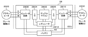
- FIG. 3 is an explanatory diagram illustrating a schematic configuration example of the control unit.
- the control units 28, 30, and 32 all control two brake mechanisms, and the configuration is the same.
- FIG. 3 shows the first front wheel controller 28.
- the first front wheel controller 28 includes a dual microcomputer 2802, two integrated circuits (ICs) 2804 and 2806, two bridge (inverter) circuits 2808 and 2810, and a power supply regulator 2812. .
- the power regulator 2812 and the respective bridge circuits 2808 and 2810 are connected to the battery 40.
- the dual microcomputer 2802 is connected to the vehicle control unit 50 (not shown in FIG. 3). When a brake operation instruction is output from the vehicle control unit 50, the dual microcomputer 2802 drives the bridge circuits 2808 and 2810 to drive the battery.
- the electric power of 40 is converted into three-phase alternating current and supplied to the electric actuators 2002 and 2202 of the brake mechanism (the left front wheel brake mechanism 20 and the right front wheel brake mechanism 22 in FIG. 3) to drive the electric actuators 2002 and 2202. That is, the first front wheel control unit 28 includes a power circuit for the left front wheel brake mechanism 20 and the right front wheel brake mechanism 22. Since the operations of the bridge circuits 2808 and 2810 can be independently controlled, the electric actuators 2002 and 2202 (the left front wheel brake mechanism 20 and the right front wheel brake mechanism 22) can be independently operated. Become. As described above, the left front wheel brake mechanism 20 and the right front wheel brake mechanism 22 are controlled by the first front wheel control unit 28 and the second front wheel control unit 30.
- Electric power required by the brake mechanism 20 for the front and the brake mechanism 22 for the right front wheel is supplied by the first front wheel control unit 28 and the second front wheel control unit 30 by half.
- the operation of the brake mechanism is controlled by an electric signal, so that the operation of the brake mechanism can be finely controlled according to the situation, and hydraulic piping or the like is not required, and the vehicle weight can be significantly reduced.
- each brake mechanism 20, 22, 24, 26 is connected to the main battery 40 and the backup battery 42, and when the main battery 40 breaks down, each brake mechanism 20, The power source of the power supplies 22, 24, and 26 is configured to be switched to the backup battery 42. Thereby, the availability of the brake mechanisms 20, 22, 24, and 26 can be improved.
- the main battery 40 and the backup battery 42 are configured to supply power to the left and right front wheel brake mechanisms 20 and 22 preferentially.
- the left rear wheel 16 and the right rear wheel 18 are further provided with parking brake mechanisms 34 and 36, respectively.
- the parking brake mechanisms 34 and 36 are mainly used for preventing the vehicle from moving during parking.
- the parking brake mechanisms 34 and 36 are controlled by a parking control unit 38.
- the parking brake mechanisms 34 and 36 are electric parking brakes (EPB), and there are a plurality of configurations.
- FIG. 2 is an explanatory diagram illustrating a configuration example of a parking brake in the electric brake device 10.
- EMB 20 corresponds to the left front wheel brake mechanism
- EMB 22 corresponds to the right front wheel brake mechanism
- EMB 24 corresponds to the left rear wheel brake mechanism
- EMB 26 corresponds to the right rear wheel brake mechanism 26.
- the ECU 28 corresponds to the first front wheel control unit 28
- the ECU 30 corresponds to the second front wheel control unit
- the ECU 32 corresponds to the rear wheel control unit 32.
- the EPB 38 corresponds to the parking control unit 38.
- the left rear wheel brake mechanism 24 and the right rear wheel brake mechanism 26 serve as the parking brake mechanisms 34 and 36. That is, the parking control unit 38 operates the electric actuators of the left rear wheel brake mechanism 24 and the right rear wheel brake mechanism 26 when the parking brake is operated, and moves the brake pad to the position pressed against the brake disc. A braking force is applied to the left and right rear wheels 16,18. According to such a configuration, a parking-dedicated brake mechanism is not required, and the vehicle can be reduced in weight.
- FIG. 2B shows an example in which the parking brake mechanisms 34 and 36 are configured by a drum-in-hat (DIH) system in which brake drums are arranged in the brake discs of the left rear wheel brake mechanism 24 and the right rear wheel brake mechanism 26. is there. That is, the parking brake mechanisms 34 and 36 are provided in the hat portions located at the center of the brake pads of the left rear wheel brake mechanism 24 and the right rear wheel brake mechanism 26, respectively, And a brake shoe that is provided in the brake drum and moves between a pressed position and a non-pressed position with respect to the brake drum by an electric actuator for parking.
- DIH drum-in-hat
- the brake shoe is biased by the spring toward the inner periphery of the brake drum and is in a non-pressing position away from the brake drum.
- a brake shoe lever having one end attached to the brake shoe so as to be swingable and a wire attached to the other end is attached to the brake shoe.
- the brake shoe lever swings, the brake shoe moves against the biasing force of the spring, moves toward the outer periphery of the brake drum, and is positioned at the position pressed against the brake drum.
- the parking control unit 38 operates the parking electric actuator when the parking brake is operated, and moves the brake shoes of the parking brake mechanisms 34 and 36 to the pressing position against the brake drum 16 to thereby change the left and right rear wheels 16. , 18 is applied with a braking force.
- FIG. 2C shows an example in which brake drum type electric parking brake mechanisms 34 and 36 are configured in the brake discs of the left rear wheel brake mechanism 24 and the right rear wheel brake mechanism 26. That is, the parking brake mechanisms 34, 36 are provided in the hat portions located at the center of the brake pads of the left rear wheel brake mechanism 24 and the right rear wheel brake mechanism 26, respectively, And a brake shoe that is provided in the brake disc and moves between a pressed position and a non-pressed position with respect to the brake disc by an electric actuator for parking. Further, the parking control unit 38 is configured integrally with the parking brake mechanisms 34 and 36. During normal operation (during non-parking braking), the brake shoe is biased toward the inner periphery of the brake disc and is in a non-pressing position away from the brake disc.
- a motor having a linear motion mechanism is attached between one end of the brake shoe and one end of the brake shoe.
- the drum parking motor rotates, it pushes one end of the brake shoe through the linear motion mechanism.
- the brake shoe moves toward the outer periphery of the brake disc and is positioned at a position where the brake disc is pressed.
- the parking control unit 38 operates the parking electric actuator when the parking brake is operated, and moves the brake shoes of the parking brake mechanisms 34 and 36 to the pressing position against the brake drum 16 to thereby change the left and right rear wheels 16. , 18 is applied with a braking force.
- the electric brake device 10 controls the four brake mechanisms 20, 22, 24, 26 provided on the four wheels 12, 14, 16, 18 with the three control units 28, 30, 32. If the two control units fail, the three wheels cannot be braked, and there is a possibility that the spin will occur. For this reason, in the electric brake device 10, when any of the left front wheel, the right front wheel, the left rear wheel, and the right rear wheel is braked, any one of the three control units 28, 30, and 32 is selected. Even if one or two malfunctions, at least two wheels can be braked to ensure the steering performance of the vehicle and the braking force necessary to stop the vehicle.
- the failure of the control units 28, 30, and 32 refers to a state in which the brake mechanisms 20, 22, 24, and 26 cannot be operated, and examples include failure of a power supply circuit and disconnection of a signal line.
- the ECU 1 is in the first front wheel control unit 28, the ECU 2 is in the second front wheel control unit 30, the ECU 3 is in the rear wheel control unit 32, and the EPB is in the parking control unit 38.
- the control unit increases (or decreases) the braking force of the brake mechanism means, for example, that the power supplied from the control unit is increased (or reduced), for example, from the control unit to the brake mechanism. It indicates the magnitude of the control value, and does not necessarily indicate the braking force of the entire brake mechanism.
- the brake mechanism when the brake mechanism is controlled by a plurality of control units, even when one control unit increases the braking force of the brake mechanism, the brake mechanism as a whole is caused by factors such as failure of another control unit. In some cases, the braking force does not increase.
- the first front wheel control unit 28 and the second front wheel control unit 30 both have a predetermined braking force P1.
- the left and right front wheel brake mechanisms 20 and 22 are driven so as to be generated. That is, the left and right front wheel brake mechanisms 20 and 22 collectively generate a braking force of P1 ⁇ 2.
- the rear wheel control unit 32 (ECU 3) drives the left and right rear wheel brake mechanisms 24 and 26 so as to generate a predetermined braking force P2 ( ⁇ P1).
- the total braking force by the three controllers 28, 30, and 32 is P3.
- the first front wheel control unit 28 (ECU1) breaks down at time T1
- the power supply from the first front wheel control unit 28 to the left and right front wheel brake mechanisms 20, 22 is lost, and the second front wheel control unit Only power from 30 is supplied. Therefore, the total braking force of the left and right front wheel brake mechanisms 20, 22 is halved to P1 ⁇ 1.
- the second front wheel control unit 30 (ECU 2) increases the amount of power supplied to the left and right front wheel brake mechanisms 20, 22, so that the left and right front wheel brake mechanisms 20, 22 are more than P1 ⁇ 1. A large braking force P4 is generated.
- the rear wheel control unit 32 reduces the amount of power supplied to the left and right rear wheel brake mechanisms 24 and 26 immediately after the failure of the first front wheel control unit 28, thereby The braking force is reduced to the braking force P5 ( ⁇ P2) of the brake mechanisms 24 and 26. That is, when at least one of the three control units 28, 30, and 32 fails, at least one of the other non-failed control units (in this case, the rear wheel control unit 32) is a brake mechanism to be controlled. The braking force is temporarily reduced. This is to prevent the left and right rear wheels 16 and 18 from being locked (rear lock) due to a decrease in the braking force of the front wheel brake mechanisms 20 and 22. Thereafter, the rear wheel control unit 32 follows the increase in the braking force of the left and right front wheel brake mechanisms 20 and 22 and follows the ideal braking force distribution characteristics of the left and right rear wheel brake mechanisms 24 and 26. Increase braking force.
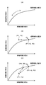
- FIG. 8 is an explanatory diagram showing ideal braking force distribution characteristics of the front and rear wheels.
- the vertical axis indicates the braking force distribution for the rear wheels
- the horizontal axis indicates the braking force distribution for the front wheels.
- the ideal braking force distribution is obtained by connecting points of ideal braking force distribution for each friction coefficient.
- the electric brake device 10 has a braking force applied to the front and rear wheels in accordance with an ideal braking force distribution characteristic as shown in FIG. 8A, that is, a braking force generated by the left and right front wheel brake mechanisms 20 and 22 and The braking force generated by the mechanisms 24 and 26 is distributed.
- the braking force of the front wheel brake mechanisms 20, 22 decreases as shown in FIG. 8B. That is, the braking force that was P1 ⁇ 2 becomes P1 ⁇ 1. If this is the case, the braking force of the rear wheel brake mechanisms 24, 26 is greater than the ideal braking force distribution value, and therefore rear locking occurs. In order to prevent such a rear lock, as shown in FIG. 8C, the rear wheel control unit 32 immediately applies the braking force of the left and right rear wheel brake mechanisms 24, 26 immediately after the failure of the first front wheel control unit 28. Is greatly reduced. 8 and 4, the braking force is reduced to P5 that is lower than the ideal braking force distribution value.
- the rear wheel control unit 32 determines the ideal braking force distribution characteristics of the rear wheel brake mechanisms 24 and 26. Is raised to P6 which is a value along Also, when the braking force of the front wheel brake mechanisms 20 and 22 is lower than that immediately after the failure of the first front wheel control unit 28, such as when the brake operation is loosened, the rear wheel control unit 32 is The value is in line with the ideal braking force distribution characteristics of the rear wheel brake mechanisms 24 and 26.
- one of the other non-failed control units increases the braking force of the brake mechanism to be controlled and does not break down.
- the other one of the other control units temporarily reduces the braking force of the brake mechanism to be controlled, and then controls in conjunction with the increase of the braking force by one of the other control units that do not malfunction. Increase the braking force of the target brake mechanism.
- the control unit for reducing the braking force temporarily sets the braking force of the brake mechanism to be controlled to a value lower than the ideal braking force distribution value in the full length direction (front-rear direction) of the vehicle.
- the rear wheel control unit 32 sets the left rear wheel brake.
- the braking force of the mechanism 24 and the right rear wheel brake mechanism 26 is temporarily reduced.
- the rear wheel control unit 32 sets the braking force of the left rear wheel brake mechanism 24 and the right rear wheel brake mechanism 26 to a value lower than the ideal braking force distribution value of the front and rear wheels in the vehicle.
- the first front wheel control unit 28 or the second front wheel control unit 30 when one of the first front wheel control unit 28 or the second front wheel control unit 30 fails, the first front wheel control unit 28 or the second front wheel control unit 30 The other increases the braking force of the left front wheel brake mechanism 20 and the right front wheel brake mechanism 22, and the rear wheel control unit 32 increases the braking force of the left rear wheel brake mechanism 24 and the right rear wheel brake mechanism 26. After the temporary reduction, the left rear wheel brake mechanism 24 and the right rear wheel are interlocked with the increase in the braking force of the left front wheel brake mechanism 20 and the right front wheel brake mechanism 22 by the other control unit that has not failed. The braking force of the brake mechanism 26 is increased. In the case where the second front wheel control unit 30 fails, the first front wheel control unit 28 and the second front wheel control unit 30 in the above description may be replaced with each other.
- the first front wheel control unit 28 and the second front wheel control unit 30 both have a predetermined braking force P1.
- the left and right front wheel brake mechanisms 20 and 22 are driven so as to be generated. That is, the left and right front wheel brake mechanisms 20 and 22 collectively generate a braking force of P1 ⁇ 2.
- the rear wheel control unit 32 (ECU 3) drives the left and right rear wheel brake mechanisms 24 and 26 so as to generate a predetermined braking force P2 ( ⁇ P1).
- the total braking force by the three controllers 28, 30, and 32 is P3.
- the rear wheel control unit 32 (ECU 3) fails at time T1, the power supply from the rear wheel control unit 32 to the left and right rear wheel brake mechanisms 24, 26 is lost, and the left and right rear wheel brake mechanisms 24, 26 are lost.
- the first front wheel control unit 28 and the second front wheel control unit 30 increase the power supplied to the left front wheel brake mechanism 20 and the right front wheel brake mechanism 22, respectively, and P3 (> P1) x 2 braking force is generated.
- the parking control unit 38 operates the parking brake mechanisms 34 and 36 to generate a braking force for braking the rear wheels 16 and 18.
- the braking force of the parking brake mechanisms 34 and 36 is lower than that of the left rear wheel brake mechanism 24 and the right rear wheel brake mechanism 26 that are service brakes, but gives a constant braking force to the rear wheels 16 and 18. And higher braking force can be obtained.
- the first front wheel control unit 28 and the second front wheel control unit 30 use the braking force of the left front wheel brake mechanism 20 and the right front wheel brake mechanism 22. Increase each.
- the parking control unit 38 operates the parking brake mechanisms 34 and 36 to generate a braking force for the left rear wheel 16 and the right rear wheel 18.
- the front wheel brake mechanism is set so as to output a stronger braking force than the rear wheel brake mechanism. For this reason, braking may be performed only with the left front wheel brake mechanism 20 and the right front wheel brake mechanism 22 without operating the parking brake mechanisms 34 and 36, but the parking brake mechanisms 34 and 36 are operated to move the vehicle forward and backward.
- the parking brake mechanisms 34 and 36 are operated to move the vehicle forward and backward.
- FIG. 6A a case where one of the front wheel control units (the first front wheel control unit 28 or the second front wheel control unit 30) and the rear wheel control unit 32 are sequentially failed will be described.
- FIG. 6B the case where the first front wheel control unit 28 (ECU1) fails first and then the rear wheel control unit 32 (ECU3) fails will be described as an example.
- the first front wheel control unit 28 and the second front wheel control unit 30 both have a predetermined braking force P1.
- the left and right front wheel brake mechanisms 20 and 22 are driven so as to be generated.
- the left and right front wheel brake mechanisms 20 and 22 collectively generate a braking force of P1 ⁇ 2.
- the rear wheel control unit 32 (ECU 3) drives the left and right rear wheel brake mechanisms 24 and 26 so as to generate a predetermined braking force P2 ( ⁇ P1).
- P2 predetermined braking force
- the total braking force by the three controllers 28, 30, and 32 is P3. If the first front wheel control unit 28 (ECU1) breaks down at time T1, the power supply from the first front wheel control unit 28 to the left and right front wheel brake mechanisms 20, 22 is lost, and the second front wheel control unit Only power from 30 is supplied. Therefore, the total braking force of the left and right front wheel brake mechanisms 20, 22 is halved to P1 ⁇ 1. In this case, the second front wheel control unit 30 (ECU 2) increases the amount of power supplied to the left and right front wheel brake mechanisms 20, 22, so that the left and right front wheel brake mechanisms 20, 22 are more than P1 ⁇ 1. A large braking force P4 is generated.
- the rear wheel control unit 32 reduces the amount of power supplied to the left and right rear wheel brake mechanisms 24 and 26 immediately after the failure of the first front wheel control unit 28, thereby The braking force is temporarily reduced to the braking force P5 ( ⁇ P2) of the brake mechanisms 24 and 26. This is to prevent the left and right rear wheels 16 and 18 from being locked (rear lock) due to a decrease in the braking force of the front wheel brake mechanisms 20 and 22 as described above. Thereafter, the rear wheel control unit 32 follows the increase in the braking force of the left and right front wheel brake mechanisms 20 and 22 and follows the ideal braking force distribution characteristics of the left and right rear wheel brake mechanisms 24 and 26. Increase braking force to P6.
- the rear wheel control unit 32 (ECU 3) breaks down at time T2
- power is not supplied from the rear wheel control unit 32 to the left and right rear wheel brake mechanisms 24, 26, and the left and right rear wheel brake mechanisms 24 are stopped.
- 26 is zero.
- the second front wheel control unit 30 further increases the power supplied to the left front wheel brake mechanism 20 and the right front wheel brake mechanism 22, so that the left and right front wheel brake mechanisms 20, 22 are larger than P4.
- a braking force P7 is generated.
- the parking control unit 38 operates the parking brake mechanisms 34 and 36 to generate a braking force for braking the rear wheels 16 and 18.
- the braking force of the parking brake mechanisms 34 and 36 is lower than that of the left rear wheel brake mechanism 24 and the right rear wheel brake mechanism 26 that are service brakes, but gives a constant braking force to the rear wheels 16 and 18. Can do.
- the first front wheel control unit 28 or the second front wheel control unit 30 and the rear wheel control unit 32 fail, the first front wheel control unit 28 or the second front wheel control unit 28
- the other of the front wheel control units 30 increases the braking force of the left front wheel brake mechanism 20 and the right front wheel brake mechanism 22, and the parking control unit 38 operates the parking brake mechanisms 34 and 36 to operate the left rear wheel 16. And the braking force with respect to the right rear wheel 18 is generated.
- the rear wheel control unit 32 fails first, and then one of the front wheel control units (the first front wheel control unit 28 or the second front wheel control unit 30) fails.
- the first front wheel control unit 28 and the second front wheel control unit 30 are connected to the left front wheel brake mechanism 20 and the right front wheel, respectively.
- the braking force of the brake mechanism 22 is increased.
- the parking control unit 38 operates the parking brake mechanisms 34 and 36 to brake the rear wheels 16 and 18.
- the front wheel control unit on the non-failed side causes the left and right front wheel brake mechanisms 20 and 22 to generate a larger braking force. . That is, even if the order of failure is different, the final state is the same as in FIG.
- FIG. 7A a case will be described in which both of the front wheel control units (the first front wheel control unit 28 and the second front wheel control unit 30) sequentially fail.
- FIG. 7B the case where the first front wheel control unit 28 fails first and then the second front wheel control unit 30 fails will be described as an example.
- the first front wheel control unit 28 and the second front wheel control unit 30 both have a predetermined braking force P1.
- the left and right front wheel brake mechanisms 20 and 22 are driven so as to be generated. That is, the left and right front wheel brake mechanisms 20 and 22 collectively generate a braking force of P1 ⁇ 2.
- the rear wheel control unit 32 (ECU 3) drives the left and right rear wheel brake mechanisms 24 and 26 so as to generate a predetermined braking force P2 ( ⁇ P1).
- the total braking force by the three controllers 28, 30, and 32 is P3.
- the first front wheel control unit 28 (ECU1) breaks down at time T1
- the power supply from the first front wheel control unit 28 to the left and right front wheel brake mechanisms 20, 22 is lost, and the second front wheel control unit Only power from 30 is supplied. Therefore, the total braking force of the left and right front wheel brake mechanisms 20, 22 is halved to P1 ⁇ 1.
- the second front wheel control unit 30 (ECU 2) increases the amount of power supplied to the left and right front wheel brake mechanisms 20, 22, so that the left and right front wheel brake mechanisms 20, 22 are more than P1 ⁇ 1. A large braking force P4 is generated.
- the rear wheel control unit 32 (ECU 3) temporarily reduces the amount of power supplied to the left and right rear wheel brake mechanisms 24, 26 immediately after the failure of the first front wheel control unit 28, and The braking force is reduced to the braking force P5 ( ⁇ P2) of the rear wheel brake mechanisms 24, 26. This is to prevent the left and right rear wheels 16 and 18 from being locked (rear lock) due to a decrease in the braking force of the front wheel brake mechanisms 20 and 22 as described above. Thereafter, the rear wheel control unit 32 follows the increase in the braking force of the left and right front wheel brake mechanisms 20 and 22 and follows the ideal braking force distribution characteristics of the left and right rear wheel brake mechanisms 24 and 26. Increase braking force to P6.
- the rear wheel control unit 32 (ECU 3) reduces the amount of power supplied to the left and right rear wheel brake mechanisms 24 and 26 immediately after the failure of the second front wheel control unit 30, thereby The braking force is reduced to the braking force P7 ( ⁇ P6) of the mechanisms 24 and 26. This is to prevent the rear lock caused by the braking force of the front wheel brake mechanisms 20, 22 suddenly becoming zero. Thereafter, the rear wheel control unit 32 gradually increases the power supplied to the left and right rear wheel brake mechanisms 24 and 26 to brake the vehicle with a braking force (P8 in FIG. 7) that does not cause a rear lock.
- the control unit 30 may be replaced with the left front wheel brake mechanism 20 and the right front wheel brake mechanism 22, respectively.
- Another form of failure is when the rear wheel control unit 32 and the parking control unit 38 fail.
- the first front wheel control unit 28 and the second front wheel control unit are used.
- the braking force of the left and right front wheel brake mechanisms 20, 22 may be increased by the control unit 30.
- the electric brake device 10 when at least one of the three control units 28, 30, and 32 fails, at least one of the non-failed control units gives the braking force. Since it is temporarily reduced, it is advantageous in maintaining the braking force distribution between the wheel pairs in an appropriate state when the braking force of the brake mechanism to be controlled by the malfunctioning control unit suddenly decreases.
- the electric brake device 10 can control the four brake mechanisms 20, 22, 24, and 26 with the three control units 28, 30, and 32, the number of parts of the electric brake device 10 is reduced and the vehicle cost is reduced. This is advantageous.
- the electric brake device 10 increases the braking force of one of the other control units that do not fail, and the other control unit that does not fail.
- the electric brake device 10 controls the first brake mechanism and the second brake mechanism with the two control units, it is advantageous in increasing the availability of the first brake mechanism and the second brake mechanism.
- the electric brake device 10 assigns two control units 28 and 30 to the left and right front wheel brake mechanisms 20 and 22, and assigns one control unit 32 on the left and right sides to the rear wheel brake mechanisms 24 and 26. Therefore, even if one control unit fails, the remaining front wheel brake mechanisms 20 and 22 can be controlled, which is advantageous in increasing the redundancy of the front wheel brake, which is more important during braking.
- the electric brake device 10 reduces the braking force based on the ideal braking force distribution value set in the vehicle, the controller that is not malfunctioning is advantageous in stabilizing the vehicle posture during braking. .
- the electric brake device 10 temporarily reduces the braking force of the rear wheel brake mechanisms 24 and 26 when at least one of the first front wheel control unit 28 or the second front wheel control unit 30 fails. Therefore, when the braking force of the front-wheel brake mechanisms 20 and 22 suddenly decreases due to a failure of the front-wheel control unit, rear-locking is prevented from occurring due to the braking force distribution of the front and rear wheels deviating from the ideal braking force distribution. This is advantageous.
- the electric brake device 10 temporarily reduces the braking force of the rear wheel brake mechanisms 24 and 26 when one of the front wheel control units 28 and 30 breaks down, and then uses the other of the front wheel control units 28 and 30. Since the braking force of the rear wheel brake mechanisms 24, 26 is increased in conjunction with the increase of the braking force of the front wheel brake mechanisms 20, 22, it is advantageous in securing the braking force of the entire vehicle while preventing the rear lock. . Further, when the rear wheel control unit 32 breaks down, the electric brake device 10 increases the braking force of the left front wheel brake mechanism 20 and the right front wheel brake mechanism 22, respectively. This is advantageous in ensuring a braking force close to that before the failure.
- the electric brake device 10 operates the parking brake mechanisms 34 and 36 to generate braking force for the left rear wheel 16 and the right rear wheel 18 when the rear wheel control unit 32 breaks down. It is possible to prevent the power distribution from changing extremely and obtain a higher braking force. In addition, when one of the front wheel control units 28 and 30 and the rear wheel control unit 32 break down, the electric brake device 10 applies the braking force of the front wheel brake mechanisms 20 and 22 by the front wheel control units 28 and 30.
- each brake mechanism 20, 22, 24, 26 obtains a braking force by pressing the friction member with the electric actuator against the friction target member that rotates together with the wheel. This is advantageous in improving the responsiveness to the brake operation as compared with the type brake, and is advantageous in performing various brake controls according to the vehicle state.
- the electric brake device 10 uses a brake disc as a friction member and a brake pad as a friction member and employs a disc brake system with high heat dissipation, which is advantageous in improving the durability of the brake mechanism. .
- the left rear wheel brake mechanism 24 and the right rear wheel brake mechanism 26 serve also as the parking brake mechanisms 34 and 36, the vehicle is compared with the case where a dedicated parking brake mechanism is provided. This is advantageous in reducing the weight of the vehicle and simplifying the vehicle configuration.
- the left rear wheel brake mechanism 24 and the right rear wheel brake mechanism 26 are This is advantageous in reducing the load on each brake mechanism as compared with the case where the parking brake mechanisms 34 and 36 are also used. Further, since the electric brake device 10 is provided with two batteries for supplying electric power to the brake mechanisms 20, 22, 24, 26, the brake mechanism 20, 22, 24 is operated by the sub battery 42 even when the main battery 40 fails. , 26 can be operated, which is advantageous in increasing the redundancy of the brake mechanisms 20, 22, 24, 26.
- the four wheels of the vehicle are spaced apart in the full width direction from the first wheel pair consisting of the first wheel and the second wheel that are spaced apart in the full width direction of the vehicle.
- the first wheel pair and the second wheel pair that are spaced from the first wheel pair in the full length direction of the vehicle.
- the wheel is the left front wheel 12
- the second wheel is the right front wheel 14
- the third wheel is the left rear wheel 16
- the fourth wheel is the right rear wheel 18
- the present invention is not limited to this.
- the first wheel may be the left rear wheel 16
- the second wheel may be the right rear wheel 18
- the third wheel may be the left front wheel 12
- the fourth wheel may be the right front wheel 14.
- the brake mechanisms 24 and 26 of the left and right rear wheels 16 and 18 are controlled by two control units (first control unit and second control unit), and the brake mechanisms 20 and 22 of the left and right front wheels 12 and 14 are controlled. Are controlled by a single control unit (third control unit).
- the brake mechanisms 20, 22, 24, and 26 of the four wheels 12, 14, 16, and 18 are controlled by the three control units 28, 30, and 32 .
- four or more control units may be provided.
- the rear wheel control unit (first rear wheel control unit) 32 as a control unit for controlling the left and right rear wheel brake mechanisms 24, 26, a second rear wheel control is performed.
- a portion 33 is provided.
- the first front wheel control unit 28 fails, the braking force of the second front wheel control unit 30 is increased.
- the first and second rear wheel controls 32 and 33 temporarily reduce the braking force so as not to lock the rear, and then increase the braking force along the ideal braking force distribution.
- the case where the second front wheel control unit 30 fails is the same as the case where the first front wheel control unit 28 fails.
- the braking force of the second rear wheel control unit 33 is increased.
- the first and second front wheel controllers 28 and 30 also increase the braking force.
- the case where the second rear wheel control unit 33 fails is the same as the case where the first rear wheel control unit 32 fails.
- the first and second rear wheel control units 32 and 33 perform braking to such an extent that the rear lock does not occur.
- the braking force of the second front wheel control unit 30 and the second rear wheel control unit 33 is increased.
- the first front wheel control unit 28 and the second rear wheel control unit 33 fail, or when the second front wheel control unit 30 and the first rear wheel control unit 32 fail, the second The case where the front wheel control unit 30 and the second rear wheel control unit 33 fail is the same as the case where the first front wheel control unit 28 and the first rear wheel control unit 32 fail.
- the braking force of the first and second front wheel control units 28 and 30 is increased. As a result, stable braking can be performed even when the control unit has a double failure.
Landscapes
- Engineering & Computer Science (AREA)
- Mechanical Engineering (AREA)
- Transportation (AREA)
- General Engineering & Computer Science (AREA)
- Regulating Braking Force (AREA)
- Valves And Accessory Devices For Braking Systems (AREA)
- Braking Systems And Boosters (AREA)
Abstract
L'invention concerne un dispositif de frein électromécanique (10) équipé d'au moins trois unités de commande: une première unité de commande de roues avant (28) permettant de commander un mécanisme de frein de roue avant-gauche (20) et un mécanisme de frein de roue avant-droite (22); une seconde unité de commande de roues avant (30) permettant de commander de manière similaire le mécanisme de frein de roue avant-gauche (20) et le mécanisme de frein de roue avant-droite (22); et une unité de commande de roues arrière (32) permettant de commander un mécanisme de frein de roue arrière-gauche (24) et un mécanisme de frein de roue arrière-droite (26). Lorsqu'au moins l'une des trois unités de commande (28), (30), (32) présente une défaillance, au moins l'une des autres unités de commande qui ne présente pas de défaillance réduit temporairement la force de freinage du mécanisme de frein commandé par cette dernière.
Priority Applications (2)
| Application Number | Priority Date | Filing Date | Title |
|---|---|---|---|
| US15/515,454 US10407033B2 (en) | 2015-07-02 | 2016-05-10 | Electric brake device |
| EP16817562.8A EP3318459B1 (fr) | 2015-07-02 | 2016-05-10 | Dispositif de frein électromécanique |
Applications Claiming Priority (2)
| Application Number | Priority Date | Filing Date | Title |
|---|---|---|---|
| JP2015133304A JP6589416B2 (ja) | 2015-07-02 | 2015-07-02 | 電動ブレーキ装置 |
| JP2015-133304 | 2015-07-02 |
Publications (1)
| Publication Number | Publication Date |
|---|---|
| WO2017002453A1 true WO2017002453A1 (fr) | 2017-01-05 |
Family
ID=57608574
Family Applications (1)
| Application Number | Title | Priority Date | Filing Date |
|---|---|---|---|
| PCT/JP2016/063811 Ceased WO2017002453A1 (fr) | 2015-07-02 | 2016-05-10 | Dispositif de frein électromécanique |
Country Status (4)
| Country | Link |
|---|---|
| US (1) | US10407033B2 (fr) |
| EP (1) | EP3318459B1 (fr) |
| JP (1) | JP6589416B2 (fr) |
| WO (1) | WO2017002453A1 (fr) |
Families Citing this family (19)
| Publication number | Priority date | Publication date | Assignee | Title |
|---|---|---|---|---|
| KR102556617B1 (ko) * | 2016-09-05 | 2023-07-19 | 에이치엘만도 주식회사 | 전자제어식 브레이크 시스템 및 그 제어방법 |
| IT201700105896A1 (it) | 2017-09-21 | 2019-03-21 | Freni Brembo Spa | Impianto frenante per veicoli di tipo brake by wire munito di azionamento elettrico e di back-up elettrico |
| JP7172352B2 (ja) * | 2018-09-24 | 2022-11-16 | 株式会社アドヴィックス | 制動制御装置 |
| DE102019207517A1 (de) | 2019-05-22 | 2020-11-26 | Volkswagen Aktiengesellschaft | Bremssteuersystem |
| CN114761291B (zh) * | 2019-12-10 | 2024-06-14 | 沃尔沃卡车集团 | 冗余制动设备系统的控制 |
| JP7418575B2 (ja) | 2019-12-10 | 2024-01-19 | ボルボトラックコーポレーション | 冗長制動システム |
| EP3835148B1 (fr) | 2019-12-13 | 2022-09-21 | KNORR-BREMSE Systeme für Nutzfahrzeuge GmbH | Système et procédé d'arrêt automatique d'un véhicule autonome |
| US12296469B2 (en) * | 2020-07-10 | 2025-05-13 | Lg Electronics Inc. | Device of brake controlling and robot including thereof |
| KR102880988B1 (ko) * | 2020-10-22 | 2025-11-04 | 현대모비스 주식회사 | 전동식 브레이크 장치 및 제어방법 |
| JP6936380B1 (ja) | 2020-12-28 | 2021-09-15 | 本田技研工業株式会社 | 車両制御システム、および車両制御方法 |
| KR20220102001A (ko) | 2021-01-12 | 2022-07-19 | 현대모비스 주식회사 | 전동식 브레이크의 제어장치 및 방법 |
| JP7718141B2 (ja) * | 2021-07-29 | 2025-08-05 | 株式会社アドヴィックス | 車両の制動制御装置 |
| EP4209399A1 (fr) * | 2022-01-05 | 2023-07-12 | Volvo Car Corporation | Système de commande de frein pour commander un système de frein, véhicule et procédé de fonctionnement d'un système de commande de frein |
| US20240075817A1 (en) * | 2022-09-07 | 2024-03-07 | Harbinger Motors Inc. | Commercial electric vehicle braking systems |
| JP2025533036A (ja) * | 2022-09-30 | 2025-10-03 | 深▲ジェン▼引望智能技術有限公司 | 制動システム、液圧装置、および制御方法 |
| WO2024065830A1 (fr) * | 2022-09-30 | 2024-04-04 | 华为技术有限公司 | Système de freinage et procédé et dispositif de commande |
| KR20250015516A (ko) * | 2023-07-25 | 2025-02-03 | 에이치엘만도 주식회사 | 전자식 주차 브레이크 제어 시스템 및 이를 제어하는 방법 |
| US12459478B2 (en) | 2023-10-18 | 2025-11-04 | Ford Global Technologies, Llc | Brake architecture for a full, four corner electromechanical braking system |
| FR3157316B1 (fr) * | 2023-12-22 | 2026-02-13 | Hitachi Astemo France | Système de freinage pour véhicule automobile |
Citations (2)
| Publication number | Priority date | Publication date | Assignee | Title |
|---|---|---|---|---|
| JP2000016258A (ja) * | 1998-06-26 | 2000-01-18 | Toyota Motor Corp | 車両用電動ブレーキ装置 |
| WO2012121199A1 (fr) * | 2011-03-07 | 2012-09-13 | Ntn株式会社 | Véhicule électrique |
Family Cites Families (4)
| Publication number | Priority date | Publication date | Assignee | Title |
|---|---|---|---|---|
| JP2000225935A (ja) * | 1999-02-03 | 2000-08-15 | Toyota Motor Corp | 電気制御ブレーキシステム |
| JP4723706B2 (ja) * | 1999-09-02 | 2011-07-13 | トヨタ自動車株式会社 | 車両用電気制御システム |
| DE102006059919A1 (de) * | 2006-12-19 | 2008-07-03 | Robert Bosch Gmbh | Datenverarbeitungssystem für ein Kraftfahreug |
| KR101228492B1 (ko) * | 2010-06-28 | 2013-01-31 | 현대모비스 주식회사 | 차량의 제동 제어시스템 및 제동 제어방법 |
-
2015
- 2015-07-02 JP JP2015133304A patent/JP6589416B2/ja active Active
-
2016
- 2016-05-10 EP EP16817562.8A patent/EP3318459B1/fr active Active
- 2016-05-10 WO PCT/JP2016/063811 patent/WO2017002453A1/fr not_active Ceased
- 2016-05-10 US US15/515,454 patent/US10407033B2/en active Active
Patent Citations (2)
| Publication number | Priority date | Publication date | Assignee | Title |
|---|---|---|---|---|
| JP2000016258A (ja) * | 1998-06-26 | 2000-01-18 | Toyota Motor Corp | 車両用電動ブレーキ装置 |
| WO2012121199A1 (fr) * | 2011-03-07 | 2012-09-13 | Ntn株式会社 | Véhicule électrique |
Also Published As
| Publication number | Publication date |
|---|---|
| JP2017013669A (ja) | 2017-01-19 |
| EP3318459B1 (fr) | 2021-04-14 |
| US10407033B2 (en) | 2019-09-10 |
| EP3318459A1 (fr) | 2018-05-09 |
| US20170210361A1 (en) | 2017-07-27 |
| JP6589416B2 (ja) | 2019-10-16 |
| EP3318459A4 (fr) | 2019-05-01 |
Similar Documents
| Publication | Publication Date | Title |
|---|---|---|
| JP6589416B2 (ja) | 電動ブレーキ装置 | |
| JP6565388B2 (ja) | 電動ブレーキ装置 | |
| JP6575175B2 (ja) | 電動ブレーキ装置 | |
| JP7293345B2 (ja) | 電気自動車を制御するためのシステムおよび方法 | |
| CN112739593B (zh) | 汽车的驻车制动系统、汽车及其控制方法 | |
| KR101228492B1 (ko) | 차량의 제동 제어시스템 및 제동 제어방법 | |
| JP2000225935A5 (fr) | ||
| JP7230009B2 (ja) | 電気作動および電気的バックアップを設けられた車両用ブレーキ・バイ・ワイヤ制動システム | |
| CN103802674B (zh) | 用于在紧急运行中操控车辆的执行器的方法和控制单元 | |
| US20110155521A1 (en) | Asymmetrical electric braking architecture for aircraft | |
| WO2016178428A1 (fr) | Système de frein électrique | |
| JP7239709B2 (ja) | 車両の電動制動および電動操舵のための制御アーキテクチャおよび当該制御アーキテクチャの制御方法 | |
| JP7837744B2 (ja) | 制動装置、予備ブレーキ制御装置 | |
| CN118514660A (zh) | 用于车辆的制动系统和用于制动车辆的方法 | |
| JP7793112B2 (ja) | ブレーキ制御装置、機械ブレーキ装置、およびブレーキ制御システム | |
| KR20250031487A (ko) | 차량제동 제어방법 및 장치 | |
| KR20250143120A (ko) | 철도 차량에서 적어도 부분적으로 전기적으로 작동되는 마찰 브레이크 컨트롤러를 작동하기 위한 조합된 에너지 저장 장치 유형을 포함하는 에너지 공급 시스템을 구비한 브레이크 시스템 | |
| CN118722549A (zh) | Emb驻车系统的主副控制器冗余架构及冗余控制方法 |
Legal Events
| Date | Code | Title | Description |
|---|---|---|---|
| 121 | Ep: the epo has been informed by wipo that ep was designated in this application |
Ref document number: 16817562 Country of ref document: EP Kind code of ref document: A1 |
|
| REEP | Request for entry into the european phase |
Ref document number: 2016817562 Country of ref document: EP |
|
| WWE | Wipo information: entry into national phase |
Ref document number: 15515454 Country of ref document: US Ref document number: 2016817562 Country of ref document: EP |
|
| NENP | Non-entry into the national phase |
Ref country code: DE |