WO2017002559A1 - Pile à combustible - Google Patents
Pile à combustible Download PDFInfo
- Publication number
- WO2017002559A1 WO2017002559A1 PCT/JP2016/067043 JP2016067043W WO2017002559A1 WO 2017002559 A1 WO2017002559 A1 WO 2017002559A1 JP 2016067043 W JP2016067043 W JP 2016067043W WO 2017002559 A1 WO2017002559 A1 WO 2017002559A1
- Authority
- WO
- WIPO (PCT)
- Prior art keywords
- air electrode
- phase
- electrode
- fuel cell
- layer
- Prior art date
- Legal status (The legal status is an assumption and is not a legal conclusion. Google has not performed a legal analysis and makes no representation as to the accuracy of the status listed.)
- Ceased
Links
Images

Classifications
-
- H—ELECTRICITY
- H01—ELECTRIC ELEMENTS
- H01M—PROCESSES OR MEANS, e.g. BATTERIES, FOR THE DIRECT CONVERSION OF CHEMICAL ENERGY INTO ELECTRICAL ENERGY
- H01M4/00—Electrodes
- H01M4/86—Inert electrodes with catalytic activity, e.g. for fuel cells
- H01M4/90—Selection of catalytic material
- H01M4/9016—Oxides, hydroxides or oxygenated metallic salts
- H01M4/9025—Oxides specially used in fuel cell operating at high temperature, e.g. SOFC
- H01M4/9033—Complex oxides, optionally doped, of the type M1MeO3, M1 being an alkaline earth metal or a rare earth, Me being a metal, e.g. perovskites
-
- H—ELECTRICITY
- H01—ELECTRIC ELEMENTS
- H01M—PROCESSES OR MEANS, e.g. BATTERIES, FOR THE DIRECT CONVERSION OF CHEMICAL ENERGY INTO ELECTRICAL ENERGY
- H01M4/00—Electrodes
- H01M4/86—Inert electrodes with catalytic activity, e.g. for fuel cells
- H01M4/8605—Porous electrodes
-
- H—ELECTRICITY
- H01—ELECTRIC ELEMENTS
- H01M—PROCESSES OR MEANS, e.g. BATTERIES, FOR THE DIRECT CONVERSION OF CHEMICAL ENERGY INTO ELECTRICAL ENERGY
- H01M4/00—Electrodes
- H01M4/86—Inert electrodes with catalytic activity, e.g. for fuel cells
- H01M4/8647—Inert electrodes with catalytic activity, e.g. for fuel cells consisting of more than one material, e.g. consisting of composites
- H01M4/8657—Inert electrodes with catalytic activity, e.g. for fuel cells consisting of more than one material, e.g. consisting of composites layered
-
- H—ELECTRICITY
- H01—ELECTRIC ELEMENTS
- H01M—PROCESSES OR MEANS, e.g. BATTERIES, FOR THE DIRECT CONVERSION OF CHEMICAL ENERGY INTO ELECTRICAL ENERGY
- H01M8/00—Fuel cells; Manufacture thereof
- H01M8/10—Fuel cells with solid electrolytes
- H01M8/12—Fuel cells with solid electrolytes operating at high temperature, e.g. with stabilised ZrO2 electrolyte
- H01M8/124—Fuel cells with solid electrolytes operating at high temperature, e.g. with stabilised ZrO2 electrolyte characterised by the process of manufacturing or by the material of the electrolyte
- H01M8/1246—Fuel cells with solid electrolytes operating at high temperature, e.g. with stabilised ZrO2 electrolyte characterised by the process of manufacturing or by the material of the electrolyte the electrolyte consisting of oxides
- H01M8/1253—Fuel cells with solid electrolytes operating at high temperature, e.g. with stabilised ZrO2 electrolyte characterised by the process of manufacturing or by the material of the electrolyte the electrolyte consisting of oxides the electrolyte containing zirconium oxide
-
- H—ELECTRICITY
- H01—ELECTRIC ELEMENTS
- H01M—PROCESSES OR MEANS, e.g. BATTERIES, FOR THE DIRECT CONVERSION OF CHEMICAL ENERGY INTO ELECTRICAL ENERGY
- H01M4/00—Electrodes
- H01M4/86—Inert electrodes with catalytic activity, e.g. for fuel cells
- H01M2004/8678—Inert electrodes with catalytic activity, e.g. for fuel cells characterised by the polarity
- H01M2004/8689—Positive electrodes
-
- H—ELECTRICITY
- H01—ELECTRIC ELEMENTS
- H01M—PROCESSES OR MEANS, e.g. BATTERIES, FOR THE DIRECT CONVERSION OF CHEMICAL ENERGY INTO ELECTRICAL ENERGY
- H01M8/00—Fuel cells; Manufacture thereof
- H01M8/10—Fuel cells with solid electrolytes
- H01M8/12—Fuel cells with solid electrolytes operating at high temperature, e.g. with stabilised ZrO2 electrolyte
- H01M2008/1293—Fuel cells with solid oxide electrolytes
-
- Y—GENERAL TAGGING OF NEW TECHNOLOGICAL DEVELOPMENTS; GENERAL TAGGING OF CROSS-SECTIONAL TECHNOLOGIES SPANNING OVER SEVERAL SECTIONS OF THE IPC; TECHNICAL SUBJECTS COVERED BY FORMER USPC CROSS-REFERENCE ART COLLECTIONS [XRACs] AND DIGESTS
- Y02—TECHNOLOGIES OR APPLICATIONS FOR MITIGATION OR ADAPTATION AGAINST CLIMATE CHANGE
- Y02E—REDUCTION OF GREENHOUSE GAS [GHG] EMISSIONS, RELATED TO ENERGY GENERATION, TRANSMISSION OR DISTRIBUTION
- Y02E60/00—Enabling technologies; Technologies with a potential or indirect contribution to GHG emissions mitigation
- Y02E60/30—Hydrogen technology
- Y02E60/50—Fuel cells
Definitions
- the present invention relates to a fuel cell.
- a fuel cell including a fuel electrode, an air electrode, and a solid electrolyte layer disposed between the fuel electrode and the air electrode is known.
- a material for the air electrode a perovskite oxide represented by the general formula ABO 3 and containing at least one of La and Sr at the A site is suitable (see, for example, Patent Document 1).
- the output of the fuel cell may decrease as power generation is repeated.
- the present inventors have newly found that one of the causes of the decrease in output is the deterioration of the air electrode, and this deterioration of the air electrode is related to the proportion of strontium oxide present inside.
- the present invention is based on such new knowledge and aims to provide a fuel cell capable of suppressing a decrease in output.
- the fuel cell according to the present invention includes a fuel electrode, an air electrode, and a solid electrolyte layer disposed between the fuel electrode and the air electrode.
- the air electrode is represented by a general formula ABO 3 and includes a main phase composed of a perovskite oxide containing at least one of La and Sr at the A site, and a second phase composed of strontium oxide.
- the area occupation ratio of the second phase in the cross section of the air electrode is 0.05% or more and 3% or less.
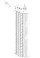
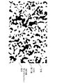
- Sectional view showing the configuration of the fuel cell Backscattered electron image of air electrode cross section The figure which shows the image analysis result of FIG.
- the fuel cell 10 is a so-called solid oxide fuel cell (SOFC).
- SOFC solid oxide fuel cell
- the fuel cell 10 may take the form of a vertical stripe type, a horizontal stripe type, a fuel electrode support type, an electrolyte flat plate type, or a cylindrical type.
- FIG. 1 is a cross-sectional view showing the configuration of the fuel cell 10.
- the fuel cell 10 includes a fuel electrode 20, a solid electrolyte layer 30, a barrier layer 40, an air electrode 50, and a current collecting layer 60.
- the fuel electrode 20 functions as an anode of the fuel cell 10. As illustrated in FIG. 1, the fuel electrode 20 includes a fuel electrode current collecting layer 21 and a fuel electrode active layer 22.
- the anode current collecting layer 21 is a porous body excellent in gas permeability.
- materials conventionally used for SOFC anode current collecting layers can be used.
- NiO nickel oxide
- -8YSZ 8 mol% yttria is stabilized).
- Zirconia and NiO—Y 2 O 3 (yttria).
- NiO nickel oxide
- Y 2 O 3 yttria
- the thickness of the anode current collecting layer 21 can be set to 0.1 mm to 5.0 mm, for example.
- the anode active layer 22 is disposed on the anode current collecting layer 21.
- the anode active layer 22 is a denser porous body than the anode current collecting layer 21.
- materials conventionally used for the anode active layer of SOFC can be used, for example, NiO-8YSZ.
- NiO-8YSZ materials conventionally used for the anode active layer of SOFC
- the thickness of the anode active layer 22 can be set to, for example, 5.0 ⁇ m to 30 ⁇ m.
- the solid electrolyte layer 30 is disposed between the fuel electrode 20 and the air electrode 50. In the present embodiment, the solid electrolyte layer 30 is sandwiched between the fuel electrode 20 and the barrier layer 40. The solid electrolyte layer 30 has a function of transmitting oxygen ions generated at the air electrode 50. The solid electrolyte layer 30 is denser than the fuel electrode 20 and the air electrode 50.
- the solid electrolyte layer 30 may contain ZrO 2 (zirconia) as a main component.
- the solid electrolyte layer 30 may contain additives such as Y 2 O 3 (yttria) and / or Sc 2 O 3 (scandium oxide) in addition to zirconia. These additives function as stabilizers.
- the molar composition ratio of the stabilizer to zirconia can be about 3:97 to 20:80. Therefore, examples of the material of the solid electrolyte layer 30 include 3YSZ, 8YSZ, 10YSZ, or ScSZ (scandia-stabilized zirconia).
- the thickness of the solid electrolyte layer 30 can be set to 3 ⁇ m to 30 ⁇ m, for example.
- the composition X containing the substance Y as the main component means that the substance Y accounts for 70% by weight or more, more preferably 90% by weight or more in the entire composition X. To do.
- the barrier layer 40 is disposed between the solid electrolyte layer 30 and the air electrode 50.
- the barrier layer 40 suppresses the formation of a high resistance layer between the solid electrolyte layer 30 and the air electrode 50.
- the barrier layer 40 is denser than the fuel electrode 20 and the air electrode 50.
- the barrier layer 40 can contain a ceria-based material such as GDC (gadolinium doped ceria) or SDC (samarium doped ceria) as a main component.
- the thickness of the barrier layer 40 can be set to 3 ⁇ m to 20 ⁇ m, for example.
- the air electrode 50 is disposed on the barrier layer 40.
- the air electrode 50 functions as a cathode of the fuel cell 10.
- the air electrode 50 is a porous body.
- the air electrode 50 is represented by the general formula ABO 3 and contains a perovskite oxide containing at least one of La and Sr at the A site as a main component.
- a perovskite oxide (La, Sr) (Co, Fe) O 3 (lanthanum strontium cobalt ferrite), (La, Sr) FeO 3 (lanthanum strontium ferrite), (La, Sr) CoO 3 ( Examples thereof include, but are not limited to, lanthanum strontium cobaltite, La (Ni, Fe) O 3 (lanthanum nickel ferrite), and (La, Sr) MnO 3 (lanthanum strontium manganate).
- the air electrode 50 contains strontium oxide (SrO) as a subcomponent.
- SrO has a cubic sodium chloride crystal structure.
- the area occupation ratio of the main phase composed of the main component perovskite oxide is not particularly limited, but may be 91% or more and 99.95% or less.
- the area occupation ratio of the second phase composed of SrO is 0.05% or more and 3% or less.
- the sinterability of the air electrode 50 can be improved and the skeleton of the porous structure can be strengthened. It can suppress that a microstructure changes. As a result, the durability of the air electrode 50 can be improved.
- the “area occupation ratio of the substance Z in the cross section” refers to the ratio of the total area of the substance Z to the total area including the pores and the solid phase. A method for calculating the area occupancy will be described later.
- the average equivalent circle diameter of the second phase in the cross section of the air electrode 50 is preferably 10 nm or more and 500 nm or less. Thereby, the deterioration rate of the air electrode 50 can be further reduced.
- the equivalent circle diameter is a diameter of a circle having the same area as the second phase on an analysis image obtained by analyzing an FE-SEM (Field Emission-Scanning Electron Microscope) image described later.
- the average equivalent circle diameter is a value obtained by arithmetically averaging the equivalent circle diameters of 20 or more second phases. It is preferable that 20 or more second phases to be measured for the equivalent circle diameter are arbitrarily selected from 5 or more FE-SEM images.
- the air electrode 50 is constituted by a perovskite oxide that is represented by the general formula ABO 3 and is different from the main phase, and an oxide of a constituent element of the main phase.
- a third phase may be included.
- the constituent element oxide of the main phase include SrO, (Co, Fe) 3 O 4 , and Co 3 O 4 .
- (Co, Fe) 3 O 4 includes Co 2 FeO 4 , Co 1.5 Fe 1.5 O 4 , CoFe 2 O 4 , and the like.
- the area occupancy of the third phase in the cross section of the air electrode 50 is preferably 0.5% or more and 10% or less. Thereby, not only after firing but also microcracks after the thermal cycle test can be suppressed.
- the thermal cycle test means that the temperature is raised from room temperature to 800 ° C. in 2 hours while maintaining a reducing atmosphere by supplying Ar gas and hydrogen gas (4% with respect to Ar) to the fuel electrode, and then at room temperature in 4 hours. This is a test in which the cycle to lower the temperature is repeated 10 times.
- the current collecting layer 60 is disposed on the air electrode 50.
- the current collecting layer 60 can be formed of a perovskite complex oxide represented by the following composition formula (1), but is not limited thereto.
- the material of the current collecting layer 60 is preferably smaller in electrical resistance than the material of the air electrode 50.
- Substances other than La may be contained in the A site of the composition formula (1), and substances other than Ni, Fe and Cu may be contained in the B site.
- m and n are 0.95 or more and 1.05 or less
- x (Fe) is 0.03 or more and 0.3 or less
- y (Cu) is 0.05 or more and 0.5 or less.
- ⁇ is 0 or more and 0.8 or less.
- FIG. 2 is an example of a backscattered electron image showing a cross section of the air electrode 50 magnified by a magnification of 10,000 by FE-SEM using a backscattered electron detector.
- FIG. 2 shows a cross section of an air electrode 50 containing (La, Sr) (Co, Fe) O 3 as a main component.
- the cross section of the air electrode 50 is preliminarily subjected to precision mechanical polishing and ion milling processing.
- the backscattered electron image in FIG. 2 was obtained by an FE-SEM (model: ULTRA55, acceleration voltage: 1.5 kV, working distance: 2 mm) manufactured by Zeiss (Germany).
- the main phase ((La, Sr) (Co, Fe) O 3 ), the second phase (SrO), and the pores are different in brightness
- the main phase is “gray white”
- the second phase is “gray” "The pores are displayed in black.” From the contrast of the reflected electron image, the main phase, the second phase, and the pores can be identified.
- FIG. 3 is a diagram showing a result of image analysis of the reflected electron image shown in FIG. 2 using image analysis software HALCON manufactured by MVTec (Germany).
- the second phase is outlined and surrounded by a black solid line.
- Air electrode material As an air electrode material constituting the air electrode 50, a mixed material containing a perovskite oxide as a main component and SrO as a subcomponent can be used. SrO may be mixed in the form of strontium carbonate, strontium hydroxide or strontium nitrate.
- the area occupancy of the second phase in the air electrode 50 can be adjusted by adjusting the amount of material powder containing SrO.
- the average equivalent circle diameter of the second phase in the air electrode 50 can be adjusted by adjusting the particle size of the material powder containing SrO.
- precise classification including adjustment of the upper limit value and the lower limit value of the particle size is possible by using an airflow classifier. If the particle size of the material powder containing SrO is made coarse, the average equivalent circle diameter of the second phase can be increased, and if the particle size is made fine, the average equivalent circle diameter of the second phase can be reduced. Further, if the particle size distribution of the material powder containing SrO is increased, the average equivalent circle diameter of the second phase can be increased, and if the particle size distribution is decreased, the average equivalent circle diameter of the second phase can be reduced.
- a molded body of the anode current collecting layer 21 is formed by molding the anode current collecting layer material powder by a die press molding method.
- a fuel electrode active layer slurry is prepared by adding PVA (polyvinyl alcohol) as a binder to a mixture of the fuel electrode active layer material powder and a pore-forming agent (for example, PMMA).
- PVA polyvinyl alcohol
- a pore-forming agent for example, PMMA
- the solid electrolyte layer 30 molded body is formed by applying the solid electrolyte layer slurry on the molded body of the fuel electrode active layer 22 by a printing method or the like.
- terpineol and a binder are mixed with the barrier layer material powder to prepare a barrier layer slurry.
- the molded object of the barrier layer 40 is formed by apply
- the fuel electrode 20, the solid electrolyte layer 30, and the barrier layer 40 are fired (1350 ° C. to 1450 ° C., 1 hour to 20 hours) to form the fuel electrode 20, the solid electrolyte layer 30, and the barrier layer 40. Form.
- a slurry for an air electrode is prepared by mixing the above-described material for the air electrode 50 (a mixed material containing a perovskite oxide as a main component and SrO as a subcomponent), water, and a binder with a ball mill for 24 hours. To do. Under the present circumstances, the area occupation rate of the 2nd phase in the air electrode 50 after baking can be controlled by adjusting the mixing amount of SrO to an air electrode material.
- the air electrode slurry is applied onto the barrier layer 40 by a printing method or the like to form the air electrode 50 molded body.
- a current collecting layer slurry is prepared by adding and mixing water and a binder to the material of the current collecting layer 60 described above.
- the current collector layer slurry is applied onto the air electrode 50 compact to form a current collector layer 60 compact.
- the air electrode 50 and the current collecting layer 60 are formed by firing the molded body of the air electrode 50 and the current collecting layer 60 (1000 to 1100 ° C., 1 to 10 hours).
- the fuel cell 10 is provided with the current collecting layer 60, but may not be provided with the current collecting layer 60.
- the fuel cell 10 is provided with the barrier layer 40, but may not be provided with the barrier layer 40.
- the air electrode 50 is disposed on the solid electrolyte layer 30.
- the barrier layer 40 has a single layer structure, but may have a multilayer structure in which a dense barrier layer and a porous barrier layer are laminated (in no particular order).
- NiO powder and Y 2 O 3 powder and the pore former (PMMA) slurry prepared by mixing blended powder and of IPA to prepare a mixed powder by drying under a nitrogen atmosphere.
- the mixed powder is uniaxially pressed (molding pressure 50 MPa) to form a plate 30 mm long ⁇ 30 mm wide and 3 mm thick, and the plate is further consolidated with CIP (molding pressure: 100 MPa) to collect the fuel electrode.
- CIP molding pressure: 100 MPa
- 8YSZ was mixed with terpineol and a binder to prepare a solid electrolyte layer slurry.
- the solid electrolyte layer molded body was formed by applying the slurry for the solid electrolyte layer onto the molded body of the fuel electrode.
- a GDC slurry was prepared, and a molded body of the barrier layer was prepared by applying the GDC slurry onto the molded body of the solid electrolyte layer.
- the molded body of the fuel electrode, the solid electrolyte layer, and the barrier layer was fired (1450 ° C., 5 hours) to form the fuel electrode, the solid electrolyte layer, and the barrier layer.
- a material containing SrO (subcomponent of the air electrode) powder was added to the perovskite oxide material (main component of the air electrode) shown in Table 1 to prepare an air electrode material.
- the amount of SrO added was adjusted for each sample so that the area occupancy of the second phase (SrO) in the cross section of the air electrode was a value shown in Table 1.
- the grain size of SrO was adjusted so that the average equivalent circle diameter of the second phase would be the value shown in Table 1.
- a slurry for an air electrode was prepared by mixing terpineol and a binder with the air electrode material. And the air electrode molded object was produced by apply
- the air electrode compact was fired (1100 ° C., 1 hour) to form an air electrode.
- FIG. 5 is a reflected electron image of the air electrode cross section of FIG.
- the ratio of the total area of the second phase to the total area of the reflected electron image (including the gas phase and the solid phase) was calculated as the area occupation ratio.
- the calculation results of the area occupancy ratio of the second phase are as shown in Table 1.
- Average equivalent circle diameter of the second phase The analysis images of the reflected electron images described above were acquired at five locations on the cross section of the air electrode, and the average equivalent circle diameter was calculated for 20 second phases arbitrarily selected from the five analysis images. The calculation result of the average equivalent circle diameter of the second phase is as shown in Table 1.
- the voltage drop rate per 1000 hours was measured as the deterioration rate.
- As the output density a value at a temperature of 750 ° C. and a rated current density of 0.2 A / cm 2 was used. The measurement results are summarized in Table 1. In this example, a sample having a deterioration rate of 1.5% or less is evaluated as a low deterioration state.
- the deterioration rate of the air electrode is reduced to 1.5% or less. It was possible to suppress the occurrence of microcracks. This is because the inactive portion inside the air electrode can be reduced by suppressing the area occupation ratio of the second phase to 3% or less, and the deterioration of the air electrode can be suppressed, and the area occupation ratio of the second phase is 0.05. This is because the sinterability of the air electrode can be improved and the skeleton of the porous structure can be strengthened.
- the output reduction can be suppressed by suppressing the deterioration of the air electrode, which is useful in the fuel cell field.
Landscapes
- Chemical & Material Sciences (AREA)
- Engineering & Computer Science (AREA)
- Chemical Kinetics & Catalysis (AREA)
- Electrochemistry (AREA)
- General Chemical & Material Sciences (AREA)
- Materials Engineering (AREA)
- Manufacturing & Machinery (AREA)
- Life Sciences & Earth Sciences (AREA)
- Sustainable Development (AREA)
- Sustainable Energy (AREA)
- Composite Materials (AREA)
- Inert Electrodes (AREA)
- Fuel Cell (AREA)
- Compounds Of Iron (AREA)
- Inorganic Compounds Of Heavy Metals (AREA)
Abstract
L'invention porte sur une pile à combustible (10) qui comprend une électrode à combustible (20), une électrode à air (50), et une couche d'électrolyte solide (30) disposée entre l'électrode à combustible (20) et l'électrode à air (50). L'électrode à air (50) contient : une phase principale comprenant un oxyde pérovskite représenté par la formule générale ABO3 et contenant du lanthane (La) et/ou du strontium (Sr) au niveau du site A ; et une seconde phase comprenant de l'oxyde de strontium. Dans la section transversale de l'électrode à air (50), le taux d'occupation surfacique de la seconde phase est de 0,05 % à 3 %.
Priority Applications (3)
| Application Number | Priority Date | Filing Date | Title |
|---|---|---|---|
| DE112016000033.2T DE112016000033T5 (de) | 2015-07-01 | 2016-06-08 | Brennstoffzelle |
| CN201680001239.8A CN108352552A (zh) | 2015-07-01 | 2016-06-08 | 燃料电池 |
| US15/287,819 US11532825B2 (en) | 2015-07-01 | 2016-10-07 | Fuel cell |
Applications Claiming Priority (2)
| Application Number | Priority Date | Filing Date | Title |
|---|---|---|---|
| JP2015-132735 | 2015-07-01 | ||
| JP2015132735 | 2015-07-01 |
Related Child Applications (1)
| Application Number | Title | Priority Date | Filing Date |
|---|---|---|---|
| US15/287,819 Continuation US11532825B2 (en) | 2015-07-01 | 2016-10-07 | Fuel cell |
Publications (1)
| Publication Number | Publication Date |
|---|---|
| WO2017002559A1 true WO2017002559A1 (fr) | 2017-01-05 |
Family
ID=56820043
Family Applications (1)
| Application Number | Title | Priority Date | Filing Date |
|---|---|---|---|
| PCT/JP2016/067043 Ceased WO2017002559A1 (fr) | 2015-07-01 | 2016-06-08 | Pile à combustible |
Country Status (5)
| Country | Link |
|---|---|
| US (1) | US11532825B2 (fr) |
| JP (1) | JP5981065B1 (fr) |
| CN (1) | CN108352552A (fr) |
| DE (1) | DE112016000033T5 (fr) |
| WO (1) | WO2017002559A1 (fr) |
Families Citing this family (10)
| Publication number | Priority date | Publication date | Assignee | Title |
|---|---|---|---|---|
| DE102016106539A1 (de) | 2016-04-11 | 2017-10-12 | International Automotive Components Group Gmbh | Innenverkleidungsteil eines Kraftfahrzeuges |
| JP6261801B1 (ja) | 2016-07-27 | 2018-01-17 | 日本碍子株式会社 | 電気化学セル |
| WO2018021430A1 (fr) * | 2016-07-27 | 2018-02-01 | 日本碍子株式会社 | Cellule électrochimique |
| US10411282B2 (en) | 2016-11-01 | 2019-09-10 | Ngk Insulators, Ltd. | Fuel cell |
| JP6144811B1 (ja) * | 2016-11-01 | 2017-06-07 | 日本碍子株式会社 | 燃料電池 |
| JP6182286B1 (ja) * | 2017-03-16 | 2017-08-16 | 日本碍子株式会社 | 燃料電池 |
| JP6671331B2 (ja) * | 2017-11-28 | 2020-03-25 | 日本碍子株式会社 | 電気化学セル |
| JP6808010B2 (ja) * | 2019-01-30 | 2021-01-06 | 日本碍子株式会社 | 電気化学セル |
| CN113330613B (zh) * | 2019-01-30 | 2024-02-02 | 日本碍子株式会社 | 电化学电池 |
| CN113330612B (zh) * | 2019-01-30 | 2022-04-01 | 日本碍子株式会社 | 电化学电池 |
Citations (4)
| Publication number | Priority date | Publication date | Assignee | Title |
|---|---|---|---|---|
| WO2013054631A1 (fr) * | 2011-10-14 | 2013-04-18 | 日本碍子株式会社 | Élément accumulateur à combustible |
| JP2014129185A (ja) * | 2012-12-27 | 2014-07-10 | Kyushu Univ | セラミックスラリーおよびその製造方法ならびに固体酸化物形燃料電池 |
| WO2014168071A1 (fr) * | 2013-04-12 | 2014-10-16 | 日本碍子株式会社 | Matériau d'électrode à air et pile de batterie à combustible |
| JP2015038856A (ja) * | 2013-07-19 | 2015-02-26 | 日本碍子株式会社 | 燃料電池セル及び空気極材料 |
Family Cites Families (3)
| Publication number | Priority date | Publication date | Assignee | Title |
|---|---|---|---|---|
| JPS5522870B2 (fr) * | 1972-09-30 | 1980-06-19 | ||
| JP2006032132A (ja) | 2004-07-16 | 2006-02-02 | Hosokawa Funtai Gijutsu Kenkyusho:Kk | 固体電解質型燃料電池の空気極原料粉体、空気極及び固体電解質型燃料電池 |
| US7645535B2 (en) * | 2005-11-14 | 2010-01-12 | General Electric Company | Method and materials for bonding electrodes to interconnect layers in solid oxide fuel cell stacks |
-
2016
- 2016-06-08 WO PCT/JP2016/067043 patent/WO2017002559A1/fr not_active Ceased
- 2016-06-08 JP JP2016114156A patent/JP5981065B1/ja active Active
- 2016-06-08 DE DE112016000033.2T patent/DE112016000033T5/de not_active Withdrawn
- 2016-06-08 CN CN201680001239.8A patent/CN108352552A/zh active Pending
- 2016-10-07 US US15/287,819 patent/US11532825B2/en active Active
Patent Citations (4)
| Publication number | Priority date | Publication date | Assignee | Title |
|---|---|---|---|---|
| WO2013054631A1 (fr) * | 2011-10-14 | 2013-04-18 | 日本碍子株式会社 | Élément accumulateur à combustible |
| JP2014129185A (ja) * | 2012-12-27 | 2014-07-10 | Kyushu Univ | セラミックスラリーおよびその製造方法ならびに固体酸化物形燃料電池 |
| WO2014168071A1 (fr) * | 2013-04-12 | 2014-10-16 | 日本碍子株式会社 | Matériau d'électrode à air et pile de batterie à combustible |
| JP2015038856A (ja) * | 2013-07-19 | 2015-02-26 | 日本碍子株式会社 | 燃料電池セル及び空気極材料 |
Also Published As
| Publication number | Publication date |
|---|---|
| US20170025684A1 (en) | 2017-01-26 |
| JP2017017009A (ja) | 2017-01-19 |
| JP5981065B1 (ja) | 2016-08-31 |
| US11532825B2 (en) | 2022-12-20 |
| CN108352552A (zh) | 2018-07-31 |
| DE112016000033T5 (de) | 2017-07-20 |
Similar Documents
| Publication | Publication Date | Title |
|---|---|---|
| JP5981065B1 (ja) | 燃料電池 | |
| JP5981066B1 (ja) | 燃料電池 | |
| JP6340492B1 (ja) | 電気化学セル | |
| JP2014207146A (ja) | 燃料電池セル | |
| JP5746399B2 (ja) | 固体酸化物型燃料電池 | |
| JP6051328B1 (ja) | 燃料電池 | |
| JP6060303B1 (ja) | 燃料電池 | |
| JP5841210B1 (ja) | 燃料電池セル | |
| CN108283023B (zh) | 燃料电池 | |
| JP6060300B1 (ja) | 燃料電池 | |
| JP6234628B1 (ja) | 燃料電池 | |
| JP5636520B1 (ja) | 燃料電池セル | |
| JP6182286B1 (ja) | 燃料電池 | |
| JP6239719B2 (ja) | 燃料電池 | |
| JP6837122B2 (ja) | 電気化学セル | |
| JP6671331B2 (ja) | 電気化学セル |
Legal Events
| Date | Code | Title | Description |
|---|---|---|---|
| WWE | Wipo information: entry into national phase |
Ref document number: 112016000033 Country of ref document: DE |
|
| 121 | Ep: the epo has been informed by wipo that ep was designated in this application |
Ref document number: 16817668 Country of ref document: EP Kind code of ref document: A1 |
|
| 122 | Ep: pct application non-entry in european phase |
Ref document number: 16817668 Country of ref document: EP Kind code of ref document: A1 |