WO2017002578A1 - Dispositif de commande de moteur - Google Patents
Dispositif de commande de moteur Download PDFInfo
- Publication number
- WO2017002578A1 WO2017002578A1 PCT/JP2016/067303 JP2016067303W WO2017002578A1 WO 2017002578 A1 WO2017002578 A1 WO 2017002578A1 JP 2016067303 W JP2016067303 W JP 2016067303W WO 2017002578 A1 WO2017002578 A1 WO 2017002578A1
- Authority
- WO
- WIPO (PCT)
- Prior art keywords
- temperature
- engine
- air
- intercooler
- downstream
- Prior art date
- Legal status (The legal status is an assumption and is not a legal conclusion. Google has not performed a legal analysis and makes no representation as to the accuracy of the status listed.)
- Ceased
Links
Images

Classifications
-
- F—MECHANICAL ENGINEERING; LIGHTING; HEATING; WEAPONS; BLASTING
- F02—COMBUSTION ENGINES; HOT-GAS OR COMBUSTION-PRODUCT ENGINE PLANTS
- F02B—INTERNAL-COMBUSTION PISTON ENGINES; COMBUSTION ENGINES IN GENERAL
- F02B29/00—Engines characterised by provision for charging or scavenging not provided for in groups F02B25/00, F02B27/00 or F02B33/00 - F02B39/00; Details thereof
- F02B29/04—Cooling of air intake supply
-
- F—MECHANICAL ENGINEERING; LIGHTING; HEATING; WEAPONS; BLASTING
- F02—COMBUSTION ENGINES; HOT-GAS OR COMBUSTION-PRODUCT ENGINE PLANTS
- F02B—INTERNAL-COMBUSTION PISTON ENGINES; COMBUSTION ENGINES IN GENERAL
- F02B37/00—Engines characterised by provision of pumps driven at least for part of the time by exhaust
-
- F—MECHANICAL ENGINEERING; LIGHTING; HEATING; WEAPONS; BLASTING
- F02—COMBUSTION ENGINES; HOT-GAS OR COMBUSTION-PRODUCT ENGINE PLANTS
- F02D—CONTROLLING COMBUSTION ENGINES
- F02D45/00—Electrical control not provided for in groups F02D41/00 - F02D43/00
-
- Y—GENERAL TAGGING OF NEW TECHNOLOGICAL DEVELOPMENTS; GENERAL TAGGING OF CROSS-SECTIONAL TECHNOLOGIES SPANNING OVER SEVERAL SECTIONS OF THE IPC; TECHNICAL SUBJECTS COVERED BY FORMER USPC CROSS-REFERENCE ART COLLECTIONS [XRACs] AND DIGESTS
- Y02—TECHNOLOGIES OR APPLICATIONS FOR MITIGATION OR ADAPTATION AGAINST CLIMATE CHANGE
- Y02T—CLIMATE CHANGE MITIGATION TECHNOLOGIES RELATED TO TRANSPORTATION
- Y02T10/00—Road transport of goods or passengers
- Y02T10/10—Internal combustion engine [ICE] based vehicles
- Y02T10/12—Improving ICE efficiencies
Definitions
- the present invention relates to a particulate material (particulate) of an internal combustion engine, in particular a supercharged engine. Matters; hereinafter referred to as PM) relates to emission reduction technology.
- the engine using the DI system injects fuel directly into the cylinder
- the amount of fuel adhering to the inner wall of the cylinder is not less than that of a system injecting fuel upstream of the intake valve (hereinafter referred to as PFI system).
- PFI system a system injecting fuel upstream of the intake valve
- the amount of PM emission is reduced by optimizing the spray shape of the fuel injection valve (hereinafter referred to as the injector), lowering the penetration, increasing the fuel injection pressure (hereinafter referred to as the fuel pressure), and increasing the number of injection stages. Reduction technology is being built.
- the operating condition with a large amount of PM emission is a so-called cold state until the engine is started at a temperature equivalent to the outside air temperature and becomes a normal operation temperature, so-called warm-up state.
- the wall surface temperature in the cylinder is lower than that in the warm state, so that the injected fuel is more likely to adhere and hardly vaporize, and the particles of the injected fuel are less likely to vaporize.
- Increasing the internal temperature early can be effective in reducing PM emissions.
- the turbo engine is equipped with an intercooler that cools the supercharged air in order to improve the output during high-load operation. Since this intercooler is always functioning, the intake air temperature is relatively low. Thus, fuel vaporization is hindered.
- Patent Document 1 introduces a technique for increasing the intake air temperature by bypassing the intercooler in order to expand the operation range of compression ignition combustion.
- a technology that expands the lean burn operation range by increasing the intake air temperature by bypass is introduced.
- the engine In the case of a downsizing turbo engine, the engine is operated under relatively high supercharging pressure. In high supercharging operation, the mixture is enriched to protect the engine and the injection is adapted to the base small displacement. The amount of PM emission further increases due to an increase in adhered fuel due to an increase in spray penetration because the fuel injection valve having a quantity characteristic is driven under a high fuel pressure.
- Patent Document 1 and Patent Document 2 it is possible to guide the intake air whose temperature has been increased by supercharging to the cylinder while maintaining the high temperature by bypassing the intercooler, It can be expected to reduce PM emissions.
- Patent Document 1 since the technology introduced in Patent Document 1 and Patent Document 2 focuses on combustion acceleration, in Patent Document 1, the higher the engine speed, the higher the engine speed.
- Patent Document 2 As the load is lower, the intercooler bypass air amount is increased and the engine intake air temperature is increased as the engine load is lower. Therefore, there has been a problem that problems such as output reduction and knocking may occur.
- an object of the present invention is to suppress the output reduction and the occurrence of knocking while reducing the PM emission amount of the engine with a supercharger.
- the present invention has been made to solve such a problem, and is an engine control device that controls an engine connected to a supercharger and an intercooler that cools air downstream of the supercharger.
- a temperature control means for controlling an air temperature downstream of the intercooler, and the temperature control means determines an air temperature downstream of the intercooler when at least one of an engine cooling water temperature and an engine lubricating oil temperature is equal to or lower than a set temperature. Control is performed such that the temperature is raised to an air temperature higher than the upstream side of the supercharger.
- FIG. 1 is a schematic diagram of an engine and an engine control device according to an embodiment of the present invention.
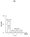
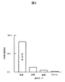
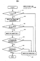
- PM emissions correlation graph by cycle in vehicle running cycle from cold to warm PM emission rate correlation graph by mode in the vehicle running cycle in cold state Control flow chart of one embodiment of the present invention
- FIG. 1 shows an overall configuration of an engine and an engine control apparatus according to an embodiment of the present invention.
- the engine is an in-cylinder direct injection type 4-cycle engine having an injection valve that directly injects fuel into the cylinder, and is an engine control unit (hereinafter referred to as ECU) composed of an MPU, I / O LSI, input / output circuit, and the like.
- ECU engine control unit
- An engine control device capable of comprehensively controlling the fuel injection amount, fuel pressure, ignition timing, knocking, and the like is provided.
- the engine and the engine control device detect the crank angle (position) and the rotation speed with the crank angle sensor 3, and the air amount measured directly or indirectly by the air flow sensor 4 or the intake pipe pressure sensor 5.
- the fuel corresponding to the above is injected from the injector 6 at an appropriate timing, and the ignition coil 7 is moved at the ignition timing retrieved from the charging timing calculated from the charging efficiency calculated from the air amount or the axis of the load value and the rotational speed. It is based on driving and igniting.
- the appropriate injection timing described above is set approximately once or a plurality of times during the intake stroke, is injected at a preset fuel pressure, and the injected fuel does not adhere to the inner wall surface of the cylinder as much as possible and is vaporized. It is easy to produce a homogeneous mixture.
- the set value of the ignition timing map is set so as to maximize the fuel consumption and output of the engine, and when it is determined that knocking is present based on the signal detected by the knock sensor 2, the ignition timing is corrected to be retarded. It is supposed to be.
- the engine coolant temperature sensor 8 is a sensor that detects the temperature of the engine before starting and after starting, and at the time of cold start, depending on the temperature of the engine, that is, the in-cylinder temperature at which fuel is injected, This is an important sensor for adjusting the fuel injection amount in consideration of the fuel adhering amount and the fuel vaporization delay, and can detect the warm-up state of the engine after starting.
- the engine lubricating oil temperature sensor 9 is provided mainly for operation compensation of a hydraulically driven variable valve timing control device (not shown in detail). That is, the control device detects the viscosity change due to the temperature of the lubricating oil. On the other hand, by using this sensor signal, it is possible to detect the warming-up state of the piston crown that cannot be estimated only by the engine cooling water temperature sensor described above. (Details will be described later).
- the electric throttle valve 10 is built in so as to detect engine torque required by a vehicle driver (hereinafter referred to as a driver) from a signal of an accelerator pedal opening sensor (not shown) and generate the required torque.
- a driver vehicle driver
- an accelerator pedal opening sensor not shown
- This is the main device of a so-called torque on demand control device that determines the throttle valve opening from an electric motor and an opening sensor.
- the compressor 11 and the exhaust turbine 12 are so-called turbochargers in which the respective wheels are integrally formed as a single unit.
- a turbine wheel in which the engine is operated at a high load and rotational force is given by high-temperature and high-pressure exhaust gas.
- the upstream side of the compressor 11 outside air, atmospheric pressure
- the volumetric efficiency of the air guided into the engine cylinder can be increased.
- the engine generated torque is increased by increasing the engine torque.
- the exhaust turbine 12 is provided with a so-called waste gate valve capable of adjusting the amount of exhaust gas guided to the turbine, so that the opening degree is adjusted so as to achieve a target supercharging pressure. It has become.
- the intercooler 13 is air-cooled, and when the engine is operating at a high load, the temperature of the high-temperature intake air supercharged by the supercharger is lowered by heat exchange with the outside air to reduce the occurrence of knocking. The charging efficiency of the introduced air is increased, and the supercharging effect is kept high. Note that, because of its function, it is general that the entire amount of intake air passes through the intercooler.
- an intercooler bypass passage 14 and an air passage switching control valve 15 capable of switching the intake air downstream of the supercharger to the intercooler 13 or the intercooler bypass passage 14 are provided. To do.
- Figure 2 shows a cycle of a traveling vehicle speed pattern, including acceleration and deceleration from start to start, using a vehicle equipped with a downsizing DI turbo engine with specifications for engine displacement, compression ratio, engine coolant and engine lubricant.
- PM emission amount of each cycle when the engine is operated until the end of the four cycles when the engine is warmed up is expressed as a percentage of the total of the four cycles.
- the engine cooling water temperature at the start is 25 ° C. (normal temperature), and the engine cooling water temperature at the end of one cycle is about 50 ° C.
- the PM emission ratio at that time is 70% of the total of four cycles. Has reached.
- the PM emission rate ratio in the subsequent cycles is about 10%, it can be seen that the PM emission rate is not affected by the engine cooling water temperature when the engine cooling water temperature passes through a cold state of about 50 ° C. or less. .
- the cold state of the engine is judged from the engine cooling water temperature and the engine lubricating oil temperature, and the temperature downstream of the intercooler 13, that is, the air that is guided into the engine cylinder
- the temperature downstream of the intercooler 13 that is, the air that is guided into the engine cylinder
- the amount of PM emission is larger than that in the warm state.
- the engine cylinder inner wall temperature is low, knocking is less likely to occur. Even if it raises, there is little bounce and it is convenient.
- the temperature detected by the engine cooling water temperature sensor 8 is basically referred to.
- a piston cooling device engine lubricating oil is placed on the back surface of the piston crown surface.
- a mechanism for injecting oil such as a piston with a cooling channel and an oil jet, is employed, the temperature of the piston crown is affected by the temperature of the engine lubricating oil. It is desirable to refer to it.
- the “temperature at which it is possible to determine that the engine is not in a warm-up state” described in claim 4 of the present invention is the control permission determination upper limit temperature, and if the engine cooling water temperature is set to about 50 ° C. as described above.
- the temperature when the temperature is set by the engine lubricating oil temperature, it may be set in view of the fact that the engine lubricating oil temperature is lower than the engine cooling water temperature, but in any case, for example, the PM described in FIG. It is necessary to adapt to the specification (warm-up characteristics) of the target vehicle using the emission evaluation method.
- the air downstream of the intercooler 13 is raised.
- the air is supercharged by the compressor 11 and the upstream air ( A method is adopted in which the downstream air whose temperature has risen relative to the outside air is guided into the engine cylinder without passing through the intercooler 13.
- intercooler 13 is a heat exchanger
- energy is necessary for the heat source, and if it can be obtained from waste energy such as exhaust gas and deceleration regenerative energy, there will be no impact on fuel consumption and output, but stable enjoyment of waste energy and system layout design will be possible. It is not realistic considering the difficulty and cost.
- an intercooler bypass passage 14 and an air passage switching control valve 15 are provided beside the intercooler 13, and when the engine is determined to be cold, the air downstream of the compressor 13 is bypassed by the intercooler bypass.
- the air passage switching control valve 15 is controlled so as to pass through the passage 14.
- the air passage switching control valve is driven by a DC motor according to a command from the ECM 1 and is controlled to a target opening position by an opening position sensor.
- the air passage switching control valve 15 is controlled to flow through the intercooler bypass passage 14 so that the air downstream of the compressor 11 is not cooled by the intercooler 13, but in the first place, The temperature downstream of the compressor 11 is not always supercharged.
- FIG. 3 shows the PM emission by classifying the driving mode in the driving pattern into “acceleration”, “steady”, “deceleration” and “idle” for the first cycle (engine cold state) among the driving patterns described in FIG. It is the graph which represented the quantity in the ratio which occupies for the whole cycle.
- the engine is operated at a high load as described in claims 5 to 6 "according to the predetermined range excluding the maximum load of the engine, that is, the acceleration operation that is not the maximum load".
- the air passage switching control valve 15 is controlled so that the air downstream of the compressor 11 passes through the intercooler bypass passage 14.
- the air passage switching control valve 15 is set so that the air downstream of the compressor 11 passes through the intercooler bypass passage 14 on the condition that the engine operating load is within a predetermined range excluding the maximum load. Is controlling.
- the “acceleration” mode in which the engine is operated at a relatively high load for example, when the air temperature upstream of the compressor 11 ( ⁇ outside air temperature) is about 25 ° C., it is caused by supercharging. Due to the temperature rise effect, the temperature downstream of the compressor 11 reaches about 50 ° C. to 75 ° C. (in the same vehicle, the higher the displacement, the higher the temperature), so that the air passes through the intercooler bypass passage 14 and enters the engine cylinder. By introducing it, the vaporization of the injected fuel is greatly promoted and the PM emission amount is reduced.
- the predetermined range is set to be equal to or lower than the upper limit value of the engine operating load, and various physical parameters (parameters) of the engine operating load such as an accelerator pedal opening, a throttle opening, and an intake pipe pressure can be considered.
- the estimated torque ( ⁇ actual torque) calculated by the torque-on-demand control apparatus is used as an index.
- the torque-on-demand control device calculates the required torque from the accelerator pedal opening, and takes into account the combustion state of the engine, the loss torque, and the like so that the required torque can be generated. Since the estimated torque is calculated as the feedback control parameter by adjusting the waste gate valve opening of the engine, it is convenient that the engine operating load state is expressed in real time.
- the upper limit value of the estimated torque may be set to about 80% of the target torque. More specifically, in the target engine, the occurrence of knocking or the downstream of the compressor 13 depends on the engine cold state described above. It is necessary to adjust the temperature while checking the temperature.
- the air temperature downstream of the intercooler is predicted to cause knocking.
- the control of the air passage switching valve 15 controls the intercooler 13. Since air is flowed through and cooled, the occurrence of knocking is suppressed.
- the “temperature at which knocking is predicted to occur” is set based on the result of confirming in advance the correlation between the temperature of the air led into the cylinder of the engine ( ⁇ intake pipe temperature) and the occurrence of knocking.
- the temperature detection may be performed based on the information of the temperature sensor built in the intake pipe pressure sensor 5.
- the “predetermined value of the retardation correction amount by knocking” is set so that the retardation correction amount is about 1 to 2 deg in the warm-up state knock control. What is necessary is just to set to 3-5 deg.
- the engine warm-up state determination unit 401 determines whether or not the engine is in a cold state based on the engine cooling water temperature or the engine lubricating oil temperature.
- the air passage switching control valve operating unit 3 407 switches the air passage switching control valve 15 so that the air downstream of the compressor 11 is guided to the intercooler 13 side and is terminated.
- the air passage switching control valve operation unit 1 402 moves to the engine load state determination unit 403 while maintaining the position of the air passage switching control valve 15 set at the previous end. .
- the engine load state determination unit 403 is in the maximum load state, End with the same operation.
- the air passage switching control valve operation unit 404 switches the position of the air passage switching control valve 15 so that the air downstream of the compressor 11 is guided to the intercooler bypass passage 14 side. .
- the intercooler downstream air temperature determination unit 406 further When it is determined that the air temperature downstream of the intercooler is equal to or higher than the temperature at which knocking is predicted, the air passage switching control valve operating unit 3 407 moves the position of the air passage switching control valve 15 to the compressor 11. Since switching is performed so that the downstream air is guided to the intercooler bypass passage 14 side, undesirable knocking is suppressed.
- the PM emission amount can be effectively suppressed while avoiding problems such as knocking under operating conditions with a large PM emission amount, and PM reduction control with high robustness is possible.
Landscapes
- Engineering & Computer Science (AREA)
- Chemical & Material Sciences (AREA)
- Combustion & Propulsion (AREA)
- Mechanical Engineering (AREA)
- General Engineering & Computer Science (AREA)
- Physics & Mathematics (AREA)
- Thermal Sciences (AREA)
- Combined Controls Of Internal Combustion Engines (AREA)
- Output Control And Ontrol Of Special Type Engine (AREA)
Abstract
L'objet de la présente invention est de proposer une technique efficace pour réduire des émissions de particules qui est hautement robuste et permet d'éviter des inconvénients tels qu'un cognement. Ce dispositif de commande de moteur, qui commande un moteur relié à un compresseur de suralimentation et un refroidisseur intermédiaire qui refroidit l'air en aval du compresseur de suralimentation, est pourvu d'un moyen de régulation de température destiné à réguler la température de l'air en aval du refroidisseur intermédiaire. Si la température de l'eau de refroidissement du moteur et/ou la température de l'huile de lubrification du moteur est inférieure ou égale à une température de consigne, le moyen de régulation de température procède à une régulation pour augmenter la température de l'air en aval du refroidisseur intermédiaire afin que cette dernière soit au moins égale à la température de l'air en amont du compresseur de suralimentation.
Priority Applications (1)
| Application Number | Priority Date | Filing Date | Title |
|---|---|---|---|
| JP2017526261A JP6452816B2 (ja) | 2015-06-29 | 2016-06-10 | エンジンの制御装置 |
Applications Claiming Priority (2)
| Application Number | Priority Date | Filing Date | Title |
|---|---|---|---|
| JP2015-129462 | 2015-06-29 | ||
| JP2015129462 | 2015-06-29 |
Publications (1)
| Publication Number | Publication Date |
|---|---|
| WO2017002578A1 true WO2017002578A1 (fr) | 2017-01-05 |
Family
ID=57608113
Family Applications (1)
| Application Number | Title | Priority Date | Filing Date |
|---|---|---|---|
| PCT/JP2016/067303 Ceased WO2017002578A1 (fr) | 2015-06-29 | 2016-06-10 | Dispositif de commande de moteur |
Country Status (2)
| Country | Link |
|---|---|
| JP (1) | JP6452816B2 (fr) |
| WO (1) | WO2017002578A1 (fr) |
Cited By (6)
| Publication number | Priority date | Publication date | Assignee | Title |
|---|---|---|---|---|
| JP2018141378A (ja) * | 2017-02-27 | 2018-09-13 | トヨタ自動車株式会社 | 内燃機関の制御装置 |
| JP2019152188A (ja) * | 2018-03-06 | 2019-09-12 | トヨタ自動車株式会社 | 内燃機関の燃料噴射時期制御装置 |
| JP2020537477A (ja) * | 2017-10-11 | 2020-12-17 | ローベルト ボツシユ ゲゼルシヤフト ミツト ベシユレンクテル ハフツングRobert Bosch Gmbh | 駆動機械を作動させる装置および方法 |
| CN119084136A (zh) * | 2024-08-23 | 2024-12-06 | 潍柴动力股份有限公司 | 基于中冷旁通机构的温度控制装置、方法及发动机 |
| CN119099580A (zh) * | 2024-09-30 | 2024-12-10 | 东风商用车有限公司 | 一种混动发动机启停保护方法及系统 |
| CN119616730A (zh) * | 2024-12-29 | 2025-03-14 | 中国重汽集团济南动力有限公司 | 一种发动机进气预热控制系统及方法 |
Families Citing this family (1)
| Publication number | Priority date | Publication date | Assignee | Title |
|---|---|---|---|---|
| CN114961980B (zh) * | 2022-06-20 | 2023-11-17 | 中国第一汽车股份有限公司 | 一种发动机进气温度分缸控制方法及系统 |
Citations (4)
| Publication number | Priority date | Publication date | Assignee | Title |
|---|---|---|---|---|
| JPS61125632U (fr) * | 1985-01-25 | 1986-08-07 | ||
| JPS62153517A (ja) * | 1985-12-26 | 1987-07-08 | Toyota Motor Corp | 内燃機関の吸気冷却装置 |
| JPH04136424A (ja) * | 1990-09-28 | 1992-05-11 | Toyota Motor Corp | 過給エンジンのインタークーラバイパス制御装置 |
| US20100286960A1 (en) * | 2009-05-07 | 2010-11-11 | Ringeisen Marc | Method and device for monitoring an intercooler bypass valve |
Family Cites Families (3)
| Publication number | Priority date | Publication date | Assignee | Title |
|---|---|---|---|---|
| JP2770480B2 (ja) * | 1989-09-30 | 1998-07-02 | いすゞ自動車株式会社 | 内燃機関の吸気装置 |
| JPH04136425A (ja) * | 1990-09-28 | 1992-05-11 | Mazda Motor Corp | エンジンの制御装置 |
| JP2009133249A (ja) * | 2007-11-30 | 2009-06-18 | Toyota Motor Corp | 内燃機関の吸気装置 |
-
2016
- 2016-06-10 WO PCT/JP2016/067303 patent/WO2017002578A1/fr not_active Ceased
- 2016-06-10 JP JP2017526261A patent/JP6452816B2/ja active Active
Patent Citations (4)
| Publication number | Priority date | Publication date | Assignee | Title |
|---|---|---|---|---|
| JPS61125632U (fr) * | 1985-01-25 | 1986-08-07 | ||
| JPS62153517A (ja) * | 1985-12-26 | 1987-07-08 | Toyota Motor Corp | 内燃機関の吸気冷却装置 |
| JPH04136424A (ja) * | 1990-09-28 | 1992-05-11 | Toyota Motor Corp | 過給エンジンのインタークーラバイパス制御装置 |
| US20100286960A1 (en) * | 2009-05-07 | 2010-11-11 | Ringeisen Marc | Method and device for monitoring an intercooler bypass valve |
Cited By (7)
| Publication number | Priority date | Publication date | Assignee | Title |
|---|---|---|---|---|
| JP2018141378A (ja) * | 2017-02-27 | 2018-09-13 | トヨタ自動車株式会社 | 内燃機関の制御装置 |
| JP2020537477A (ja) * | 2017-10-11 | 2020-12-17 | ローベルト ボツシユ ゲゼルシヤフト ミツト ベシユレンクテル ハフツングRobert Bosch Gmbh | 駆動機械を作動させる装置および方法 |
| JP7078716B2 (ja) | 2017-10-11 | 2022-05-31 | ローベルト ボツシユ ゲゼルシヤフト ミツト ベシユレンクテル ハフツング | 駆動機械を作動させる装置および方法 |
| JP2019152188A (ja) * | 2018-03-06 | 2019-09-12 | トヨタ自動車株式会社 | 内燃機関の燃料噴射時期制御装置 |
| CN119084136A (zh) * | 2024-08-23 | 2024-12-06 | 潍柴动力股份有限公司 | 基于中冷旁通机构的温度控制装置、方法及发动机 |
| CN119099580A (zh) * | 2024-09-30 | 2024-12-10 | 东风商用车有限公司 | 一种混动发动机启停保护方法及系统 |
| CN119616730A (zh) * | 2024-12-29 | 2025-03-14 | 中国重汽集团济南动力有限公司 | 一种发动机进气预热控制系统及方法 |
Also Published As
| Publication number | Publication date |
|---|---|
| JPWO2017002578A1 (ja) | 2017-12-21 |
| JP6452816B2 (ja) | 2019-01-16 |
Similar Documents
| Publication | Publication Date | Title |
|---|---|---|
| JP6452816B2 (ja) | エンジンの制御装置 | |
| US6571765B2 (en) | Control system for engine | |
| US9903322B2 (en) | Control device and control method for internal combustion engine with supercharger | |
| CN101578442B (zh) | 燃料喷射控制装置和燃料喷射控制方法 | |
| US20160305356A1 (en) | Control apparatus of internal combustion engine | |
| JP6350972B2 (ja) | エンジンの制御装置 | |
| US10024246B2 (en) | Method for controlling an engine braking device and engine braking device | |
| JP2009191745A (ja) | 内燃機関の制御装置 | |
| JP2006348799A (ja) | 内燃機関の制御装置 | |
| JP2006233898A (ja) | Egr装置 | |
| JP6288130B2 (ja) | エンジンの制御装置 | |
| US11536216B2 (en) | Systems and methods for an engine | |
| JP5045658B2 (ja) | 内燃機関の制御装置 | |
| JP2018193899A (ja) | 圧縮天然ガス機関の吸排気構造 | |
| JP2012246797A (ja) | 内燃機関の制御装置 | |
| JP2012087641A (ja) | 燃料噴射装置 | |
| JP6323798B2 (ja) | エンジンの制御装置 | |
| US9885293B2 (en) | Control apparatus of engine | |
| JP2013160182A (ja) | 内燃機関の制御装置 | |
| CN104160133B (zh) | 带增压器的内燃机的控制装置及控制方法 | |
| JP2017044173A (ja) | 内燃機関の制御装置 | |
| JP2017089585A (ja) | 車両の制御方法及び車両の制御装置 | |
| CN106930850B (zh) | 双燃料发动机系统及其控制方法、车辆 | |
| WO2014034695A1 (fr) | Dispositif de commande pour moteur diesel | |
| JP2017066892A (ja) | 内燃機関 |
Legal Events
| Date | Code | Title | Description |
|---|---|---|---|
| 121 | Ep: the epo has been informed by wipo that ep was designated in this application |
Ref document number: 16817687 Country of ref document: EP Kind code of ref document: A1 |
|
| ENP | Entry into the national phase |
Ref document number: 2017526261 Country of ref document: JP Kind code of ref document: A |
|
| NENP | Non-entry into the national phase |
Ref country code: DE |
|
| 122 | Ep: pct application non-entry in european phase |
Ref document number: 16817687 Country of ref document: EP Kind code of ref document: A1 |