WO2017002603A1 - Dispositif d'entraînement de moteur-roue - Google Patents
Dispositif d'entraînement de moteur-roue Download PDFInfo
- Publication number
- WO2017002603A1 WO2017002603A1 PCT/JP2016/067640 JP2016067640W WO2017002603A1 WO 2017002603 A1 WO2017002603 A1 WO 2017002603A1 JP 2016067640 W JP2016067640 W JP 2016067640W WO 2017002603 A1 WO2017002603 A1 WO 2017002603A1
- Authority
- WO
- WIPO (PCT)
- Prior art keywords
- gear
- motor
- wheel
- inner ring
- hub
- Prior art date
- Legal status (The legal status is an assumption and is not a legal conclusion. Google has not performed a legal analysis and makes no representation as to the accuracy of the status listed.)
- Ceased
Links
Images


Classifications
-
- B—PERFORMING OPERATIONS; TRANSPORTING
- B60—VEHICLES IN GENERAL
- B60K—ARRANGEMENT OR MOUNTING OF PROPULSION UNITS OR OF TRANSMISSIONS IN VEHICLES; ARRANGEMENT OR MOUNTING OF PLURAL DIVERSE PRIME-MOVERS IN VEHICLES; AUXILIARY DRIVES FOR VEHICLES; INSTRUMENTATION OR DASHBOARDS FOR VEHICLES; ARRANGEMENTS IN CONNECTION WITH COOLING, AIR INTAKE, GAS EXHAUST OR FUEL SUPPLY OF PROPULSION UNITS IN VEHICLES
- B60K7/00—Disposition of motor in, or adjacent to, traction wheel
-
- B—PERFORMING OPERATIONS; TRANSPORTING
- B60—VEHICLES IN GENERAL
- B60K—ARRANGEMENT OR MOUNTING OF PROPULSION UNITS OR OF TRANSMISSIONS IN VEHICLES; ARRANGEMENT OR MOUNTING OF PLURAL DIVERSE PRIME-MOVERS IN VEHICLES; AUXILIARY DRIVES FOR VEHICLES; INSTRUMENTATION OR DASHBOARDS FOR VEHICLES; ARRANGEMENTS IN CONNECTION WITH COOLING, AIR INTAKE, GAS EXHAUST OR FUEL SUPPLY OF PROPULSION UNITS IN VEHICLES
- B60K17/00—Arrangement or mounting of transmissions in vehicles
- B60K17/04—Arrangement or mounting of transmissions in vehicles characterised by arrangement, location or kind of gearing
- B60K17/14—Arrangement or mounting of transmissions in vehicles characterised by arrangement, location or kind of gearing the motor of fluid or electric gearing being disposed in, or adjacent to, traction wheel
-
- F—MECHANICAL ENGINEERING; LIGHTING; HEATING; WEAPONS; BLASTING
- F16—ENGINEERING ELEMENTS AND UNITS; GENERAL MEASURES FOR PRODUCING AND MAINTAINING EFFECTIVE FUNCTIONING OF MACHINES OR INSTALLATIONS; THERMAL INSULATION IN GENERAL
- F16H—GEARING
- F16H1/00—Toothed gearings for conveying rotary motion
- F16H1/02—Toothed gearings for conveying rotary motion without gears having orbital motion
- F16H1/04—Toothed gearings for conveying rotary motion without gears having orbital motion involving only two intermeshing members
- F16H1/06—Toothed gearings for conveying rotary motion without gears having orbital motion involving only two intermeshing members with parallel axes
-
- H—ELECTRICITY
- H02—GENERATION; CONVERSION OR DISTRIBUTION OF ELECTRIC POWER
- H02K—DYNAMO-ELECTRIC MACHINES
- H02K7/00—Arrangements for handling mechanical energy structurally associated with dynamo-electric machines, e.g. structural association with mechanical driving motors or auxiliary dynamo-electric machines
- H02K7/10—Structural association with clutches, brakes, gears, pulleys or mechanical starters
- H02K7/116—Structural association with clutches, brakes, gears, pulleys or mechanical starters with gears
-
- Y—GENERAL TAGGING OF NEW TECHNOLOGICAL DEVELOPMENTS; GENERAL TAGGING OF CROSS-SECTIONAL TECHNOLOGIES SPANNING OVER SEVERAL SECTIONS OF THE IPC; TECHNICAL SUBJECTS COVERED BY FORMER USPC CROSS-REFERENCE ART COLLECTIONS [XRACs] AND DIGESTS
- Y02—TECHNOLOGIES OR APPLICATIONS FOR MITIGATION OR ADAPTATION AGAINST CLIMATE CHANGE
- Y02T—CLIMATE CHANGE MITIGATION TECHNOLOGIES RELATED TO TRANSPORTATION
- Y02T10/00—Road transport of goods or passengers
- Y02T10/60—Other road transportation technologies with climate change mitigation effect
- Y02T10/64—Electric machine technologies in electromobility
Definitions
- the present invention relates to a technique for downsizing an in-wheel motor drive device.
- the in-wheel motor is arranged in the wheel (in wheel) and drives the wheel, there is no need to mount a drive source on the vehicle body unlike the conventional vehicle engine, and the internal space of the vehicle body can be used effectively. Can do.
- the drive source can be made smaller and lighter than a conventional vehicle engine.
- an in-wheel motor conventionally, for example, those described in Japanese Patent Application Laid-Open No. 2009-174492 (Patent Document 1) and Japanese Patent Application Laid-Open No. 2006-248417 (Patent Document 2) are known.
- a gear mechanism is provided on one side of the motor housing in the axial direction, and a wheel mounting board is disposed at the center of the gear mechanism.
- a flange is formed at one end in the axial direction of the wheel mounting board, and a large gear of the gear mechanism is provided at the other axial side of the wheel mounting board.
- a wheel is attached and fixed to the flange with a plurality of sets of bolts and nuts.
- the motor housing, the gear mechanism, and the flange of the wheel mounting plate are arranged in series with respect to the axis of the wheel mounting plate, the dimension in the axial direction of the vehicle wheel drive device is increased. For this reason, there is room for improvement in the axial dimension.
- the end of the in-wheel motor drive device protrudes from the wheel. If it does so, it will become difficult to accommodate a wheel and an in-wheel motor in the wheel housing provided in the vehicle body for engine cars. As a result, the vehicle body for the engine vehicle cannot be diverted to the electric vehicle equipped with the in-wheel motor drive device, which causes an increase in the cost of the electric vehicle.
- an object of the present invention is to provide a structure capable of shortening the axial dimension of an in-wheel motor drive device.
- an in-wheel motor drive device includes a hub inner ring having a wheel coupling portion on one side in the axial direction for coupling with a wheel, a hub outer ring surrounding an outer periphery of the hub inner ring, and a hub inner ring and a hub outer ring.
- a wheel hub bearing portion including a plurality of rolling elements disposed in an annular gap formed therebetween, and a small diameter that meshes with a large-diameter internal gear disposed on the inner periphery of the hub inner ring disposed in the inner space of the hub inner ring.
- a motor unit that is disposed on the other side in the axial direction of the wheel hub bearing unit and drives a small-diameter external gear.
- the motor part is arranged offset from the axis of the wheel hub bearing part in the direction perpendicular to the axis.
- the internal gear is provided on the inner periphery of the hub inner ring, and the hub inner ring is arranged so that the axis of the hub inner ring and the axis of the motor portion are different from each other, and the external gear is engaged with the internal gear of the hub inner ring.
- the axial position of the inner ring and the axial position of the external gear can be overlapped, and the axial dimension of the in-wheel motor drive device can be made smaller than before.
- the flange coupled with the wheel and the large gear of the gear mechanism are separated in the axial direction, and the large gear meshes with the pinion of the motor shaft.
- the wheel mounting board tilts to some extent, and the large gear hits the pinion and causes uneven wear. Therefore, in a preferred embodiment of the present invention, the above-described external gear is used as an output gear, and further provided is a reduction unit that reduces the motor rotation output from the motor unit and transmits it to the internal gear.
- the internal gear is formed on the inner periphery of the hub inner ring, the external gear of the speed reduction portion can be brought close to the wheel connecting portion of the hub inner ring, reducing the one-side contact due to the inclination, Uneven wear of gears can be prevented.
- the motor unit includes a motor main body that houses the rotor and the stator, a motor coupling shaft that is a member coupled to the rotor and projects from the motor main body toward the wheel hub bearing unit, and A motor rotation shaft gear provided on the outer periphery of the tip is included.
- the speed reduction unit further includes an input gear that is an external gear having a diameter larger than that of the motor rotation shaft gear and meshes with the motor rotation shaft gear, and an intermediate shaft that coaxially couples the input gear and the output gear of the speed reduction unit.
- the input gear is disposed between the wheel hub bearing portion and the motor body with respect to the axial position of the hub inner ring.
- the in-wheel motor drive device can be compactly arranged by disposing the large-diameter input gear that cannot be accommodated in the internal space of the hub inner ring while being shifted in the axial direction from the hub inner ring.
- a motor unit includes a motor main body that houses a rotor and a stator, a motor coupling shaft that is a member coupled to the rotor and projects from the motor main body toward the wheel hub bearing unit, and a motor rotation shaft A motor rotation shaft gear provided on the outer periphery of the tip is included.
- the speed reducer is an external gear having a larger diameter than the motor rotation shaft gear and meshes with the motor rotation shaft gear, a first intermediate shaft whose one end side is coupled to the center of the input gear, and a first intermediate shaft A first intermediate gear coupled to the other end side, a second intermediate gear meshing with the first intermediate gear, one end side coupled to the second intermediate gear, and the other end side transmitting the rotation of the second intermediate gear to the output gear. It further includes two intermediate shafts. The first intermediate gear and the second intermediate gear are arranged between the wheel hub bearing portion and the motor body with respect to the axial direction position of the hub inner ring.
- the in-wheel motor drive device can be compactly arranged by arranging the large-diameter intermediate gear that cannot be accommodated in the internal space of the hub inner ring while being shifted in the axial direction from the hub inner ring.
- the speed reduction unit may have a further intermediate shaft and intermediate gear in the rotation transmission path between the second intermediate shaft and the external gear. Or you may couple
- a preferred embodiment of the present invention relates to an axial line of a hub inner ring, and is arranged between an axial position of a wheel hub bearing portion and an axial position of a motor body, and is connected to a power line that supplies electric power from an external power source to the motor portion.
- the terminal box is further provided. According to this embodiment, since the terminal box is disposed between the wheel hub bearing portion and the motor body, the empty space between the wheel hub bearing portion and the motor body can be effectively utilized.
- the dimension in the axial direction of the in-wheel motor drive device can be shortened as compared with the conventional one. Therefore, the entire in-wheel motor drive device can be accommodated in the wheels, and the cost of the electric vehicle can be reduced by diverting a conventional vehicle body for an engine vehicle to the electric vehicle equipped with the in-wheel motor drive device. be able to.
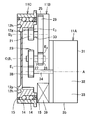
- FIG. 1 is a cross-sectional view showing an in-wheel motor drive apparatus according to an embodiment of the present invention.
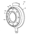
- 2 and 3 are perspective views showing the wheel hub bearing portion taken out from the embodiment.
- FIG. 2 shows a state when viewed from one axial side (wheel side), and
- FIG. 3 shows the other axial side (vehicle side). ) Represents the state.
- the in-wheel motor drive device 11 of this embodiment includes a motor unit 11A, a speed reduction unit 11B, and a wheel hub bearing unit 11C.
- the wheel hub bearing portion 11 ⁇ / b> C is a double row rolling bearing including a hub inner ring 12 that is a rotating member, a hub outer ring 13 that is a non-rotating member, and a plurality of rolling elements 14.
- the hub outer ring 13 surrounds the outer periphery of the hub inner ring 12, and the rolling elements 14 are arranged in an annular gap formed between the hub inner ring 12 and the hub outer ring 13.
- the annular gap is sealed with an annular seal 15 provided on the inner periphery of both ends of the hub outer ring 13.
- the rolling element 14 of this embodiment is a ball
- a seating surface 12p is formed on one side of the hub inner ring 12 in the axis O direction.
- the seating surface 12p is an annular flat surface perpendicular to the axis O.
- a plurality of bolt holes 12h are formed in the seating surface 12p at intervals in the circumferential direction.
- a wheel (not shown) is brought into contact with each seating surface 12p, and a bolt (not shown) is inserted into the wheel from one side in the axis O direction and screwed into each bolt hole 12h.
- An internal gear 12 g is provided on the inner periphery of the hub inner ring 12.
- the internal gear 12g is disposed on the other side of the hub inner ring 12 in the axis O direction.
- the seating surface 12p side is defined as one axial direction
- the internal gear 12g side is defined as the other axial direction side.
- the hub inner ring 12 has, on one side in the axis O direction, a disk-shaped wall portion 12w that closes the internal space of the hub inner ring 12, and a shaft portion 12s that stands up at the center of the wall portion 12w.
- the shaft portion 12s extends along the axis O.
- a rolling bearing 16 that rotatably supports the shaft portion 12s is provided in the inner space of the hub inner ring 12.
- the rolling bearing 16 is supported by the speed reduction part casing 25 of the speed reduction part 11B.
- the speed reducer 11B is a parallel shaft type speed reducer having an external gear 21, an intermediate shaft 22, an input gear 23, and a speed reducer casing 25 that accommodates these rotating elements.
- the external gear 21 is provided on one end side of the intermediate shaft 22, and the input gear 23 is provided on the other end side of the intermediate shaft 22.
- One end of the intermediate shaft 22 is rotatably supported by the speed reduction unit casing 25 via a rolling bearing 24.
- the other end of the intermediate shaft 22 is rotatably supported by the speed reduction unit casing 25 via a rolling bearing 26.
- the external gear 21 is a final gear of the reduction unit 11B, that is, an output gear.
- the external gear 21 and the input gear 23 are disposed between the rolling bearings 24 and 26, and are supported at both ends by these rolling bearings.
- the one end region of the speed reduction part casing 25 is fitted to the other end of the hub outer ring 13. Both fitting gaps are sealed by a seal 17.
- the seal 17 extends over the entire circumference of the hub outer ring 13.
- One end region of the speed reduction unit casing 25, one end region of the intermediate shaft 22, the external gear 21, and the rolling bearing 24 are disposed in the internal space of the hub inner ring 12.
- the external gear 21 having a relatively small inner diameter meshes with the internal gear 12g having a relatively large inner diameter.
- the other end region of the speed reduction unit casing 25, the other end region of the intermediate shaft 22, the input gear 23, and the rolling bearing 26 are disposed on the other side in the axial direction from the wheel hub bearing portion 11C.
- the axis B of the external gear 21, the intermediate shaft 22, and the input gear 23 extends in parallel with the axis O. That is, the speed reduction part 11B is arranged offset in the direction perpendicular to the axis O of the wheel hub bearing part 11C.
- the speed reduction part casing 25 of the speed reduction part 11B is coupled to the hub outer ring 13 described above.
- the input gear 23 is an external gear having a diameter larger than that of the external gear 21 and meshes with the motor rotation shaft gear 38 of the motor unit 11A.
- the motor rotation shaft gear 38 has a smaller diameter than the input gear 23. Therefore, the rotation of the motor rotation shaft gear 38 is decelerated by the speed reduction portion 11B and transmitted from the external gear 21 to the hub inner ring 12.
- the motor unit 11A is disposed on the other side in the axis O direction of the wheel hub bearing unit 11C, and includes a motor main body 31, a motor rotation shaft 34, and a motor rotation shaft gear 38.
- the motor body 31 includes a rotor 32 and a stator 33 centered on the axis A, and a cylindrical motor section casing 35 that houses the rotor 32 and the stator 33.
- the motor rotation shaft 34 is coupled to the rotor 32 and is disposed at the center of the motor unit casing 35. Both end portions of the motor rotating shaft 34 extending along the axis A are rotatably supported by both end portions of the motor portion casing 35 via rolling bearings 36 and 37.
- An end portion of the motor rotating shaft 34 protrudes from the motor portion casing 35 and is directed to the wheel hub bearing portion 11C.
- a motor rotation shaft gear 38 is provided on the outer periphery of the tip of the motor rotation shaft 34. That is, the motor rotation shaft gear 38 is disposed outside the motor unit casing 35.
- the rolling bearings 16, 24, 26, 36, and 37 that have been described so far are deep groove ball bearings, but may be bearings having other structures.
- the motor unit casing 35 is coupled to the speed reduction unit casing 25. With respect to the axis O, the hub outer ring 13, the speed reduction unit casing 25, and the motor unit casing 35 are arranged in this order.
- the motor rotation shaft gear 38 is accommodated in the speed reduction unit casing 25 and meshes with the input gear 23.
- the axis A of the motor part 11A, the axis B of the speed reduction part 11B, and the axis O of the wheel hub bearing part 11C are offset and arranged in parallel.
- the motor unit 11A and the speed reduction unit 11B are arranged at different circumferential positions around the axis O. Further, the motor part 11A, the speed reducing part 11B, and the wheel hub bearing part 11C are arranged in this order in the axial direction.
- the in-wheel motor drive device 11 is disposed on both sides in the vehicle width direction of the electric vehicle, and the axis O extends in the vehicle width direction of the electric vehicle.
- the wheel hub bearing portion 11C is disposed on the outer side in the vehicle width direction.
- the motor unit 11A is disposed on the inner side in the vehicle width direction.
- the large-diameter input gear 23 interposed between the hub inner ring 12 and the motor unit casing 35 is arranged offset to one side in the direction perpendicular to the axis as viewed from the axis O of the hub inner ring 12, the axis is perpendicular to the axis O. Space is left on the other side of the direction.
- a small-diameter motor rotating shaft gear 38 and a terminal box 39 are arranged in this space.
- the terminal box 39 is disposed adjacent to the motor main body 31 and is connected to an electric conductor extending from the coil of the stator 33.
- the terminal box 39 is disposed radially inward from the outer peripheral surface of the hub outer ring 13.
- a power line (not shown) extending from the external power source of the in-wheel motor drive device 11 is inserted and fixed in the terminal box 39.
- the motor rotation shaft 34 rotates, and this rotation is decelerated by the deceleration unit 11B and transmitted to the hub inner ring 12, and the hub inner ring 12 Rotates.
- the wheel hub bearing portion 11C surrounds the outer periphery of the hub inner ring 12 and the hub inner ring 12 having a seating surface 12p for connecting to the wheel and a bolt hole 12h (wheel connecting portion) on one side in the axial direction.
- Hub outer ring 13 a plurality of rolling elements 14 disposed in an annular gap formed between the hub inner ring 12 and the hub outer ring 13, and a large-diameter internal gear 12 g provided on the inner periphery of the hub inner ring 12.
- the small-diameter external gear 21 is disposed in the internal space of the hub inner ring 12 and meshes with the internal gear 12g.
- the motor portion 11A is arranged with respect to the axis O of the hub inner ring 12 and is offset in the direction perpendicular to the axis on the other side in the axial direction of the wheel hub bearing portion 11C, and drives the external gear 21.
- the axial direction dimension of the in-wheel motor drive device 11 can be shortened compared with the conventional in-wheel motor with which a motor part and a wheel hub bearing part are coaxially arrange
- the speed reduction part 11B includes the external gear 21, the speed reduction part 11B and the wheel hub bearing part 11C are arranged so as to overlap in the axial direction. Therefore, the axial direction dimension of the in-wheel motor drive device 11 can be made shorter than before.
- the motor unit 11A is a motor main body 31 that houses the rotor 32 and the stator 33, a member that is coupled to the rotor 32, and projects from the motor main body 31 toward the wheel hub bearing unit 11C. 34, and a motor rotation shaft gear 38 provided on the outer periphery of the front end portion of the motor rotation shaft 34.
- the reduction unit 11B is an external gear having a diameter larger than that of the motor rotation shaft gear 38, and includes an input gear 23 that meshes with the motor rotation shaft gear 38, an external gear 21, and an intermediate shaft 22 that coaxially couples the input gear 23. Including.
- the input gear 23 is disposed between the wheel hub bearing portion 11 ⁇ / b> C and the motor body 31 with respect to the position of the hub inner ring 12 in the axis O direction. Accordingly, the large-diameter input gear 23 can be disposed between the wheel hub bearing portion 11C and the motor portion 11A, and the small-diameter external gear 21 and the intermediate shaft 22 can be disposed so as to overlap the wheel hub bearing portion 11C.
- the axial direction dimension of the wheel motor drive device 11 can be made smaller than before.
- the terminal box 39 is connected between the wheel hub bearing portion 11C and the motor main body 31 with respect to the axial direction position of the hub inner ring 12 and connected to the power line for supplying power from the external power source to the motor portion 11A. Is further provided.
- the in-wheel motor drive device 11 can be reduced in size by effectively utilizing the empty space between the wheel hub bearing portion 11C and the motor body 31.
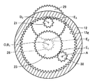
- FIG. 4 and 5 are schematic views showing another embodiment of the present invention.
- FIG. 4 shows a state when viewed in the direction perpendicular to the axis
- FIG. 5 shows a state when viewed in the direction of the axis.
- the same reference numerals are given to the configurations common to the above-described embodiments, and the description thereof will be omitted, and different configurations will be described below.
- the input gear 23 to the deceleration portion 11B is engaged with the motor shaft gear 38 at meshing point E 1 be the external gear of larger diameter than the motor shaft gear 38, one end side of the input gear 23 the first intermediate shaft 27 for coupling the center, first intermediate gear 28, second intermediate gear 29 that meshes with the first intermediate gear 28 in mesh point E 2 that binds the other end of the first intermediate shaft 27, one end side It further includes a second intermediate shaft 30 that is coupled to the second intermediate gear 29 and whose other end side transmits the rotation of the second intermediate gear 29 to the external gear 21.
- the first intermediate gear 28 is a relatively small-diameter external gear.
- the second intermediate gear 29 is an external gear having a relatively large diameter. Further, the second intermediate gear 29 is made larger in diameter than the external gear 21 on the speed reduction portion output side.
- External gear 21 is an internal gear 12g meshes with mesh point E 3.
- the second intermediate gear 29 overlaps the hub inner ring 12 when viewed in the axial direction.
- the first intermediate gear 28 and the second intermediate gear 29 are disposed between the wheel hub bearing portion 11 ⁇ / b> C and the motor body 31 so that the axial positions do not overlap.
- the axis B 1 of the input gear 23, the first intermediate shaft 27, and the first intermediate gear 28 coincides with the axis O or extends in parallel with an offset at a position close to the axis O.
- the axis B 2 of the second intermediate gear 29, the second intermediate shaft 30, and the external gear 21 extends in parallel with an offset at a position far from the axis O.
- the axes B 1 and B 2 extend in parallel with being offset from the axis of the motor unit 11A.
- the in-wheel motor drive can be made smaller than before.
- the in-wheel motor drive device according to the present invention is advantageously used in electric vehicles and hybrid vehicles.
- 11 In-wheel motor drive device 11A motor part, 11B deceleration part, 11C wheel hub bearing part, 12 hub inner ring, 12g internal gear, 12h bolt hole (wheel connecting part), 12p seating surface (wheel connecting part), 12s shaft Part, 12w wall part, 13 hub outer ring, 14 rolling element, 15 seal, 21 external gear (decelerator output gear), 22 intermediate shaft, 23 input gear (decelerator input gear), 25 reducer casing, 27 first Intermediate shaft, 28 First intermediate gear, 29 Second intermediate gear, 30 Second intermediate shaft, 31 Motor body, 32 Rotor, 33 Stator, 34 Motor rotation shaft, 35 Motor section casing, 38 Motor rotation shaft gear, 39 Terminal box .
Landscapes
- Engineering & Computer Science (AREA)
- Mechanical Engineering (AREA)
- General Engineering & Computer Science (AREA)
- Chemical & Material Sciences (AREA)
- Combustion & Propulsion (AREA)
- Transportation (AREA)
- Power Engineering (AREA)
- Arrangement Or Mounting Of Propulsion Units For Vehicles (AREA)
- Gear Transmission (AREA)
- Connection Of Motors, Electrical Generators, Mechanical Devices, And The Like (AREA)
Abstract
La présente invention concerne un dispositif (11) d'entraînement de moteur-roue comprenant : une partie (11C) palier de moyeu de roue qui comprend une bague intérieure (12) de moyeu ayant des parties (12h, 12p) d'accouplement de roue destinées à être accouplées à une roue, au niveau d'un côté dans la direction de l'axe, une bague extérieure (13) de moyeu entourant la périphérie extérieure de la bague intérieure de moyeu, et une pluralité de corps roulants (14) agencés entre la bague intérieure de moyeu et la bague extérieure de moyeu ; un engrenage (21) à denture externe ayant un petit diamètre qui est agencé dans l'espace intérieur de la bague intérieure de moyeu, et des engrenages présentant un engrenage (12g) à denture interne ayant un grand diamètre placé dans la périphérie intérieure de la bague intérieure de moyeu ; et une partie moteur (11A) qui est agencée au niveau de l'autre côté dans la direction de l'axe (O) de la partie palier de moyeu de roue, et entraîne l'engrenage à denture externe. En outre, la partie moteur est agencée de manière à être décalée vers la direction perpendiculaire à l'axe par rapport à l'axe de la partie palier de moyeu de roue.
Applications Claiming Priority (2)
| Application Number | Priority Date | Filing Date | Title |
|---|---|---|---|
| JP2015-133742 | 2015-07-02 | ||
| JP2015133742A JP2017013682A (ja) | 2015-07-02 | 2015-07-02 | インホイールモータ駆動装置 |
Publications (1)
| Publication Number | Publication Date |
|---|---|
| WO2017002603A1 true WO2017002603A1 (fr) | 2017-01-05 |
Family
ID=57608747
Family Applications (1)
| Application Number | Title | Priority Date | Filing Date |
|---|---|---|---|
| PCT/JP2016/067640 Ceased WO2017002603A1 (fr) | 2015-07-02 | 2016-06-14 | Dispositif d'entraînement de moteur-roue |
Country Status (2)
| Country | Link |
|---|---|
| JP (1) | JP2017013682A (fr) |
| WO (1) | WO2017002603A1 (fr) |
Cited By (1)
| Publication number | Priority date | Publication date | Assignee | Title |
|---|---|---|---|---|
| CN110154744A (zh) * | 2018-02-13 | 2019-08-23 | Ntn株式会社 | 轮内电动机驱动装置 |
Families Citing this family (1)
| Publication number | Priority date | Publication date | Assignee | Title |
|---|---|---|---|---|
| JP7642476B2 (ja) * | 2021-07-28 | 2025-03-10 | 株式会社クボタ | ハイブリッド動力伝達機構 |
Citations (3)
| Publication number | Priority date | Publication date | Assignee | Title |
|---|---|---|---|---|
| JPS49107065U (fr) * | 1973-01-12 | 1974-09-12 | ||
| JPS5887623U (ja) * | 1981-12-10 | 1983-06-14 | 日産自動車株式会社 | 産業車両用駆動装置 |
| JP2013209020A (ja) * | 2012-03-30 | 2013-10-10 | Honda Motor Co Ltd | 電動車両 |
-
2015
- 2015-07-02 JP JP2015133742A patent/JP2017013682A/ja active Pending
-
2016
- 2016-06-14 WO PCT/JP2016/067640 patent/WO2017002603A1/fr not_active Ceased
Patent Citations (3)
| Publication number | Priority date | Publication date | Assignee | Title |
|---|---|---|---|---|
| JPS49107065U (fr) * | 1973-01-12 | 1974-09-12 | ||
| JPS5887623U (ja) * | 1981-12-10 | 1983-06-14 | 日産自動車株式会社 | 産業車両用駆動装置 |
| JP2013209020A (ja) * | 2012-03-30 | 2013-10-10 | Honda Motor Co Ltd | 電動車両 |
Cited By (1)
| Publication number | Priority date | Publication date | Assignee | Title |
|---|---|---|---|---|
| CN110154744A (zh) * | 2018-02-13 | 2019-08-23 | Ntn株式会社 | 轮内电动机驱动装置 |
Also Published As
| Publication number | Publication date |
|---|---|
| JP2017013682A (ja) | 2017-01-19 |
Similar Documents
| Publication | Publication Date | Title |
|---|---|---|
| CN111120583B (zh) | 减速装置及机电设备 | |
| KR101538080B1 (ko) | 인휠 어셈블리 및 이를 구비하는 차량 | |
| JP2019094932A (ja) | 車両用駆動装置 | |
| US10744874B2 (en) | Hybrid vehicle and vehicle | |
| JP6160478B2 (ja) | ハイブリッド車両の駆動装置 | |
| CN109842240B (zh) | 用于机动车的动力设备以及车桥动力设备 | |
| CN105873783A (zh) | 用于混合动力车辆的驱动装置 | |
| CN106828076B (zh) | 具有轮边减速装置的电动轮毂 | |
| WO2017026258A1 (fr) | Dispositif d'entraînement de moteur pour véhicule | |
| WO2015163183A1 (fr) | Dispositif d'entraînement de véhicule | |
| CN102171063B (zh) | 轮毂电动机单元 | |
| JP6596897B2 (ja) | モータ駆動装置 | |
| US20180257485A1 (en) | Powertrain for a motor vehicle | |
| JP2013072528A (ja) | モータ駆動ユニット | |
| JP6781608B2 (ja) | インホイールモータ駆動装置 | |
| WO2017002603A1 (fr) | Dispositif d'entraînement de moteur-roue | |
| CN101208217A (zh) | 混合动力车辆的动力传递装置 | |
| CN107850186B (zh) | 轮内电动机驱动装置 | |
| JP6217660B2 (ja) | 車両の駆動装置 | |
| CN110406362A (zh) | 电动汽车及其动力总成 | |
| WO2021192812A1 (fr) | Dispositif d'entraînement de moteur-roue | |
| CN112664637A (zh) | 车辆驱动装置 | |
| JP6903534B2 (ja) | インホイールモータ駆動装置 | |
| WO2018073979A1 (fr) | Dispositif d'entraînement de moteur dans roue | |
| JP2020085026A (ja) | 車両用駆動伝達装置 |
Legal Events
| Date | Code | Title | Description |
|---|---|---|---|
| 121 | Ep: the epo has been informed by wipo that ep was designated in this application |
Ref document number: 16817712 Country of ref document: EP Kind code of ref document: A1 |
|
| NENP | Non-entry into the national phase |
Ref country code: DE |
|
| 122 | Ep: pct application non-entry in european phase |
Ref document number: 16817712 Country of ref document: EP Kind code of ref document: A1 |