WO2017002630A1 - 泡吐出ノズル及び泡吐出装置 - Google Patents
泡吐出ノズル及び泡吐出装置 Download PDFInfo
- Publication number
- WO2017002630A1 WO2017002630A1 PCT/JP2016/067883 JP2016067883W WO2017002630A1 WO 2017002630 A1 WO2017002630 A1 WO 2017002630A1 JP 2016067883 W JP2016067883 W JP 2016067883W WO 2017002630 A1 WO2017002630 A1 WO 2017002630A1
- Authority
- WO
- WIPO (PCT)
- Prior art keywords
- foam
- bubble
- discharge
- discharge port
- area
- Prior art date
- Legal status (The legal status is an assumption and is not a legal conclusion. Google has not performed a legal analysis and makes no representation as to the accuracy of the status listed.)
- Ceased
Links
Images





Classifications
-
- B—PERFORMING OPERATIONS; TRANSPORTING
- B05—SPRAYING OR ATOMISING IN GENERAL; APPLYING FLUENT MATERIALS TO SURFACES, IN GENERAL
- B05B—SPRAYING APPARATUS; ATOMISING APPARATUS; NOZZLES
- B05B7/00—Spraying apparatus for discharge of liquids or other fluent materials from two or more sources, e.g. of liquid and air, of powder and gas
- B05B7/0018—Spraying apparatus for discharge of liquids or other fluent materials from two or more sources, e.g. of liquid and air, of powder and gas with devices for making foam
- B05B7/0025—Spraying apparatus for discharge of liquids or other fluent materials from two or more sources, e.g. of liquid and air, of powder and gas with devices for making foam with a compressed gas supply
- B05B7/0031—Spraying apparatus for discharge of liquids or other fluent materials from two or more sources, e.g. of liquid and air, of powder and gas with devices for making foam with a compressed gas supply with disturbing means promoting mixing, e.g. balls, crowns
- B05B7/0037—Spraying apparatus for discharge of liquids or other fluent materials from two or more sources, e.g. of liquid and air, of powder and gas with devices for making foam with a compressed gas supply with disturbing means promoting mixing, e.g. balls, crowns including sieves, porous members or the like
-
- A—HUMAN NECESSITIES
- A47—FURNITURE; DOMESTIC ARTICLES OR APPLIANCES; COFFEE MILLS; SPICE MILLS; SUCTION CLEANERS IN GENERAL
- A47K—SANITARY EQUIPMENT; ACCESSORIES THEREFOR, e.g. TOILET ACCESSORIES
- A47K5/00—Holders or dispensers for soap, toothpaste or the like
- A47K5/14—Foam or lather making devices
-
- B—PERFORMING OPERATIONS; TRANSPORTING
- B05—SPRAYING OR ATOMISING IN GENERAL; APPLYING FLUENT MATERIALS TO SURFACES, IN GENERAL
- B05B—SPRAYING APPARATUS; ATOMISING APPARATUS; NOZZLES
- B05B1/00—Nozzles, spray heads or other outlets, with or without auxiliary devices such as valves, heating means
- B05B1/02—Nozzles, spray heads or other outlets, with or without auxiliary devices such as valves, heating means designed to produce a jet, spray, or other discharge of particular shape or nature, e.g. in single drops, or having an outlet of particular shape
-
- B—PERFORMING OPERATIONS; TRANSPORTING
- B05—SPRAYING OR ATOMISING IN GENERAL; APPLYING FLUENT MATERIALS TO SURFACES, IN GENERAL
- B05B—SPRAYING APPARATUS; ATOMISING APPARATUS; NOZZLES
- B05B1/00—Nozzles, spray heads or other outlets, with or without auxiliary devices such as valves, heating means
- B05B1/14—Nozzles, spray heads or other outlets, with or without auxiliary devices such as valves, heating means with multiple outlet openings; with strainers in or outside the outlet opening
-
- B—PERFORMING OPERATIONS; TRANSPORTING
- B05—SPRAYING OR ATOMISING IN GENERAL; APPLYING FLUENT MATERIALS TO SURFACES, IN GENERAL
- B05B—SPRAYING APPARATUS; ATOMISING APPARATUS; NOZZLES
- B05B7/00—Spraying apparatus for discharge of liquids or other fluent materials from two or more sources, e.g. of liquid and air, of powder and gas
- B05B7/0018—Spraying apparatus for discharge of liquids or other fluent materials from two or more sources, e.g. of liquid and air, of powder and gas with devices for making foam
-
- B—PERFORMING OPERATIONS; TRANSPORTING
- B05—SPRAYING OR ATOMISING IN GENERAL; APPLYING FLUENT MATERIALS TO SURFACES, IN GENERAL
- B05B—SPRAYING APPARATUS; ATOMISING APPARATUS; NOZZLES
- B05B7/00—Spraying apparatus for discharge of liquids or other fluent materials from two or more sources, e.g. of liquid and air, of powder and gas
- B05B7/24—Spraying apparatus for discharge of liquids or other fluent materials from two or more sources, e.g. of liquid and air, of powder and gas with means, e.g. a container, for supplying liquid or other fluent material to a discharge device
- B05B7/26—Apparatus in which liquids or other fluent materials from different sources are brought together before entering the discharge device
- B05B7/262—Apparatus in which liquids or other fluent materials from different sources are brought together before entering the discharge device a liquid and a gas being brought together before entering the discharge device
- B05B7/267—Apparatus in which liquids or other fluent materials from different sources are brought together before entering the discharge device a liquid and a gas being brought together before entering the discharge device the liquid and the gas being both under pressure
-
- B—PERFORMING OPERATIONS; TRANSPORTING
- B05—SPRAYING OR ATOMISING IN GENERAL; APPLYING FLUENT MATERIALS TO SURFACES, IN GENERAL
- B05B—SPRAYING APPARATUS; ATOMISING APPARATUS; NOZZLES
- B05B12/00—Arrangements for controlling delivery; Arrangements for controlling the spray area
- B05B12/08—Arrangements for controlling delivery; Arrangements for controlling the spray area responsive to condition of liquid or other fluent material to be discharged, of ambient medium or of target ; responsive to condition of spray devices or of supply means, e.g. pipes, pumps or their drive means
- B05B12/12—Arrangements for controlling delivery; Arrangements for controlling the spray area responsive to condition of liquid or other fluent material to be discharged, of ambient medium or of target ; responsive to condition of spray devices or of supply means, e.g. pipes, pumps or their drive means responsive to conditions of ambient medium or target, e.g. humidity, temperature position or movement of the target relative to the spray apparatus
- B05B12/122—Arrangements for controlling delivery; Arrangements for controlling the spray area responsive to condition of liquid or other fluent material to be discharged, of ambient medium or of target ; responsive to condition of spray devices or of supply means, e.g. pipes, pumps or their drive means responsive to conditions of ambient medium or target, e.g. humidity, temperature position or movement of the target relative to the spray apparatus responsive to presence or shape of target
Definitions
- the present invention relates to a foam discharge nozzle and a foam discharge apparatus including the same.
- Patent Document 1 There is known a foam discharge device in which liquid soap is mixed with gas and discharged as mousse-like foam (Patent Document 1).
- Patent Document 2 discloses a foam discharge in which a plurality of discharge ports are formed with a specific arrangement and diameter on a nozzle head of a foam pump-equipped container that discharges a liquid content from a nozzle in a foam shape by pressing the nozzle head. It has been proposed that a foam model imitating a character is formed by a single pressing operation by attaching an adapter.
- Patent Document 3 proposes a similar foam discharge adapter, in which a twisted foam model is formed by a single pressing operation.
- the present invention is a foam discharge nozzle of a foam discharge apparatus, wherein a foam generated by mixing a liquid with a gas is formed in a foam diffusion space supplied from a foam supply port located on the upper side, and at the bottom of the foam diffusion space Single or plural foam outlets.
- a foam diffusion space supplied from a foam supply port located on the upper side, and at the bottom of the foam diffusion space Single or plural foam outlets.
- the area of the bottom is wider than the area of the bubble supply port.
- the centroid of the bubble discharge port does not coincide with the centroid of the supply port projection unit that projects the bubble supply port onto the bottom in parallel with the central axis of the bubble diffusion space.
- the present invention is a foam discharge nozzle of a foam discharge apparatus, wherein a foam generated by mixing a liquid with a gas is formed in a foam diffusion space supplied from a foam supply port located on the upper side, and at the bottom of the foam diffusion space One or a plurality of foam outlets.
- the area of the bottom is wider than the area of the bubble supply port.
- the bubble discharge port does not overlap with the supply port projection unit that projects the bubble supply port onto the bottom portion in parallel with the central axis of the bubble diffusion space.
- the present invention provides a foam discharge device provided with the above-described foam discharge nozzle.
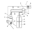
- FIG. 1 is a schematic diagram showing a schematic configuration of an embodiment of a foam discharge device of the present invention.
- FIG. 2 is a longitudinal sectional view of the foam discharge nozzle of the foam discharge apparatus shown in FIG.
- FIG. 3 is an exploded perspective view of the foam discharge nozzle of the foam discharge apparatus shown in FIG. 4A is a diagram showing an example of a foam discharge port formed at the bottom of the foam diffusion space, and is a cross-sectional view taken along the line IV-IV in FIG. 2 with the second porous body omitted.
- FIG. 5B are views showing another example of the foam discharge port formed at the bottom of the foam diffusion space (corresponding to FIG. 4A).
- FIG. 6A is a plan view of the bottom portion showing still another example of the foam discharge port formed at the bottom portion of the foam diffusion space
- FIG. 6B is the shape and arrangement shown in FIG. It is a top view which shows the planar view shape of the foam molded article obtained by this foam discharge port.
- Fig.7 (a) is a top view of this bottom part which shows another example of the foam discharge port formed in the bottom part of foam diffusion space
- FIG.7 (b) is a shape and arrangement
- Fig.8 (a) is a top view of this bottom part which shows another example of the foam discharge port formed in the bottom part of foam diffusion space
- FIG.8 (b) is a shape and arrangement
- Fig.9 (a) is a top view of this bottom part which shows another example of the foam discharge port formed in the bottom part of foam diffusion space
- FIG.9 (b) is a shape and arrangement
- FIG.9 (a) is a top view which shows the planar view shape of the foam molded article obtained by this foam discharge port.
- FIG. 10A is a plan view of the bottom portion showing still another example of the foam discharge port formed at the bottom portion of the foam diffusion space
- FIG. 10B is the shape and arrangement shown in FIG. It is a top view which shows the planar view shape of the foam molded article obtained by this foam discharge port.
- Fig.11 (a) is a top view of this bottom part which shows another example of the foam discharge port formed in the bottom part of foam diffusion space
- FIG.11 (b) is a shape and arrangement
- Patent Document 1 it is difficult to form a desired foam shape even if the formed foam is discharged.
- the technique proposed in Patent Document 2 is difficult to adjust the flow of foam to a plurality of discharge ports and the amount of discharge, and depending on the shape of the modeled object, it is possible to form the modeled foam in a desired shape.
- the technique of patent document 3 is difficult to apply to shapes other than the twisted three-dimensional shape.
- the present invention relates to a foam discharge nozzle and a foam discharge apparatus capable of stably forming a foam shaped article in a desired shape.
- FIG. 1 shows a schematic configuration of a foam discharge device 1 which is an embodiment of the foam discharge device of the present invention.
- the foam discharge device 1 is a foam discharge device including a foam discharge nozzle 3 which is an embodiment of the foam discharge nozzle of the present invention, and foam-like foam generated by mixing the liquid 20 with gas is discharged into the foam. It can be discharged from the nozzle 3.
- the liquid 20 is a liquid soap and the gas is air.
- a foam receiver 8 such as a human hand or a sponge under the foam discharge nozzle 3.
- FIG. 1 shows an example in which foam is ejected onto the palm of a foam receiver 8 that is a human hand, and a foam model B having a snowman-shaped contour is formed on the palm.
- the foam may be discharged onto the back of the hand.
- the foam receiver 8 is a part or object of the body that receives the foam discharged from the foam discharge nozzle 3, and may be a cloth, a cleaning sheet, a desk, etc. in addition to the human hand and sponge described above. .
- the foam discharge device 1 of the present embodiment is an electric foam discharge device, and discharges the liquid storage unit 2, the bubble discharge nozzle 3, and the liquid 20 in the storage unit 2.
- a liquid supply mechanism 4 that supplies the nozzle 3, a gas supply mechanism 5 that takes in ambient air (gas) and supplies it to the bubble discharge nozzle 3, and the liquid supply mechanism 4 and the gas supply when a predetermined signal is input
- a control unit 6 that automatically drives the mechanism 5 for a certain period of time is provided.
- the foam discharge device 1 of the present embodiment includes a non-contact sensor 7 that detects that a foam receiver 8 such as a human hand or a sponge is disposed under the foam discharge nozzle 3. When the detection signal when the bubble receiver 8 is detected is input, the control unit 6 automatically drives the liquid supply mechanism 4 and the gas supply mechanism 5 for a certain period of time.
- the storage unit 2 is composed of a container having a container body 21 and a cap 22 that can close the upper end opening of the container body 21 in an airtight manner.
- the liquid supply mechanism 4 includes a liquid pump 41 including an electric motor, a first connection pipe 42, and a second connection pipe 43, and stores while the liquid pump 41 is operating under the control of the control unit 6.
- the liquid 20 is sucked up from the inside of the unit 2 and the sucked liquid 20 is supplied to the bubble discharge nozzle 3.
- a centrifugal pump such as a spiral pump, a positive displacement pump such as a syringe pump, a gear pump, a diaphragm pump, a piezo pump, or the like is preferably used.
- the gas supply mechanism 5 includes an air pump 51 provided with an electric motor and an air supply pipe 52, and while the air pump 51 is operating under the control of the control unit 6, outside air from an intake hole (not shown) is supplied. Inhalation and inhaled air are supplied to the bubble discharge nozzle 3.
- the air pump 51 for example, a centrifugal pump such as a spiral pump, a positive displacement pump such as a syringe pump, a gear pump, a diaphragm pump, a piezo pump, or the like is preferably used.
- the first connection pipe 42, the second connection pipe 43, and the air supply pipe 52 for example, a tube made of rubber or synthetic resin, a metal pipe, or the like is used.
- the first connection pipe 42, the second connection pipe 43, and the air supply pipe 52 are preferably flexible.
- the control unit 6 includes an arithmetic processing unit, a storage unit, and a power supply unit, and is electrically connected to the electric motor of the liquid pump 41, the electric motor of the air pump 51, and the sensor 7.
- the arithmetic processing unit includes a microprocessor such as a CPU and MPU, the storage unit includes a ROM and a RAM, and stores programs and various data for causing the arithmetic processing unit to perform predetermined processing.
- the control unit 6 receives a signal detected by the sensor 7 when a foam receiver 8 such as a human hand or sponge is placed under the foam discharge nozzle 3, and controls each of the electric motors of the liquid pump 41 and the air pump 51. Control is performed so that driving is started.
- the power supply unit supplies power to the electric motors and control units of the liquid pump 41 and the air pump 51.
- the power supply unit is composed of a dry cell storage box, a secondary battery, or an internal or external AC-DC converter.
- various known sensors known as human sensors such as a pyroelectric sensor and a sensor composed of an infrared light emitting diode and an infrared light receiving diode, can be used.
- the foam discharge nozzle 3 in the foam discharge apparatus 1 includes a gas-liquid mixing unit 32 that mixes liquid and gas, and a first porous body 33 disposed downstream of the gas-liquid mixing unit 32.
- a bubble generating mechanism 31 is provided.
- the gas-liquid mixing unit 32 includes a merging unit 32a, a communication path 32b, and a mixing chamber 32c.
- the bubble discharge nozzle 3 in the bubble discharge apparatus 1 is comprised from each member shown in FIG.
- the foam discharge nozzle 3 includes a former case 34 that includes a cylindrical case body 35 and a cap 35d that is airtightly attached to an upper end opening of the cylindrical case body 35.
- the former case 34 has a through hole 35a penetrating vertically at the bottom center thereof, more specifically at the bottom center of the case main body 35.
- the former case 34 has an upper portion in the periphery surrounding the through hole 35a at the bottom portion of the former case 34.
- a cylindrical support portion 35b protruding toward the bottom and a connecting cylindrical portion 35c protruding downward are formed.
- the foam generation mechanism 31 in the foam discharge device 1 of the present embodiment includes a former member 36 and a cylindrical joint member 37, and the gas-liquid mixing unit 32 is formed by the former member 36 and the joint member 37. Yes.
- the confluence portion 32a of the gas-liquid mixing portion 32 is formed in an annular recess between the guide rod portion 36b of the former member 36 and the protruding portion 36c located around the lower portion thereof, and the communication path 32b is The through hole extending from the annular recess to the mixing chamber 32c is formed.
- the former member 36 includes a cylindrical portion 36 a that is fitted into the upper end portion of the cylindrical support portion 35 b of the former case 34, and the mixing chamber 32 c of the gas-liquid mixing portion 32 is a cylinder of the former member 36.
- the alignment guide rod portion 36b projects upward while being supported from the inner peripheral surface of the upper end portion of the cylindrical portion 36a.
- the joint member 37 includes a large-diameter cylindrical portion 37a, a small-diameter cylindrical portion 37c, and a connecting cylindrical portion 37d.
- the large diameter cylindrical portion 37 a has an inner diameter similar to the outer diameter of the cylindrical support portion 35 b of the former case 34.
- the small-diameter cylindrical portion 37c is continuously provided above the large-diameter cylindrical portion 37a via a stepped portion 37b.
- the connecting cylindrical portion 37d is continuously provided above the small diameter cylindrical portion 37c via a stepped portion.
- the joint member 37 inserts the guide rod portion 36b of the former member 36 into the small-diameter cylindrical portion 37c, and fits the large-diameter cylindrical portion 37a into the upper end portion of the cylindrical support portion 35b, whereby the cylindrical support portion 35b. Attached to.
- the guide rod portion 36 b of the former member 36 is inserted and arranged inside the small-diameter cylindrical portion 37 c of the joint member 37 to facilitate alignment between the former member 36 and the joint member 37.
- the joint member 37 is held by the case main body 35 in a state where the small-diameter cylindrical portion 37c penetrates the cap 22 up and down, and the connecting cylindrical portion 37d continuously provided above the small-diameter cylindrical portion 37c includes: A second connection pipe 43 of the liquid supply mechanism 4 is connected. Specifically, the outer peripheral surface of the second connection pipe 43 is in close contact with the inner peripheral surface of the connecting tubular portion 37d. In addition, a plurality of liquid circulation grooves are formed on the inner peripheral surface of the small-diameter cylindrical portion 37c so as to extend linearly in the vertical direction.
- the liquid supplied by the liquid supply mechanism 4 is transferred to the merging portion 32a through the liquid circulation groove on the inner peripheral surface of the small diameter cylindrical portion 37c, and merges with the gas at the merging portion 32a.
- the cap 35d is formed with a through-hole 35e penetrating vertically and a connecting cylindrical portion 35f extending upward from the periphery thereof.
- the connecting cylindrical portion 35f includes a supply pipe of the gas supply mechanism 5. 52 is connected. Specifically, the inner peripheral surface of the air supply pipe 52 is connected to the outer peripheral surface of the connecting tubular portion 35f.
- a gas flow groove is formed on the inner peripheral surface of the large-diameter cylindrical portion 37a so as to extend linearly in the vertical direction.
- the air supplied by the gas supply mechanism 5 flows in a space between the inner peripheral surface of the former case 34 and the outer peripheral surface of the joint member 37, and enters the gas flow groove from the lower end side of the joint member 37. Enters, flows in the gas flow groove and reaches the junction 32a.
- a plurality of gas flow grooves are formed to extend in the horizontal direction on the inner surface of the top surface portion of the large-diameter cylindrical portion 37a of the joint member 37, and a plurality of gas flow grooves are also formed on the inner surface of the stepped portion 37b in the vertical direction. Has been.
- the former member 36 is formed with a cylindrical projecting portion 36c projecting upward around the lower portion of the guide rod portion 36b.
- the protruding portion 36c is formed at a constant interval from the outer peripheral surface of the guide rod portion 36b, and an annular recess is formed between the guide rod portion 36b and the protruding portion 36c.
- the inside of the annular recess functions as the above-described joining portion 32a.
- a plurality of through holes penetrating up and down at predetermined intervals are formed at the bottom of the recess, and these through holes function as the communication path 32b described above.
- the gas flow groove described above also extends to the inner peripheral surface of the joint member 37 facing the cylindrical protrusion 36c, and the air that has entered the gas flow groove from the lower end side of the joint member 37 flows into the gas flow groove. It reaches the upper end position of the cylindrical projecting portion 36c through the groove, and is jetted from the joining portion 32a.
- the liquid merged with the gas in the merge section 32a is mixed with the gas while flowing through the merge section 32a, the communication path 32b, and the mixing chamber 32c, which is the gas-liquid mixing section 32 in the present apparatus 1, and produces coarse bubbles.
- the first porous body 33 disposed in the lower end opening of the cylindrical portion 36a of the former member 36 that is the outlet of the gas-liquid mixing portion 32 it becomes a foam-like bubble in which minute bubbles are gathered, It is sent out from the lower surface of the first porous body 33 to the foam discharge path 3a.
- the first porous body 33 a synthetic resin or metal mesh sheet, a sintered body of metal particles, a sponge-like molded body of a synthetic resin having a three-dimensional network structure, or the like can be used.
- various known methods such as heat sealing, ultrasonic sealing, adhesive, and fitting into the lower end portion of the large-diameter cylindrical portion 37a can be employed.
- the bubble discharge nozzle 3 in the present apparatus 1 includes a bubble diffusion space 3B below the first porous body 33 as shown in FIG. Further, the lower end opening 32d of the cylindrical portion 36a of the former member 36, which is the outlet of the gas-liquid mixing unit 32 described above, serves as the bubble supply port 11 for supplying bubbles to the bubble diffusion space 3B. More specifically, the lower end opening 32d covered with the first porous body 33 is the bubble supply port 11 in the present embodiment.
- the bubble supply port 11 is located above the bubble diffusion space 3 ⁇ / b> B, and bubbles generated by mixing the liquid 20 with gas are supplied into the bubble diffusion space 3 ⁇ / b> B through the bubble supply port 11.
- the bubble diffusion space 3B is a space for diffusing the bubbles supplied to the bubble diffusion space 3B in a direction intersecting with the bubble protruding direction T, and the bubbles supplied to the bubble diffusion space 3B pass through the bubble diffusion space 3B. After moving downward and diffusing also in the horizontal direction, the liquid is discharged downward from the foam discharge port 13 formed in the bottom 12 of the foam diffusion space 3B.
- the upper side and the upper side are the upper side and the upper side in the vertical direction in the usage state of the device 1
- the lower side and the lower side are the lower side in the vertical direction in the usage state of the device 1 and It is down.
- the bottom 12 of the bubble diffusion space 3B is formed at a portion facing the bubble supply port 11.
- the area of the bottom 12 of the bubble diffusion space 3 ⁇ / b> B is wider than the area of the bubble supply port 11.
- the area of the bottom 12 of the bubble diffusion space 3B is a plan view area of the upper surface facing the bubble diffusion space 3B and includes the area of the bubble discharge port 13.
- the first porous body 33 is provided in the bubble supply port 11, but the area of the bubble supply port 11 is the area of the lower end opening of the cylindrical portion 36 a of the former member 36, The area of the outlet 32d is the same.
- the bubble diffusion space 3 ⁇ / b> B in the apparatus 1 includes a lower space 3 ⁇ / b> C formed inside a horizontal diffusion promoting member 38 coupled below the former case 34, a first porous body 33, and a lower space. It consists of the upper space 3D located between 3C.
- the upper space 3D is a portion located below the first porous body 33 in the hollow portion formed inside the cylindrical body 35g forming the through hole 35a in the bottom portion of the former case 34.
- the cylindrical body 35g in the apparatus 1 is formed of the above-described cylindrical support portion 35b, the through hole 35a, and the connecting cylindrical portion 35c.
- the lower space 3C is a portion located below the connecting cylindrical portion 35c in the hollow portion formed inside the horizontal diffusion promoting member 38.
- the cross-sectional area of the plane perpendicular to the foam discharge direction T is larger than the area of the foam supply port 11 over the entire area in the height direction of the foam discharge nozzle 3. ing.
- the cross-sectional shape of the inner peripheral surface is circular, and the shape of the bottom portion 12 in plan view is also circular.
- the centroid 11c of the supply port projection unit 11A overlaps the center of the bubble diffusion space 3B having a circular cross-sectional shape.
- the horizontal diffusion promoting member 38 has an outer peripheral surface having a larger diameter than the outer peripheral surface of the former case 34, and has a hollow portion penetrating the horizontal diffusion promoting member 38 in the vertical direction. At the upper end portion of the horizontal diffusion promoting member 38, there is a connecting tubular portion 38b protruding so as to surround the hollow portion, and the connecting tubular portion of the former case 34 is provided inside the connecting tubular portion 38b. The portion 35c is connected to the lower portion of the former case 34 by fitting.
- the lower space 3C formed inside the horizontal diffusion promoting member 38 has an inner peripheral surface having a larger inner diameter at the lower end than at the upper end, and a cross-sectional area by a plane orthogonal to the foam discharge direction T expands from the upper side to the lower side. is doing. Further, the discharge port forming member 39 is fitted and fixed to the lower end portion of the hollow portion of the horizontal diffusion promoting member 38.
- the lower space 3C in the present embodiment includes a cross-sectional area enlarged portion 38c in which a cross-sectional area by a plane orthogonal to the foam discharge direction T gradually expands from above to below, and a cross-sectional area by a plane orthogonal to the foam discharge direction T. Has a constant cross-sectional area non-change portion 38d in the vertical direction. In the present embodiment, also in the upper space 3D, the cross-sectional area by a plane orthogonal to the bubble discharge direction T is constant in the vertical direction.
- the cross-sectional shape of the bubble diffusion space 3B, and the shape of the former case 34 and the horizontal diffusion promoting member 38 for forming the bubble diffusion space 3B are not limited to the shape of the present embodiment. It can be arbitrarily designed in consideration of the design and the amount of foam discharged.
- the cross-sectional area by a plane orthogonal to the foam discharge direction T may gradually increase from the upper side to the lower side, and the lower space 3C may not include the cross-sectional area non-changing portion 38d.
- the outer side of the cross-sectional area enlarged portion 38c of the horizontal diffusion promoting member 38 may have a shape that gradually increases in the same manner as the shape of the hollow portion.
- a discharge port forming member 39 is fitted and fixed to the lower end portion of the horizontal diffusion promoting member 38.
- the bubble diffusion space 3B in the present embodiment is a space from the lower surface of the first porous body 33 disposed at the outlet of the gas-liquid mixing unit 32 to the upper surface of the discharge port forming member 39, and is orthogonal to the bubble discharge direction T.
- the cross-sectional area by the plane to be is a part larger than the area of the bubble supply port 11.
- the bubble discharge direction T is a direction parallel to the central axis of the bubble diffusion space 3B.
- the direction parallel to the central axis of the bubble diffusion space 3B is, for example, when the bubble diffusion space 3B has a rotating body shape such as a columnar shape or a conical shape, the bubble discharge direction T is the rotation of the rotating body.
- the direction is parallel to the central axis of the rectangular tube.
- the direction parallel to the central axis of the bubble diffusion space 3B is relative to the upper surface of the bottom 12 of the bubble diffusion space 3B.
- the foam discharge device 1 is preferably used with the foam discharge direction T of the foam discharge nozzle 3 aligned with the vertical direction X.
- the bubble discharge direction from the outlet 32d of the gas-liquid mixing unit 32 to the bubble diffusion space 3B is also the bubble discharge direction T, and preferably coincides with the vertical direction X.
- the direction from the upper side to the lower side which is the traveling direction of the liquid 20 and the foam, is the vertical direction.
- the expression “matches the vertical direction” includes the case where the bubble discharge direction T is parallel to the vertical direction and the bubble discharge direction T is inclined with respect to the vertical direction, but the inclination angle is within 5 °. Is included.
- shaft corresponds with the structural member of the foam discharge nozzle 3 of this embodiment.
- the maximum value of the cross-sectional area of the bottom 12 and the plane orthogonal to the bubble discharge direction T is preferably twice or more, more preferably 10 times the area of the bubble supply port 11, respectively. Or more, more preferably 50 times or more, preferably 1000 times or less, more preferably 200 times or less, still more preferably 100 times or less, and preferably 2 times or more and 1000 times or less, more preferably 10 times or more. It is 200 times or less, More preferably, it is 50 times or more and 100 times or less.
- the maximum value of the cross-sectional area by the plane perpendicular to the area of the bottom portion 12 and the bubble discharge direction T is preferably 0.5 cm 2 or more, more preferably 2.8 cm 2 or more. It is preferably 300 cm 2 or less, more preferably 30 cm 2 or less.
- the maximum value of the cross-sectional area of the bubble diffusion space 3B is the cross-sectional area of the portion where the cross-sectional area of the bubble diffusion space 3B is maximized by a plane orthogonal to the foam discharge direction T.
- This is the cross-sectional area of the cross-sectional area non-changing portion 38d.
- the bubble diffusion space 3 ⁇ / b> B has a portion having a maximum cross-sectional area immediately before the portion adjacent to the bubble discharge port 13 or the second porous body 40.
- the discharge port forming member 39 is a member that forms the foam discharge port 13 having a predetermined shape in the bubble discharge nozzle 3, and the discharge port forming member 39 has, for example, the shape shown in FIG. 4 on the bottom 12 of the bubble diffusion space 3B. And a plurality of foam outlets 13 arranged are formed.
- the bubble discharge port 13 penetrates the discharge port forming member 39 that forms the bottom 12 of the bubble diffusion space 3B in the thickness direction.
- the shape and arrangement of the bubble discharge ports 13 are preferably the same over the entire area in the thickness direction of the discharge port forming member 39.
- the bubble diffusion space 3B preferably has a flat surface directed toward the bubble diffusion space 3B around the bubble discharge port 13 from the viewpoint of diffusing foam-like bubbles along the bottom portion 12.
- the upper surface 12a of the bottom 12 of the bubble diffusion space 3B preferably extends in a direction perpendicular to the bubble discharge direction T, and as in the present embodiment, an annular continuous plane surrounding the bubble discharge port 13 14 is preferable.
- Fig.4 (a) two foams mutually spaced apart as the foam discharge port 13 in the bottom part 12 of the bubble diffusion space 3B.
- Discharge ports 13a and 13b are formed.
- the two bubble discharge ports 13a and 13b are supplied by projecting the aforementioned bubble supply port 11 onto the bottom 12 of the bubble diffusion space 3B in parallel with the central axis of the bubble diffusion space 3B. It does not overlap with the centroid 11c of the mouth projection unit 11A, and each centroid 13c of the two bubble discharge ports 13a and 13b also overlaps with the supply port projection unit 11A as shown in FIG. 4A. Not.
- centroid of the bubble discharge port in the case of having a plurality of bubble discharge ports spaced apart from each other is the centroid of each bubble discharge port.
- the centroid is obtained from the shape of each foam outlet when the bottom of the foam diffusion space is viewed in plan. As shown in FIG. 4, when the shape of the foam outlet is circular, the center of the circle is the centroid.
- the centroid in the case of a non-circular shape can be easily obtained by using commercially available CAD or drawing creation software.
- the foam discharge apparatus 1 of this embodiment as shown to Fig.4 (a), several foam discharge outlets 13a and 13b formed in the bottom part 12 of the bubble diffusion space 3B supply all of them. It does not overlap with the mouth projection unit 11A.
- the supply port projection unit 11A is a portion obtained by projecting the opening shape of the bubble supply port 11 onto the bottom 12 in parallel with the central axis of the bubble diffusion space 3B. In FIG. 4A, the supply port projection unit 11A It is an area.
- the bubble discharge direction T, the direction parallel to the central axis of the bubble diffusion space 3B, and the vertical direction X are parallel, and the diameter and area of the supply port projection unit 11A are the same as the bubble supply port 11.
- the diameter and the opening area of the lower end opening 32d of the cylindrical portion 36a of the former member 36 are the same. Moreover, when the bubble discharge port 13 and the supply port projection part 11A overlap only in the periphery of each other, it is assumed that the bubble discharge port 13 and the supply port projection part 11A do not overlap.
- the foam discharge device 1 of the present embodiment when a foam receiver 8 such as a human hand or a sponge is placed under the foam discharge nozzle 3, the sensor 7 detects it and sends a detection signal to the control unit 6. send. Upon receiving the signal from the sensor 7, the control unit 6 drives the liquid supply mechanism 4 and the gas supply mechanism 5 for a predetermined time. Accordingly, a certain amount of liquid is supplied to the bubble discharge nozzle 3 by the liquid supply mechanism 4, and a certain amount of air is supplied to the bubble discharge nozzle 3 by the gas supply mechanism 5. A certain amount of foam-like foam is discharged from a discharge port onto a foam receiver 8 such as a human hand or a sponge.
- foam generated by mixing the liquid 20 with gas is supplied from the foam supply port 11 into the foam diffusion space 3B, and the foam travels downward in the foam diffusion space 3B.
- the plurality of bubble discharge ports 13a and 13b are arranged so that the respective centroids 13c do not overlap the centroid 11c of the supply port projection unit 11A, some of the bubbles are It strikes a portion other than the bubble discharge port 13 and diffuses in the horizontal direction along the bottom portion 12.
- the foam-like foam supplied into the foam diffusion space 3B is discharged onto the foam receiver 8 such as a palm or sponge at a speed averaged from each part of the plurality of foam discharge ports 13a and 13a.
- the shape and arrangement of the foam outlet 13 it is possible to stably form the foam shaped object B having the desired shape outline on the palm of the human hand, the back of the hand, the surface of the sponge, and the like.
- the foam-shaped bubbles are bubbled at a more averaged speed.
- the moldability of the foamed molded article B that is discharged onto the receiver 8 and has a predetermined plan view shape is further improved.
- the individual foam discharge ports 13a and 13b are also arranged so as not to overlap the supply port projection unit 11A, the foam-like foam supplied into the foam diffusion space 3B is more reliably a plurality of foams. It discharges on the bubble receiving body 8 such as a palm or a sponge at a speed averaged from each part of the discharge ports 13a and 13a. Therefore, the moldability of the foam shaped article B having a predetermined plan view shape is further improved.
- FIG. 4B is a diagram showing a foamed object B having a snowman-like shape in plan view, which is formed on the foam receiver 8 by the foam discharge ports 13 having the shape and arrangement shown in FIG. .
- the foamed object B having a snowman-like shape in plan view has a large area part b1 and a small area part b2 having different sizes when seen in a plan view, and the large area part b1 mainly includes two bubbles.
- the small area portion b2 is mainly formed by bubbles discharged from the first discharge port 13a, which is one of the discharge ports 13a, 13b, and the second discharge port, which is the other of the two bubble discharge ports 13a, 13b. It is formed by bubbles discharged from the outlet 13b.
- the foam when forming the foam shaped article B having the large area part b1 and the small area part b2 having different sizes when viewed in plan, the foam is a viscoelastic body and is close to the supply port projection part 11A. Since a large amount is easily discharged from the bubble discharge port, as shown in FIG. 4A, the first discharge port 13a that mainly discharges the foam that forms the large area portion b1 and the centroid 11c of the supply port projection unit 11A It is also preferable that the distance La is shorter than the distance Lb between the second discharge port 13b that mainly discharges the bubbles that form the small area portion b2 and the centroid 11c of the supply port projection unit 11A.
- the first discharge port 13a and the second discharge port 13b may have an area of the first discharge port 13a larger than that of the second discharge port 13b, but the area of the first discharge port 13a and the second discharge port The area of 13b can be made the same.
- the area of the 1st discharge port 13a and the area of the 2nd discharge port 13b are made the same, about the discharge port of the direction which wants to be made into the large area part of the foam molded article B, it is with the centroid 11c of the supply port projection part 11A. Increase the distance between.
- the distance Lb is made longer than the distance La, or the distance La is made shorter than the distance Lb, thereby discharging bubbles forming the large area portion b1.
- the area of the first discharge port 13a can be made smaller than the area of the second discharge port 13b.
- the first discharge that simply discharges the foam that forms the large area part b1. It is also possible to adopt a method in which the area of the outlet 13a is made larger than the area of the second discharge port 13b that discharges bubbles forming the small area part b2. It is possible to use both the method of changing the area and the method of changing the distance.
- the foam When forming a foam shaped article B having a large area part b1 and a small area part b2 having different sizes when seen in a plan view, the foam is a viscoelastic body and is directed to a direction in which it flows easily and an outlet with less resistance. 10 (a) and 10 (b), the distance between the first discharge port 13a that discharges the bubbles forming the large area portion b1 and the centroid 11c of the supply port projection unit 11A.
- La is shorter than the distance Lb between the first discharge port 13b that discharges the bubbles forming the small area portion b2 and the centroid 11c of the supply port projection unit 11A, the first relative to the area Sb of the second discharge port 13b.
- the ratio (Ga / Gb) of the area Gb of the large area portion b1 to the area Gb of the small area portion b2 is larger than the ratio (Sa / Sb) of the area Sa of the discharge port 13a.
- the area Sa of the first discharge port 13a is equal to the area Sb of the first discharge port 13b as shown in FIG. Is smaller than the distance Lb between the first discharge port 13b and the centroid 11c of the supply port projection unit 11A.
- the ratio of the area Gb of the large area part b1 to the area Gb of the small area part b2 (Ga / Gb) than the ratio of the area Sa of the first outlet 13a to the area Sb of the second outlet 13b (Sa / Sb). ) Increases and the first discharge port 13a having a small area Sa discharges bubbles forming the large area portion b1.
- the first discharge port 13a and the small area portion b2 for discharging the bubbles forming the large area portion b1 are formed.
- the second discharge port 13b for discharging bubbles is preferably formed to satisfy the following formula (1).
- Ga is the area of the large area portion
- Gb is the area of the small area portion
- Sa is the area of the first discharge port 13a
- La is the centroid 13ca of the first discharge port 13a and the supply port projection unit 11A.
- ⁇ is a real number not less than 0.1 and not more than 2.
- ⁇ is a coefficient determined in consideration of the ease of flow of bubbles, and varies depending on the liquid 20 used, the bubble generation mechanism 31 and the like. ⁇ is obtained in advance from the liquid 20 to be used and the foam formed by the foam generating mechanism 31 and the like as follows.
- a second discharge port 13b having an area Sb that is twice the area Sa of the first discharge port 13a and the first discharge port 13a is arranged at the same distance from the centroid 11c of the supply port projection unit 11A of the bubble supply port 11.
- a nozzle 3 is prepared.
- the foam shaped object B is discharged from the first discharge port 13a and the second discharge port 13b, and the area Ga of the large area part b1 and the area Gb of the small area part b2 are measured.
- the measurement result is applied to Equation (1), and ⁇ is calculated.
- FIG. 5A and FIG. 5B show another example of the foam discharge port 13 formed at the bottom 12 of the foam diffusion space 3B.
- a plurality of main discharge portions 113a and 113b are connected to the bottom portion 12 of the bubble diffusion space 3B as a bubble discharge port 13 through slit-like narrow boundary discharge portions 113d.
- a bubble discharge port 13d having the above configuration is formed.
- the centroid 13c of the bubble discharge port 13d does not overlap with the centroid 11c of the supply port projection unit 11A, and the centroid 13c of the bubble discharge port 13d is as shown in FIG. As shown to a), it does not overlap with supply port projection part 11A.
- FIG. 5A the centroid 13c of the bubble discharge port 13d does not overlap with supply port projection part 11A.
- the bubble discharge port 13d does not overlap the supply port projection unit 11A.
- the centroid 13c of the bubble discharge port 13d is the center of gravity of the plate-like body assuming a plate-like body having the same shape and size as the bubble discharge port 13 and a uniform density at the position of the bubble discharge port 13.
- the centroid 13c of the bubble discharge port 13d can also be obtained by the following method. That is, the centroid 13c of the bubble discharge port 13d is not the centroid of each of the bubble discharge ports 113a and 113b, but two arbitrary axes perpendicular to each other are defined on the plane where the bubble discharge port 13d exists.
- the positions of the centroids of the discharge units 113a and 113b and the boundary discharge unit 113d are (Ax, Ay) (Bx, By) (Cx, Cy) (the same applies hereinafter), the bubble discharge units 113a and 113b, and the boundary discharge unit 113d.
- SA is the area of SA, SB, SC (the same applies hereinafter)
- S-all is the total area of the bubble discharge port 13d
- the coordinates of the centroid 13c are (Mx, My). It is a coordinate (Mx, My) that satisfies (Expression).
- SA ⁇ Ax + SB ⁇ Bx + SC ⁇ Cx +... S-all ⁇ Mx (1 set)
- SA x Ay + SB x By + SC x Cy + ... S-all x My (2 formulas)
- the centroid 13c of the bubble discharge port 13d can be easily obtained by using commercially available CAD or drawing creation software.
- FIG. 5B a configuration in which a plurality of main discharge portions 113a and 113b are connected to the bottom portion 12 of the bubble diffusion space 3B as a bubble discharge port 13 via a narrow boundary discharge portion 113e.
- the foam discharge port 13e which has is formed.
- the centroid 13c of the bubble discharge port 13e does not overlap with the centroid 11c of the supply port projection unit 11A, and the centroid 13c of the bubble discharge port 13e is not shown in FIG. As shown to b), it does not overlap with supply port projection part 11A.
- FIG. 5B a configuration in which a plurality of main discharge portions 113a and 113b are connected to the bottom portion 12 of the bubble diffusion space 3B as a bubble discharge port 13 via a narrow boundary discharge portion 113e.
- the foam discharge port 13e which has is formed.
- the centroid 13c of the bubble discharge port 13e does not overlap with the centroid 11c of the supply port projection unit 11A, and the centroid 13c of the bubble discharge port 13e
- the bubble discharge port 13e partially overlaps the supply port projection unit 11A, but the bubble discharge port 13e is also arranged so as not to overlap the supply port projection unit 11A. It is preferable.
- the area where the bubble discharge port 13e and the supply port projection unit 11A overlap is preferably 0 to 30%, more preferably 0 to 10%, of the area of the bubble discharge port 13e.
- the centroid 13c of the bubble discharge port 13e is obtained in the same manner as the centroid 13c of the bubble discharge port 13d described above. However, since the boundary discharge portion 113e has no area, the centroid of the boundary discharge portion 113e is ignored. Ask. Further, the cross-sectional shape of the bubble discharge port 13e is a shape in which the circular main discharge portions 113a and 113b overlap each other, and the main discharge portions 113a and 113b are not completely circular, but are each circular and positioned at the centroid. Determine. The centroid 13c of the bubble discharge port 13e can be easily obtained even by using commercially available CAD or drawing creation software.
- Bubble discharge ports 13d and 13e having the shape and arrangement shown in FIG. 5 (a) or FIG. 5 (b) are formed at the bottom 12 of the bubble diffusion space 3B of the bubble discharge nozzle 3 of the bubble discharge device 1 of the embodiment described above. Even in the case, the foam-like foam supplied in the foam diffusion space 3B is discharged onto the foam receiver 8 such as a palm or a sponge at a speed averaged from each part of the foam discharge ports 13d and 13e. It is possible to stably form a foam shaped article B having a desired contour on the foam receiver 8.
- the width of the boundary discharge portions 113d and 113e is preferably Is 0.1 mm to 5.0 mm, more preferably 0.5 mm to 2.0 mm.
- the width of the slit-like boundary discharge portion 113d which is the length in the direction orthogonal to the direction in which the boundary discharge portion 113d extends, is the width of the boundary discharge portion 113d.
- the foam model shown in FIG. 4 (b) is formed on the foam receiver 8.
- the large-area part b1 having a large size when viewed in plan of the snowman-like foam shaped object B is mainly from the first discharge part 113a which is one of the two main discharge parts 113a and 113b.
- the small area part b2 formed by the discharged bubbles and having a size in plan view smaller than the large area part b1 is mainly discharged from the second discharge part 113b which is the other of the main discharge parts 113a and 113b. It is formed by bubbles.
- the foam when forming the foam shaped article B having the large area part b1 and the small area part b2 having different sizes when seen in a plan view, the foam is a viscoelastic body, and is easy to flow and has little resistance. From the viewpoint of flowing toward the outlet, as shown in FIG. 5A, between the first discharge portion 113a that mainly discharges the foam that forms the large area portion b1 and the centroid 11c of the supply port projection portion 11A. It is preferable that the distance La is shorter than the distance Lb between the second discharge part 113b that discharges bubbles mainly forming the small area part b2 and the centroid 11c of the supply port projection part 11A.
- the area of the first discharge part 113a and the second discharge part 113b may be larger than the area of the second discharge part 113b, but the area of the first discharge part 113a and the second discharge part 113b may be larger.
- the area of 113b may be the same.
- the difference between the distance Lb and the distance La can be increased so that the area of the first ejection part 113a can be made smaller than the area of the second ejection part 113b.
- the first discharge that simply discharges the foam that forms the large area part b1
- the area of the portion 113a is made larger than the area of the second discharge portion 113b that discharges bubbles forming the small area portion b2. It is possible to use both the method of changing the area and the method of changing the distance.
- the ratio of the area of the first discharge part 113a to the area of the second discharge part 113b is increased, and the first discharge that mainly discharges bubbles forming the large area part b1.
- the distance La between the portion 113a and the centroid 11c of the supply port projection portion 11A is determined between the second discharge portion 113b that mainly discharges bubbles forming the small area portion b2 and the centroid 11c of the supply port projection portion 11A. It can also be longer than the distance Lb.
- the large-area portion b1 is formed from the viewpoint of efficiently forming the desired shaped foam B having a plan view by utilizing the properties of the bubbles. It is preferable that the first discharge part 113a that discharges the bubbles to be discharged and the second discharge part 113b that discharges the bubbles that form the small area part b2 are formed so as to satisfy the above-described formula (1). At this time, the boundary discharge portions 113d and 113e have a small discharge area, and thus can be ignored in the above-described equation (1).
- the foam model B has one large area portion and one small area portion.
- this invention is not restricted to this, When there are a plurality of large area parts and small area parts, respectively, and even if it is foam modeling thing B which has a medium area part in addition to a large area part and a small area part Good. In that case, it is difficult to apply the equation (1) to each discharge port or each main discharge portion, but as described above, from the viewpoint of easy flow of bubbles, each discharge port or each main discharge portion. Adjustment is made by a method of varying the area of the material, a method of varying the distance, and a combination thereof.
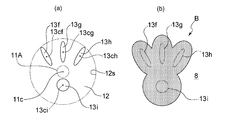
- FIG. 6 (a) shows another example of a foam discharge port formed at the bottom 12 of the foam diffusion space 3B.
- the foam discharge ports 13f to 13i having the shape and arrangement shown in FIG. 6 (a) at the bottom 12 of the foam diffusion space 3B of the foam discharge nozzle 3 of the foam discharge apparatus 1 of the embodiment described above, the foam discharge apparatus Each time the foam is quantitatively discharged toward the foam receiver 8 by 1, a foam shaped object B having a feather-like plan view shape of the battledore shown in FIG. 6B is formed on the foam receiver 8. be able to. Also in the example shown in FIG.
- the centroids 13cf to 13ci of the plurality of bubble discharge ports 13f to 13i do not overlap the centroid 11c of the supply port projection unit 11A and the supply port projection unit 11A itself, Further, all the foam discharge ports 13f to 13i do not overlap with the supply port projection unit 11A.
- FIG. 7A shows still another example of the foam discharge port formed at the bottom 12 of the foam diffusion space 3B.
- the foam discharge ports 13j, 13k, and 13r having the shape and arrangement shown in FIG. 7A at the bottom 12 of the foam diffusion space 3B of the foam discharge nozzle 3 of the foam discharge device 1 of the above-described embodiment,
- the foam shaped object B having a plan view shape imitating the face of an animal or a human shown in FIG. 8 can be formed.
- FIG. 8 shows still another example of the foam discharge port formed at the bottom 12 of the foam diffusion space 3B.
- the centroids 13cj and 13ck of the non-annular bubble discharge ports 13j and 13k do not overlap the centroid 11c of the supply port projection unit 11A and the supply port projection unit 11A itself.
- the annular bubble discharge port 13r is formed on the center of the bottom of the bubble diffusion space 3B and on the circumference of a circle centering on the centroid 11c of the supply port projection unit 11A.
- the centroid 13cr overlaps the centroid 11c of the supply port projection unit 11A and the supply port projection unit 11A.
- the bubble discharge port 13r itself does not overlap with the supply port projection unit 11A, and is formed in the vicinity of the periphery 12s of the bottom 12 of the bubble diffusion space 3B along the periphery 12s. There is a sufficient distance between the portion 11A.
- the centroid 13cr may coincide with the centroid 11c of the supply port projection unit 11A or may overlap the supply port projection unit 11A itself.
- the bubble discharge nozzle provided with the bubble discharge port of each shape and arrangement shown in 11 (a) is a preferred embodiment of the second invention.
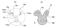
- FIG. 8A shows still another example of the foam discharge port formed at the bottom 12 of the foam diffusion space 3B.
- the foam discharge ports 13n, 13o, and 13p having the shape and arrangement shown in FIG. 8A at the bottom 12 of the foam diffusion space 3B of the foam discharge nozzle 3 of the foam discharge device 1 of the above-described embodiment,
- the foam shaped object B having a planar view shape imitating the face of a rabbit shown in FIG. Can be formed. Also in the example shown in FIG.
- the centroids 13cn, 13co, 13cp of the foam discharge ports 13n, 13o, 13p do not overlap the centroid 11c of the supply port projection unit 11A and the supply port projection unit 11A itself. Moreover, all the bubble discharge ports 13n, 13o, and 13p do not overlap with the supply port projection unit 11A.
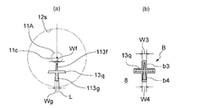
- FIG. 9A shows still another example of the foam discharge port formed at the bottom 12 of the foam diffusion space 3B.
- the bubble discharge port 13q having the shape and arrangement shown in FIG. 9A at the bottom 12 of the bubble diffusion space 3B of the bubble discharge nozzle 3 of the bubble discharge device 1 of the embodiment described above, the bubble discharge device 1
- the foam shaped article B having a cross-shaped plan view shown in FIG. 9B can be formed on the foam receiver 8.
- reference numeral 12s indicates the position of the periphery of the bottom 12 of the bubble diffusion space 3B.
- the foam discharge port 13q shown in FIG. 9A has a proximal portion 113f and a distal portion 113g having different distances from the centroid 11c of the supply port projection portion 11A. Then, the first part b3 of the foam model B is formed by the foam discharged from the proximal part 113f, and the second part b4 of the foam model B is formed by the foam discharged from the distal part 113g. Is done. Then, regarding the width in the direction orthogonal to the straight line L passing through the centroid 11c of the supply port projection part 11A, Wf / W3 which is the ratio of the width Wf of the proximal part 113f to the width W3 of the first part b3 is the second part.
- Wg / W4 is the ratio of the width Wg of the distal portion 113g to the width W4 of b4.
- the shape of the shaped object B is, for example, a triangle, a rectangle, a rhombus, a star, a cross, a card, a heart shape, a clover shape, a spade shape, a rabbit, a cat, an elephant, a bear, and other animals and game characters. And a shape imitating a part of a body such as a face, a shape imitating the contour of a vehicle such as a flower or plant, its fruit, an airplane, an automobile, or a yacht.
- the foam discharge device 1 of the present embodiment includes a second porous body 40 in the foam discharge port 13 of the foam discharge nozzle 3.
- a synthetic resin or metal mesh sheet, a sintered body of metal particles, a synthetic resin sponge-like molded body having a three-dimensional network structure, or the like can be used.
- the second porous body 40 is heat-sealed or superposed on the peripheral portion surrounding the bubble discharge port 13 on the upper end surface of the discharge port forming member 39.
- a method of joining with a sonic seal, an adhesive, or the like, or the second porous body 40 formed to have the same outer peripheral shape as the inner peripheral surface of the foam outlet 13 is fitted inside the foam outlet 13.
- Various methods can be employed such as By disposing the second porous body 40 in the foam discharge port 13, the foam-like foam supplied from the foam supply port 11 diffuses better in the horizontal direction in the foam diffusion space 3B. It is discharged at a speed averaged over the entire area of the bubble discharge port 13. As a result, a foamed article B having a clearer contour shape is formed on the surface of the bubble receiving body 8 such as a human hand.
- the second porous body 40 makes it possible to obtain finer foam-like foam, and it is easier to obtain a foam-shaped article B having a clear outline.
- the second porous body 40 may have the same or different pore diameter as the first porous body 33.
- the area of the second porous body 40 (the area of the upper surface or the lower surface) is preferably equal to or larger than the opening area on the bubble diffusion space 3B side or the external side of the bubble discharge port 13, and on the bubble diffusion space 3B side of the bubble discharge port 13. More preferably, it is larger than the opening area.
- the second porous body 40 is arranged on the bubble diffusion space 3B side of the discharge port forming member 39, the second porous body 40 is more preferably on the entire surface of the discharge port forming member 39 on the bubble diffusion space 3B side. .
- the upper surface 12a of the bottom 12 of the foam diffusion space 3B is formed from the upper surface of the discharge port forming member 39, and the second porous body 40 is on the upper surface of the discharge port forming member 39. It is arranged in a region including a portion overlapping with the bubble discharge port 13 and is preferably arranged over the entire region.
- the area of the second porous body 40 (the area of the upper surface or the lower surface) is preferably larger than the area of the outlet 32d of the gas-liquid mixing unit 32.
- the distance h (refer FIG. 2) from the 1st porous body 33 to the opening part by the side of the cavity of the bubble discharge port 13 from the point which the foamed modeling object B with a clear outline shape becomes easy to form is bubble diffusion.
- the equivalent circular diameter of the bubble diffusion space 3B calculated from the maximum value of the cross-sectional area of the space 3B is preferably 10% or more, more preferably 20% or more, and preferably 100% or less, more preferably 50% or less. is there.
- the distance h (see FIG. 2) is preferably smaller than the equivalent circle diameter of the bubble diffusion space 3B.
- the opening peripheral edge of the external opening protrudes in the bubble discharge direction T.
- the “external opening” is an opening that opens to the opposite side of the bubble diffusion space 3B. In the normal use state of the foam discharge device 1, the peripheral edge of the opening protrudes downward from the foam discharge nozzle 3.
- the horizontal diffusion promoting member 38 and the discharge port forming member 39 are disposed in the concave groove 38 h formed on the inner peripheral surface of the horizontal diffusion promoting member 38.
- the protruding rib 39h formed on the outer peripheral surface of the nozzle By fitting the protruding rib 39h formed on the outer peripheral surface of the nozzle, the boundary portion between them is connected without bonding, and by rotating the discharge port forming member 39 by hand, the bubble discharge port 13 is The position can be changed around the rotation axis extending in the discharge direction T. For example, by making it possible to change the direction of the foam discharge port 13 by such a method, the foam molded in a predetermined shape can be discharged in a desired direction on the foam receiver 8 such as a palm.
- the foam discharge device 1 When the direction of the foam discharge port 13 cannot be changed, the foam discharge device 1 is placed in the back of the washstand with the foam discharge nozzle 3 facing forward, and the foam discharge device 1 is ejected in the left side of the washstand.
- the direction of the foam shaped object B formed on the palm differs between the case where the nozzle 3 is directed to the right side and the case where the foam discharge device 1 is directed to the right side of the washstand and the foam discharge nozzle 3 is directed to the left side.
- the direction of the foam discharge port 13 can be changed and the direction of the foam discharge port 13 is changed according to the installation location of the foam discharge device 1, it depends on the installation location of the foam discharge device 1 on the palm. It is possible to form a foamed object B having the same orientation.
- the four It is also possible to adopt a method for enabling rotation between the mercer 34 and the horizontal diffusion promoting member 38, a method for attaching the foam discharge nozzle 3 to the foam discharge device 1 so that the entire foam discharge nozzle 3 can be rotated, and the like. it can.
- the discharge port forming member 39 is detachable from the horizontal diffusion promoting member 38, and the discharge port forming member 39 is In the removed state, it may be rotated so that the direction of the discharge port 39a is changed to a different direction and can be attached again.
- Making the discharge port forming member 39 detachable also has advantages such as improvement in maintainability and easy change of the shape of the foam model.
- the foam discharge nozzle 3 may be entirely made of synthetic resin, or may be made entirely or partially of a material other than synthetic resin such as metal or ceramic.
- synthetic resin for example, polyolefin such as polyethylene and polypropylene, polystyrene, polyethylene terephthalate (PET), polycarbonate, acrylic, polyamide, polyacetal, vinyl chloride and the like can be used.
- the foam discharged from the foam discharge nozzle 3 has a gas-liquid ratio (the former: latter) of air and liquid.
- the ratio is preferably 5: 1 to 100: 1, more preferably 10: 1 to 50: 1.
- Such bubbles with a gas-liquid ratio can be obtained by adjusting the speed and speed ratio of the gas and liquid sent to the foam discharge nozzle 3 and adjusting the viscosity of the liquid.
- the discharge amount (apparent volume) of one foam is preferably 5 cm 3 or more, more preferably 10 cm 3 or more, and preferably 100 cm 3 or less, more preferably 50 cm 3 or less.
- the amount of foam discharged is a normal volume, normal humidity, and normal pressure (20 ° C, 40RH%, 1 atm). It can be measured by putting the foam.
- the volume of the foam diffusion space 3B is preferably 0.05 to 2 times the foam discharge amount (apparent volume) at one time. 1 to 1 times is more preferable, and 0.2 to 0.8 times is more preferable. Further, the ratio of the volume of the bubble diffusion space 3B to the discharge amount (apparent volume) of one bubble is preferably less than 1 when the use frequency of the bubble discharge device 1 is low.
- the volume of the bubble diffusion space 3B is the volume of the space from the lower surface of the first porous body 33 to the position of the opening 39b on the bubble diffusion space 3B side of the bubble discharge port 13, for example, as shown in FIG.
- the second porous body 40 is arranged on the upper surface 39d of the discharge part forming member where the bubble discharge port 13 is opened, it is assumed that the second porous body 40 is not arranged in the bubble diffusion space 3B.
- the volume In addition, the cross-sectional area of the plane perpendicular to the bubble projecting direction from the lower surface of the first porous body 33 to the upper surface 39d of the discharge portion forming member where the bubble discharge port 13 opens is larger than the area of the outlet of the gas-liquid mixing portion.
- the volume of bubble diffusion space 3B is calculated
- the foam discharge nozzle 3 in the above-described embodiment is composed of a plurality of members, but two or more members are integrally molded, or a single member that is integrally molded is a combination of a plurality of members. It can also be replaced.
- the number of the foam discharge ports 13 formed at the bottom 12 of the foam diffusion space 3B may be single or plural. In a plurality of cases, the bubbles that have passed through the common bubble diffusion space 3 ⁇ / b> B are discharged from the plurality of bubble discharge ports 13.
- centroid 11c of the supply port projection unit 11A may not have the bubble diffusion space 3B of the bubble diffusion space 3B having a circular cross-sectional shape on the inner peripheral surface at the center of the bottom portion 12.
- the cross-sectional shape of the bubble diffusion space 3B may not be circular in plan view.
- the foam discharge device is configured to start supplying gas and liquid to the foam discharge nozzle 3 by detecting a signal from a push button or a contact type sensor instead of a non-contact type sensor.
- the foam discharge device may be used.
- the liquid supply mechanism sends gas into the storage part by an electric air pump or the like, and the liquid surface is pressed by the supplied gas, so that the pressed content liquid is arranged at one end in the content liquid. It may be sent to the foam discharge nozzle 3 through a plastic tube.
- the foam discharge device of the present invention may be a manual device, for example, a device in which air and liquid are sent to the bubble generation mechanism of the bubble discharge nozzle 3 by performing a pressing operation of the pump head. .
- the foam discharge apparatus 1 of embodiment mentioned above accommodates all the components in the housing
- Liquids include detergents such as liquid soap, hand sanitizers that can be made into a foam by adding an activator, hair cosmetics such as hair styling agents, fixing agents, hair restorers, and lotions. Skin cosmetics such as milky lotion and serum, shaving foam, dishwashing detergent and the like may also be used.
- the gas is usually air, but other gases such as nitrogen and helium may be used instead of air.
- the present invention further discloses the following additional notes (foam discharge nozzle, foam discharge device, etc.).
- a foam discharge nozzle of a foam discharge device A bubble diffusion space in which bubbles generated by mixing a liquid with a gas are supplied from a bubble supply port located on the upper side; A single or a plurality of foam outlets formed at the bottom of the foam diffusion space, In the bubble diffusion space, the area of the bottom is wider than the area of the bubble supply port, The bubble discharge nozzle, wherein the centroid of the bubble discharge port does not coincide with the centroid of the supply port projection unit that projects the bubble supply port onto the bottom in parallel with the central axis of the bubble diffusion space.
- ⁇ 2> The bubble discharge nozzle according to ⁇ 1>, wherein the area where the bubble discharge port overlaps the supply port projection unit is 0 to 30% of the area of the bubble discharge port.
- ⁇ 3> The bubble discharge nozzle according to ⁇ 1> or ⁇ 2>, wherein an area of a portion where the bubble discharge port and the supply port projection unit overlap is 0 to 10% of an area of the bubble discharge port.
- ⁇ 4> The bubble discharge nozzle according to any one of ⁇ 1> to ⁇ 3>, wherein a centroid of the bubble discharge port does not overlap with the supply port projection unit.
- ⁇ 5> The bubble discharge nozzle according to ⁇ 4>, wherein the bubble discharge port does not overlap the supply port projection unit.
- a foam discharge nozzle of a foam discharge device A bubble diffusion space in which bubbles generated by mixing a liquid with a gas are supplied from a bubble supply port located on the upper side; Having one or more foam outlets formed at the bottom of the foam diffusion space; In the bubble diffusion space, the area of the bottom is wider than the area of the bubble supply port, The bubble discharge port does not overlap with a supply port projection unit that projects the bubble supply port onto the bottom in parallel with the central axis of the bubble diffusion space, ⁇ 7>
- the bubble discharge nozzle according to any one of ⁇ 1> to ⁇ 6>, wherein the bubble discharge port includes a plurality of bubble discharge ports spaced apart from each other.
- the foam discharge port has a first discharge port that discharges bubbles that form the large area portion and a second discharge port that discharges bubbles that form the small area portion,
- the foam receiver it is possible to form a foam model having a large area part and a small area part having different sizes when viewed in plan
- the bubble discharge port it has a first discharge port for discharging bubbles forming the large area portion, and a second discharge port for discharging bubbles forming the small area portion
- Ga is the area of the large area portion
- Gb is the area of the small area portion
- Sa is the area of the first discharge port
- La is the centroid of the first discharge port and the centroid of the supply port projection unit.
- ⁇ is a real number not less than 0.1 and not more than 2.
- the main discharge part has a first discharge part that mainly discharges bubbles that form the large area part, and a second discharge part that mainly discharges bubbles that form the small area part.
- the foam discharge port has a foam discharge port having a proximal portion and a distal portion that are different in distance from the centroid of the supply port projection unit, and the foam discharged by the foam discharged from the proximal portion
- the first part is formed
- the second part of the foam model is formed by the foam discharged from the distal part,
- the ratio of the width of the proximal part to the width of the first part is greater than the ratio of the width of the distal part to the width of the second part.
- ⁇ 13> The foam discharge nozzle according to any one of ⁇ 1> to ⁇ 12>, wherein the foam discharge port includes a porous body.
- ⁇ 14> The bubble discharge nozzle according to any one of ⁇ 1> to ⁇ 13>, wherein the position of the bubble discharge port is changeable around a central axis of the bubble discharge nozzle.
- the bubble discharge device is an electric or pump type quantitative discharge device that supplies a fixed amount of bubbles to the bubble diffusion space and discharges a fixed amount of bubbles from the bubble discharge nozzle.
- the foam discharge nozzle according to any one of the above.
- the bubble discharge nozzle according to any one of ⁇ 1> to ⁇ 15>, wherein the bubble discharge nozzle includes a bubble generation mechanism.
- the said foam discharge nozzle is a foam discharge nozzle as described in said ⁇ 16> provided with the foam generation mechanism which has the gas-liquid mixing part which mixes a liquid and gas, and the porous body arrange
- the opening area on the bubble diffusion space side of the bubble discharge space is smaller than the maximum value of the cross-sectional area of the bubble diffusion space, and the bubble passing through the bubble diffusion space is discharged to the outside at the bottom of the bubble diffusion space.
- the top surface of the bottom of the bubble diffusion space is formed from the top surface of the discharge port forming member, and the porous body is disposed in a region including a portion overlapping the bubble discharge port on the top surface of the discharge port forming member.
- a foam ejection apparatus comprising the foam ejection nozzle according to any one of ⁇ 1> to ⁇ 20>.
- the foam discharge nozzle and the foam discharge apparatus of the present invention it is possible to stably form a foam shaped article in a desired shape.
Landscapes
- Health & Medical Sciences (AREA)
- Public Health (AREA)
- Nozzles (AREA)
- Containers And Packaging Bodies Having A Special Means To Remove Contents (AREA)
Priority Applications (4)
| Application Number | Priority Date | Filing Date | Title |
|---|---|---|---|
| HK18107715.9A HK1248177B (zh) | 2015-06-29 | 2016-06-16 | 泡沫吐出喷嘴和泡沫吐出装置 |
| US15/579,439 US10717094B2 (en) | 2015-06-29 | 2016-06-16 | Bubble discharging nozzle and bubble discharging device |
| EP16817739.2A EP3315206B1 (de) | 2015-06-29 | 2016-06-16 | Blasenentladedüse und blasenentladevorrichtung |
| CN201680038981.6A CN107847947B (zh) | 2015-06-29 | 2016-06-16 | 泡沫吐出喷嘴和泡沫吐出装置 |
Applications Claiming Priority (2)
| Application Number | Priority Date | Filing Date | Title |
|---|---|---|---|
| JP2015130420A JP6629533B2 (ja) | 2015-06-29 | 2015-06-29 | 泡吐出ノズル及び泡吐出装置 |
| JP2015-130420 | 2015-06-29 |
Publications (1)
| Publication Number | Publication Date |
|---|---|
| WO2017002630A1 true WO2017002630A1 (ja) | 2017-01-05 |
Family
ID=57608177
Family Applications (1)
| Application Number | Title | Priority Date | Filing Date |
|---|---|---|---|
| PCT/JP2016/067883 Ceased WO2017002630A1 (ja) | 2015-06-29 | 2016-06-16 | 泡吐出ノズル及び泡吐出装置 |
Country Status (5)
| Country | Link |
|---|---|
| US (1) | US10717094B2 (de) |
| EP (1) | EP3315206B1 (de) |
| JP (1) | JP6629533B2 (de) |
| CN (1) | CN107847947B (de) |
| WO (1) | WO2017002630A1 (de) |
Cited By (1)
| Publication number | Priority date | Publication date | Assignee | Title |
|---|---|---|---|---|
| EP4378859A3 (de) * | 2017-11-17 | 2024-08-07 | FrieslandCampina Nederland B.V. | Vorrichtung und verfahren zur ausgabe und aufschäumung eines produkts |
Families Citing this family (12)
| Publication number | Priority date | Publication date | Assignee | Title |
|---|---|---|---|---|
| US10478834B2 (en) | 2014-11-28 | 2019-11-19 | Kao Corporation | Foam dispensing container |
| US10349785B2 (en) | 2015-04-28 | 2019-07-16 | Kao Corporation | Foam discharge device |
| JP6622246B2 (ja) * | 2016-04-15 | 2019-12-18 | 花王株式会社 | 泡吐出装置 |
| US11304571B2 (en) | 2016-04-15 | 2022-04-19 | Kao Corporation | Foam discharge device |
| JP6985820B2 (ja) * | 2017-05-26 | 2021-12-22 | 花王株式会社 | 泡プロジェクションマッピング方法 |
| EP3513880B1 (de) | 2018-01-23 | 2021-08-25 | The Procter & Gamble Company | Abgabevorrichtung, die für schäumende produkte geeignet ist |
| US11267644B2 (en) * | 2018-11-08 | 2022-03-08 | The Procter And Gamble Company | Aerosol foam dispenser and methods for delivering a textured foam product |
| US11111909B2 (en) * | 2019-06-26 | 2021-09-07 | Faner Aroma Product Co., Ltd. | Liquid foam delivery device |
| MX2022011288A (es) * | 2020-03-11 | 2022-10-07 | Musashi Eng Inc | Metodo de formacion de pelicula liquida plana y aparato de formacion de pelicula liquida plana. |
| ES2992119T3 (es) * | 2020-03-18 | 2024-12-09 | Hans Georg Hagleitner | Procedimiento para calibrar la cantidad de dispensación de un dispensador |
| CN111938478A (zh) * | 2020-07-12 | 2020-11-17 | 意杉(杭州)科技有限公司 | 一种洗手给皂器 |
| CN115299804A (zh) * | 2022-08-08 | 2022-11-08 | 珠海格力电器股份有限公司 | 喷头结构和皂液机装置 |
Citations (7)
| Publication number | Priority date | Publication date | Assignee | Title |
|---|---|---|---|---|
| JP2003111810A (ja) * | 2001-10-04 | 2003-04-15 | Matsushita Electric Ind Co Ltd | 微細気泡発生装置のノズル |
| JP2006159092A (ja) * | 2004-12-07 | 2006-06-22 | Kurashiki System Design:Kk | 混合ノズルとこれを用いた手洗装置 |
| JP2006346611A (ja) * | 2005-06-17 | 2006-12-28 | Horai Sangyo Kk | 洗浄液噴射装置 |
| JP3159292U (ja) * | 2010-02-25 | 2010-05-13 | 美通興業有限公司 | 泡沫発生装置 |
| JP2011031889A (ja) * | 2009-07-29 | 2011-02-17 | Mitani Valve Co Ltd | 容器内容物の泡生成用アタッチメント,容器内容物の泡生成用アタッチメントを備えたポンプ式製品およびエアゾール式製品 |
| JP3169573U (ja) * | 2011-05-26 | 2011-08-04 | 武巧 周 | バブル発生装置 |
| JP2014000569A (ja) * | 2012-06-19 | 2014-01-09 | General Electric Co <Ge> | 少なくとも1つのウォータカーテンを生成する装置のためのモジュールおよび対応する装置 |
Family Cites Families (13)
| Publication number | Priority date | Publication date | Assignee | Title |
|---|---|---|---|---|
| US6848597B2 (en) * | 2001-04-18 | 2005-02-01 | James A. Vlodek | Methods and apparatus for extruding foam through orifices |
| US7543722B2 (en) * | 2005-09-06 | 2009-06-09 | Joseph S. Kanfer | Foam soap generator and pump |
| US7819289B2 (en) * | 2006-04-14 | 2010-10-26 | Joseph S Kanfer | Foam soap generator |
| JP5412106B2 (ja) | 2008-12-25 | 2014-02-12 | ライオン株式会社 | 泡吐出用アダプタ及び泡ポンプ付き容器 |
| JP2010269233A (ja) | 2009-05-20 | 2010-12-02 | Lion Corp | 泡吐出用アダプタ及び泡吐出装置 |
| EP2505266B1 (de) * | 2009-11-25 | 2020-03-18 | Daizo Corporation | Sprühdüse und aerosolprodukt |
| EP2572795A4 (de) * | 2010-05-06 | 2013-10-16 | Mitani Valve Co Ltd | Anbauelement für aufschäumbehälterinhalt und pumpenprodukt und aerosolprodukt, die mit einem anbauelement für aufschäumbehälterinhalte ausgestattet sind |
| FR2983079B1 (fr) | 2011-11-30 | 2017-04-28 | Ge Energy Products France Snc | Module pour dispositif de generation d'au moins un rideau d'eau, et dispositif correspondant |
| JP5873374B2 (ja) | 2012-04-02 | 2016-03-01 | ホシデン株式会社 | 溶液供給装置 |
| US8814005B2 (en) * | 2012-04-27 | 2014-08-26 | Pibed Limited | Foam dispenser |
| GB201321484D0 (en) | 2013-12-05 | 2014-01-22 | Kokomo Ltd | Foam formulation and aerosol can assembly |
| JP6215263B2 (ja) | 2014-11-28 | 2017-10-18 | 花王株式会社 | 泡吐出容器 |
| US10349785B2 (en) | 2015-04-28 | 2019-07-16 | Kao Corporation | Foam discharge device |
-
2015
- 2015-06-29 JP JP2015130420A patent/JP6629533B2/ja active Active
-
2016
- 2016-06-16 US US15/579,439 patent/US10717094B2/en active Active
- 2016-06-16 CN CN201680038981.6A patent/CN107847947B/zh active Active
- 2016-06-16 WO PCT/JP2016/067883 patent/WO2017002630A1/ja not_active Ceased
- 2016-06-16 EP EP16817739.2A patent/EP3315206B1/de active Active
Patent Citations (7)
| Publication number | Priority date | Publication date | Assignee | Title |
|---|---|---|---|---|
| JP2003111810A (ja) * | 2001-10-04 | 2003-04-15 | Matsushita Electric Ind Co Ltd | 微細気泡発生装置のノズル |
| JP2006159092A (ja) * | 2004-12-07 | 2006-06-22 | Kurashiki System Design:Kk | 混合ノズルとこれを用いた手洗装置 |
| JP2006346611A (ja) * | 2005-06-17 | 2006-12-28 | Horai Sangyo Kk | 洗浄液噴射装置 |
| JP2011031889A (ja) * | 2009-07-29 | 2011-02-17 | Mitani Valve Co Ltd | 容器内容物の泡生成用アタッチメント,容器内容物の泡生成用アタッチメントを備えたポンプ式製品およびエアゾール式製品 |
| JP3159292U (ja) * | 2010-02-25 | 2010-05-13 | 美通興業有限公司 | 泡沫発生装置 |
| JP3169573U (ja) * | 2011-05-26 | 2011-08-04 | 武巧 周 | バブル発生装置 |
| JP2014000569A (ja) * | 2012-06-19 | 2014-01-09 | General Electric Co <Ge> | 少なくとも1つのウォータカーテンを生成する装置のためのモジュールおよび対応する装置 |
Non-Patent Citations (1)
| Title |
|---|
| See also references of EP3315206A4 * |
Cited By (2)
| Publication number | Priority date | Publication date | Assignee | Title |
|---|---|---|---|---|
| EP4378859A3 (de) * | 2017-11-17 | 2024-08-07 | FrieslandCampina Nederland B.V. | Vorrichtung und verfahren zur ausgabe und aufschäumung eines produkts |
| US12090505B2 (en) | 2017-11-17 | 2024-09-17 | Frieslandcampina Nederland B.V. | Apparatus and methods for dispensing and foaming of a product |
Also Published As
| Publication number | Publication date |
|---|---|
| EP3315206B1 (de) | 2023-07-19 |
| US10717094B2 (en) | 2020-07-21 |
| CN107847947B (zh) | 2021-02-02 |
| JP6629533B2 (ja) | 2020-01-15 |
| EP3315206A1 (de) | 2018-05-02 |
| CN107847947A (zh) | 2018-03-27 |
| US20180141064A1 (en) | 2018-05-24 |
| EP3315206A4 (de) | 2019-01-09 |
| JP2017012972A (ja) | 2017-01-19 |
| HK1248177A1 (zh) | 2018-10-12 |
Similar Documents
| Publication | Publication Date | Title |
|---|---|---|
| JP6629533B2 (ja) | 泡吐出ノズル及び泡吐出装置 | |
| JP6085711B2 (ja) | 泡吐出装置 | |
| JP6587662B2 (ja) | 泡吐出容器 | |
| JP6359289B2 (ja) | 泡吐出容器 | |
| JP2019172313A (ja) | 液体吐出容器 | |
| JP2017007706A (ja) | 泡吐出容器 | |
| JP2017193374A (ja) | 泡吐出装置 | |
| JP6486222B2 (ja) | ディスペンサー | |
| WO2017179684A1 (ja) | 泡吐出装置 | |
| JP2020015539A (ja) | 液体吐出容器 | |
| JP2016120940A (ja) | 泡吐出容器 | |
| JP6242368B2 (ja) | 泡吐出容器 | |
| WO2016084955A1 (ja) | 泡吐出容器 | |
| HK1248177B (zh) | 泡沫吐出喷嘴和泡沫吐出装置 | |
| HK1243033B (zh) | 泡沫吐出装置 | |
| JP7455487B2 (ja) | フォーマーディスペンサー及びフォーマーディスペンサー付き容器 | |
| JP6781729B2 (ja) | 泡吐出装置 | |
| JP6539323B2 (ja) | 泡吐出容器 | |
| JP6420615B2 (ja) | 吐出容器及びディスペンサー | |
| JP2018075557A (ja) | 泡吐出装置 |
Legal Events
| Date | Code | Title | Description |
|---|---|---|---|
| 121 | Ep: the epo has been informed by wipo that ep was designated in this application |
Ref document number: 16817739 Country of ref document: EP Kind code of ref document: A1 |
|
| WWE | Wipo information: entry into national phase |
Ref document number: 15579439 Country of ref document: US |
|
| NENP | Non-entry into the national phase |
Ref country code: DE |