WO2017005307A1 - Appareil de lavage de bouteilles destiné à être utilisé sur le panier de lave-vaisselle - Google Patents
Appareil de lavage de bouteilles destiné à être utilisé sur le panier de lave-vaisselle Download PDFInfo
- Publication number
- WO2017005307A1 WO2017005307A1 PCT/EP2015/065496 EP2015065496W WO2017005307A1 WO 2017005307 A1 WO2017005307 A1 WO 2017005307A1 EP 2015065496 W EP2015065496 W EP 2015065496W WO 2017005307 A1 WO2017005307 A1 WO 2017005307A1
- Authority
- WO
- WIPO (PCT)
- Prior art keywords
- bottle washing
- washing apparatus
- spray unit
- spray
- docking port
- Prior art date
- Legal status (The legal status is an assumption and is not a legal conclusion. Google has not performed a legal analysis and makes no representation as to the accuracy of the status listed.)
- Ceased
Links
Images






Classifications
-
- A—HUMAN NECESSITIES
- A47—FURNITURE; DOMESTIC ARTICLES OR APPLIANCES; COFFEE MILLS; SPICE MILLS; SUCTION CLEANERS IN GENERAL
- A47L—DOMESTIC WASHING OR CLEANING; SUCTION CLEANERS IN GENERAL
- A47L15/00—Washing or rinsing machines for crockery or tableware
- A47L15/42—Details
- A47L15/50—Racks ; Baskets
- A47L15/505—Inserts, e.g. for holding baby bottles, stemware or cups
-
- A—HUMAN NECESSITIES
- A47—FURNITURE; DOMESTIC ARTICLES OR APPLIANCES; COFFEE MILLS; SPICE MILLS; SUCTION CLEANERS IN GENERAL
- A47L—DOMESTIC WASHING OR CLEANING; SUCTION CLEANERS IN GENERAL
- A47L15/00—Washing or rinsing machines for crockery or tableware
- A47L15/42—Details
- A47L15/4278—Nozzles
-
- A—HUMAN NECESSITIES
- A47—FURNITURE; DOMESTIC ARTICLES OR APPLIANCES; COFFEE MILLS; SPICE MILLS; SUCTION CLEANERS IN GENERAL
- A47L—DOMESTIC WASHING OR CLEANING; SUCTION CLEANERS IN GENERAL
- A47L15/00—Washing or rinsing machines for crockery or tableware
- A47L15/42—Details
- A47L15/50—Racks ; Baskets
- A47L15/508—Hydraulic connections for racks
Definitions
- the present invention relates to the treatment of hollow articles, in particular to hollow articles with relatively narrow openings such as bottles, feeding bottles and jars in a domestic dishwasher.
- a domestic dishwasher generally includes two article racks which are extendably disposed into the washing tub one above the other.
- the article racks are commonly made from a wire mesh which holds the kitchenware to be cleaned and dried.
- the user can load up the article racks with various kitchenware such as pots, pans, trays, dishes, bowls, cups, bottles and jars.
- kitchenware such as cutlery is generally placed into the cutlery basket which has a relatively finer mesh.
- the articles which are loaded into the upper rack and the lower rack are generally washed and rinsed by means of two rotating spray arms that upwardly spray the washing/rinsing liquid towards the racks respectively.
- the dishwasher includes a hydraulic circuit for circulating the washing/rinsing liquid via the rotating spray arms.
- the hydraulic circuit is generally controlled by the control unit in accordance with user-selectable washing programs.
- the pressurized washing/rinsing liquid hits the articles, removes the dirt, marks or stain from the articles and drains down together with the dissolved dirt into the sump which is located on the bottom of the tub.
- a common problem with the prior art domestic dishwashers is that the hollow articles, in particular the hollow articles with relatively narrow openings such as drinking containers, bottles, feeding bottles and jars may not suffiently receive the washing/rinsing liquid and remain dirty after the completion of the selected washing program. In such incidents, the user needs to wash the unclean articles again. In general, the poor washing results decrease the user satisfaction.
- WO 2010133674 (A1) discloses a prior art domestic dishwasher.
- An objective of the present invention is to provide a bottle washing apparatus for use in a dishwasher which solves the aforementioned problems of the prior art in a cost effective way and which enables an improved cleaning performance of the hollow articles.
- the dishwasher of the present invention comprises a first docking port which opens into the tub and exclusively docks with or undocks from the bottle washing apparatus and exclusively supplies the same, in the docked state, with the washing/rinsing liquid.
- the hydraulic circuit of the dishwasher is further configured and controlled so as to circulate the washing/rinsing liquid via the firs docking port to the bottle washing apparatus.
- the inner bottom of at least one of the extendable article racks is configured for releasable installation of the bottle washing apparatus.
- the bottle washing apparatus of the present invention comprises a separate non-rotating spray unit which can be detachably attached onto the inner bottom of at least one of the extendable article racks.
- the spray unit directly docks with or undocks from the first docking port when the respective rack is pushed in or pulled out of the tub respectively.
- the spray unit washes/rinses a hollow article that is to be placed thereover upside down onto the respective rack.
- a major advantageous effect of the present invention is that the interior of the hollow articles can be intensively cleaned by the spray unit. Thereby, the risk of having poor washing results has been eliminated or reduced as much as possible.
- Another major advantageous effect of the present invention is that the user is enabled to easily detach the spray unit from the inter bottom of the article rack when it is not needed. Alternatively, the user may detach the spray unit for maintenance or upgrade.
- Another major advantageous effect of the present invention is that the circulation of the washing/rinsing liquid through the spray unit can be flexibly controlled in accordance with the actual user requirements and thus the energy efficiency and the water use efficiency of the dishwasher can be further improved.
- the spray unit is detachably attachable to the lower article rack.
- This embodiment is particularly advantageous as the relatively large gap above the lower rack allows the tall hollow articles to be easily placed over the spray unit. Thereby the consumer satisfaction can be increased.
- the spray unit is detachably attachable to the upper rack.
- the spray unit is detachably attachable onto the rearmost area of the lower article rack.
- This embodiment is particularly advantageous as the hollow articles can be orderly and securely placed along the rear wall of the lower article rack over the spray unit. Thereby, the space inside the lower rack can be more efficiently utilized.
- the first docking port includes a safety valve which becomes closed when the spray unit is undocked or detached.
- This embodiment is particularly advantageous as the hydraulic circuit cannot circulate the water through the first docking port when the user has detached the spray unit.
- the spray unit may be detachably attached to the wires of the rack by various types of releasable connections. For instance, a snap connection, an interlocking connection, a clamping connection or a screw connection may be used.
- the spray unit is detachably attached to the rack by one or more resilient claws. This embodiment is particularly advantageous as the claws are easy to handle.
- the resilient claws releasably catch the wires when the spray unit is pressed downwardly onto the inner bottom of the rack. This embodiment is particularly advantageous as the user can perform the attachment/detachment easily and quickly from above.
- the spray unit has primary nozzles for washing/rinsing the interior of the hollow articles respectively.
- This embodiment is particularly advantageous as the user can allocate the hollow articles to the primary nozzles respectively.
- the primary nozzles form an array so as to effectively match the respective hollow articles which are aligned upside down over the spray unit.
- the primary nozzles spray the liquid upwards and may have various spray patterns.
- the primary nozzles may be static or alternatively rotate about their own axis.
- the spray unit has also secondary nozzles for washing/rinsing the neighboring dishes which are placed between the tines of the rack.
- This embodiment is particularly advantageous as the washing/rinsing performance of the dishwasher can be further improved.
- the secondary nozzles also form an array so to effectively match the dishes which are aligned close to the spray unit.
- the secondary nozzles spray slantwise and may have various spray patterns.
- the primary nozzles may be static or alternatively rotate about their own axis.
- the spray unit has a size which occupies a relatively small space on the inner bottom of the rack. This embodiment is particularly advantageous as the spray unit does not inhibit loading of the rack with the usual articles even when the user does not intend to use the bottle washing apparatus and leaves it attached to the rack.
- the spray unit is a single piece. This embodiment is particularly advantageous as the number of parts can be decreased and the productions cost can be reduced.
- the spray unit may be molded from a durable plastic material.
- the spray unit may be manufactured from a light metal or metal alloy.
- the washing/rinsing liquid can be individually circulated via the first docking port to the bottle washing apparatus.
- This embodiment is particularly advantageous as the hollow articles can be intensively washed and rinsed with a comparatively high flowrate.
- the bottle washing apparatus may be taken into operation i.e., supplied with the washing/rinsing liquid at a moment when the rotating spray arms are standing idle, i.e., not supplied with the washing/rinsing liquid.
- the water-use efficiency, the energy efficiency and also the cleaning performance of the dishwasher can be improved.
- the noise emission of the dishwasher can be reduced.
- a multiway valve in particular a three-way valve is used in the hydraulic circuit in order to selectively and individually circulate the washing/rinsing liquid by means of a circulation pump via three separate lines to the lower rotating spray arm, to the upper rotating spray arm and to the spray unit of the bottle washing apparatus respectively.
- a ceiling-mounted spray means of the cutlery tray is also joined to the separate line of the the upper rotating spray arm so as to be operated in common.
- the multiway valve is also used to feed additional separate lines which for instance lead to the microfilter cleaning unit, a reservoir unit and an intensive cleaning zone which is located on the bottom of the tub respectively. Thereby, the dishwasher can be more flexibly controlled.
- the user is allowed to select via the control panel the bottle washing function.
- the control unit causes the hydraulic circuit to circulate the washing/rinsing liquid to the bottle washing apparatus only if the function has been selected by the user.
- This embodiment is particularly advantageous as the bottle washing apparatus is operated only when needed and thus the dishwasher can save energy and water.
- the bottle washing function is combinable with the other user-selectable washing programs.
- the hollow articles are secured in place by a wire retainer which can be releasably or retractably attached to the rack.
- a wire retainer which can be releasably or retractably attached to the rack.
- Figure 1 – is a schematic perspective view of a bottle washing apparatus according to an embodiment of the present invention.
- Figure 2 – is a schematic top view of the bottle washing apparatus of Fig. 1;
- Figure 3 – is a schematic front view of the bottle washing apparatus of Fig. 1;
- Figure 4 – is a schematic enlarged top view of the detail A of Fig. 2;
- Figure 5 – is a schematic enlarged partial perspective view of the bottle washing apparatus of Fig. 1;
- Figure 6 – is a schematic enlarged perspective view of the detail B of Fig. 5;
- Figure 7 – is a schematic enlarged partial perspective rear view of the bottle washing apparatus of Fig. 1;
- Figure 8 – is a schematic enlarged partial perspective side view of the bottle washing apparatus of Fig. 1;
- Figure 9 – is a schematic perspective view of a dishwasher which has the bottle washing apparatus according to an embodiment of the present invention.
- Figure 10 – is a schematic partial perspective inner view of the dishwasher of Fig. 9;
- Figure 11 – is another schematic partial perspective inner view of the dishwasher of Fig.9;
- Figure 12 – is a schematic enlarged partial perspective inner view of the dishwasher of Fig.9;
- Figure 13 – is a schematic partial top inner view of the dishwasher of Fig. 9;
- Figure 14 – is a another schematic partial perspective view of the dishwasher of Fig. 9, when the bottle washing apparatus has been docked with the first docking port;
- Figure 15 – is a schematic exploded partial perspective view of the first docking port of Fig. 14;
- Figure 16 – is a schematic partial perspective front view of the first docking port of Fig. 14, when the hinged flap is closed;
- Figure 17 – is a schematic partial perspective front view of the first docking port of Fig.14, when the hinged flap is open;
- Figure 18 – is a schematic partial perspective rear view of the first docking port of Fig.14, when the hinged flap is closed;
- Figure 19 – is a schematic partial perspective rear view of the first docking port of Fig.14, when the hinged flap is open;
- Figure 20 – is a schematic partial top inner view of the dishwasher of Fig. 9, when the bottle washing apparatus has been docked with the first docking port;
- Figure 21 – is a schematic sectional view of the bottle washing apparatus and the first docking port, taken along the line C-C of Fig. 20;
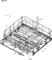
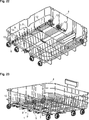
- Figure 22 – is a schematic perspective view of the lower article rack of the dishwasher of Fig. 9, wherein the bottle washing apparatus is detachably attached to the rearmost area on the inner bottom of the lower article rack;
- Figure 23 – is another schematic perspective view of the lower article rack and the bottle washing apparatus of Fig. 22;
- Figure 24 – is a schematic enlarged partial perspective view of the lower article rack and the bottle washing apparatus of Fig. 22;
- Figure 25 – is a schematic enlarged partial perspective view of the lower article rack and the bottle washing apparatus of Fig. 23;
- Figure 26 — is a schematic enlarged perspective view of the detail D of Fig. 25;
- Figure 27 — is a schematic enlarged perspective view of the detail E of Fig. 25;
- Figure 28 – is a schematic rear view of the lower article rack and the bottle washing apparatus of Fig. 22;
- Figure 29 – is a schematic enlarged perspective view of the detail F of Fig. 28.
- the bottle washing apparatus (1) of the present invention is suitable for use in a dishwasher (2).
- the dishwasher (2) comprises a tub (3), a sump (15) which is located on the bottom of the tub (3), one or more extendable article racks (4) which are disposed into the tub (3) one above the other, one or more rotating spray arms (16) for spraying the washing/rinsing liquid towards the respective article racks (4), a hydraulic circuit (6) for circulating the liquid via the rotating spray arms (16) and a control unit (not shown) for controlling the hydraulic circuit (6).
- the control unit comprises one or more user selectable washing programs.
- the dishwasher (2) of the present invention further comprises a first docking port (5) which is configured to open into tub (3) and to exclusively dock with or undock from the bottle washing apparatus (1) and to exclusively supply the bottle washing apparatus (1), in the docked state, with the washing/rinsing liquid.
- the hydraulic circuit (6) is further configured to circulate the washing/rinsing liquid via the first docking port (5).
- the inner bottom of at least one of the racks (4) is configured for releasable installation of the bottle washing apparatus (1).
- the bottle washing apparatus (1) of the present invention comprises: a separate non-rotating spray unit (7) which is configured for detachable attachment onto the inner bottom of at least one of the racks (4), to directly dock with or undock from the first docking port (5) when the respective rack (4) is pushed in or pulled out of the tub (3) respectively and to wash/rinse a hollow article (not shown) that is to be placed thereover upside down onto the respective rack (4).
- the spray unit (7) is configured for detachable attachment onto the inner bottom of the lower article rack (4).
- the spray unit (7) is further configured for detachable attachment exclusively onto the rearmost area on the inner bottom of the lower article rack (4) and to wash/rinse the hollow articles that are to be placed thereover upside down onto the rearmost area of the lower article rack (4).
- the first docking port (5) includes a safety valve (8) which is configured to cooperate with the spray unit (7) and to open when the spray unit (7) is docked and to close when the spray unit (7) is undocked.
- the safety valve (8) includes a hinged flap (8) which is pushed inwardly by a protrusion (21) of the spray unit (7) in the docked state.
- the protrusion (21) is disposed onto the inlet (22) of the spray unit (7).
- the racks comprise wires (9).
- the spray unit (7) comprises one or more resilient claws (10) which are configured to releasably catch the counterpart wires (9).
- the resilient claws (10) are disposed onto the bottom of the spray unit (7) and extend downwardly so as to releasably catch the counterpart wires (9) when the spray unit (7) is pressed downwardly onto the inner bottom of the respective rack (4).
- the spray unit (7) comprises one or more primary nozzles (11) which are configured to spray the washing/rinsing fluid upwardly and directly into the hollow article.
- the primary nozzles (11) are arrayed onto the body of the spray unit (7).
- the primary nozzles (11) are fluidly connected with the inlet (22) through a duct (23) which is formed into the body of the spray unit (7).
- the article racks (4) each comprises one or more sets of tines (12) for respectively supporting dishes.
- the spray unit (7) comprises one or more secondary nozzles (13) which are configured to spray the washing/rinsing fluid slantwise and directly towards the dishes to be placed onto the respective rack (4) between the tines (12).
- the secondary nozzles (13) are also arrayed onto the body of the spray unit (7).
- the secondary nozzles (11) are fluidly connected with the inlet (22) through the duct (23).
- the spray unit (7) has an elongated shape which extends along the entire width of the respective rack (4) and a relatively low height such that it does not interfere, in the attached sate, with the dishes to be placed onto the respective rack (4) between the tines (12).
- the duct (23) of the spray unit (7) has a rectangular cross section whereas the inlet (22) has a cylindrical cross section.
- the spray unit (7) has one or more barrier-like projections (14) configured to inhibit dislocation of the hollow articles that are to be placed thereover upside down onto the respective rack (4).
- the spray unit (7) including the claws (10), the primary nozzles (11), the secondary nozzles (13), the projections (14), the inlet (22) and the duct (23) are integrally moulded as a single piece.
- the spray unit (7) has static primary and secondary nozzles (11, 13).
- the hydraulic circuit (6) has an individual first line which is configured to allow individual circulation of the washing/rinsing liquid via the first docking port (5) to the bottle washing apparatus (1).
- the hydraulic circuit (6) comprises a multiway valve unit (not shown) which includes: an inlet port (not shown) which is configured to receive the liquid from the sump (15), a first outlet port (not shown) which is configured to allow individual circulation of the liquid via the first individual line (17) and the first docking port (5) to the bottle washing apparatus (1), a second outlet port (not shown) which is configured to allow individual circulation of the liquid via a second individual line (18) and a second docking port (19) to the upper rotating spray arm, a third outlet port (not shown) which is configured to allow individual circulation of the liquid via a third individual line (20) to the lower rotating spray arm (16).
- a multiway valve unit (not shown) which includes: an inlet port (not shown) which is configured to receive the liquid from the sump (15), a first outlet port (not shown) which is configured to allow individual circulation of the liquid via the first individual line (17) and the first docking port (5) to the bottle washing apparatus (1), a second outlet port (not shown) which is configured to allow individual circulation of the
- control unit further comprises a user selectable bottle washing function.
- control unit is further programmed to circulate the washing/rinsing liquid via the first docking port (5) in combination with a selected washing program if the bottle washing function has also been selected by the user.
- the dishwasher (2) further comprises a wire retainer (not shown) which is configured for releasable or retractable attachment to the respective rack (4) and to secure the hollow articles including bottles and stemware that are to be placed over the spray unit (7) upside down onto the respective rack (4).
- a wire retainer (not shown) which is configured for releasable or retractable attachment to the respective rack (4) and to secure the hollow articles including bottles and stemware that are to be placed over the spray unit (7) upside down onto the respective rack (4).
- a major advantageous effect of the present invention is that the interior of the hollow articles can be intensively cleaned by the spray unit (7). Thereby, the risk of having poor washing results has been eliminated or reduced as much as possible.
- Another major advantageous effect of the present invention is that the user is enabled to easily detach the spray unit (7) from the inner bottom of article rack (4) when it is not needed. Alternatively, the user may detach the spray unit (7) for maintenance or upgrade.
- Another major advantageous effect of the present invention is that the circulation of the washing/rinsing liquid through the spray unit (7) can be flexibly controlled and thus the energy efficiency and the water use efficiency of the dishwasher (2) can be further improved.
- Other advantageous effects of the present invention can be taken from the aforementioned particular embodiments.
Landscapes
- Washing And Drying Of Tableware (AREA)
Abstract
La présente invention concerne un dispositif de lavage de bouteilles (1) destiné à être utilisé dans un lave-vaisselle (2). Le lave-vaisselle (2) de la présente invention comprend un premier port d'accueil (5) qui s'ouvre à l'intérieur d'une cuve (3) et qui se connecte à l'appareil ou se déconnecte de ce dernier (1) et fournit exclusivement à l'appareil (1), dans l'état connecté, le liquide de lavage/rinçage. Le circuit hydraulique (6) fait circuler le liquide par l'intermédiaire du premier port d'accueil (5).
Priority Applications (4)
| Application Number | Priority Date | Filing Date | Title |
|---|---|---|---|
| EP15752929.8A EP3319499B1 (fr) | 2015-07-07 | 2015-07-07 | Appareil de lavage de bouteilles destiné à être utilisé sur le panier de lave-vaisselle |
| PL15752929T PL3319499T3 (pl) | 2015-07-07 | 2015-07-07 | Urządzenie do mycia butelek do stosowania na koszu zmywarki do naczyń |
| PCT/EP2015/065496 WO2017005307A1 (fr) | 2015-07-07 | 2015-07-07 | Appareil de lavage de bouteilles destiné à être utilisé sur le panier de lave-vaisselle |
| US15/741,957 US20180192851A1 (en) | 2015-07-07 | 2015-07-07 | Bottle washing apparatus for use on the dishwasher rack |
Applications Claiming Priority (1)
| Application Number | Priority Date | Filing Date | Title |
|---|---|---|---|
| PCT/EP2015/065496 WO2017005307A1 (fr) | 2015-07-07 | 2015-07-07 | Appareil de lavage de bouteilles destiné à être utilisé sur le panier de lave-vaisselle |
Publications (1)
| Publication Number | Publication Date |
|---|---|
| WO2017005307A1 true WO2017005307A1 (fr) | 2017-01-12 |
Family
ID=53887071
Family Applications (1)
| Application Number | Title | Priority Date | Filing Date |
|---|---|---|---|
| PCT/EP2015/065496 Ceased WO2017005307A1 (fr) | 2015-07-07 | 2015-07-07 | Appareil de lavage de bouteilles destiné à être utilisé sur le panier de lave-vaisselle |
Country Status (4)
| Country | Link |
|---|---|
| US (1) | US20180192851A1 (fr) |
| EP (1) | EP3319499B1 (fr) |
| PL (1) | PL3319499T3 (fr) |
| WO (1) | WO2017005307A1 (fr) |
Families Citing this family (27)
| Publication number | Priority date | Publication date | Assignee | Title |
|---|---|---|---|---|
| US10524634B2 (en) | 2017-09-29 | 2020-01-07 | Midea Group Co., Ltd. | Dishwasher with combined liquid and air sprayers |
| US12290225B2 (en) | 2017-09-29 | 2025-05-06 | Midea Group Co., Ltd. | Dishwasher with walking tubular spray element |
| US10531781B2 (en) | 2017-09-29 | 2020-01-14 | Midea Group Co., Ltd. | Dishwasher with discretely directable tubular spray elements |
| US10631708B2 (en) | 2018-09-14 | 2020-04-28 | Midea Group Co., Ltd. | Dishwasher with docking arrangement for elevation-adjustable rack |
| US11071440B2 (en) | 2018-09-14 | 2021-07-27 | Midea Group Co., Ltd. | Dishwasher with rack-mounted conduit return mechanism |
| US11000176B2 (en) | 2018-09-14 | 2021-05-11 | Midea Group Co., Ltd. | Dishwasher with rotatable diverter valve |
| US10765291B2 (en) | 2018-09-14 | 2020-09-08 | Midea Group Co., Ltd. | Dishwasher with check valve in rotatable docking port |
| US11045066B2 (en) | 2019-03-11 | 2021-06-29 | Midea Group Co., Ltd. | Dishwasher with keyed coupling to rack-mounted conduit |
| US11026559B2 (en) | 2019-09-30 | 2021-06-08 | Midea Group Co., Ltd. | Dishwasher with image-based fluid condition sensing |
| US11399690B2 (en) | 2019-09-30 | 2022-08-02 | Midea Group Co., Ltd. | Dishwasher with cam-based position sensor |
| US11259681B2 (en) | 2019-09-30 | 2022-03-01 | Midea Group Co., Ltd | Dishwasher with image-based diagnostics |
| US11484183B2 (en) | 2019-09-30 | 2022-11-01 | Midea Group Co., Ltd. | Dishwasher with image-based object sensing |
| US11464389B2 (en) | 2019-09-30 | 2022-10-11 | Midea Group Co., Ltd. | Dishwasher with image-based detergent sensing |
| US11191416B2 (en) | 2019-09-30 | 2021-12-07 | Midea Group Co., Ltd. | Dishwasher with image-based position sensor |
| US11202550B2 (en) | 2019-11-20 | 2021-12-21 | Midea Group Co., Ltd. | Dishwasher thermal imaging system |
| US11185209B2 (en) | 2019-11-20 | 2021-11-30 | Midea Group Co., Ltd. | Dishwasher steam generator |
| US11497374B2 (en) | 2020-02-19 | 2022-11-15 | Midea Group Co., Ltd. | Dishwasher with wall-mounted rotatable conduit |
| US11412912B2 (en) | 2020-09-21 | 2022-08-16 | Midea Group Co., Ltd. | Dishwasher with tubular spray element slip ring alignment |
| US11484180B2 (en) | 2020-11-11 | 2022-11-01 | Midea Group Co., Ltd. | Dishwasher with tubular spray element including multiple selectable spray patterns |
| CN114029103B (zh) * | 2021-11-24 | 2022-11-11 | 中南大学 | 用于医疗实验室的清洗架装置 |
| US11826001B2 (en) | 2022-02-15 | 2023-11-28 | Midea Group Co., Ltd. | Dishwasher with tubular spray element including elongated metal tube and retaining tab for mounting support member thereto |
| US12245735B2 (en) | 2022-02-25 | 2025-03-11 | Midea Group Co., Ltd. | Dishwasher including tubular spray element with intermediate support and/or fluid inlet |
| DE202022001033U1 (de) | 2022-04-29 | 2022-05-12 | Joseph Dahlhaus-Erichsen | Vorrichtung zum Halten und Reinigen von Flaschen |
| EP4364633A1 (fr) * | 2022-11-07 | 2024-05-08 | Arçelik Anonim Sirketi | Lave-vaisselle à efficacité de lavage améliorée |
| US20240335089A1 (en) * | 2023-04-04 | 2024-10-10 | Whirlpool Corporation | Dishwashing appliance with tine arrangement system |
| US12419486B2 (en) * | 2023-05-11 | 2025-09-23 | Haier Us Appliance Solutions, Inc. | Systems for mounting spray assemblies in dishwasher appliances |
| US12329341B2 (en) | 2023-06-28 | 2025-06-17 | Midea Group Co., Ltd. | Dishwasher with rack-mounted tubular spray element assembly |
Citations (4)
| Publication number | Priority date | Publication date | Assignee | Title |
|---|---|---|---|---|
| EP0997100A1 (fr) * | 1998-10-13 | 2000-05-03 | AEG Hausgeräte GmbH | Panier de lave-vaisselle |
| DE10332149B3 (de) * | 2003-07-15 | 2005-05-04 | Miele & Cie. Kg | Einsatzwagen für Spülgut |
| EP2335548A1 (fr) * | 2009-12-09 | 2011-06-22 | Miele & Cie. KG | Garniture pour un automate de nettoyage et/ou de désinfection doté d'un dispositif de retenue pour vaisseaux |
| US20120285491A1 (en) * | 2011-05-11 | 2012-11-15 | Whirlpool Corporation | Dishwasher with rack corner spray system |
-
2015
- 2015-07-07 EP EP15752929.8A patent/EP3319499B1/fr active Active
- 2015-07-07 WO PCT/EP2015/065496 patent/WO2017005307A1/fr not_active Ceased
- 2015-07-07 US US15/741,957 patent/US20180192851A1/en not_active Abandoned
- 2015-07-07 PL PL15752929T patent/PL3319499T3/pl unknown
Patent Citations (4)
| Publication number | Priority date | Publication date | Assignee | Title |
|---|---|---|---|---|
| EP0997100A1 (fr) * | 1998-10-13 | 2000-05-03 | AEG Hausgeräte GmbH | Panier de lave-vaisselle |
| DE10332149B3 (de) * | 2003-07-15 | 2005-05-04 | Miele & Cie. Kg | Einsatzwagen für Spülgut |
| EP2335548A1 (fr) * | 2009-12-09 | 2011-06-22 | Miele & Cie. KG | Garniture pour un automate de nettoyage et/ou de désinfection doté d'un dispositif de retenue pour vaisseaux |
| US20120285491A1 (en) * | 2011-05-11 | 2012-11-15 | Whirlpool Corporation | Dishwasher with rack corner spray system |
Also Published As
| Publication number | Publication date |
|---|---|
| EP3319499B1 (fr) | 2020-04-29 |
| US20180192851A1 (en) | 2018-07-12 |
| EP3319499A1 (fr) | 2018-05-16 |
| PL3319499T3 (pl) | 2020-11-16 |
Similar Documents
| Publication | Publication Date | Title |
|---|---|---|
| EP3319499B1 (fr) | Appareil de lavage de bouteilles destiné à être utilisé sur le panier de lave-vaisselle | |
| US12232681B2 (en) | Dishwasher with a dish rack | |
| EP2166917B1 (fr) | Lave-vaisselle | |
| JP6437418B2 (ja) | 食洗機能付きシンク | |
| CN106455897A (zh) | 被设计为批量洗碗机的商用用具清洗机或洗碗机的形式的洗碗机 | |
| US11612298B2 (en) | Dishwasher with high-velocity sprayer | |
| EP2225996A1 (fr) | Lave-vaisselle | |
| EP3373792B1 (fr) | Lave-vaisselle | |
| EP3302211B1 (fr) | Accessoire de lavage de bouteille destiné à être utilisé sur le support d'article d'un lave-vaisselle | |
| WO2016155797A1 (fr) | Lave-vaisselle comportant un panier à couverts présentant de meilleures performances de nettoyage | |
| JP6964220B2 (ja) | 食器洗い機 | |
| US10123678B1 (en) | Rack assembly for a dishwasher appliance | |
| CN112274086A (zh) | 具有器皿篮的洗碗机 | |
| KR20050016047A (ko) | 식기세척기용 필터 및 식기세척기 |
Legal Events
| Date | Code | Title | Description |
|---|---|---|---|
| 121 | Ep: the epo has been informed by wipo that ep was designated in this application |
Ref document number: 15752929 Country of ref document: EP Kind code of ref document: A1 |
|
| NENP | Non-entry into the national phase |
Ref country code: DE |
|
| WWE | Wipo information: entry into national phase |
Ref document number: 2015752929 Country of ref document: EP |