WO2017006458A1 - Ordinateur et procédé de gestion de région de mémoire - Google Patents
Ordinateur et procédé de gestion de région de mémoire Download PDFInfo
- Publication number
- WO2017006458A1 WO2017006458A1 PCT/JP2015/069628 JP2015069628W WO2017006458A1 WO 2017006458 A1 WO2017006458 A1 WO 2017006458A1 JP 2015069628 W JP2015069628 W JP 2015069628W WO 2017006458 A1 WO2017006458 A1 WO 2017006458A1
- Authority
- WO
- WIPO (PCT)
- Prior art keywords
- operating system
- shared area
- application
- computer
- area
- Prior art date
- Legal status (The legal status is an assumption and is not a legal conclusion. Google has not performed a legal analysis and makes no representation as to the accuracy of the status listed.)
- Ceased
Links
Images




Classifications
-
- G—PHYSICS
- G06—COMPUTING OR CALCULATING; COUNTING
- G06F—ELECTRIC DIGITAL DATA PROCESSING
- G06F12/00—Accessing, addressing or allocating within memory systems or architectures
- G06F12/02—Addressing or allocation; Relocation
- G06F12/08—Addressing or allocation; Relocation in hierarchically structured memory systems, e.g. virtual memory systems
- G06F12/10—Address translation
- G06F12/109—Address translation for multiple virtual address spaces, e.g. segmentation
-
- G—PHYSICS
- G06—COMPUTING OR CALCULATING; COUNTING
- G06F—ELECTRIC DIGITAL DATA PROCESSING
- G06F11/00—Error detection; Error correction; Monitoring
- G06F11/07—Responding to the occurrence of a fault, e.g. fault tolerance
- G06F11/08—Error detection or correction by redundancy in data representation, e.g. by using checking codes
-
- G—PHYSICS
- G06—COMPUTING OR CALCULATING; COUNTING
- G06F—ELECTRIC DIGITAL DATA PROCESSING
- G06F12/00—Accessing, addressing or allocating within memory systems or architectures
- G06F12/14—Protection against unauthorised use of memory or access to memory
- G06F12/1416—Protection against unauthorised use of memory or access to memory by checking the object accessibility, e.g. type of access defined by the memory independently of subject rights
- G06F12/1425—Protection against unauthorised use of memory or access to memory by checking the object accessibility, e.g. type of access defined by the memory independently of subject rights the protection being physical, e.g. cell, word, block
-
- G—PHYSICS
- G06—COMPUTING OR CALCULATING; COUNTING
- G06F—ELECTRIC DIGITAL DATA PROCESSING
- G06F9/00—Arrangements for program control, e.g. control units
- G06F9/06—Arrangements for program control, e.g. control units using stored programs, i.e. using an internal store of processing equipment to receive or retain programs
- G06F9/44—Arrangements for executing specific programs
- G06F9/455—Emulation; Interpretation; Software simulation, e.g. virtualisation or emulation of application or operating system execution engines
- G06F9/45533—Hypervisors; Virtual machine monitors
- G06F9/45558—Hypervisor-specific management and integration aspects
-
- G—PHYSICS
- G06—COMPUTING OR CALCULATING; COUNTING
- G06F—ELECTRIC DIGITAL DATA PROCESSING
- G06F9/00—Arrangements for program control, e.g. control units
- G06F9/06—Arrangements for program control, e.g. control units using stored programs, i.e. using an internal store of processing equipment to receive or retain programs
- G06F9/46—Multiprogramming arrangements
- G06F9/50—Allocation of resources, e.g. of the central processing unit [CPU]
-
- G—PHYSICS
- G06—COMPUTING OR CALCULATING; COUNTING
- G06F—ELECTRIC DIGITAL DATA PROCESSING
- G06F9/00—Arrangements for program control, e.g. control units
- G06F9/06—Arrangements for program control, e.g. control units using stored programs, i.e. using an internal store of processing equipment to receive or retain programs
- G06F9/46—Multiprogramming arrangements
- G06F9/50—Allocation of resources, e.g. of the central processing unit [CPU]
- G06F9/5005—Allocation of resources, e.g. of the central processing unit [CPU] to service a request
- G06F9/5011—Allocation of resources, e.g. of the central processing unit [CPU] to service a request the resources being hardware resources other than CPUs, Servers and Terminals
- G06F9/5016—Allocation of resources, e.g. of the central processing unit [CPU] to service a request the resources being hardware resources other than CPUs, Servers and Terminals the resource being the memory
-
- G—PHYSICS
- G06—COMPUTING OR CALCULATING; COUNTING
- G06F—ELECTRIC DIGITAL DATA PROCESSING
- G06F9/00—Arrangements for program control, e.g. control units
- G06F9/06—Arrangements for program control, e.g. control units using stored programs, i.e. using an internal store of processing equipment to receive or retain programs
- G06F9/46—Multiprogramming arrangements
- G06F9/50—Allocation of resources, e.g. of the central processing unit [CPU]
- G06F9/5061—Partitioning or combining of resources
- G06F9/5077—Logical partitioning of resources; Management or configuration of virtualized resources
-
- G—PHYSICS
- G06—COMPUTING OR CALCULATING; COUNTING
- G06F—ELECTRIC DIGITAL DATA PROCESSING
- G06F9/00—Arrangements for program control, e.g. control units
- G06F9/06—Arrangements for program control, e.g. control units using stored programs, i.e. using an internal store of processing equipment to receive or retain programs
- G06F9/46—Multiprogramming arrangements
- G06F9/54—Interprogram communication
-
- G—PHYSICS
- G06—COMPUTING OR CALCULATING; COUNTING
- G06F—ELECTRIC DIGITAL DATA PROCESSING
- G06F9/00—Arrangements for program control, e.g. control units
- G06F9/06—Arrangements for program control, e.g. control units using stored programs, i.e. using an internal store of processing equipment to receive or retain programs
- G06F9/46—Multiprogramming arrangements
- G06F9/54—Interprogram communication
- G06F9/541—Interprogram communication via adapters, e.g. between incompatible applications
-
- G—PHYSICS
- G06—COMPUTING OR CALCULATING; COUNTING
- G06F—ELECTRIC DIGITAL DATA PROCESSING
- G06F9/00—Arrangements for program control, e.g. control units
- G06F9/06—Arrangements for program control, e.g. control units using stored programs, i.e. using an internal store of processing equipment to receive or retain programs
- G06F9/46—Multiprogramming arrangements
- G06F9/54—Interprogram communication
- G06F9/544—Buffers; Shared memory; Pipes
-
- G—PHYSICS
- G06—COMPUTING OR CALCULATING; COUNTING
- G06F—ELECTRIC DIGITAL DATA PROCESSING
- G06F9/00—Arrangements for program control, e.g. control units
- G06F9/06—Arrangements for program control, e.g. control units using stored programs, i.e. using an internal store of processing equipment to receive or retain programs
- G06F9/44—Arrangements for executing specific programs
- G06F9/455—Emulation; Interpretation; Software simulation, e.g. virtualisation or emulation of application or operating system execution engines
- G06F9/45533—Hypervisors; Virtual machine monitors
- G06F9/45558—Hypervisor-specific management and integration aspects
- G06F2009/45583—Memory management, e.g. access or allocation
-
- G—PHYSICS
- G06—COMPUTING OR CALCULATING; COUNTING
- G06F—ELECTRIC DIGITAL DATA PROCESSING
- G06F2212/00—Indexing scheme relating to accessing, addressing or allocation within memory systems or architectures
- G06F2212/10—Providing a specific technical effect
- G06F2212/1041—Resource optimization
- G06F2212/1044—Space efficiency improvement
-
- G—PHYSICS
- G06—COMPUTING OR CALCULATING; COUNTING
- G06F—ELECTRIC DIGITAL DATA PROCESSING
- G06F2212/00—Indexing scheme relating to accessing, addressing or allocation within memory systems or architectures
- G06F2212/10—Providing a specific technical effect
- G06F2212/1052—Security improvement
-
- G—PHYSICS
- G06—COMPUTING OR CALCULATING; COUNTING
- G06F—ELECTRIC DIGITAL DATA PROCESSING
- G06F2212/00—Indexing scheme relating to accessing, addressing or allocation within memory systems or architectures
- G06F2212/15—Use in a specific computing environment
- G06F2212/151—Emulated environment, e.g. virtual machine
-
- G—PHYSICS
- G06—COMPUTING OR CALCULATING; COUNTING
- G06F—ELECTRIC DIGITAL DATA PROCESSING
- G06F2212/00—Indexing scheme relating to accessing, addressing or allocation within memory systems or architectures
- G06F2212/15—Use in a specific computing environment
- G06F2212/152—Virtualized environment, e.g. logically partitioned system
-
- G—PHYSICS
- G06—COMPUTING OR CALCULATING; COUNTING
- G06F—ELECTRIC DIGITAL DATA PROCESSING
- G06F2212/00—Indexing scheme relating to accessing, addressing or allocation within memory systems or architectures
- G06F2212/65—Details of virtual memory and virtual address translation
- G06F2212/657—Virtual address space management
-
- G—PHYSICS
- G06—COMPUTING OR CALCULATING; COUNTING
- G06F—ELECTRIC DIGITAL DATA PROCESSING
- G06F9/00—Arrangements for program control, e.g. control units
- G06F9/06—Arrangements for program control, e.g. control units using stored programs, i.e. using an internal store of processing equipment to receive or retain programs
- G06F9/44—Arrangements for executing specific programs
- G06F9/455—Emulation; Interpretation; Software simulation, e.g. virtualisation or emulation of application or operating system execution engines
- G06F9/45533—Hypervisors; Virtual machine monitors
- G06F9/45545—Guest-host, i.e. hypervisor is an application program itself, e.g. VirtualBox
Definitions
- the present invention relates to a technique for controlling a memory area shared by a host OS and a guest OS managed by the host OS or another host OS in a computer system that operates a plurality of host OSs.
- Patent Document 1 states that a multi-operating system computer includes a first OS (operating system) that executes a plurality of tasks with priorities set in order of priority, and a second OS that is different from the first OS.
- a multi-operating system computer that alternately operates as an operating OS, and is a predetermined task having a predetermined priority set among the plurality of tasks when the first OS is operating as an operating OS.
- an OS switching unit that switches the operating OS from the first OS to the second OS when a task used as a switching trigger task for identifying a switching trigger for the operating OS is executed. Has been.
- Patent Document 2 states that “(1) a multi-OS booting apparatus that boots at least two OSes, a first OS and a second OS, has (1) a memory area, and a memory space for the memory area. (2) a secondary storage unit that stores a second boot loader and the second OS, and (3) a context indicating control information for the CPU, the first OS By operating a first boot loader operating under the first OS operating in the first context that is a context for the first OS operating under the first context, The memory area of the primary storage unit defined by the first context as the first memory space managed by the first OS is transferred from the secondary storage unit to the memory area of the primary storage unit.
- the second boot loader context is generated in the second boot loader and the second boot loader context is defined from the first context to the generated second boot loader context. Let's switch to the context for the second bootloader By executing the second boot loader, the memory of the primary storage unit is stored in the memory area of the primary storage unit defined as the second memory space included in the third memory space by the first boot loader.
- the second OS loaded in the area is loaded into the second boot loader and the context for the second OS is generated, and the context for the second boot loader is switched to the generated context for the second OS.
- a loader execution unit that causes the second boot loader to start the second OS under the context for the second OS ”.
- a host OS 1 is mounted as a first OS (host OS 1)
- a hypervisor is mounted as a second OS (host OS 2)
- OSs on a plurality of logical computers on the hypervisor are installed.
- server control OS as (guest OS1 to guest OSn)
- An example is a computer system in which a single physical computer and a non-volatile storage medium are connected, and the host OS 1 that controls access to the non-volatile storage medium and a host OS 2 that manages a plurality of guest OSs are mounted on the physical computer.
- the host OS 1 that controls access to the non-volatile storage medium
- a host OS 2 that manages a plurality of guest OSs are mounted on the physical computer.
- Each guest OS has a memory for caching data in order to improve the response performance of I / O processing. Since the memory is volatile, the host OS 1 or the host OS 2 saves the data in a non-volatile storage medium so that the data is not lost when an unexpected power interruption occurs. When the power is restored and the guest OS is restarted, the application on the guest OS communicates with the host OS 1 that can access the nonvolatile storage medium in order to return the saved data to the memory. It is necessary to return the data output from the host OS1 to the memory.
- a computer that secures a memory area used for communication control between a virtual machine managed by one host OS and the host OS or another host OS, And a memory area management method.
- a typical example of the invention disclosed in the present application is as follows. That is, a computer that operates a plurality of operating systems, and the computer includes, as computer resources, a processor, a memory connected to the processor, and an I / O device connected to the processor. A plurality of operating systems connected to a storage device having a plurality of storage media, the first operating system for controlling access to the storage device, and a second operating system for generating at least one virtual machine; The first operating system and the second operating system are assigned the divided computer resources, and a third operating system that executes an application on the at least one virtual machine.
- the second operating system has a shared area management unit that manages a shared area that is a memory area used for communication between the application and the first operating system,
- the operating system 3 requests the second operating system to secure the shared area in response to a request from the application, and sets a virtual memory location allocated to the application in a guest virtual address space.
- An agent for mapping the reserved shared area is provided.
- -A memory area can be shared among multiple operating systems, and data can be sent and received via the memory area.
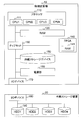
- FIG. 3 is a diagram illustrating an example of a hardware configuration of a computer system according to the first embodiment.
- 1 is a diagram illustrating an example of a logical configuration of a computer system according to a first embodiment. It is a figure which shows an example of the management information of Example 1. It is a figure which shows the mapping relationship and structure of a common area
- FIG. FIG. 6 is a sequence diagram illustrating a flow of processing using a shared area of the computer system according to the first embodiment.
- FIG. 6 is a sequence diagram illustrating a flow of processing using a shared area of the computer system according to the first embodiment.
- 7 is a flowchart illustrating an example of a mapping process executed by an agent according to the first embodiment.
- FIG. 1 is a diagram illustrating an example of a hardware configuration of the computer system according to the first embodiment.
- the computer system includes a physical computer 10 and an external storage device 20.
- the physical computer 10 is connected to the external storage apparatus 20 directly or via a network.
- SAN etc. comprised by FC (Fibre Channel) can be considered.
- the physical computer 10 includes a processor 110, a RAM 120, a chip set 130, an FPGA 140, an internal storage device 150, a power supply unit 160, and an I / O device 170.
- the processor 110 reads a program (instruction) stored in the RAM 120 and executes the read program (instruction).
- the processor 110 has a plurality of CPU cores 111. Functions such as an OS are realized by the processor 110 executing the program.
- processing is mainly described with respect to a program, it indicates that the program is being executed by the processor 110.
- the RAM 120 stores a program executed by the processor 110 and information necessary for executing the program.
- the RAM 120 includes a work area for each program.
- the chip set 130 manages input / output of data among the processor 110, the RAM 120, and the I / O device 170.
- the FPGA 140 is a circuit that performs a predetermined calculation. In this embodiment, the FPGA 140 performs data transfer and the like. Note that the FPGA 140 includes a RAM 141.
- the internal storage device 150 is a non-volatile storage medium, for example, HDD (Hard Disk Drive) or SSD (Solid State Drive).
- HDD Hard Disk Drive
- SSD Solid State Drive
- data stored in the RAM 141 is stored in the internal storage device 150 when the power is unexpectedly shut off.
- data stored in the RAM 1120 may be stored in the internal storage device 150.
- the power supply unit 160 controls the power supply of the physical computer 10.
- the I / O device 170 is a device for inputting information from outside and outputting information to the outside by connecting to an external device.
- the I / O device 170 may be, for example, NIC, FC HBA, or the like.
- the external storage device 20 stores an OS program, program codes of various applications operating on the OS, data handled by the application, and the like.
- the external storage device 20 includes a plurality of storage media.
- the external storage apparatus 20 includes four HDDs 190 as storage media.
- the physical computer 10 may be connected to a storage system including a plurality of storage media and a controller.
- FIG. 2 is a diagram illustrating an example of a logical configuration of the computer system according to the first embodiment.
- the computer resources of the physical computer 10 are divided, and the divided computer resources are allocated to the host OS 1 (200) and the host OS 2 (210), respectively.
- the computer resource includes the RAM 120.
- the memory area (storage area) of the RAM 120 is divided into two, and the divided memory areas are allocated to the host OS 1 (200) and the host OS 2 (210), respectively.
- the divided memory area is also referred to as a divided RAM.
- the computer resources allocated to the host OS 1 (200) are exclusively used by the host OS 1 (200), and the computer resources allocated to the host OS 2 (210) are exclusively used by the host OS 2 (210). .
- the host OS 1 (200) of this embodiment corresponds to the storage control OS.
- the storage control OS controls read processing and write processing for the external storage apparatus 20.
- the host OS 1 (200) executes backup processing and restore processing between the guest OS 230 and the internal storage device 150.
- the host OS 2 (210) of this embodiment corresponds to a VMM (Virtual Machine Monitor) such as a hypervisor.
- the VMM creates one or more virtual machines (LPAR 220) using a part of the computer resources allocated to the host OS 2 (210) using the virtual machine technology, and starts the guest OS 230 on the created LPAR 220.
- LPAR 220 virtual machines
- an application 232 that performs a predetermined process is further operated.
- the host OS 2 (210) manages the mapping between the host physical address space of the divided RAM assigned to the host OS 2 (210) and the guest physical address space of the logical RAM assigned to the LPAR 220.
- the host physical address space of the divided RAM is an address space indicating the physical location of the divided RAM.
- the guest physical address space of the logical RAM is an address space indicating the physical location of the logical RAM.
- the host OS 1 (200) also manages the host physical address of the divided RAM allocated to itself.
- the guest OS 230 manages mapping between the guest physical address space of the logical RAM and the guest virtual address space.
- the guest virtual address space is an address space indicating the position of the virtual RAM to which the guest OS 230 is assigned to the application 232.
- the LPAR 220 includes a logical processor, a logical RAM (logical memory), and a logical I / O device.
- the host OS 2 (210) of this embodiment allocates the shared area 221 to the LPAR 220.
- the shared area 221 is a memory area used for communication between the application 232 and the host OS 1 (200).
- the host OS 2 (210) of this embodiment has a shared area management unit 211 and a processing unit 212, and holds management information 213.
- the shared area management unit 211 allocates a shared area 221 to the LPAR 220 and manages the shared area 221.
- the shared area management unit 211 divides the shared area 221 into a plurality of blocks, and manages the state of the shared area 221 in units of blocks. In the following description, the block-unit shared area 221 is also simply referred to as a block.
- the processing unit 212 controls communication between the host OS 1 (200) and the guest OS 230 using the shared area 221.
- the management information 213 is information for managing the shared area 221 and is managed by the shared area management unit 211. Details of the management information 213 will be described with reference to FIG.
- the guest OS 230 of this embodiment includes an agent 231.
- the agent 231 passes a request regarding the shared area 221 issued by the application 232 to the host OS 2 (210), and requests the host OS 2 (210) to secure the shared area 221. Further, the agent 231 maps the shared area 221 secured in the virtual address space, and returns the virtual address to which the shared area 221 is mapped to the application 232. As a result, the application 232 can use the shared area 221.
- FIG. 3 is a diagram illustrating an example of the management information 213 according to the first embodiment.
- Management information 213 includes a block ID 301, a guest physical address 302, a host physical address 303, a size 304, and an allocation state 305.
- Block ID 301 is a block identification number.
- the guest physical address 302 is a block start address in the guest physical address space.
- the host physical address 303 is a start address of a block in the host physical address space.
- the size 304 is a block size. In this embodiment, it is assumed that the size of all the blocks is the same. Note that the size of each block may be different.
- the allocation state 305 is information indicating whether or not a block is allocated to the application 232. In the allocation state 305 of this embodiment, either “ON” or “OFF” is stored. When the allocation state 305 is “ON”, it indicates that the block is allocated to the application 232. When the allocation state 305 is “OFF”, it indicates that the block is not allocated to the application 232.
- one shared area 221 is allocated to one LPAR 220. Therefore, the host OS 2 (210) holds the same number of management information 213 as the number of LPARs 220.
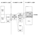
- FIG. 4 is a diagram showing the mapping relationship and structure of the shared area in the first embodiment.
- the memory area of the RAM 120 of the physical computer 10 is divided into two, and the divided memory areas are assigned to the host OS 1 and the host OS 2 respectively.
- Each of the host OS 1 (200) and the host OS 2 (210) manages the allocated memory area as an independent host physical address space.
- the host OS 2 reserves a part of the allocated memory area as a control area for the host OS 2 (210). Further, the host OS 2 (210) secures a part of the allocated memory area as the area of the LPAR 220 and allocates the area to the LPAR 220.
- the LPAR 220 divides the LPAR 220 area into a guest OS 230 area and an LPAR 220 control area.
- the guest OS 230 area includes an MMIO area, an F / W area, a RAM area, and an area for controlling the guest OS 230.
- the host OS 2 (210) allocates the shared area 221 to the control area when the LPAR 220 is activated. That is, a part of the control area is used as the shared area 221.
- the data structure of the shared area 221 includes a data area and a communication area.
- the data area is a memory area for storing data transmitted from the host OS 1 (200) in order to perform restoration using data backed up by the host OS 1 (200).
- the communication area is a memory area used for communication between the application 232 and the host OS 1 (200).
- the data structure of the shared area 221 shown in FIG. 4 shows a logical structure. Therefore, the data area and the communication area may not be continuous memory areas. Note that by allocating the shared area 221 even during normal startup, for example, the host OS 2 (210) and the application 232 can share the memory.
- the shared area 221 is different from the area of the guest OS 230, it is a memory area that is not recognized as a logical RAM by the guest OS 230. Further, since the shared area 221 is included in the memory area assigned to the host OS 2, it is not accessed from the host OS 1 (200) except for communication with the application 232.
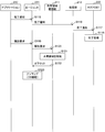
- FIG. 5A and FIG. 5B are sequence diagrams illustrating the flow of processing using the shared area 221 of the computer system according to the first embodiment.
- a restore process using a shared area will be described as an example of a process using a shared area.
- the host OS 1 (200) backs up the data stored in the RAM 120 for caching to the external storage device 20 when the power supply unit 160 of the physical computer 10 is turned off, such as a failure (step S101). Thereafter, the physical computer 10 restarts.
- the shared area management unit 211 of the host OS 2 (210) allocates the shared area 221 to the LPAR 220 when the LPAR 220 is activated (step S102).
- the shared area management unit 211 secures an area for the shared area 221 from the memory area for control among the memory areas allocated to the LPAR 220 when the LPAR 220 is activated.
- the shared area management unit 211 reserves a memory area where addresses in the host physical address space are continuous as the shared area 221. At this time, the shared area management unit 211 divides the reserved memory area into blocks, and assigns an identification number to each block.
- the shared area management unit 211 generates entries for the number of blocks in the management information 213, and sets the identification number assigned to the block ID 301. Further, the shared area management unit 211 sets the start address of each block in the host physical address 303 of each entry, and sets the size of each block in the size 304. Furthermore, the shared area management unit 211 sets “OFF” in the allocation state 305 of each entry.
- the shared area management unit 211 acquires the guest physical address and host physical address of each block based on the address of the reserved memory area, and acquires the guest physical address 302 and host physical address 303 of each entry. Set the guest physical address and host physical address. The above is the description of the processing in step S102.
- the processing of the application 232 is started.
- the application 232 determines whether backup processing has been executed. For example, the above-described determination can be made by making an inquiry to the host OS 1 (200) via the host OS 2 (210). Here, it is determined that the backup process has been executed.
- the application 232 issues a request for securing the shared area 221 to the agent 231 (step S103).
- the reservation request includes the size of the memory area to be reserved.
- the agent 231 issues a request for securing the shared area 221 received from the application 232 to the shared area management unit 211 (step S104).
- the shared area management unit 211 When the shared area management unit 211 receives a request for securing the shared area 221 from the agent 231, the shared area 221 refers to the management information 213 and secures the shared area 221 (block) to be allocated to the guest virtual address space of the application 232 (step S 105). ). That is, a block to be provided to the application 232 is selected. Further, the shared area management unit 211 notifies the agent 231 of the guest physical address to be mapped (step S106).
- the shared area management unit 211 refers to the allocation state 305 of each entry in the management information 213, and searches for a location where entries whose management information 213 is “OFF” continue for the requested size.
- the shared area management unit 211 selects the searched entry group, and sets “ON” in the allocation state 305 of the selected entry group.
- the shared area management unit 211 notifies the agent 231 of values stored in the first block ID 301 and the guest physical address 302 of the selected entry group. At this time, since the address that the shared area management unit 211 passes to the agent is the address to be mapped, the offset to the area used by the application 232 is also notified.
- the agent 231 When the agent 231 receives the guest physical address from the shared area management unit 211, the agent 231 maps the guest physical address to the guest virtual address space (step S107). In this embodiment, the guest physical address is mapped to the guest virtual address using the function of the OS. Specific processing will be described with reference to FIG.
- the agent 231 notifies the mapped guest virtual address to the application 232 (step S108).
- the agent 231 determines the shared area in which the guest virtual address, guest physical address, file descriptor, block identification number, size, etc. of the first block used by the application 232 are secured. Information necessary for release is notified to the application 232.
- the application 232 When receiving the guest physical address from the agent 231, the application 232 issues a processing start request to the host OS 2 (210) using the shared area 221 in order to start communication with the host OS 1 (200). (Step S109).
- the start request includes the size included in the request for securing the shared area 221 issued in step S103 and the block identification number received from the agent 231.
- the agent 231 issues a processing start request received from the application 232 to the processing unit 212 (step S110).
- the processing unit 212 When receiving the processing start request from the agent 231, the processing unit 212 requests the host physical address of the block secured in the shared area management unit 211 (step S111).
- the request for the host physical address includes the block identification number issued in step S108 and input in the start request in step S109.
- the shared area management unit 211 When receiving the request for the host physical address, the shared area management unit 211 notifies the processing unit 212 of the host physical address of the secured block based on the management information 213 (step S112).
- the shared area management unit 211 refers to the management information 213 and searches for an entry in which the block ID 301 matches the block identification number included in the request for the host physical address.
- the shared area management unit 211 notifies the processing unit 212 of the address stored in the host physical address 303 of the retrieved entry.
- the processing unit 212 When receiving the host physical address from the shared area management unit 211, the processing unit 212 notifies the host physical address to the host OS 1 (200) (step S113). At this time, the processing unit 212 also notifies the size included in the input of the start request in step S109 together with the host physical address. Accordingly, the host OS 1 (200) can access the shared area 221 assigned to the application 232.
- the host OS 1 (200) executes processing using the shared area 221 (step S114).
- a restore process using the shared area 221 is executed. Since the restore process is well known, detailed description thereof is omitted.
- the application 232 issues a completion notification to the agent 231 after the restoration process is completed (step S115).
- the agent 231 issues a completion notification received from the application 232 to the processing unit 212 (step S116).
- the processing unit 212 When receiving the completion notification from the agent 231, the processing unit 212 issues a completion notification to the host OS 1 (200) (step S117).
- the host OS 1 (200) When the host OS 1 (200) receives a completion notification from the processing unit 212, the host OS 1 (200) executes a completion process so that the shared area 221 is not accessed thereafter (step S118). Since the completion process is a known process, detailed description thereof is omitted.
- Application 232 issues a release request to agent 231 (step S119).
- the release request includes various information received from the agent 231 in step S108.
- the agent 231 issues the release request received from the application 232 to the shared area management unit 211 (step S120).
- the shared area management unit 211 When the shared area management unit 211 receives a release request from the agent 231, the shared area management unit 211 releases all the blocks allocated to the application 232 (step S121). At this time, the shared area management unit 211 refers to the management information 213 and updates all the allocation statuses 305 of the entries corresponding to the released blocks to “OFF”.
- the shared area management unit 211 notifies the agent 231 of an offset for calculating an address for unmapping (step S122).
- the agent 231 uses the offset to unmap the block from the guest virtual address space (step S123).
- FIG. 6 is a flowchart illustrating an example of the mapping process executed by the agent 231 according to the first embodiment.
- the agent 231 opens the special file (step S201).
- the agent 231 determines whether or not the special file has been successfully opened (step S202).
- the agent 231 determines that an error has occurred and ends the process.
- the agent 231 executes mmap in order to map the guest physical address of the block to the guest virtual address (step S203).
- the agent 231 determines whether mmap is successful (step S204).
- the agent 231 determines that there is an error and ends the process.
- the agent 231 returns a guest virtual address to the application 232 as the mmap execution result (step S205).
- the agent 231 executes mmunmap.
- the application on the LPAR 220 managed by the host OS 2 and the host A shared area for communication with the OS 1 (200) can be secured.
- processing such as communication can be performed between the host OS 1 (200) that uses independent computer resources and the application 232 on the host OS 2.
- the method of using the shared area is not limited to communication between the host OS 1 (200) and the application 232 on the host OS 2.
- the shared area can be used for communication between the host OS 2 and the application 232 or communication between the host OS 2 and the agent 231.
- this invention is not limited to the above-mentioned Example, Various modifications are included. Further, for example, the above-described embodiments are described in detail for easy understanding of the present invention, and are not necessarily limited to those provided with all the described configurations. Further, a part of the configuration of each embodiment can be added to, deleted from, or replaced with another configuration.
- each of the above-described configurations, functions, processing units, processing means, and the like may be realized by hardware by designing a part or all of them with, for example, an integrated circuit.
- the present invention can also be realized by software program codes that implement the functions of the embodiments.
- a storage medium in which the program code is recorded is provided to the computer, and a processor included in the computer reads the program code stored in the storage medium.
- the program code itself read from the storage medium realizes the functions of the above-described embodiments, and the program code itself and the storage medium storing it constitute the present invention.
- Examples of storage media for supplying such program codes include flexible disks, CD-ROMs, DVD-ROMs, hard disks, SSDs (Solid State Drives), optical disks, magneto-optical disks, CD-Rs, magnetic tapes, A non-volatile memory card, ROM, or the like is used.
- program code for realizing the functions described in this embodiment can be implemented by a wide range of programs or script languages such as assembler, C / C ++, Perl, Shell, PHP, Java, and the like.
- the program code is stored in a storage means such as a hard disk or memory of a computer or a storage medium such as a CD-RW or CD-R.
- a processor included in the computer may read and execute the program code stored in the storage unit or the storage medium.
- control lines and information lines indicate those that are considered necessary for the explanation, and do not necessarily indicate all the control lines and information lines on the product. All the components may be connected to each other.
Landscapes
- Engineering & Computer Science (AREA)
- Theoretical Computer Science (AREA)
- Software Systems (AREA)
- Physics & Mathematics (AREA)
- General Engineering & Computer Science (AREA)
- General Physics & Mathematics (AREA)
- Computer Security & Cryptography (AREA)
- Quality & Reliability (AREA)
- Memory System Of A Hierarchy Structure (AREA)
- Stored Programmes (AREA)
- Information Retrieval, Db Structures And Fs Structures Therefor (AREA)
Abstract
Priority Applications (4)
| Application Number | Priority Date | Filing Date | Title |
|---|---|---|---|
| JP2017527033A JP6458146B2 (ja) | 2015-07-08 | 2015-07-08 | 計算機及びメモリ領域管理方法 |
| PCT/JP2015/069628 WO2017006458A1 (fr) | 2015-07-08 | 2015-07-08 | Ordinateur et procédé de gestion de région de mémoire |
| CN201580081422.9A CN107710160B (zh) | 2015-07-08 | 2015-07-08 | 计算机和存储区域管理方法 |
| US15/741,704 US10289564B2 (en) | 2015-07-08 | 2015-07-08 | Computer and memory region management method |
Applications Claiming Priority (1)
| Application Number | Priority Date | Filing Date | Title |
|---|---|---|---|
| PCT/JP2015/069628 WO2017006458A1 (fr) | 2015-07-08 | 2015-07-08 | Ordinateur et procédé de gestion de région de mémoire |
Publications (1)
| Publication Number | Publication Date |
|---|---|
| WO2017006458A1 true WO2017006458A1 (fr) | 2017-01-12 |
Family
ID=57685160
Family Applications (1)
| Application Number | Title | Priority Date | Filing Date |
|---|---|---|---|
| PCT/JP2015/069628 Ceased WO2017006458A1 (fr) | 2015-07-08 | 2015-07-08 | Ordinateur et procédé de gestion de région de mémoire |
Country Status (4)
| Country | Link |
|---|---|
| US (1) | US10289564B2 (fr) |
| JP (1) | JP6458146B2 (fr) |
| CN (1) | CN107710160B (fr) |
| WO (1) | WO2017006458A1 (fr) |
Cited By (3)
| Publication number | Priority date | Publication date | Assignee | Title |
|---|---|---|---|---|
| WO2018181840A1 (fr) * | 2017-03-30 | 2018-10-04 | 日本電気株式会社 | Dispositif de commande, système de commande, procédé de commande et programme |
| EP3580650A4 (fr) * | 2017-03-20 | 2020-04-01 | Huawei Technologies Co., Ltd. | Procédés et appareil pour ressources informatiques sécurisées conteneurisées |
| WO2023047436A1 (fr) * | 2021-09-21 | 2023-03-30 | 日本電信電話株式会社 | Dispositif de traitement d'informations et procédé de traitement d'informations |
Families Citing this family (12)
| Publication number | Priority date | Publication date | Assignee | Title |
|---|---|---|---|---|
| US12248560B2 (en) * | 2016-03-07 | 2025-03-11 | Crowdstrike, Inc. | Hypervisor-based redirection of system calls and interrupt-based task offloading |
| US12339979B2 (en) | 2016-03-07 | 2025-06-24 | Crowdstrike, Inc. | Hypervisor-based interception of memory and register accesses |
| US10387681B2 (en) * | 2017-03-20 | 2019-08-20 | Huawei Technologies Co., Ltd. | Methods and apparatus for controlling access to secure computing resources |
| JP7083717B2 (ja) * | 2018-07-23 | 2022-06-13 | ルネサスエレクトロニクス株式会社 | 半導体装置 |
| US11487674B2 (en) | 2019-04-17 | 2022-11-01 | Rankin Labs, Llc | Virtual memory pool within a network which is accessible from multiple platforms |
| US11061819B2 (en) | 2019-05-28 | 2021-07-13 | Micron Technology, Inc. | Distributed computing based on memory as a service |
| US12436804B2 (en) | 2019-05-28 | 2025-10-07 | Micron Technology, Inc. | Memory as a service for artificial neural network (ANN) applications |
| WO2021113626A1 (fr) * | 2019-12-06 | 2021-06-10 | John Rankin | Langage de programmation de haut niveau faisant appel à une mémoire virtuelle |
| US11580019B2 (en) * | 2020-04-17 | 2023-02-14 | Microsoft Technology Licensing, Llc | Computer memory management in computing devices |
| CN115669022B (zh) | 2020-05-21 | 2026-04-21 | 三星电子株式会社 | 电子设备提供基于测距的服务的方法和电子设备 |
| CN112596642B (zh) * | 2020-12-16 | 2022-06-07 | 维沃移动通信有限公司 | 数据共享方法、装置、设备和可读存储介质 |
| CN113934509B (zh) | 2021-09-02 | 2024-12-31 | 三星(中国)半导体有限公司 | 支持混合虚拟机管理器的系统和运行方法 |
Citations (3)
| Publication number | Priority date | Publication date | Assignee | Title |
|---|---|---|---|---|
| JP2001243080A (ja) * | 2000-03-02 | 2001-09-07 | Hitachi Ltd | 情報処理装置 |
| JP2004258698A (ja) * | 2003-02-24 | 2004-09-16 | Hitachi Ltd | マルチos計算機システムの制御方法 |
| US20150046924A1 (en) * | 2007-10-30 | 2015-02-12 | Vmware, Inc. | Transparent memory-mapped emulation of i/o calls |
Family Cites Families (8)
| Publication number | Priority date | Publication date | Assignee | Title |
|---|---|---|---|---|
| JP3546678B2 (ja) | 1997-09-12 | 2004-07-28 | 株式会社日立製作所 | マルチos構成方法 |
| US20050114595A1 (en) * | 2003-11-26 | 2005-05-26 | Veritas Operating Corporation | System and method for emulating operating system metadata to provide cross-platform access to storage volumes |
| KR101288700B1 (ko) | 2008-03-14 | 2013-08-23 | 미쓰비시덴키 가부시키가이샤 | 멀티 오퍼레이팅 시스템(os) 기동 장치, 컴퓨터 판독 가능한 기록 매체 및 멀티 os 기동 방법 |
| CN101477511B (zh) * | 2008-12-31 | 2010-08-25 | 杭州华三通信技术有限公司 | 一种实现多操作系统共享存储介质的方法和装置 |
| CN101847105B (zh) * | 2009-03-26 | 2013-09-04 | 联想(北京)有限公司 | 一种计算机及多操作系统共享内存的方法 |
| CN103034616B (zh) * | 2012-12-07 | 2015-09-09 | 中国科学院声学研究所 | 一种多个操作系统访问存储介质的方法、计算机 |
| JP6559793B2 (ja) * | 2015-04-10 | 2019-08-14 | グーグル エルエルシー | 共有オブジェクト・レベルにおけるバイナリ変換 |
| US10146572B1 (en) * | 2016-06-15 | 2018-12-04 | Rockwell Collins, Inc. | Resource management in hypervised computer systems |
-
2015
- 2015-07-08 WO PCT/JP2015/069628 patent/WO2017006458A1/fr not_active Ceased
- 2015-07-08 CN CN201580081422.9A patent/CN107710160B/zh active Active
- 2015-07-08 US US15/741,704 patent/US10289564B2/en active Active
- 2015-07-08 JP JP2017527033A patent/JP6458146B2/ja active Active
Patent Citations (3)
| Publication number | Priority date | Publication date | Assignee | Title |
|---|---|---|---|---|
| JP2001243080A (ja) * | 2000-03-02 | 2001-09-07 | Hitachi Ltd | 情報処理装置 |
| JP2004258698A (ja) * | 2003-02-24 | 2004-09-16 | Hitachi Ltd | マルチos計算機システムの制御方法 |
| US20150046924A1 (en) * | 2007-10-30 | 2015-02-12 | Vmware, Inc. | Transparent memory-mapped emulation of i/o calls |
Cited By (6)
| Publication number | Priority date | Publication date | Assignee | Title |
|---|---|---|---|---|
| EP3580650A4 (fr) * | 2017-03-20 | 2020-04-01 | Huawei Technologies Co., Ltd. | Procédés et appareil pour ressources informatiques sécurisées conteneurisées |
| WO2018181840A1 (fr) * | 2017-03-30 | 2018-10-04 | 日本電気株式会社 | Dispositif de commande, système de commande, procédé de commande et programme |
| JP2018169978A (ja) * | 2017-03-30 | 2018-11-01 | 日本電気株式会社 | 制御装置、制御システム、制御方法及びプログラム |
| WO2023047436A1 (fr) * | 2021-09-21 | 2023-03-30 | 日本電信電話株式会社 | Dispositif de traitement d'informations et procédé de traitement d'informations |
| JPWO2023047436A1 (fr) * | 2021-09-21 | 2023-03-30 | ||
| JP7684603B2 (ja) | 2021-09-21 | 2025-05-28 | 日本電信電話株式会社 | 情報処理装置および情報処理方法 |
Also Published As
| Publication number | Publication date |
|---|---|
| JP6458146B2 (ja) | 2019-01-23 |
| CN107710160B (zh) | 2021-06-22 |
| CN107710160A (zh) | 2018-02-16 |
| JPWO2017006458A1 (ja) | 2018-05-10 |
| US20180203805A1 (en) | 2018-07-19 |
| US10289564B2 (en) | 2019-05-14 |
Similar Documents
| Publication | Publication Date | Title |
|---|---|---|
| JP6458146B2 (ja) | 計算機及びメモリ領域管理方法 | |
| US12405816B2 (en) | Virtual machine live migration method and communications device | |
| US9606745B2 (en) | Storage system and method for allocating resource | |
| US8365167B2 (en) | Provisioning storage-optimized virtual machines within a virtual desktop environment | |
| JP4487920B2 (ja) | ブート制御方法および計算機システム並びにその処理プログラム | |
| US9146766B2 (en) | Consistent unmapping of application data in presence of concurrent, unquiesced writers and readers | |
| US8775696B2 (en) | Storage area network access for virtual machines | |
| JP6165964B2 (ja) | 計算機 | |
| US20120246644A1 (en) | Virtual computer system and controlling method of virtual computer | |
| JP6316895B2 (ja) | ホスト側フラッシュストレージデバイスの容量を仮想マシンに利用可能にする技術 | |
| JP2010257274A (ja) | 仮想化環境におけるストレージ管理システム及びストレージ管理方法 | |
| US11593170B2 (en) | Flexible reverse ballooning for nested virtual machines | |
| JP5966466B2 (ja) | バックアップ制御方法、および情報処理装置 | |
| WO2015052836A1 (fr) | Dispositif de stockage et procédé de basculement | |
| WO2015122007A1 (fr) | Ordinateur et procédé d'ordonnancement d'une ressource au moyen d'un hyperviseur | |
| US7500051B2 (en) | Migration of partitioned persistent disk cache from one host to another | |
| WO2016110951A1 (fr) | Système informatique, procédé de gestion de licence, et ordinateur de gestion | |
| JP2013206454A (ja) | 情報処理装置、装置管理方法および装置管理プログラム |
Legal Events
| Date | Code | Title | Description |
|---|---|---|---|
| 121 | Ep: the epo has been informed by wipo that ep was designated in this application |
Ref document number: 15897720 Country of ref document: EP Kind code of ref document: A1 |
|
| ENP | Entry into the national phase |
Ref document number: 2017527033 Country of ref document: JP Kind code of ref document: A |
|
| WWE | Wipo information: entry into national phase |
Ref document number: 15741704 Country of ref document: US |
|
| NENP | Non-entry into the national phase |
Ref country code: DE |
|
| 122 | Ep: pct application non-entry in european phase |
Ref document number: 15897720 Country of ref document: EP Kind code of ref document: A1 |