WO2017006477A1 - Dispositif de prétraitement, et système d'analyse le comportant - Google Patents
Dispositif de prétraitement, et système d'analyse le comportant Download PDFInfo
- Publication number
- WO2017006477A1 WO2017006477A1 PCT/JP2015/069743 JP2015069743W WO2017006477A1 WO 2017006477 A1 WO2017006477 A1 WO 2017006477A1 JP 2015069743 W JP2015069743 W JP 2015069743W WO 2017006477 A1 WO2017006477 A1 WO 2017006477A1
- Authority
- WO
- WIPO (PCT)
- Prior art keywords
- reagent
- sample
- container
- nozzle
- port
- Prior art date
- Legal status (The legal status is an assumption and is not a legal conclusion. Google has not performed a legal analysis and makes no representation as to the accuracy of the status listed.)
- Ceased
Links
Images









Classifications
-
- G—PHYSICS
- G01—MEASURING; TESTING
- G01N—INVESTIGATING OR ANALYSING MATERIALS BY DETERMINING THEIR CHEMICAL OR PHYSICAL PROPERTIES
- G01N35/00—Automatic analysis not limited to methods or materials provided for in any single one of groups G01N1/00 - G01N33/00; Handling materials therefor
- G01N35/10—Devices for transferring samples or any liquids to, in, or from, the analysis apparatus, e.g. suction devices, injection devices
Definitions
- the present invention relates to a pretreatment apparatus that performs pretreatment on a sample.
- the sample when analyzing components contained in a sample derived from a living body such as whole blood, serum, filter paper blood, and urine, the sample may be analyzed after being pretreated by a pretreatment device.
- the pretreatment include a process of removing a specific component unnecessary for analysis from a sample and extracting a necessary component, and a process of concentrating or drying the extracted sample.
- various configurations have been proposed as preprocessing devices that automatically execute such preprocessing (see, for example, Patent Document 1 below).
- Patent Document 1 discloses a configuration in which a plurality of cartridges (separation containers) having a separating agent that allows a sample to pass through and separates a specific component in the sample are held and conveyed by a common conveyance mechanism.
- the plurality of cartridges are sequentially transported by a transport mechanism to a pressure load mechanism provided at a predetermined position, and a sample is extracted by applying pressure to the pressure load mechanism.
- the plurality of tray containers (collection containers) that receive the extraction liquid from the cartridge are transported by a transport mechanism separate from the cartridge below the cartridge, whereby the sample is continuously extracted.
- a reagent is usually added to a sample.
- the reagent is inhaled by, for example, a nozzle, and is added to the sample by discharging a predetermined amount of the reagent from the nozzle.
- the amount of the discharged reagent is likely to vary, which may reduce the analysis accuracy.
- the flow path communicating with the nozzle is filled with water, and a small amount of air that can separate the water and the reagent is sucked into the nozzle. Then inhale the reagent. Even when air is sucked into the nozzle in this way, the reagent may be diluted with water and the reagent, so that the amount of the reagent sucked into the nozzle is the reagent that is actually discharged from the nozzle. It is set to the amount of extra amount added to the amount of.
- a reagent added to a sample containing serum or plasma components contains an organic solvent, and therefore has lower viscosity and surface tension than a water-soluble liquid. Therefore, the reagent is easy to mix with water in the nozzle, and even when air is sucked into the nozzle as described above and an extra amount of reagent is sucked, the reagent is diluted and analysis accuracy is improved. May decrease.
- the present invention has been made in view of the above circumstances, and an object of the present invention is to provide a pretreatment device in which a reagent sucked into a nozzle is not easily diluted and an analysis system including the same.
- the pretreatment apparatus is a pretreatment apparatus that performs pretreatment on a sample, and includes a nozzle, an inhalation treatment unit, and a discharge treatment unit.
- the nozzle adds a reagent to the sample.
- the inhalation processing unit performs a process of inhaling air into the nozzle in a state where the nozzle is filled with water, then inhaling the anti-mixing liquid, inhaling air, and then inhaling the reagent.
- the discharge processing unit performs a process of discharging the reagent in the nozzle and adding it to the sample after the process of the inhalation processing unit.
- the anti-mixing solution is sucked with air sandwiched between the water in the nozzle and the reagent. Accordingly, even when a reagent having a low viscosity and surface tension is sucked into the nozzle, such as a reagent containing an organic solvent, the reagent sucked into the nozzle is not easily diluted. Therefore, it is possible to prevent the analysis accuracy from being lowered due to the thinning of the reagent.
- the pre-processing device may further include a selection receiving unit that receives a selection of the mixing preventing liquid sucked into the nozzle by the processing of the suction processing unit.
- the mixing preventing liquid to be used can be selected from a plurality of types of mixing preventing liquids.
- the optimal mixing preventing liquid can be selected according to the type of reagent, the reagent sucked into the nozzle can be made more difficult to be diluted.
- the pre-processing device may further include a suction amount receiving unit that receives a setting of the amount of the mixing preventing liquid sucked into the nozzle by the processing of the suction processing unit.
- the nozzle can be set by setting the amount of the anti-mixing liquid to an optimum value according to the type of reagent. It is possible to make it difficult for the reagent to be inhaled to be thinner.
- the pretreatment device is based on a combination of a reagent sucked into the nozzle and an anti-mixing solution, and an inhalation amount of air by the inhalation processing unit, an inhalation amount of the anti-mixing solution, an intake speed, a waiting time after inhalation,
- a parameter calculation unit that automatically calculates at least one parameter of the discharge speed by the discharge processing unit may be further provided.
- a parameter that makes it difficult for the reagent sucked into the nozzle to be thinned can be automatically calculated based on the combination of the reagent and the mixing preventing liquid. Therefore, even if it is difficult to set parameters, the reagent can be reliably prevented from being diluted.
- the inhalation processing unit may inhale into the nozzle an amount of reagent obtained by adding an extra amount to the amount of reagent ejected from the nozzle by the processing of the ejection processing unit.
- the extra amount may be included in the at least one parameter.
- the reagent can be more reliably prevented from being diluted.
- the analysis system includes the pretreatment device, the analysis device, and a control unit.
- a sample that has been pretreated in the pretreatment device is introduced into the analysis device.
- the control unit automatically controls the pretreatment device and the analysis device in conjunction with each other.
- the anti-mixing liquid is sucked between the water in the nozzle and the reagent with the air interposed therebetween, the reagent sucked into the nozzle is not easily diluted.
- FIG. 3A is a cross-sectional view showing the AA cross section of FIG. 3B.
- FIG. 4B is a cross-sectional view showing a BB cross section of FIG. 4B. It is sectional drawing which shows the pre-processing kit of the state with which the separation container and the collection container were piled up.
- FIG. 6B is a cross-sectional view showing the XX cross section of FIG. 6A. It is sectional drawing which shows the YY cross section of FIG. 6A. It is sectional drawing which shows the state which installed the pre-processing kit in the filtration port. It is the schematic which shows the structural example of a negative pressure load mechanism. It is the schematic which showed the structural example of the reagent addition mechanism. It is a figure for demonstrating the aspect at the time of inhaling a reagent in a reagent addition nozzle. It is a block diagram which shows an example of the electrical constitution of an analysis system. It is a figure which shows an example of the apparatus status screen displayed on the operation display part.
- FIG. 1 is a schematic front view showing a configuration example of an analysis system according to an embodiment of the present invention.
- This analysis system includes a pretreatment device 1, an LC (liquid chromatograph) 100, and an MS (mass spectrometry device) 200. Samples that have been pretreated by the pretreatment device 1 are sequentially introduced into the LC100 and the MS200. Analysis. That is, the analysis system according to the present embodiment has a configuration in which a liquid chromatograph mass spectrometer (LC / MS) is connected to the pretreatment device 1. However, the configuration is not limited to such a configuration, and the MS 200 may be omitted, so that the sample that has been subjected to the pre-processing by the pre-processing apparatus 1 may be introduced only into the LC 100. It may be configured to be introduced into the analysis apparatus.
- LC liquid chromatograph mass spectrometer
- the pretreatment device 1 performs various pretreatments such as sample dispensing, reagent dispensing, stirring, and filtration on biological samples such as whole blood, serum, filter paper blood, and urine.
- the sample extracted by these pretreatments is introduced into the LC 100 via the autosampler 101 provided in the LC 100.
- the LC 100 includes a column (not shown), and sample components separated in the process of passing the sample through the column are sequentially introduced into the MS 200.
- the MS 200 includes an ionization unit 201 that ionizes a sample introduced from the LC 100 and a mass analysis unit 202 that analyzes the ionized sample.
- the pre-processing device 1 is provided with an operation display unit 1a including a touch panel, for example.
- the analyst can perform input related to the operation of the preprocessing device 1 by operating the display screen of the operation display unit 1a, and can also provide information regarding the operation of the preprocessing device 1 displayed on the display screen of the operation display unit 1a. Can be confirmed.
- the configuration is not limited to the configuration in which the touch panel type operation display unit 1a is provided.
- the display unit configured by a liquid crystal display and the operation unit configured by operation keys or the like are provided separately. May be.
- FIG. 2 is a plan view showing a configuration example of the pretreatment device 1.
- a pretreatment kit consisting of a set of a separation container 50 and a collection container 54 is used for each sample, and pretreatment items (sample dispensing, reagent dispensing) set for each pretreatment kit are used. Note, stirring, filtration, etc.) are performed.
- the separation container 50 constitutes a pretreatment container into which a sample and a reagent are injected.
- the pretreatment apparatus 1 is provided with a plurality of treatment ports for executing each pretreatment item, and the pretreatment kit can be obtained by installing a pretreatment kit containing a sample in any of the treatment ports. A pre-processing item corresponding to each processing port is executed on the sample contained in the container.
- a filtration port 30, a dispensing port 32, a disposal port 34, a stirring port 36a, temperature control ports 38 and 40, a transfer port 43, a washing port 45, and the like are provided in association with each pretreatment item.
- Each of these processing ports constitutes a plurality of preprocessing units that respectively execute a plurality of types of preprocessing.
- the preprocessing item is a preprocessing item necessary for executing the analysis item designated by the analyst.
- the separation container 50 and the collection container 54 constituting the pretreatment kit are transported between the processing ports by the transport arm 24 as a transport unit.
- a holding portion 25 for holding the separation container 50 and the collection container 54 is formed on the distal end side of the transfer arm 24.
- the proximal end side of the transfer arm 24 is held so as to be rotatable about the vertical shaft 29.
- the transfer arm 24 extends in the horizontal direction, and rotates around the vertical axis 29 to move the holding unit 25 so as to draw an arcuate trajectory in the horizontal plane.
- Each processing port, which is the transfer destination of the separation container 50 and the collection container 54, and other ports are all provided on an arc-shaped track drawn by the holding unit 25.
- the sample is dispensed from the sample container 6 into the pretreatment kit.
- a plurality of sample containers 6 in which samples are stored can be installed in the sample installation unit 2, and samples are sequentially collected from each sample container 6 by a sampling arm 20 as a sampling unit.
- a plurality of sample racks 4 that hold a plurality of sample containers 6 are arranged in a ring shape in the sample placement unit 2.
- the sample placement unit 2 moves each sample rack 4 in the circumferential direction by rotating in a horizontal plane. Thereby, each sample container 6 can be sequentially moved to a predetermined sampling position.
- the sampling position is located on the trajectory of the sampling nozzle 20a provided at the tip of the sampling arm 20, and a sample is collected from the sample container 6 by the sampling nozzle 20a at the sampling position.
- the sampling arm 20 can rotate in a horizontal plane around a vertical shaft 22 provided on the base end side, and can move up and down along the vertical shaft 22 in the vertical direction.
- the sampling nozzle 20a is held vertically downward at the tip of the sampling arm 20, and according to the operation of the sampling arm 20, a circular orbital movement in the horizontal plane or vertical movement is performed. Is called.
- a dispensing port 32 is provided at a position on the orbit of the sampling nozzle 20a and on the orbit of the holding unit 25 of the transfer arm 24.
- the dispensing port 32 is a port for dispensing a sample to the unused separation container 50 from the sampling nozzle 20a.
- the unused separation container 50 is transported to the dispensing port 32 by the transport arm 24.
- a reagent installation unit 8 for installing the reagent container 10 is provided at the center of the sample installation unit 2 where the sample racks 4 are arranged in an annular shape.
- the reagent in the reagent container 10 installed in the reagent installation unit 8 is collected by the reagent arm 26.
- the base end portion of the reagent arm 26 is supported by a vertical shaft 29 that is common to the transfer arm 24, and can be rotated in a horizontal plane around the vertical shaft 29, and in the vertical direction along the vertical shaft 29. It can move up and down.
- a reagent addition nozzle 26 a is held vertically downward at the tip of the reagent arm 26, and the reagent addition nozzle 26 a is held in the horizontal plane in accordance with the operation of the reagent arm 26. The movement which draws the same circular arc-shaped orbit or the vertical movement in the vertical direction is performed.
- the reagent installing unit 8 can be rotated in a horizontal plane independently of the sample installing unit 2.
- a plurality of reagent containers 10 are arranged in an annular shape in the reagent installing unit 8, and each reagent container 10 moves in the circumferential direction as the reagent installing unit 8 rotates. Thereby, the desired reagent container 10 can be moved to a predetermined reagent collection position.
- the reagent collection position is located on the trajectory of the reagent addition nozzle 26a provided at the tip of the reagent arm 26, and the reagent is collected from the reagent container 10 by the reagent addition nozzle 26a at the reagent collection position.
- the reagent in the reagent container 10 is added to the sample in the separation container 50 by being sucked by the reagent addition nozzle 26a and then dispensed to the separation container 50 installed in the dispensing port 32. .
- the separation container 50 and the recovery container 54 are held by a container holding part 12 provided at a position different from the sample setting part 2 and the reagent setting part 8.
- a container holding part 12 In the container holding part 12, a plurality of (48 in the example of FIG. 2) holding a plurality of sets of pretreatment kits in a state where unused separation containers 50 and recovery containers 54 are stacked are arranged in an annular shape. Each of the positions 53 is held.
- the container holding unit 12 includes a rotating unit 14 that rotates in a horizontal plane, and a plurality of container racks 16 that can be attached to and detached from the rotating unit 14.
- Each container rack 16 can hold a plurality of pretreatment kits.
- the plurality of container racks 16 are arranged on the rotating unit 14 in an annular shape.
- An annular holding region for holding a plurality of pretreatment kits is formed by the plurality of container racks 16 arranged side by side in an annular shape.
- the rotating unit 14 displaces each container rack 16 in the circumferential direction of the holding region by rotating in a horizontal plane. Thereby, a plurality of pretreatment kits can be sequentially moved to a predetermined transport position.
- the transfer position is located on the track of the holding unit 25 provided at the tip of the transfer arm 24, and the separation container 50 or the collection container 54 is held by the holding unit 25 at the transfer position, and the transfer destination To the next port.
- the pretreatment kit (separation container 50 or collection container 54) held at each holding position 53 of the container holding unit 12 is unloaded from the transfer position in a certain order and used, so that the pretreatment is performed. It is done sequentially.
- the fixed order is not particularly limited. For example, the order of the plurality of container racks 16 is determined, and the order of the plurality of holding positions 53 is determined in each container rack 16. Therefore, after the pretreatment kits held at all the holding positions 53 of any one of the container racks 16 are unloaded, the pretreatment kits held at the holding positions 53 of the next container rack 16 are sequentially unloaded.
- the Rukoto Although not shown in FIG. 2, each holding position 53 is displayed with a number associated with the fixed order.
- each container rack 16 can be individually attached to and detached from the rotating unit 14. As a result, even when the separation container 50 or the collection container 54 held in any one of the container racks 16 is being processed, the other container rack 16 can be attached and detached to perform another operation. Therefore, the preprocessing efficiency can be improved.
- the separation container 50 and the collection container 54 are not limited to the configuration in which the separation container 50 and the collection container 54 are held by the container holding unit 12 via the container rack 16, and may be configured to be directly held by the container holding unit 12, for example. .
- the separation container 50 and the collection container 54 are not limited to the structure in which the separation container 50 and the collection container 54 are held by the container holding unit 12 in a state of being overlapped with each other. There may be.
- the plurality of container racks 16 is not limited to a configuration in which the plurality of container racks 16 are arranged in an annular shape, and for example, a configuration in which the plurality of container racks 16 are arranged in an arc shape may be employed. In this case, a plurality of separation containers 50 and recovery containers 54 are held in an arc-shaped holding area instead of an annular shape.
- an analyst can install a plurality of types (for example, two types) of separation containers 50 provided with separation layers having different separation performances. These separation containers 50 are selectively used according to the analysis item of the sample, and the separation container 50 corresponding to the analysis item designated by the analyst is selected from the container holding unit 12 and conveyed.
- the analysis item is a type of analysis that is subsequently performed using the sample that has been pre-processed by the pre-processing apparatus 1, for example, a type of analysis that is performed by the LC 100 or the MS 200.
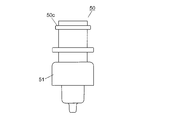
- FIG. 3A is a side view showing a configuration example of the separation container 50.
- FIG. 3B is a plan view of the separation container 50 of FIG. 3A.
- FIG. 3C is a cross-sectional view showing the AA cross section of FIG. 3B.
- FIG. 4A is a side view showing a configuration example of the collection container 54.
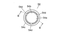
- 4B is a plan view of the collection container 54 of FIG. 4A.
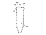
- 4C is a cross-sectional view showing a BB cross section of FIG. 4B.
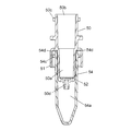
- FIG. 5 is a cross-sectional view showing the pretreatment kit in a state where the separation container 50 and the collection container 54 are overlaid.
- the separation container 50 is a cylindrical container having an internal space 50a for storing a sample and a reagent.
- a separation layer 52 is provided at the bottom of the internal space 50a.
- the separation layer 52 is a separation agent or a separation membrane having a function of selectively separating a specific component in a sample by allowing the sample to pass through and reacting with the specific component physically or chemically, for example.
- separating agent for example, ion exchange resin, silica gel, cellulose, activated carbon and the like can be used.
- the separation membrane include PTFE (polytetrafluoroethylene) membrane, nylon membrane, polypropylene membrane, PVDF (polyvinylidene fluoride) membrane, acrylic copolymer membrane, mixed cellulose membrane, nitrocellulose membrane, polyethersulfone membrane, An ion exchange membrane, a glass fiber membrane, etc. can be used.
- the deproteinization filter for removing the protein in the sample by filtration
- PTFE separation membrane
- an acrylic copolymer membrane or the like can be used as the deproteinization filter (separation membrane) for removing the protein in the sample by filtration
- a prefilter (not shown) may be provided above the separation layer 52 in order to prevent clogging of the deproteinization filter.
- a prefilter for example, a nylon film, a polypropylene film, a glass fiber film, or the like can be used.
- the prefilter is for removing insoluble substances and foreign matters having a relatively large particle diameter from the sample. This prefilter can prevent the deproteinization filter from being clogged with insoluble substances and foreign matters having a relatively large particle size.
- An opening 50b for injecting a sample or a reagent is formed on the upper surface of the separation container 50. Further, an extraction port 50 d for extracting the sample that has passed through the separation layer 52 is formed on the lower surface of the separation container 50. On the upper part of the outer peripheral surface of the separation container 50, a flange portion 50c for engaging the holding portion 25 of the transfer arm 24 is formed so as to protrude in the circumferential direction.
- a skirt portion 51 that contacts the edge of the filtration port 30 when the separation container 50 is accommodated in the filtration port 30 together with the recovery container 54 is provided at the center of the outer peripheral surface of the separation container 50.
- the skirt portion 51 protrudes in the circumferential direction from the outer peripheral surface of the separation container 50 and is formed in an L-shaped cross section so as to extend downward therefrom, thereby forming a certain space between the outer peripheral surface of the separation container 50. is doing.
- the collection container 54 is a cylindrical container that houses the lower part of the separation container 50 and collects the sample extracted from the extraction port 50d of the separation container 50.
- An opening 54 b for inserting the lower part of the separation container 50 is formed on the upper surface of the collection container 54.
- an internal space 54 a that accommodates a portion of the separation container 50 below the skirt portion 51 is formed.
- a flange part 54 c for engaging the holding part 25 of the transfer arm 24 is formed on the upper part of the outer peripheral surface of the collection container 54 so as to protrude in the circumferential direction.
- the separation container 50 and the collection container 54 are overlapped as shown in FIG. 5, the upper part of the collection container 54 enters the inside of the skirt portion 51.
- the outer diameter of the separation container 50 is smaller than the inner diameter of the collection container 54. Thereby, a slight gap is formed between the outer peripheral surface of the separation container 50 accommodated in the internal space 54 a of the recovery container 54 and the inner peripheral surface of the recovery container 54.
- the separation container 50 and the recovery container 54 are installed in a state where the lower part of the separation container 50 is accommodated in the recovery container 54 (state in FIG. 5).
- notches 54d are formed on the upper edge of the collection container 54. Therefore, the separation container 50 and the collection container 54 are overlapped as shown in FIG. 5 so that the collection container 54 can be collected through the notch 54 even when the upper surface of the collection container 54 is in contact with the inner surface of the skirt portion 51.
- the inside and outside of the container 54 can be communicated.
- the number of notches 54d is not limited to three, and may be two or less, or four or more.
- the notch 54d not only the notch 54d but the structure in which the small hole was formed may be sufficient, for example.
- the filtration port 30 is provided inside the container holding part 12. That is, an annular or arc-shaped holding region is formed by the plurality of container racks 16 arranged side by side on the outer periphery of the filtration port 30, and the plurality of separation containers 50 and the collection containers 54 are held in the holding region. Yes.
- the holding region of the separation container 50 and the recovery container 54 is formed in an annular shape or an arc shape, and the installation space for the filtration port 30 is secured in the empty space in the center portion, thereby making the configuration more compact. Can do.
- the separation container 50 and the collection container 54 are held in the holding region in a stacked state, it is not necessary to provide the separation container 50 and the collection container 54 separately. Therefore, more separation containers 50 and recovery containers 54 can be held in a small holding area. Thereby, the holding
- the distance between the plurality of separation containers 50 and the collection containers 54 held in the holding area and the filtration port 30 can be relatively increased. Can be shortened. Thereby, since the time which conveys the separation container 50 and the collection
- the filtration port 30 constitutes a filtration unit that separates the sample by the separation layer 52 by applying pressure to the sample in the separation container 50.
- two filtration ports 30 are provided side by side on the track of the holding unit 25 of the transport arm 24.
- the separation container 50 and the collection container 54 are installed in each filtration port 30 in a state of being overlapped as shown in FIG. 5, and the sample separated by the separation layer 52 in the separation container 50 by the negative pressure is contained in the collection container 54. It has come to be collected.
- the separation container 50 and the collection container 54 are not limited to the structure in which the separation container 50 and the collection container 54 are installed in each filtration port 30 in a state of being overlapped with each other, but the structure in which the separation container 50 and the collection container 54 are individually installed. There may be. Further, the number of filtration ports 30 is not limited to two, and may be one or three or more.
- Three stirring ports 36 a are provided in the stirring unit 36 provided in the vicinity of the container holding unit 12, for example, on the track of the holding unit 25 of the transfer arm 24.
- the stirring unit 36 has a mechanism for individually operating each stirring port 36a in a horizontal plane. By such a mechanism, the sample in the separation container 50 arranged in each stirring port 36a can be stirred.
- the number of stirring ports 36a is not limited to three, and may be two or less, or four or more.
- the temperature control ports 38 and 40 are provided, for example, in a thermally conductive block whose temperature is controlled by a heater and a Peltier element, and the temperature of the separation container 50 or the recovery container 54 accommodated in the temperature control ports 38 and 40 is constant. Adjusted to temperature.
- the temperature control port 38 is for the separation container 50, and, for example, four temperature adjustment ports 38 are arranged side by side on the track of the holding unit 25 of the transfer arm 24.
- the temperature control port 40 is for the recovery container 54, and four temperature control ports 40 are arranged side by side on the track of the holding portion 25 of the transfer arm 24, for example, similarly to the temperature control port 38 for the separation container 50.
- the number of temperature control ports 38 and 40 is not limited to four, but may be three or less, or may be five or more.
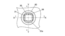
- FIG. 6A is a plan view showing a configuration example of the filtration port 30.
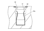
- 6B is a cross-sectional view showing the XX cross section of FIG. 6A.
- 6C is a cross-sectional view showing the YY cross section of FIG. 6A.
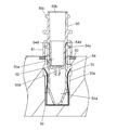
- FIG. 6D is a cross-sectional view showing a state where the pretreatment kit is installed in the filtration port 30.
- the filtration port 30 is composed of, for example, a recess, and the recess constitutes an installation space 30a for installing the pretreatment kit. That is, as shown in FIG. 6D, the separation container 50 and the collection container 54 conveyed from the container holding unit 12 by the conveyance arm 24 are installed in the installation space 30a so as to overlap each other. At this time, the collection container 54 is first accommodated in the installation space 30a, and then the lower part of the separation container 50 is accommodated in the internal space 54a of the recovery container 54.
- a holding member 31 that holds the collection container 54 so as to be sandwiched is provided.
- the holding member 31 is, for example, a U-shaped metal member that is open at the top, and constitutes two leaf springs in which two arms extending upward can be elastically displaced in the inner diameter direction of the filtration port 30. is doing.
- the two leaf spring portions of the holding member 31 have, for example, a curved shape or a bent shape that is recessed inward so that the interval between the upper end portion and the lower end portion is the narrowest.
- the distance between the two leaf spring portions is larger than the outer diameter of the recovery container 54 at the upper end and the lower end, and smaller than the outer diameter of the recovery container 54 at the narrowest distance.
- the two leaf springs of the holding member 31 are lowered as the collection container 54 descends. The portion is opened, and the collection container 54 is held in the installation space 30a by the elastic force.
- the collection container 54 is equally pressed from two opposing directions by the two leaf spring portions of the holding member 31 and is held in the central portion of the installation space 30a.
- the holding member 31 is fixed in the installation space 30a so that it does not float with the recovery container 54 when the recovery container 54 is taken out.
- a ring-shaped sealing member 60 having elasticity is provided at the edge of the upper opening of the filtration port 30.
- the sealing member 60 is fitted, for example, in a recess provided at the edge of the upper surface opening of the filtration port 30.
- the material of the sealing member 60 is an elastic material such as silicone rubber or EPDM (ethylene-propylene-diene rubber).
- the pressure reducing flow path 56 communicates with the installation space 30a from the bottom surface of the filtration port 30.
- a flow path 57 of the negative pressure load mechanism 55 is connected to the flow path 56.
- the negative pressure load mechanism 55 includes a vacuum pump, for example, and constitutes a negative pressure load portion that loads a negative pressure into the installation space 30a. If the inside of the installation space 30a is decompressed by the negative pressure load mechanism 55 in a state where the separation container 50 and the collection container 54 are accommodated in the filtration port 30, the inside of the installation space 30a becomes negative pressure.
- the internal space 54a of the recovery container 54 is formed through a notch 54d of the recovery container 54 and a gap between the inner peripheral surface of the recovery container 54 and the outer peripheral surface of the separation container 50.
- FIG. 7 is a schematic diagram showing a configuration example of the negative pressure load mechanism 55.
- the two filtration ports 30 are connected to a common vacuum tank 66.
- Each filtration port 30 and the vacuum tank 66 are connected by a flow path 57, and a pressure sensor 62 and a three-way valve 64 are provided in each flow path 57.
- the pressure in the installation space 30 a of each filtration port 30 is detected by each pressure sensor 62.
- Each three-way valve 64 is in a state in which the filtration port 30 and the vacuum tank 66 are connected, in a state in which the filtration port 30 side of the flow path 57 is opened to the atmosphere (state in FIG. 7), or in the flow path 57 It can switch to either the state which sealed the edge part by the side of the filtration port 30.
- a pressure sensor 68 is connected to the vacuum tank 66 and a vacuum pump 58 is connected via a three-way valve 70. Therefore, by switching the three-way valve 70, the vacuum pump 58 can be connected to the vacuum tank 66 as needed, and the pressure in the vacuum tank 66 can be adjusted.
- a pressure sensor 62 is connected between the filtration port 30 and the vacuum tank 66 to detect the pressure in the installation space 30 a of the filtration port 30.
- the value of is adjusted to be a predetermined value.
- the end of the flow path 57 on the filtration port 30 side is sealed.
- the installation space 30a of the filtration port 30 becomes a sealed system, and the sample is extracted by maintaining the reduced pressure state in the installation space 30a.
- the pretreatment apparatus 1 is provided with a sample transfer unit 42 for transferring the sample extracted in the collection container 54 to the autosampler 101 side.
- the sample transfer unit 42 includes a moving unit 44 that moves in one direction (the arrow direction in FIG. 2) in the horizontal plane, and a transfer port 43 for installing the collection container 54 is provided on the upper surface of the moving unit 44. It has been.
- the moving unit 44 moves by the operation of a drive mechanism having a rack and pinion mechanism, for example.
- the transfer port 43 is arranged on the track of the holding unit 25 of the transfer arm 24 (position indicated by a solid line in FIG. 2).
- the collection container 54 is installed in the transfer port 43 by the transfer arm 24 and the collection container 54 is collected from the transfer port 43.
- the moving unit 44 moves to the outside of the pretreatment apparatus 1.
- the transfer port 43 is disposed at a position adjacent to the autosampler 101 (a position indicated by a broken line in FIG. 2). In this state, the sample in the collection container 54 is inhaled by the sampling nozzle provided in the autosampler 101.
- the moving unit 44 When the sample inhalation by the autosampler 101 is completed, the moving unit 44 is returned to the original position (the position indicated by the solid line in FIG. 2), and the collection container 54 is collected by the transfer arm 24.
- the used collection container 54 is transported to the disposal port 34 by the transport arm 24 and discarded.
- the disposal port 34 is disposed in the vicinity of the dispensing port 32 on the track of the holding unit 25 of the transfer arm 24, and the used separation container 50 and the collection container 54 are discarded.
- a cleaning port 45 for cleaning the sampling nozzle 20a is provided on the orbit of the sampling nozzle 20a.
- a cleaning port for cleaning the reagent addition nozzle 26a is provided on the orbit of the reagent addition nozzle 26a.
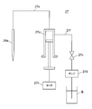
- FIG. 8 is a schematic view showing a configuration example of the reagent addition mechanism 27.
- the reagent addition mechanism 27 is a mechanism for adding a reagent to a sample, and includes a syringe 27a, a motor 27b, a valve 27c, a pump 27d, and the like in addition to the reagent arm 26 and the reagent addition nozzle 26a described above.
- the reagent addition nozzle 26a is connected to the syringe 27a via the first flow path 27e.
- the syringe 27a is driven by a motor 27b. By driving the syringe 27a, the liquid or gas can be sucked from the tip of the reagent addition nozzle 26a, or the sucked liquid or gas can be discharged from the tip of the reagent addition nozzle 26a.
- a valve 27c and a pump 27d are connected to the syringe 27a via a second flow path 27f. If the pump 27d is driven with the valve 27c opened, the pump 27d sucks water into the second flow path 27f, and draws water from the tip of the reagent addition nozzle 26a via the syringe 27a and the first flow path 27e. Can be discharged. On the other hand, when driving the syringe 27a, the valve 27c is closed.
- FIG. 9 is a view for explaining an aspect when the reagent is sucked into the reagent addition nozzle 26a.
- valve 27c When inhaling the reagent into the reagent addition nozzle 26a, first, the valve 27c is opened and the pump 27d is driven to discharge water 28a from the tip of the reagent addition nozzle 26a. This operation is performed, for example, after the reagent addition nozzle 26a is moved to a cleaning port (not shown). When the valve 27c is closed, water is filled from the tip of the reagent addition nozzle 26a to the first flow path 27e, the syringe 27a, and the second flow path 27f.
- the syringe 27a is driven in a state where the tip of the reagent addition nozzle 26a is not in contact with the liquid.
- a small amount of air 28b is sucked from the tip of the reagent addition nozzle 26a.
- the reagent addition nozzle 26a moves into a container (not shown) for storing the mixing prevention liquid, and the syringe 27a is driven in a state where the tip of the reagent addition nozzle 26a is in contact with the mixing prevention liquid.
- a small amount of the mixing preventing liquid 28c is inhaled.
- the mixing preventing liquid 28c is a liquid for preventing the reagent sucked into the reagent adding nozzle 26a from being mixed with the water 28a.
- the mixing preventing liquid 28c may be the same reagent as the reagent sucked into the reagent adding nozzle 26a, or may be another reagent or a dedicated liquid. Specifically, methanol, acetonitrile or the like can be used as the mixing preventing liquid 28c.
- the syringe 27a After sucking the mixing preventing liquid 28c, the syringe 27a is driven after the tip of the reagent addition nozzle 26a is not in contact with the liquid. As a result, a small amount of air 28d is sucked from the tip of the reagent addition nozzle 26a. Then, the reagent addition nozzle 26a moves into the reagent container 10 of the reagent installing unit 8, and the syringe 27a is driven in a state in which the tip is in contact with the reagent contained in the reagent container 10, whereby the reagent 28e. Is inhaled.
- the reagent 28e sucked into the reagent addition nozzle 26a is an amount of a reagent obtained by adding an extra amount 28g to the amount of reagent to be discharged thereafter (required amount 28f).
- the extra amount 28g is a liquid for preventing the necessary amount 28f of the reagent from being mixed with the water 28a or the mixing preventing liquid 28c. This completes the liquid and gas suction process into the reagent addition nozzle 26a.
- the reagent addition nozzle 26a is moved to the dispensing port 32, and the syringe 27a is driven to discharge the necessary amount 28f of the reagent into the separation container 50.
- the extra amount 28g remaining in the reagent addition nozzle 26a, the mixing preventing liquid 28c, the air 28b and 28d, and the water 28a are discarded by driving the syringe 27a.
- FIG. 10 is a block diagram showing an example of the electrical configuration of the analysis system.
- port refers to a plurality of types of ports such as the filtration port 30, the dispensing port 32, the agitation port 36a, the temperature control ports 38 and 40, and the transfer port 43 in which the separation container 50 or the recovery container 54 is installed. Means one of them.
- the operations of the sample transfer unit 42 and the negative pressure load mechanism 55 are controlled by the control unit 84.
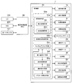
- the control unit 84 includes, for example, a CPU (Central Processing Unit), and when the CPU executes a program, the preprocessing unit 84a, the processing status management unit 84b, the random access unit 84c, the selection receiving unit 84d, and the inhalation amount receiving unit 84f, display control means 84g, parameter calculation means 84h, and the like.
- a CPU Central Processing Unit
- an arithmetic processing device 90 configured by a personal computer (PC) or a dedicated computer is connected to the control unit 84, and the analyst can manage the preprocessing device 1 via the arithmetic processing device 90.
- the arithmetic processing unit 90 is connected not only to the preprocessing unit 1 but also to the LC 100 and the MS 200 into which the sample that has been pre-processed by the pre-processing unit 1 is introduced, the autosampler 101 that injects the sample into the LC 100, and the like.
- the arithmetic processing device 90 can automatically control these devices in conjunction with each other.
- a plurality of sample containers are installed in the sample installation unit 2, and the samples accommodated in these sample containers should be sequentially dispensed into the separation container 50 and executed on the samples.
- the separation container 50 is conveyed to the port corresponding to the pretreatment item.
- the preprocessing unit 84a executes a predetermined process at that port.
- the pre-processing unit 84a includes an inhalation processing unit 84m and a discharge processing unit 84n for performing processing related to reagent dispensing.
- the suction processing means 84m performs processing for sucking liquid and gas into the reagent addition nozzle 26a by driving the motor 27b, the valve 27c and the pump 27d in the manner described with reference to FIG.
- the inhalation processing unit 84m inhales the air 28b into the reagent addition nozzle 26 in the state where the reagent addition nozzle 26 is filled with the water 28a, and then sucks the mixing prevention liquid 28c and again sucks the air 28d. After that, it functions as an inhalation processing unit that performs a process of inhaling the reagent 28e. Further, the discharge processing unit 84n functions as a discharge processing unit that performs a process of discharging the reagent 28e in the reagent addition nozzle 26 by the required amount 28f and adding it to the sample after the process of the inhalation processing unit 84m.
- the random access means 84c confirms the status of preprocessing at each port, and operates the transport arm 24 so as to transport the separation container 50 that has been preprocessed at that port to the port for performing the next preprocessing. To control. That is, the random access means 84c confirms the pretreatment item to be performed next for each sample, confirms the vacancy status of the port corresponding to the pretreatment item, and if there is a vacancy, the separation container containing the sample 50 or the collection container 54 is transported to the port. When there is no available port corresponding to the pretreatment item to be performed next for each sample, the random access means 84c sets the target separation container 50 or the recovery container 54 as the port as soon as the port is available. To transport.
- the processing status management means 84b manages the availability of each port and the processing status at each port.
- the availability of each port can be managed by storing in which port the separation container 50 or the collection container 54 is installed. Further, a sensor for detecting whether or not the separation container 50 or the collection container 54 is installed at each port may be provided, and the availability of each port may be managed based on a signal from the sensor.
- the processing status at each port can be managed by whether or not the time required for the pre-processing executed at the port has elapsed since the separation container 50 or the recovery container 54 was installed at the port.
- the status of processing at the transfer port 43 may be managed depending on whether or not a signal indicating that sample inhalation has ended is received from the autosampler 101 side.
- the random access means 84c is configured to be used in order from the port with the highest priority. For example, when both of the two filtration ports 30 are vacant when the sample is filtered, the collection container 54 is installed in the filtration port 30 having a high priority, and the separation container 50 is placed on the collection container 54. Is installed.
- the analyst When analyzing the sample, the analyst selects the analysis item of the sample by operating the operation display unit 1a.
- the analysis item is selected, for example, by the name of the component to be analyzed in LC100 or MS200. Then, the analyst can further set and select a pre-processing item necessary for executing the analysis item for the selected analysis item by further operating the operation display unit 1a. That is, for the selected analysis item, one or a plurality of arbitrary preprocessing items can be selected and set to be executed in the preprocessing device 1.
- the required amount 28g of the reagent 28e to be added to the sample is set, and the mixture that is inhaled into the reagent addition nozzle 26 by the operator operating the operation display unit 1a.
- the type and amount of the prevention liquid 28c can be set.
- the selection receiving unit 84d functions as a selection receiving unit that receives the selection when the type of the mixing preventing liquid 28c sucked into the reagent addition nozzle 26 is selected.
- the suction amount receiving unit 84f functions as a suction amount receiving unit that receives the setting of the amount.
- the preprocessing unit 84a, the processing status management unit 84b, and the random access unit 84c constitute a preprocessing execution unit 84e.
- the preprocessing execution unit 84e is configured based on various settings including settings received by the selection receiving unit 84d and the suction amount receiving unit 84f, the preprocessing unit configured by each port, the sampling arm 20, the transport arm 24, and the reagent. The arm 26 and the like are controlled. At this time, the preprocessing execution unit 84e performs control so that a plurality of types of preprocessing set for different samples are executed in parallel.
- the separation container 50 or the recovery container 54 in which different samples are accommodated is sequentially transferred to each port corresponding to a plurality of types of pretreatment, and the pretreatment for each sample is executed in parallel.
- the preprocessing execution unit 84e Based on the management by the processing status management unit 84b, the preprocessing execution unit 84e performs control so that different samples are not preprocessed simultaneously on the same port.
- each port forms an individual preprocessing unit.
- an arbitrary separation container 50 or a collection container 54 is sequentially transported to a plurality of ports (pretreatment units) by the transport arm 24, and preprocessing is performed in parallel at each port. Can be made. Thereby, even if it takes a long time to pre-process any sample, it is possible to advance the pre-processing of another sample first, and it is possible to suppress generation of useless waiting time.
- pre-processing since multiple types of pre-processing and parameters for each pre-processing can be set for each sample, a wide variety of pre-processing can be executed for each sample. Even in such a case, an arbitrary separation container 50 or collection container 54 can be sequentially transported to a plurality of ports by the transport arm 24 to execute pretreatment, and the same port can be used for different samples. Since the pre-processing is controlled so as not to be executed simultaneously, the degree of freedom in setting the pre-processing is high and the pre-processing efficiency can be improved.
- the display control means 84g functions as a display control unit for controlling display on the operation display unit 1a. Under the control of the display control means 84g, various display screens can be switched and displayed on the operation display unit 1a. In the present embodiment, a device status screen for displaying information related to the operation of the preprocessing device 1, a condition setting screen for accepting setting of conditions, and the like are displayed on the operation display unit 1a by the control of the display control unit 84g. The settings received by the selection receiving unit 84d and the inhalation amount receiving unit 84f are also displayed on the operation display unit 1a under the control of the display control unit 84g.
- the parameter calculation unit 84h functions as a parameter calculation unit that automatically calculates various parameters at the time of reagent dispensing based on the combination of the reagent 28e sucked into the reagent addition nozzle 26 and the mixing preventing liquid 28c. That is, at least one of the parameters used at the time of dispensing the reagent is calculated based on the type of the mixing preventing liquid 28c that has been selected by the selection receiving unit 84d.
- the above parameters include the amount of air 28b and 28d sucked into the reagent addition nozzle 26, the amount of mixing prevention liquid 28c sucked, the suction speed, the waiting time after suction, the discharge speed, and the extra amount 28g of reagent 28e. It can be illustrated. Here, the greater the amount of air 28b, 28d and the mixing preventing liquid 28c that is sucked, the more difficult the reagent 28e and the mixing preventing liquid 28c are mixed. Further, the higher the liquid and gas suction speed and the gas discharge speed in the reagent addition nozzle 26, the easier the reagent 28e and the mixing preventing liquid 28c are mixed.
- the parameter calculation unit 84h calculates these parameters so that the reagent 28e and the mixing preventing liquid 28c are most difficult to mix.
- the configuration is not limited to the configuration in which all of the various parameters are calculated by the parameter calculation unit 84h, and any configuration may be used as long as at least one parameter is calculated.
- FIG. 11A is a diagram showing an example of a device status screen 300 displayed on the operation display unit 1a.
- the apparatus status screen 300 is a screen for displaying information related to the operation of the pretreatment apparatus 1.
- the execution status of the pretreatment on the sample in the pretreatment apparatus 1 is displayed.
- a symbol image 301 representing the sample placement unit 2 of the pretreatment apparatus 1 is displayed, and each sample container 6 is associated with the holding position of the sample container 6 in the sample placement unit 2 in the symbol image 301.
- the execution status of the pretreatment for the sample is displayed.
- the symbol image 301 is divided into a plurality of arc-shaped regions in association with a plurality of sample racks 4 arranged in an annular shape, like the actual sample placement unit 2, and a sample container is provided in each arc-shaped region.
- a plurality of switching areas 302 corresponding to 6 are provided.
- the display mode for example, color
- the execution status of the pretreatment for the sample in each sample container 6 is displayed according to the display mode. Yes.
- sample placement unit 2 is not limited to a configuration in which the sample container 6 is placed divided into a plurality of sample racks 4.
- the execution status of the pretreatment for the sample “Awaiting analysis” where the pretreatment has not yet been executed, “In analysis” where the pretreatment has started but the analysis result has not yet been obtained, and the analysis data is obtained normally. Examples thereof include “normal end” obtained, “abnormal end” in which an abnormality occurred during preprocessing or analysis, and “data abnormality” in which the obtained analysis data is abnormal.
- the switching area 302 corresponding to the ten sample containers 6 is switched to the “analysis waiting” display mode, and the switching area 302 corresponding to the two sample containers 6 is switched to the “analyzing” display mode.
- the switching area 302 corresponding to one sample container 6 is switched to the “data abnormality” display mode.
- the operation state of the preprocessing device 1 is displayed at the center of the symbol image 301.
- “analyzing” is displayed because the preprocessing device 1 is operating.
- “stopping” is displayed.
- a preprocessing process display area 303 for displaying a preprocessing process that has been executed for each sample under analysis is provided.
- a preprocessing information display area 304 for displaying information related to the operation of the preprocessing apparatus 1 an LC information display area 305 for displaying information related to the operation of the LC100,
- an MS information display area 306 for displaying information related to the operation of the MS 200 is provided.
- the information displayed in the pretreatment information display area 304 includes the connection state 341 of the pretreatment device 1 with respect to the arithmetic processing device 90, the pressure 342 in the filtration port 30, the number of sets of the separation container 50 and the collection container 54 (the remaining number, 343), temperature 344 of each part of the pretreatment device 1 (such as the reagent cooling unit and the temperature control ports 38 and 40), and the state of the pure water tank for storing water used during washing and dispensing 345, pump state 346 for degassing water used during washing and dispensing, waste liquid tank state 347 for draining water used during washing, used separation container 50 and recovery container 54 are discarded Examples thereof include a state 348 of a waste box to be used, a state 349 of a pump for sending out water to be used at the time of washing and dispensing. At least one of these pieces of information may be displayed in the preprocessing information display area 304, other various parameters set as conditions when the preprocessing device 1 operates, and other information on the preprocessing device 1
- Examples of information displayed in the LC information display area 305 include the connection state 351 of the LC 100 to the arithmetic processing unit 90, the pressure 352 of the pump that sends the sample and the mobile phase to the column, the temperature 353 of the oven that heats the column, etc. Can do.
- the LC information display area 305 at least one of these pieces of information may be displayed, and other various parameters set as conditions when the LC 100 operates, the states of other parts of the LC 100, and the like are displayed. May be. For example, even if the autosampler needle lowering stroke, sample suction speed, needle washing time, pump mobile phase flow rate, mobile phase mixing ratio, column oven upper limit set temperature, etc. are displayed in the LC information display area 305 in the LC 100 Good.
- the pressure, flow rate, and oven temperature of the mobile phase of the pump are preferably displayed as parameters having a great influence on the analysis data.
- Information displayed in the MS information display area 306 includes the connection state 361 of the MS 200 with respect to the arithmetic processing unit 90, the gas flow rate 362 used in the MS 200, the temperature 363 of each part of the MS 200, the degree of vacuum 364 of each part of the MS 200, and the like. It can be illustrated.
- the MS information display area 306 at least one of these pieces of information may be displayed, other various parameters set as conditions when the MS 200 operates, the states of other parts of the MS 200, and the like are displayed. May be.
- MS information nebulizer gas flow rate, drying gas flow rate, interface voltage / current, DL (desolvent tube) temperature, heat block temperature, detector voltage, vacuum degree of each vacuum chamber, CID gas pressure, etc. It may be displayed at 306.
- the nebulizer gas flow rate, the drying gas flow rate, the DL temperature, the heat block temperature, and the degree of vacuum are preferably displayed as parameters that have a large influence on the analysis data.
- At least one of the pre-processing information display area 304, the LC information display area 305, and the MS information display area 306 is provided with abnormal display areas 340, 350, and 360 for displaying abnormal information.
- the pretreatment information display area 304 for example, the connection state 341 of the pretreatment device 1 with respect to the arithmetic processing device 90, the state 345 of a pure water tank for storing water used at the time of washing and dispensing, the time of washing and dispensing
- An abnormality display area 340 is provided in association with a state 349 of a pump for sending out water to be used for cleaning and dispensing.
- an abnormality display area 350 is provided in association with the connection state 351 of the LC 100 with respect to the arithmetic processing unit 90.
- an abnormality display area 360 is provided in association with the connection state 361 of the MS 200 with respect to the arithmetic processing unit 90.
- Each abnormality display area 340, 350, 360 is for displaying the abnormality information when the corresponding state is abnormal.
- the abnormality display areas 340, 350, and 360 have different colors depending on whether the state is normal or abnormal. By displaying, an abnormality is displayed.
- the state of the LC 100 or the MS 200 in which the abnormality information is displayed in the abnormality display areas 350 and 360 is not limited to the connection state 351 and 361, and abnormality can be displayed for other various states.
- the display of the abnormality information in each abnormality display area 340, 350, 360 is not limited to switching by color, and can be performed by various other modes such as switching of lighting or blinking.
- a part of the apparatus status screen 300 (for example, the uppermost part) includes a start key 307 selected when the analysis is started, a pause key 308 selected when the analysis is paused, and an emergency with an alarm in an emergency.
- a screen switching key 310 selected when switching the display of the operation display unit 1a from the apparatus status screen 300 to the condition setting screen is displayed. The analyst can easily start an analysis in response to an instruction from the preprocessing device 1 by selecting a start key 307 after selecting an analysis method registered in advance.
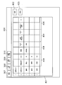
- FIG. 11B is a diagram illustrating an example of the condition setting screen 400 displayed on the operation display unit 1a.
- pretreatment conditions for a sample are set by adding arbitrary pretreatment items (sample dispensing, reagent dispensing, stirring, filtration, temperature control, etc.) to the pretreatment selection area 401. be able to.
- An add key 402 is selected when adding a preprocess item to the preprocess selection area 401, and a delete key 403 is selected when deleting an added preprocess item.
- a condition for executing the preprocessing item For each preprocessing item added to the preprocessing selection area 401, a condition for executing the preprocessing item can be set. Each condition can be set by operating the condition setting area 404 corresponding to each condition provided in the preprocessing selection area 401.
- conditions such as the amount of the reagent 28e, the type of the reagent 28e, the type of the mixing preventing liquid 28c, and the amount of the mixing preventing liquid 28c are set in the condition setting area 404. can do.
- the intake amount of air 28b, 28d, etc. may be set.
- conditions such as stirring time and rotation speed can be set in the condition setting area 404.
- conditions such as filtration time can be set in the condition setting area 404.
- a condition such as a temperature adjustment time can be set in the condition setting area 404, for example.
- parameters are automatically calculated based on the set conditions. Analysis is started. For example, when the types of the reagent 28e and the mixing prevention liquid 28c are selected in the condition setting area 404 for the pretreatment item of “reagent dispensing”, based on the combination of the reagent 28e and the mixing prevention liquid 28c, The parameter is calculated by the parameter calculation means 84h.
- the mixture preventing liquid 28c is sucked between the water 28a and the reagent 28e in the reagent addition nozzle 26 with air 28b and 28d interposed therebetween. Accordingly, even when a reagent 28e having a low viscosity and surface tension is sucked into the reagent addition nozzle 26, such as a reagent 28e containing an organic solvent, the reagent 28e sucked into the reagent addition nozzle 26 is thinned. Hateful. Therefore, it is possible to prevent the analysis accuracy from being lowered due to the thinning of the reagent 28e.
- the anti-mixing liquid 28c to be used can be selected from a plurality of types of anti-mixing liquids 28c.
- the optimal mixing preventing liquid 28c can be selected according to the type of the reagent 28e and the like, the reagent 28e sucked into the reagent addition nozzle 26 can be made more difficult to be diluted.
- the amount of the mixing preventing liquid 28c sucked into the reagent adding nozzle 26 can be set, the amount of the mixing preventing liquid 28c is set to an optimal value according to the type of the reagent 28e, etc. It is possible to make the reagent 28e sucked into the addition nozzle 26 more difficult to thin.
- a parameter that makes it difficult for the reagent 28e to be sucked into the reagent addition nozzle 26 to be thinned can be automatically calculated based on the combination of the reagent 28e and the mixing preventing liquid 28c. Therefore, even if it is difficult to set parameters, the reagent 28e can be reliably prevented from thinning. At this time, if the extra amount 28g is included in the parameter, an optimum value is automatically calculated for the extra amount 28g, so that the reagent can be more reliably prevented from being diluted.
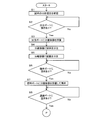
- FIG. 12A and 12B are flowcharts showing an example of the operation of the preprocessing device 1.
- FIG. 12A and FIG. 12B only the flow of preprocessing for one sample is shown, and this preprocessing operation is performed simultaneously and independently with the preprocessing operation of another sample.
- Pre-processing is performed in parallel and independently means that a separation container 50 or a collection container 54 containing another sample is transported while pre-processing is being performed for each sample at each port. This means that the sample is transported to another port by the arm 24 and the pretreatment of the sample is performed independently.
- step S1 the analysis items designated in advance by the analyst are checked for the sample (step S1), and the pre-processing items necessary for executing the analysis items are determined. Then, it is confirmed whether or not the dispensing port 32 is vacant. If the dispensing port 32 is vacant (Yes in step S2), an unused separation container 50 for storing the sample is transferred by the transfer arm 24. It is taken out from the container holding part 12 and installed in the dispensing port 32 (step S3). At this time, the separation container 50 and the collection container 54 are installed in the container holding unit 12 in a state where they are overlapped (the state shown in FIG. 5). Hold and transport to dispensing port 32.
- the sample is dispensed by the sampling nozzle 20a into the separation container 50 in the dispensing port 32 (step S4).
- the sampling nozzle 20a that dispenses the sample into the separation container 50 is prepared for the dispensing of the next sample after being washed in the washing port 45.
- a reagent according to the pretreatment to be performed on the sample is dispensed from the reagent container 10 by the reagent addition nozzle 26a (step S5). Note that the dispensing of the reagent into the separation container 50 may be performed before the dispensing of the sample.
- a reagent dispensing port for dispensing the reagent is provided at a position different from the dispensing port 32, and the separation container 50 is transported to the reagent dispensing port by the transport arm 24, and the reagent dispensing is performed.
- the configuration may be such that reagent is dispensed at the service port.
- Step S6 After the sample and the reagent are dispensed into the separation container 50 in this way, the empty state of the stirring port 36a is confirmed (step S6). If the agitation port 36a is empty (Yes in step S6), the separation container 50 in the dispensing port 32 is conveyed to the vacant agitation port 36a by the conveying arm 24 and agitation processing is performed ( Step S7). This agitation process is performed for a predetermined period of time, whereby the sample and the reagent in the separation container 50 are mixed.
- the availability of the filtration port 30 is confirmed (step S8). If the filtration port 30 is empty (Yes in step S8), the collection container 54 is transported to the filtration port 30 by the transport arm 24 (step S9). At this time, the collection container 54 installed in the filtration port 30 is a collection container 54 that forms a pair with the separation container 50 being stirred at the stirring port 36a, and is installed in a state of being overlapped with the separation container 50 in the container holding unit 12. It is the collection container 54 that had been stored. During the stirring process, another separation container 50 and recovery container 54 can be transported by the transport arm 24.
- Step S10 the separation container 50 is transported from the stirring port 36a to the filtration port 30 by the transport arm 24, and the separation container 50 is installed on the collection container 54 in the filtration port 30 as shown in FIG. 6D.
- Step S10 the separation container 50 is conveyed until the lower end of the skirt portion 51 of the separation container 50 is slightly lower (for example, about 0.1 mm) than the height of the upper surface of the sealing member 60 provided around the filtration port 30.
- the arm 24 is pressed toward the installation space 30a. Thereby, since the sealing member 60 is crushed by the lower end of the skirt part 51, the airtightness between the lower end of the skirt part 51 and the sealing member 60 improves.
- a predetermined negative pressure is applied to the installation space 30 a of the filtration port 30 in which the separation container 50 and the recovery container 54 are installed by the negative pressure load mechanism 55.
- the sample in the separation container 50 is filtered and the sample is extracted into the collection container 54 (step S11).
- the separation arm 50 and the recovery container 54 can be transported by the transport arm 24.
- a temperature adjustment process is incorporated in which the sample in the separation container 50 is maintained at a constant temperature for a certain period of time after the sample in the separation container 50 is stirred. There is also. In that case, after the stirring process is completed, the empty state of the temperature control port 38 is confirmed. If there is an empty space, the separation container 50 is transferred to the empty temperature control port 38. Then, after a certain time has elapsed, the separation container 50 in the temperature control port 38 is conveyed to the filtration port 30 and installed on the recovery container 54 in the filtration port 30.
- the three-way valve 64 (see FIG. 7) is switched to set the inside of the installation space 30a of the filtration port 30 to atmospheric pressure. Then, the used separation container 50 is taken out from the filtration port 30 by the holding unit 25 of the transfer arm 24 and discarded to the disposal port 34 (step S12).
- the transfer port 43 is empty (Yes in step S13), the collection container 54 in the filtration port 30 is transferred to the sample transfer unit 42 by the transfer arm 24 and transferred. Installed on port 43. Then, the moving unit 44 moves to a position on the side of the autosampler 101 arranged adjacently (a position indicated by a broken line in FIG. 2), whereby the collection container 54 is transferred to the side of the autosampler 101 (step S14). . On the autosampler 101 side, the sample is sucked into the collection container 54 transferred from the sample transfer unit 42 by the sampling nozzle.
- the moving unit 44 stops at a position on the autosampler 101 side until the sample inhalation in the autosampler 101 is completed, and when the signal indicating that the sample inhalation is completed is received from the autosampler 101 (Yes in step S15), To the position (the position indicated by the solid line in FIG. 2). After the transfer of the sample is completed, the used collection container 54 is collected from the transfer port 43 by the transfer arm 24 and discarded to the discard port 34 (step S16).
- a temperature control process for maintaining the sample extracted in the collection container 54 at a constant temperature for a fixed time after the sample is filtered.
- the empty state of the temperature control port 40 is confirmed, and if there is an empty space, the collection container 54 is transported to the empty temperature control port 40. Then, after a predetermined time has elapsed, the collection container 54 in the temperature control port 40 is transported to the transfer port 43, and the sample is transferred.
- the container rack 16 may be configured to hold the pretreatment kit in one row, or may be configured to hold in three or more rows.
- the plurality of holding positions 53 are not limited to the configuration arranged in an annular shape, and may be a configuration arranged in another manner such as an arc shape or a linear shape.
- the configuration in which the sample in the separation container 50 is separated by setting the inside of the installation space 30a of the filtration port 30 to a negative pressure has been described.
- the configuration is not limited to such a configuration, and the configuration may be such that the sample in the separation container 50 is separated by pressurizing the inside of the separation container 50.
- control unit 84 and the arithmetic processing unit 90 of the preprocessing device 1 are not limited to the configurations provided separately, and may be configured such that the operation of the entire analysis system is controlled by one control unit. That is, the configuration may be such that the arithmetic processing device 90 is omitted, and information is directly transmitted and received between the preprocessing device 1 and the LC 100 or the MS 200.
- the configuration has been described in which the reagent 28e larger than the required amount 28f is sucked into the reagent addition nozzle 26 as the extra amount 28g.
- the present invention is not limited to such a configuration, and a configuration in which only the necessary amount 28f of the reagent 28e is inhaled may be used as long as the reagent 28e can be sufficiently prevented from being diluted by the mixing preventing liquid 28c.
Landscapes
- Physics & Mathematics (AREA)
- Health & Medical Sciences (AREA)
- Life Sciences & Earth Sciences (AREA)
- Chemical & Material Sciences (AREA)
- Analytical Chemistry (AREA)
- Biochemistry (AREA)
- General Health & Medical Sciences (AREA)
- General Physics & Mathematics (AREA)
- Immunology (AREA)
- Pathology (AREA)
- Automatic Analysis And Handling Materials Therefor (AREA)
Abstract
L'invention concerne un dispositif de prétraitement dans lequel un réactif (28e) aspiré dans une buse d'addition (26) de réactif n'est pas susceptible à l'atténuation, et un système d'analyse comportant le dispositif de prétraitement. Dans un état dans lequel la buse d'addition (26) de réactif est remplie d'eau (28a), une unité de traitement par aspiration procède à un traitement dans lequel, après l'aspiration d'air (28b) dans la buse d'addition (26) de réactif, un liquide de prévention de mélange (28c) est aspiré dans la buse d'addition (26) de réactif, de l'air (28d) est de nouveau aspiré dans la buse d'addition (26) de réactif, et le réactif (28e) est aspiré dans la buse d'addition (26) de réactif. Après le traitement effectué par l'unité de traitement par aspiration, une unité de traitement de décharge procède à un traitement selon lequel le réactif (28e) à l'intérieur de la buse d'addition (26) de réactif est déchargé et ajouté à un échantillon.
Priority Applications (2)
| Application Number | Priority Date | Filing Date | Title |
|---|---|---|---|
| JP2017527049A JP6481761B2 (ja) | 2015-07-09 | 2015-07-09 | 前処理装置及びこれを備えた分析システム |
| PCT/JP2015/069743 WO2017006477A1 (fr) | 2015-07-09 | 2015-07-09 | Dispositif de prétraitement, et système d'analyse le comportant |
Applications Claiming Priority (1)
| Application Number | Priority Date | Filing Date | Title |
|---|---|---|---|
| PCT/JP2015/069743 WO2017006477A1 (fr) | 2015-07-09 | 2015-07-09 | Dispositif de prétraitement, et système d'analyse le comportant |
Publications (1)
| Publication Number | Publication Date |
|---|---|
| WO2017006477A1 true WO2017006477A1 (fr) | 2017-01-12 |
Family
ID=57685161
Family Applications (1)
| Application Number | Title | Priority Date | Filing Date |
|---|---|---|---|
| PCT/JP2015/069743 Ceased WO2017006477A1 (fr) | 2015-07-09 | 2015-07-09 | Dispositif de prétraitement, et système d'analyse le comportant |
Country Status (2)
| Country | Link |
|---|---|
| JP (1) | JP6481761B2 (fr) |
| WO (1) | WO2017006477A1 (fr) |
Cited By (5)
| Publication number | Priority date | Publication date | Assignee | Title |
|---|---|---|---|---|
| JP2017067484A (ja) * | 2015-09-28 | 2017-04-06 | 株式会社島津製作所 | 液体分注装置及び液体分注方法 |
| WO2024154436A1 (fr) * | 2023-01-19 | 2024-07-25 | 株式会社日立ハイテク | Dispositif d'analyse et procédé de rinçage pour passage d'écoulement de dispositif d'analyse |
| US12226776B2 (en) | 2021-11-04 | 2025-02-18 | Instrumentation Laboratory Company | Preparing substances in a medical diagnostic system |
| WO2025115474A1 (fr) * | 2023-12-01 | 2025-06-05 | 株式会社日立ハイテク | Dispositif d'analyse automatique et procédé de distribution |
| WO2025243767A1 (fr) * | 2024-05-22 | 2025-11-27 | 株式会社島津製作所 | Système de préparation d'échantillons et procédé de préparation d'échantillons |
Citations (5)
| Publication number | Priority date | Publication date | Assignee | Title |
|---|---|---|---|---|
| JPS6366468A (ja) * | 1986-09-08 | 1988-03-25 | Shimadzu Corp | デイスクリ−ト型自動分析装置 |
| JPH02134568A (ja) * | 1988-11-15 | 1990-05-23 | Shimadzu Corp | 液体分注装置 |
| JPH04329363A (ja) * | 1991-05-02 | 1992-11-18 | Olympus Optical Co Ltd | 分注方法 |
| JP2007139738A (ja) * | 2005-10-21 | 2007-06-07 | Yaskawa Electric Corp | 液体試料分注装置および駆動方法 |
| JP2012021894A (ja) * | 2010-07-15 | 2012-02-02 | Hitachi High-Technologies Corp | 自動分析装置及び分注方法 |
Family Cites Families (3)
| Publication number | Priority date | Publication date | Assignee | Title |
|---|---|---|---|---|
| JPS62228952A (ja) * | 1986-03-31 | 1987-10-07 | Toshiba Corp | 自動化学分析装置における吸引吐出方法 |
| JPH0810214B2 (ja) * | 1988-02-19 | 1996-01-31 | 株式会社島津製作所 | 液体クロマトグラフィー用希釈試料調製装置 |
| US5918291A (en) * | 1995-06-07 | 1999-06-29 | Inacu; Fulga | Method for liquid aspiration from a sealed container |
-
2015
- 2015-07-09 WO PCT/JP2015/069743 patent/WO2017006477A1/fr not_active Ceased
- 2015-07-09 JP JP2017527049A patent/JP6481761B2/ja active Active
Patent Citations (5)
| Publication number | Priority date | Publication date | Assignee | Title |
|---|---|---|---|---|
| JPS6366468A (ja) * | 1986-09-08 | 1988-03-25 | Shimadzu Corp | デイスクリ−ト型自動分析装置 |
| JPH02134568A (ja) * | 1988-11-15 | 1990-05-23 | Shimadzu Corp | 液体分注装置 |
| JPH04329363A (ja) * | 1991-05-02 | 1992-11-18 | Olympus Optical Co Ltd | 分注方法 |
| JP2007139738A (ja) * | 2005-10-21 | 2007-06-07 | Yaskawa Electric Corp | 液体試料分注装置および駆動方法 |
| JP2012021894A (ja) * | 2010-07-15 | 2012-02-02 | Hitachi High-Technologies Corp | 自動分析装置及び分注方法 |
Cited By (5)
| Publication number | Priority date | Publication date | Assignee | Title |
|---|---|---|---|---|
| JP2017067484A (ja) * | 2015-09-28 | 2017-04-06 | 株式会社島津製作所 | 液体分注装置及び液体分注方法 |
| US12226776B2 (en) | 2021-11-04 | 2025-02-18 | Instrumentation Laboratory Company | Preparing substances in a medical diagnostic system |
| WO2024154436A1 (fr) * | 2023-01-19 | 2024-07-25 | 株式会社日立ハイテク | Dispositif d'analyse et procédé de rinçage pour passage d'écoulement de dispositif d'analyse |
| WO2025115474A1 (fr) * | 2023-12-01 | 2025-06-05 | 株式会社日立ハイテク | Dispositif d'analyse automatique et procédé de distribution |
| WO2025243767A1 (fr) * | 2024-05-22 | 2025-11-27 | 株式会社島津製作所 | Système de préparation d'échantillons et procédé de préparation d'échantillons |
Also Published As
| Publication number | Publication date |
|---|---|
| JP6481761B2 (ja) | 2019-03-13 |
| JPWO2017006477A1 (ja) | 2018-04-19 |
Similar Documents
| Publication | Publication Date | Title |
|---|---|---|
| JP6418017B2 (ja) | 前処理装置及びこれを備えた分析システム | |
| JP6658793B2 (ja) | 前処理キット、その前処理キットを用いて試料の前処理を行なう前処理装置及びその前処理装置を備えた分析システム | |
| JP6481761B2 (ja) | 前処理装置及びこれを備えた分析システム | |
| JP6264465B2 (ja) | 前処理装置及びこれを備えた分析システム | |
| JP2018146333A (ja) | 前処理装置及びその前処理装置を備えた分析システム | |
| US11162924B2 (en) | Preprocessing device and analysis system provided with same | |
| US11326990B2 (en) | Autonomous preprocessing device and analysis system provided with the autonomous preprocessing device | |
| JP6544429B2 (ja) | 前処理装置及びこれを備えた分析システム | |
| JP6281641B2 (ja) | 前処理装置及びこれを備えた分析システム | |
| JP7024461B2 (ja) | マイクロ流路内に保持された検体の前処理方法、その前処理方法を実行するための前処理装置及びその前処理装置を備えた分析システム | |
| JP6835105B2 (ja) | 前処理システム | |
| JP6610127B2 (ja) | 液体分注装置及び液体分注方法 | |
| JP6332449B2 (ja) | 前処理装置 | |
| JP2016205998A (ja) | 分注装置 |
Legal Events
| Date | Code | Title | Description |
|---|---|---|---|
| 121 | Ep: the epo has been informed by wipo that ep was designated in this application |
Ref document number: 15897738 Country of ref document: EP Kind code of ref document: A1 |
|
| ENP | Entry into the national phase |
Ref document number: 2017527049 Country of ref document: JP Kind code of ref document: A |
|
| NENP | Non-entry into the national phase |
Ref country code: DE |
|
| 122 | Ep: pct application non-entry in european phase |
Ref document number: 15897738 Country of ref document: EP Kind code of ref document: A1 |