WO2017006485A1 - Dispositif de commande de moteur - Google Patents
Dispositif de commande de moteur Download PDFInfo
- Publication number
- WO2017006485A1 WO2017006485A1 PCT/JP2015/069809 JP2015069809W WO2017006485A1 WO 2017006485 A1 WO2017006485 A1 WO 2017006485A1 JP 2015069809 W JP2015069809 W JP 2015069809W WO 2017006485 A1 WO2017006485 A1 WO 2017006485A1
- Authority
- WO
- WIPO (PCT)
- Prior art keywords
- motor
- voltage
- command
- frequency
- unit
- Prior art date
- Legal status (The legal status is an assumption and is not a legal conclusion. Google has not performed a legal analysis and makes no representation as to the accuracy of the status listed.)
- Ceased
Links
Images



Classifications
-
- H—ELECTRICITY
- H02—GENERATION; CONVERSION OR DISTRIBUTION OF ELECTRIC POWER
- H02P—CONTROL OR REGULATION OF ELECTRIC MOTORS, ELECTRIC GENERATORS OR DYNAMO-ELECTRIC CONVERTERS; CONTROLLING TRANSFORMERS, REACTORS OR CHOKE COILS
- H02P3/00—Arrangements for stopping or slowing electric motors, generators, or dynamo-electric converters
- H02P3/06—Arrangements for stopping or slowing electric motors, generators, or dynamo-electric converters for stopping or slowing an individual dynamo-electric motor or dynamo-electric converter
- H02P3/18—Arrangements for stopping or slowing electric motors, generators, or dynamo-electric converters for stopping or slowing an individual dynamo-electric motor or dynamo-electric converter for stopping or slowing an AC motor
Definitions
- the present invention relates to a motor control device that controls driving of a motor.
- an inverter is used as a power supply means for driving a motor at an arbitrary rotational speed.
- the commercial power supply is rectified and converted into direct current, and further converted into a voltage and frequency suitable for driving the motor and supplied.
- a DC voltage smoothing capacitor is connected to the DC circuit portion of the inverter.
- Patent Document 1 the voltage applied to the motor at the time of deceleration of the motor is increased to amplify the current flowing through the motor and the motor magnetic flux accompanying the current to increase the motor loss, thereby suppressing the regenerative energy toward the inverter.
- a method is disclosed. In general, when generating an output voltage command to an inverter corresponding to a voltage command, it is necessary to detect the voltage of the DC circuit unit and divide the voltage command.
- the time constant of the voltage detection filter of the DC circuit section is changed to remove the transient increase in the DC circuit section voltage associated with the deceleration control. As a result, the amplitude of the output voltage command can be maintained and a high voltage can be applied to the motor, which increases the motor loss.
- the present invention has been made in view of the above, and obtains a motor control device capable of reducing the burden of adjustment and rapidly decelerating the motor more quickly while preventing damage due to overvoltage caused by regenerative operation. For the purpose.
- the present invention provides a converter circuit unit that rectifies an AC output from an AC power source, a DC circuit unit that accumulates a rectified output of the converter circuit unit, and the DC circuit.
- An inverter circuit unit that converts DC power from the unit into AC power having an arbitrary frequency and outputs it to a motor, a bus voltage detection unit that detects a bus voltage that is a voltage across the DC circuit unit, and the inverter circuit unit
- a frequency command generation unit that outputs a frequency command for instructing the frequency of the AC power output from the power source, and a frequency correction value that corrects the frequency command based on the bus voltage detection signal detected by the bus voltage detection unit.
- a voltage control unit a voltage command generation unit that outputs a voltage command from the frequency command, or a corrected frequency command obtained by correcting the frequency command with the frequency correction value;
- the output voltage which is the voltage value of the AC power output from the inverter circuit unit, required to drive the motor at a rotational speed corresponding to the frequency command or the corrected frequency command obtained by correcting the frequency command with the frequency correction value
- An inverter drive unit that outputs a command based on the voltage command, wherein the inverter circuit unit reduces the frequency of the AC power output to the motor and decelerates the motor according to an output voltage command.
- AC power having a frequency corresponding to the frequency command or the corrected frequency command is output to a motor.
- the motor control device has an effect that a motor control device capable of reducing the adjustment burden and rapidly decelerating the motor earlier can be obtained while preventing damage due to overvoltage caused by the regenerative operation. .
- the block diagram which shows the structure of the motor control apparatus concerning embodiment of this invention The figure which shows an example of the hardware constitutions of the structure part of the motor control apparatus concerning embodiment of this invention
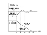
- the time chart which shows an example of the change of the bus-line voltage detection signal and motor rotation speed at the time of the deceleration adjustment operation of the motor in the motor control apparatus concerning embodiment of this invention
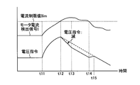
- the time chart which shows an example of the change of a motor current detection signal and a voltage command at the time of control of the motor current sent through a motor in the motor control device concerning an embodiment of the invention
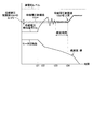
- the time chart which shows the other example of the change of a bus-bar voltage detection signal and the motor rotation speed at the time of the deceleration adjustment operation
- FIG. 1 is a configuration diagram showing a configuration of a motor control device 1 according to an embodiment of the present invention.
- FIG. 2 is a diagram illustrating an example of the hardware configuration of the components of the motor control device 1 according to the embodiment of the present invention.
- a three-phase AC power source 2 is connected to an AC input terminal, and a motor 3 that is operated with a three-phase AC voltage as a load is connected to an output terminal.
- the motor control device 1 converts the converter circuit unit 11 connected to the three-phase AC power source 2, the DC circuit unit 12 that accumulates the rectified output of the converter circuit unit 11, and converts the DC output of the DC circuit unit 12 into an AC output. And an inverter circuit unit 13 that outputs to the motor 3.
- the motor control device 1 includes a bus voltage detection unit 14 disposed at a subsequent stage of the DC circuit unit 12, a voltage control unit 15 that outputs a frequency correction value ⁇ f to control the voltage of the DC circuit unit 12, a motor 3 and a frequency command generation unit 16 that outputs a basic frequency command f1 of AC power to be output.
- the motor control device 1 also includes a voltage command calculation unit 18 that generates a voltage command V1 based on a frequency command, and a voltage command amplification unit 19 that amplifies the voltage command V1 and generates a voltage command V2.
- a voltage command generation unit 17 that generates a command
- an inverter drive unit 20 that is a drive circuit that controls the drive of the inverter circuit unit 13 based on the voltage command V2.
- the motor control device 1 includes a current detection unit 21 disposed between the inverter circuit unit 13 and the motor 3, and a current control unit 22 that generates a voltage command correction value ⁇ V for reducing the motor current. I have.
- the motor control device 1 also includes a bus voltage limit value storage memory 23 for storing the bus voltage limit value Vdc *, a subtraction connected to the bus voltage detection unit 14, the bus voltage limit value storage memory 23, and the voltage control unit 15. Connected to the voltage controller 24, the voltage controller 15, the frequency command generator 16, and the voltage command calculator 18, the voltage command amplifier 19, the inverter driver 20, and the current controller 22. And a subtractor 26.
- the motor 3 performs a power running operation and a regenerative operation.
- the regenerative power charges the DC circuit unit 12 via the inverter circuit unit 13 and raises the bus voltage.
- the converter circuit unit 11 converts the three-phase AC power fed from the AC power supply 2 through the three AC input terminals in the converter circuit unit 11 into DC power and rectifies it.
- the DC circuit unit 12 is composed of a DC voltage smoothing capacitor, smoothes and outputs the output voltage of the DC power rectified by the converter circuit unit 11, and forms a bus voltage between the positive bus P and the negative bus N To do.
- the inverter circuit unit 13 converts the bus voltage into AC power having an arbitrary magnitude and frequency by switching the bus voltage in accordance with an output voltage command whose switching element is a drive signal from the inverter drive unit 20, and from the output terminal Output to the motor 3.
- Examples of the inverter circuit unit 13 include a pulse width modulation (PWM) inverter.
- PWM pulse width modulation
- the bus voltage detector 14 detects the bus voltage between the positive bus P and the negative bus N, which is the voltage across the DC circuit 12, and outputs the detected bus voltage to the voltage controller 15 as a bus voltage detection signal Vdc.
- the voltage control unit 15 determines the voltage of the DC circuit unit 12 from the bus voltage detection signal Vdc detected by the bus voltage detection unit 14 and the bus voltage limit value Vdc * stored in the bus voltage limit value storage memory 23. In order to control, a frequency correction value ⁇ f for correcting the frequency command f1 output by the frequency command generation unit 16 is determined.
- the frequency correction value ⁇ f is a correction amount for correcting the frequency of the AC power in order to control the rotation speed of the motor 3.
- the bus voltage limit value Vdc * is a predetermined limit value of the bus voltage that is determined in advance so that the voltage of the DC circuit unit 12 does not become an overvoltage due to a voltage increase of the DC circuit unit 12 due to the regenerative power of the motor 3.
- the bus voltage limit value Vdc * is held in the bus voltage limit value storage memory 23 in advance. Further, the bus voltage limit value Vdc * can be changed as appropriate by inputting information instructing to change the bus voltage limit value Vdc * from the outside to the bus voltage limit value storage memory 23.
- a subtracter 24 receives a difference value between the bus voltage detection signal Vdc detected by the bus voltage detection unit 14 and the bus voltage limit value Vdc * stored in the bus voltage limit value storage memory 23. It is input from.
- the subtractor 24 calculates the difference value between the bus voltage detection signal Vdc and the bus voltage limit value Vdc * by performing the calculation according to the following equation (1), and outputs the difference value to the voltage controller 15.
- the voltage control unit 15 determines the frequency correction value ⁇ f based on the difference value output from the subtractor 24. Note that the voltage controller 15 may have the function of the subtractor 24. In this case, the bus voltage limit value storage memory 23 may be provided in the voltage control unit 15.
- the frequency command generator 16 outputs a frequency command f1 for controlling the rotation speed of the motor 3.
- the frequency command generation unit 16 generates a frequency command f1 and outputs the frequency command f1 to the voltage command calculation unit 18 in order to perform control for reducing the rotation speed of the motor 3 during the deceleration operation of the motor 3.
- the frequency command generation unit 16 outputs a frequency command f1 that is a command of a frequency smaller than the frequency corresponding to the current rotational speed of the motor 3 in order to perform control to reduce the rotational speed of the motor 3 during the deceleration operation.
- the frequency command generator 16 determines a frequency command f1 that is a deceleration frequency command at the time of deceleration according to a predetermined deceleration rate, based on information instructing deceleration input from the outside.
- the voltage command calculation unit 18 calculates a voltage command V1 based on the frequency command f1 output from the frequency command generation unit 16 and the frequency correction value ⁇ f output from the voltage control unit 15, and the voltage command amplification unit 19 Output to.
- the adder 25 adds the frequency command f1 output from the frequency command generation unit 16 and the frequency correction value ⁇ f output from the voltage control unit 15, and corrects the frequency command f1 with the frequency correction value ⁇ f. Command f2 is calculated. Then, the adder 25 outputs the calculated correction frequency command f2 to the voltage command calculation unit 18.
- the voltage command calculation unit 18 calculates the voltage command V1 by a preset calculation based on the correction frequency command f2, and outputs the voltage command V1 to the voltage command amplification unit 19. Note that the voltage command calculation unit 18 may have the function of the adder 25.
- the voltage command amplification unit 19 amplifies the voltage command V1 input from the voltage command calculation unit 18 with a preset amplification factor, generates a voltage command V2, and outputs the voltage command V2 to the inverter drive unit 20.
- the function of the voltage command amplification unit 19 may be performed by the voltage command calculation unit 18.
- the voltage command V ⁇ b> 2 is output to the subtractor 26, and the calculation result in the subtracter 26 is output to the inverter driving unit 20.
- the case where the subtractor 26 and the current control unit 22 are functioned will be described later.
- the case where the voltage command V2 is first input to the inverter drive unit 20 without being calculated by the subtractor 26 will be described.
- the inverter drive unit 20 calculates a voltage command that is a voltage value of AC power output from the inverter circuit unit 13 to the motor 3 in accordance with the voltage command V2 from the voltage command amplification unit 19, and the inverter circuit unit 13 as an output voltage command. Output to.
- the current detection unit 21 detects a drive current flowing from the inverter circuit unit 13 to the motor 3 and outputs the detected drive current to the current control unit 22 as a motor current detection signal I.
- the current control unit 22 generates a voltage command correction value ⁇ V for reducing the motor current by correcting the voltage command V2 based on the motor current detection signal I and the current limit value Ilim.
- the current limit value Ilim is a motor current limit reference value set to prevent motor burnout due to excessive motor current flowing through the motor 3, and is lower than the level of overcurrent that causes motor burnout. Yes, and stored in the current limit value storage memory 27 in advance. Further, the current limit value Ilim can be changed as appropriate by inputting information instructing the change of the current limit value Ilim from the outside to the current limit value storage memory 27.
- the bus voltage detection unit 14 and the current detection unit 21 can be configured using a detector that is generally used in a motor control device.
- each component other than the bus-bar voltage detection part 14 and the electric current detection part 21 among the structures of a regenerative electric power control part and a motor current control part is implement
- the processor 101 shown in FIG. 2 executes a program stored in the memory 102 for each component other than the bus voltage detector 14 and the current detector 21 in the configurations of the regenerative power controller and the motor current controller. This is realized.
- a plurality of processors and a plurality of memories may cooperate to realize the above function.
- a part of the functions other than the bus voltage detection unit 14 and the current detection unit 21 in the configuration of the regenerative power control unit and the motor current control unit is mounted as an electronic circuit, and the other parts are the processor 101 and the memory 102. You may make it implement
- FIG. 3 is a flowchart for explaining the flow of the deceleration control operation of the motor 3 in the motor control device 1 according to the present embodiment.
- the frequency command generation unit 16 sends the frequency command f1 to the voltage command calculation unit 18 in step S10. Output.
- the motor 3 is suddenly decelerated, the regenerative power from the motor 3 charges the DC circuit unit 12 via the inverter circuit unit 13 and raises the bus voltage.
- the bus voltage detection unit 14 detects the bus voltage detection signal Vdc in a predetermined cycle and outputs it to the subtracter 24 in step S20.
- step S ⁇ b> 30 the subtractor 24 calculates the difference value between the bus voltage detection signal Vdc and the bus voltage limit value Vdc * by performing the calculation according to the above formula (1), and outputs the difference value to the voltage control unit 15.
- the voltage control unit 15 Based on the difference value output from the subtractor 24, the voltage control unit 15 performs a preset operation, for example, PI control, calculates the frequency correction value ⁇ f, and outputs the frequency correction value ⁇ f to the voltage command calculation unit 18.
- the voltage control unit 15 performs control in a direction to reduce the deceleration of the rotation speed of the motor 3, that is, the rotation speed of the motor 3.
- a frequency correction value ⁇ f for performing correction for increasing the frequency command f1 is calculated.
- the time charts of the rotation speed of the motor 3 and the correction frequency command f2 have the same form. For this reason, the direction to reduce the deceleration of the rotation speed of the motor 3 is the direction to reduce the deceleration of the correction frequency command f2.
- the voltage control unit 15 controls the direction in which the deceleration of the rotation speed of the motor 3 is increased, that is, the rotation of the motor 3.
- a frequency correction value ⁇ f for performing correction to decrease the frequency command f1 is calculated.
- the time charts of the rotation speed of the motor 3 and the correction frequency command f2 have the same form. For this reason, the direction to increase the deceleration of the rotation speed of the motor 3 is the direction to increase the deceleration of the correction frequency command f2.
- the voltage control unit 15 always calculates the frequency correction value ⁇ f for each predetermined calculation cycle and outputs it to the voltage command calculation unit 18.
- step S40 the adder 25 adds the frequency command f1 output from the frequency command generation unit 16 and the frequency correction value ⁇ f output from the voltage control unit 15 to calculate a correction frequency command f2. . Then, the adder 25 outputs the calculated correction frequency command f2 to the voltage command calculation unit 18.
- the correction frequency command f2 is increased, that is, the deceleration of the rotational speed of the motor 3 is decreased, the regenerative power from the motor 3 toward the DC circuit unit 12 is reduced and the DC bus voltage is decreased.
- the correction frequency command f2 is decreased, that is, the deceleration of the rotation speed of the motor 3 is increased, the regenerative power from the motor 3 toward the DC circuit unit 12 is increased and the DC bus voltage is increased.
- the adder 25 calculates a new corrected frequency command f2 when a new frequency correction value ⁇ f is input and when a new frequency command f1 is input.
- step S50 the voltage command calculation unit 18 calculates a voltage command V1 corresponding to the correction frequency command f2 by a preset calculation based on the correction frequency command f2, and outputs the voltage command V1 to the voltage command amplification unit 19. . Further, the voltage command calculation unit 18 calculates a new voltage command V1 when a new correction frequency command f2 is input.
- step S60 the voltage command amplification unit 19 amplifies the voltage command V1 input from the voltage command calculation unit 18 with a preset amplification factor to generate the voltage command V2, and the inverter drive unit 20 Output to.
- step S ⁇ b> 70 the inverter drive unit 20 calculates an output voltage command value corresponding to the voltage command V ⁇ b> 2 input from the voltage command amplification unit 19 by a preset calculation, and outputs it to the inverter circuit unit 13. .
- step S80 based on the output voltage command value input from the inverter drive unit 20, the inverter circuit unit 13 converts the bus voltage into AC power having a frequency corresponding to the corrected frequency command f2, and from the output terminal. Output to the motor 3.
- the motor 3 is driven by AC power.
- FIG. 4 is a time chart showing an example of changes in the bus voltage detection signal and the motor rotational speed during the deceleration adjustment operation of the motor 3 in the motor control device 1 according to the present embodiment.
- the overvoltage level shown in FIG. 4 is a bus voltage value level at which the DC circuit unit 12 becomes overvoltage and the motor control device 1 is damaged.
- FIG. 4 shows the motor rotation speed
- the correction frequency command f2 is shown in the time chart of FIG. 4
- the time chart of the correction frequency command f2 has the same form as the motor rotation speed.
- the decelerations in the section from t1 to t2, the section from t2 to t3, and the section from t3 to t4 are averaged.
- deceleration control by the frequency command f1 is started at time t1.
- the motor 3 performs a regenerative operation, and the regenerative power charges the DC circuit unit 12 via the inverter circuit unit 13 to increase the bus voltage.
- the voltage control unit 15 determines that the bus voltage detection signal Vdc has transitioned to a state greater than the bus voltage limit value Vdc *, and the deceleration of the correction frequency command f2 decreases as described above. Control for reducing the deceleration of the rotational speed of the motor 3 is performed. Thereby, regenerative electric power decreases.
- the voltage control unit 15 determines that the bus voltage detection signal Vdc has transitioned to a state smaller than the bus voltage limit value Vdc *, and the deceleration of the correction frequency command f2 increases as described above. Then, the control in the direction to increase the deceleration of the rotation speed of the motor 3 is performed. Thereby, it becomes possible to decelerate the rotation speed of the motor 3 earlier than the period from the time t2 to the time t3.
- the bus voltage detection signal Vdc becomes larger than the bus voltage limit value Vdc * again, and the deceleration of the correction frequency command f2 is decreased as described above, and the rotation speed of the motor 3 is decreased. Reduction control is performed. Thereby, regenerative electric power decreases. Thereafter, at time t5, the motor 3 stops.
- the deceleration of the rotational speed of the motor 3 is corrected based on the bus voltage detection signal Vdc that is the voltage value across the DC circuit section 12. That is, when the bus voltage detection signal Vdc makes a transition larger than the bus voltage limit value Vdc *, the regenerative power can be reduced by reducing the deceleration of the rotational speed of the motor 3. Further, when the bus voltage detection signal Vdc makes a transition smaller than the bus voltage limit value Vdc *, the deceleration of the rotation speed of the motor 3 is increased to perform rapid deceleration, and the time until the motor 3 is stopped is shortened. This makes it possible to reduce the deceleration adjustment time for rapid deceleration.
- the motor control device 1 since the adjustment of the deceleration of the rotation speed of the motor 3 is automatically performed at the time of actual operation, a test is performed in advance to determine the deceleration of the rotation speed of the motor 3. It is not necessary to prepare an adjustment value, and the adjustment burden related to sudden deceleration can be reduced.
- the subtractor 26 subtracts the voltage command correction value ⁇ V input from the current control unit 22 from the voltage command V2 output from the voltage command amplification unit 19 to calculate the voltage command V3. Then, the subtractor 26 outputs the voltage command V3 to the inverter drive unit 20.
- control when control is performed to increase the motor loss and reduce the regenerative power toward the DC circuit unit 12, the control is applied to the motor 3 in order to prevent motor burnout due to excessive current flowing through the motor 3. It is necessary to suppress the motor current.
- the current detection unit 21 detects the motor current flowing from the inverter circuit unit 13 to the motor 3 at a predetermined period and sets it as the motor current detection signal I.
- a difference value between the motor current detection signal I detected by the current detector 21 and the predetermined current limit value Ilim stored in the current limit value storage memory 27 is input from the subtractor 28 to the current controller 22.
- the subtractor 28 performs a calculation according to the following equation (2), calculates a difference value between the motor current detection signal I and the current limit value Ilim, and outputs the difference value to the current control unit 22.
- the current control unit 22 Based on the difference value between the motor current detection signal I and the current limit value Ilim, the current control unit 22 performs a preset operation, for example, PI control to calculate the voltage command correction value ⁇ V.
- PI control for example, PI control to calculate the voltage command correction value ⁇ V.
- the function of the subtractor 28 may be included in the current control unit 22.
- the current limit value storage memory 27 may be provided in the current control unit 22.
- the current control unit 22 When the motor current detection signal I is larger than the current limit value Ilim, the current control unit 22 performs a preset calculation and sets the voltage command correction value ⁇ V so that the voltage command V3 becomes small. The operation of increasing is performed, and the calculated voltage command correction value ⁇ V is output to the subtractor 26.
- the subtractor 26 subtracts the voltage command correction value ⁇ V input from the current control unit 22 from the voltage command V2 input from the voltage command amplification unit 19 to calculate the voltage command V3. Then, the subtractor 26 outputs the voltage command V3 to the inverter drive unit 20.
- the inverter drive unit 20 calculates an output voltage command value corresponding to the voltage command V ⁇ b> 3 and outputs it to the inverter circuit unit 13. By outputting the output voltage command value calculated based on the voltage command V3 smaller than the voltage command V2 to the inverter circuit unit 13, the current flowing through the motor 3 can be reduced.
- the current control unit 22 When the motor current detection signal I is in a state smaller than the current limit value Ilim, the current control unit 22 performs a preset calculation and sets the voltage command correction value ⁇ V so that the voltage command V3 becomes large. The operation of decreasing is performed, and the calculated voltage command correction value ⁇ V is output to the subtractor 26. As a result, the current reduction control is released.
- the voltage command input to the inverter drive unit 20 can be reduced by performing the above-described control, the current output from the inverter circuit unit 13 to the motor 3 is reduced, and an excessive current is supplied to the motor 3. It can be prevented from flowing. As a result, it is possible to prevent motor burnout due to an excessive current flowing through the motor 3.
- the function of the subtractor 26 may be performed by the inverter driving unit 20.
- FIG. 5 shows a motor current detection signal I when controlling the motor current flowing through the motor 3 when the motor control apparatus 1 according to the present embodiment performs control to increase the number of rotations of the motor 3 and reduce the regenerative power. It is a time chart which shows an example of the change of voltage command V2, V3.
- the motor current detection signal I becomes larger than the current limit value Ilim. Then, as described above, the voltage command correction value ⁇ V is generated, and control is performed to reduce the current flowing through the motor 3 by reducing the voltage command input to the inverter drive unit 20. That is, the voltage command V3 obtained by subtracting the voltage command correction value ⁇ V output from the current control unit 22 from the voltage command V2 output from the voltage command amplification unit 19 is used as the voltage command. This prevents an excessive current from flowing through the motor 3.
- the current control unit 22 determines that the increase in the motor current detection signal I has stopped.
- the voltage command correction value ⁇ V is decreased by a predetermined small amount, and the total voltage command input to the inverter drive unit 20 is increased by a small amount, thereby performing control to increase the current flowing through the motor 3 by a small amount. Is called.
- the regenerative electric power can be increased to increase the deceleration of the rotation speed of the motor 3, and the rotation speed of the motor 3 can be decelerated earlier than the period from time t12 to time t13.
- the motor current detection signal I becomes smaller than the current limit value Ilim.
- the voltage command correction value ⁇ V decreases, and the control for reducing the voltage command input to the inverter drive unit 20 is released.
- the motor current detection signal I is the current limit value Ilim.
- FIG. 6 is a time chart showing another example of changes in the bus voltage detection signal and the motor rotational speed during the deceleration adjustment operation in the motor control device 1 according to the present embodiment. Although FIG. 6 shows the motor rotation speed, when the correction frequency command f2 is described in the time chart of FIG. 6, the time chart of the correction frequency command f2 has the same form as the motor rotation speed.
- deceleration control by the frequency command f1 is started at time t21.
- the motor 3 performs a regenerative operation, and the regenerative power charges the DC circuit unit 12 via the inverter circuit unit 13 to increase the bus voltage.
- the voltage control unit 15 determines that the bus voltage detection signal Vdc is larger than the bus voltage limit value Vdc *, and the deceleration of the correction frequency command f2 is reduced as described above. Control for reducing the deceleration of the rotational speed of 3 is performed. Thereby, regenerative electric power decreases.
- the voltage control unit 15 determines that the bus voltage detection signal Vdc is smaller than the bus voltage limit value Vdc *, the deceleration of the correction frequency command f2 increases as described above, and the motor 3 Control in the direction to increase the deceleration of the rotational speed is performed.
- the bus voltage limit value Vdc * can be increased by a predetermined amount.
- the overvoltage level is not reached even when the bus voltage detection signal Vdc exceeds the increased bus voltage limit value Vdc *, and is set small enough not to reach the overvoltage in consideration of a predetermined safety factor.
- the predetermined level range from the bus voltage limit value Vdc * is ⁇ ⁇ % of the bus voltage limit value Vdc *.
- the deceleration of the rotational speed of the motor 3 is determined based on the bus voltage detection signal Vdc that is a voltage detection value of the DC circuit unit 12. That is, when the bus voltage detection signal Vdc makes a transition larger than the bus voltage limit value Vdc *, the regenerative power can be reduced by reducing the deceleration of the rotational speed of the motor 3. Further, when the bus voltage detection signal Vdc makes a transition smaller than the bus voltage limit value Vdc *, the deceleration of the rotation speed of the motor 3 is increased to perform rapid deceleration, and the time until the motor 3 is stopped is shortened. This makes it possible to reduce the deceleration adjustment time for rapid deceleration. Therefore, according to the motor control device 1 according to the present embodiment, the motor can be rapidly decelerated more quickly while preventing damage due to the regenerative operation.
- the motor current detection signal I falls within the current limit value Ilim when the voltage command is increased at the time of motor deceleration to increase the loss of the motor 3 and suddenly decelerate. Thus, control is performed to reduce the motor current. Therefore, according to the motor control device 1 according to the present embodiment, it is possible to perform rapid deceleration while preventing motor burnout.
- the configuration described in the above embodiment shows an example of the contents of the present invention, and can be combined with another known technique, and can be combined with other configurations without departing from the gist of the present invention. It is also possible to omit or change the part.
- 1 motor control device 2 3-phase AC power supply, 3 motor, 11 converter circuit unit, 12 DC circuit unit, 13 inverter circuit unit, 14 bus voltage detection unit, 15 voltage control unit, 16 frequency command generation unit, 17 voltage command generation Unit, 18 voltage command calculation unit, 19 voltage command amplification unit, 20 inverter drive unit, 21 current detection unit, 22 current control unit, 23 bus voltage limit value storage memory, 24 subtractor, 25 adder, 26 subtractor, 27 Current limit value storage memory, 28 subtractor, 101 processor, 102 memory, f1 frequency command, f2 correction frequency command, I motor current detection signal, Ilim current limit value, N negative bus, P positive bus, V1, V2, V3 voltage Command, Vdc bus voltage detection signal, Vdc * bus voltage limit value, ⁇ f frequency correction , ⁇ V voltage command correction value.
Landscapes
- Engineering & Computer Science (AREA)
- Power Engineering (AREA)
- Control Of Ac Motors In General (AREA)
- Stopping Of Electric Motors (AREA)
Abstract
Dispositif de commande de moteur équipé : d'une unité de circuit de convertisseur (11) ; d'une unité de circuit à CC ; d'une unité de circuit onduleur (12) (13) l'unité; une ligne de bus unité de détection de tension (14); une unité de génération de commande de fréquence (16) qui délivre en sortie une commande de fréquence (f1); une unité de commande de tension (15) qui délivre en sortie une valeur de correction de fréquence (Δf) sur la base d'une ligne de bus signal de détection de tension Vdc, un module de création de commande de tension (17) qui délivre en sortie une commande de tension (V1) à partir de la commande de fréquence, ou à partir d'une commande de fréquence corrigée (f2) obtenue en corrigeant la commande de fréquence (f1) avec la valeur de correction de fréquence (Δf) ; et une unité de commande d'inverseur (20) que, sur la base d'une commande de tension (V2), délivre en sortie une commande de tension de sortie qui est une valeur de tension nécessaire pour l'entraînement d'un moteur (3). Lorsque la fréquence de la sortie de courant Alternatif au moteur (3) est abaissée et la vitesse du moteur (3) est réduite, l'unité de circuit inverseur (13) délivre en sortie au moteur (3), conformément à la commande de tension de sortie, de courant Alternatif avec une fréquence correspondant à la commande de fréquence (f1) ou la commande de fréquence corrigée (f2).
Priority Applications (3)
| Application Number | Priority Date | Filing Date | Title |
|---|---|---|---|
| PCT/JP2015/069809 WO2017006485A1 (fr) | 2015-07-09 | 2015-07-09 | Dispositif de commande de moteur |
| CN201580081493.9A CN107836077B (zh) | 2015-07-09 | 2015-07-09 | 电动机控制装置 |
| JP2016540083A JP6017100B1 (ja) | 2015-07-09 | 2015-07-09 | モータ制御装置 |
Applications Claiming Priority (1)
| Application Number | Priority Date | Filing Date | Title |
|---|---|---|---|
| PCT/JP2015/069809 WO2017006485A1 (fr) | 2015-07-09 | 2015-07-09 | Dispositif de commande de moteur |
Publications (1)
| Publication Number | Publication Date |
|---|---|
| WO2017006485A1 true WO2017006485A1 (fr) | 2017-01-12 |
Family
ID=57197596
Family Applications (1)
| Application Number | Title | Priority Date | Filing Date |
|---|---|---|---|
| PCT/JP2015/069809 Ceased WO2017006485A1 (fr) | 2015-07-09 | 2015-07-09 | Dispositif de commande de moteur |
Country Status (3)
| Country | Link |
|---|---|
| JP (1) | JP6017100B1 (fr) |
| CN (1) | CN107836077B (fr) |
| WO (1) | WO2017006485A1 (fr) |
Cited By (8)
| Publication number | Priority date | Publication date | Assignee | Title |
|---|---|---|---|---|
| CN108390551A (zh) * | 2017-02-01 | 2018-08-10 | Ls产电株式会社 | 用于控制逆变器的装置 |
| JP2018148779A (ja) * | 2017-03-06 | 2018-09-20 | エルエス産電株式会社Lsis Co., Ltd. | インバータ制御装置 |
| JP2019080419A (ja) * | 2017-10-24 | 2019-05-23 | 株式会社日立産機システム | 電力変換装置およびその制御方法 |
| CN110112941A (zh) * | 2018-02-01 | 2019-08-09 | Ls产电株式会社 | 逆变器 |
| WO2019163110A1 (fr) * | 2018-02-23 | 2019-08-29 | 三菱電機株式会社 | Dispositif d'entraînement de moteur |
| JP2019213301A (ja) * | 2018-05-31 | 2019-12-12 | 日立ジョンソンコントロールズ空調株式会社 | モータ制御装置、および、空気調和機 |
| JP2021006000A (ja) * | 2020-10-02 | 2021-01-14 | 日立ジョンソンコントロールズ空調株式会社 | モータ制御装置、および、空気調和機 |
| CN113346804A (zh) * | 2020-03-02 | 2021-09-03 | 广东威灵电机制造有限公司 | 电机控制方法、电机控制装置、电机系统和存储介质 |
Families Citing this family (3)
| Publication number | Priority date | Publication date | Assignee | Title |
|---|---|---|---|---|
| CN111130423B (zh) * | 2018-10-29 | 2022-02-11 | 广东美的环境电器制造有限公司 | 电机的驱动控制方法及装置 |
| CN111927798B (zh) * | 2020-10-12 | 2020-12-15 | 天津飞旋科技有限公司 | 一种磁悬浮分子泵降速控制方法和装置 |
| CN113411033A (zh) * | 2021-07-15 | 2021-09-17 | 中冶赛迪工程技术股份有限公司 | 一种变频器带电机负载输入过电压判别方法 |
Citations (5)
| Publication number | Priority date | Publication date | Assignee | Title |
|---|---|---|---|---|
| JPH0837796A (ja) * | 1994-07-25 | 1996-02-06 | Toshiba Corp | インバータ装置 |
| JPH099661A (ja) * | 1995-06-20 | 1997-01-10 | Yaskawa Electric Corp | インバータ駆動誘導電動機の制動方法 |
| JP2005295614A (ja) * | 2004-03-31 | 2005-10-20 | Yaskawa Electric Corp | 交流電動機の減速方法及びインバータ装置 |
| JP2007221864A (ja) * | 2006-02-14 | 2007-08-30 | Yaskawa Electric Corp | 交流電動機のインバータ制御装置 |
| JP2012165582A (ja) * | 2011-02-08 | 2012-08-30 | Sharp Corp | モータ制御装置 |
Family Cites Families (7)
| Publication number | Priority date | Publication date | Assignee | Title |
|---|---|---|---|---|
| JPH05344789A (ja) * | 1992-06-10 | 1993-12-24 | Toshiba Corp | インバータ制御方法 |
| JP3622410B2 (ja) * | 1997-03-12 | 2005-02-23 | 株式会社安川電機 | インバータによる電動機の制御方法 |
| CN1838522A (zh) * | 2005-03-23 | 2006-09-27 | 台达电子工业股份有限公司 | 马达运转状态的控制方法 |
| US8030861B2 (en) * | 2006-07-04 | 2011-10-04 | Nxp B.V. | Method for controlling a deceleration process of a DC motor and controller |
| JP2008154335A (ja) * | 2006-12-15 | 2008-07-03 | Yaskawa Electric Corp | インバータ装置と過電圧抑制方法 |
| WO2012086674A1 (fr) * | 2010-12-22 | 2012-06-28 | 富士電機株式会社 | Appareil de conversion d'énergie |
| JP5753770B2 (ja) * | 2011-03-30 | 2015-07-22 | 株式会社日立産機システム | 電力変換装置 |
-
2015
- 2015-07-09 CN CN201580081493.9A patent/CN107836077B/zh active Active
- 2015-07-09 WO PCT/JP2015/069809 patent/WO2017006485A1/fr not_active Ceased
- 2015-07-09 JP JP2016540083A patent/JP6017100B1/ja active Active
Patent Citations (5)
| Publication number | Priority date | Publication date | Assignee | Title |
|---|---|---|---|---|
| JPH0837796A (ja) * | 1994-07-25 | 1996-02-06 | Toshiba Corp | インバータ装置 |
| JPH099661A (ja) * | 1995-06-20 | 1997-01-10 | Yaskawa Electric Corp | インバータ駆動誘導電動機の制動方法 |
| JP2005295614A (ja) * | 2004-03-31 | 2005-10-20 | Yaskawa Electric Corp | 交流電動機の減速方法及びインバータ装置 |
| JP2007221864A (ja) * | 2006-02-14 | 2007-08-30 | Yaskawa Electric Corp | 交流電動機のインバータ制御装置 |
| JP2012165582A (ja) * | 2011-02-08 | 2012-08-30 | Sharp Corp | モータ制御装置 |
Cited By (14)
| Publication number | Priority date | Publication date | Assignee | Title |
|---|---|---|---|---|
| CN108390551A (zh) * | 2017-02-01 | 2018-08-10 | Ls产电株式会社 | 用于控制逆变器的装置 |
| CN108390551B (zh) * | 2017-02-01 | 2020-09-15 | Ls产电株式会社 | 用于控制逆变器的装置 |
| US10411630B2 (en) | 2017-03-06 | 2019-09-10 | Lsis Co., Ltd. | Inverter control apparatus |
| JP2018148779A (ja) * | 2017-03-06 | 2018-09-20 | エルエス産電株式会社Lsis Co., Ltd. | インバータ制御装置 |
| JP2019080419A (ja) * | 2017-10-24 | 2019-05-23 | 株式会社日立産機システム | 電力変換装置およびその制御方法 |
| CN110112941A (zh) * | 2018-02-01 | 2019-08-09 | Ls产电株式会社 | 逆变器 |
| CN110112941B (zh) * | 2018-02-01 | 2021-02-26 | Ls产电株式会社 | 逆变器 |
| WO2019163110A1 (fr) * | 2018-02-23 | 2019-08-29 | 三菱電機株式会社 | Dispositif d'entraînement de moteur |
| WO2019163729A1 (fr) * | 2018-02-23 | 2019-08-29 | 三菱電機株式会社 | Appareil et système d'entraînement de moteur |
| JPWO2019163729A1 (ja) * | 2018-02-23 | 2020-02-27 | 三菱電機株式会社 | モータ駆動装置、及びモータ駆動システム |
| JP2019213301A (ja) * | 2018-05-31 | 2019-12-12 | 日立ジョンソンコントロールズ空調株式会社 | モータ制御装置、および、空気調和機 |
| CN113346804A (zh) * | 2020-03-02 | 2021-09-03 | 广东威灵电机制造有限公司 | 电机控制方法、电机控制装置、电机系统和存储介质 |
| JP2021006000A (ja) * | 2020-10-02 | 2021-01-14 | 日立ジョンソンコントロールズ空調株式会社 | モータ制御装置、および、空気調和機 |
| JP7153697B2 (ja) | 2020-10-02 | 2022-10-14 | 日立ジョンソンコントロールズ空調株式会社 | モータ制御装置、および、空気調和機 |
Also Published As
| Publication number | Publication date |
|---|---|
| CN107836077B (zh) | 2020-07-07 |
| JPWO2017006485A1 (ja) | 2017-07-13 |
| CN107836077A (zh) | 2018-03-23 |
| JP6017100B1 (ja) | 2016-10-26 |
Similar Documents
| Publication | Publication Date | Title |
|---|---|---|
| JP6017100B1 (ja) | モータ制御装置 | |
| TWI243532B (en) | Inverter device and current limiting method therefor | |
| JP4461877B2 (ja) | インバータ装置 | |
| JP5954313B2 (ja) | モータ制御システム、制御装置及び制御方法 | |
| JP5134691B2 (ja) | 自励式無効電力補償装置 | |
| JP6448757B2 (ja) | インバータ制御方法 | |
| JPWO2006004037A1 (ja) | インバータ装置および交流電動機の減速方法 | |
| JP6258806B2 (ja) | 系統連系用電力変換装置 | |
| JP5932136B2 (ja) | モータ制御装置 | |
| JP7029368B2 (ja) | 同期電動機制御装置 | |
| WO2016035434A1 (fr) | Dispositif d'entraînement de moteur | |
| JP2001037236A (ja) | 電力変換装置の電圧制御装置 | |
| CN114499223B (zh) | 电力转换装置、电力转换控制方法以及计算机可读记录介质 | |
| KR100817116B1 (ko) | 인버터 시스템의 관성부하 억제 장치 및 그 방법 | |
| JP6854193B2 (ja) | パワーコントロールユニット | |
| KR101437202B1 (ko) | 복전시 인버터의 전압보상지령 보정방법 및 그 방법을 이용한 인버터 | |
| JP7515728B1 (ja) | 制御装置、電力変換装置及び制御方法 | |
| JP6669434B2 (ja) | 電力変換装置 | |
| JP4831530B2 (ja) | 交流電動機のインバータ制御装置とその制御方法 | |
| JP6740794B2 (ja) | 電力変換装置の過電流抑制装置 | |
| TWI401863B (zh) | 馬達再生電壓抑制之裝置及其方法 | |
| JP6958387B2 (ja) | 直流電源装置および直流電源装置の制御方法 | |
| JP5099873B2 (ja) | インバータ電流制限制御 | |
| JP6508782B2 (ja) | 電力変換装置および直流電圧制御装置 | |
| WO2018127960A1 (fr) | Dispositif de conversion d'énergie |
Legal Events
| Date | Code | Title | Description |
|---|---|---|---|
| ENP | Entry into the national phase |
Ref document number: 2016540083 Country of ref document: JP Kind code of ref document: A |
|
| 121 | Ep: the epo has been informed by wipo that ep was designated in this application |
Ref document number: 15897746 Country of ref document: EP Kind code of ref document: A1 |
|
| NENP | Non-entry into the national phase |
Ref country code: DE |
|
| 122 | Ep: pct application non-entry in european phase |
Ref document number: 15897746 Country of ref document: EP Kind code of ref document: A1 |