WO2017006487A1 - Bobine d'allumage pour dispositif d'allumage pour moteur à combustion interne - Google Patents
Bobine d'allumage pour dispositif d'allumage pour moteur à combustion interne Download PDFInfo
- Publication number
- WO2017006487A1 WO2017006487A1 PCT/JP2015/070339 JP2015070339W WO2017006487A1 WO 2017006487 A1 WO2017006487 A1 WO 2017006487A1 JP 2015070339 W JP2015070339 W JP 2015070339W WO 2017006487 A1 WO2017006487 A1 WO 2017006487A1
- Authority
- WO
- WIPO (PCT)
- Prior art keywords
- primary coil
- coil
- main
- sub
- bobbin
- Prior art date
- Legal status (The legal status is an assumption and is not a legal conclusion. Google has not performed a legal analysis and makes no representation as to the accuracy of the status listed.)
- Ceased
Links
Images

Classifications
-
- F—MECHANICAL ENGINEERING; LIGHTING; HEATING; WEAPONS; BLASTING
- F02—COMBUSTION ENGINES; HOT-GAS OR COMBUSTION-PRODUCT ENGINE PLANTS
- F02P—IGNITION, OTHER THAN COMPRESSION IGNITION, FOR INTERNAL-COMBUSTION ENGINES; TESTING OF IGNITION TIMING IN COMPRESSION-IGNITION ENGINES
- F02P15/00—Electric spark ignition having characteristics not provided for in, or of interest apart from, groups F02P1/00 - F02P13/00 and combined with layout of ignition circuits
- F02P15/08—Electric spark ignition having characteristics not provided for in, or of interest apart from, groups F02P1/00 - F02P13/00 and combined with layout of ignition circuits having multiple-spark ignition, i.e. ignition occurring simultaneously at different places in one engine cylinder or in two or more separate engine cylinders
-
- F—MECHANICAL ENGINEERING; LIGHTING; HEATING; WEAPONS; BLASTING
- F02—COMBUSTION ENGINES; HOT-GAS OR COMBUSTION-PRODUCT ENGINE PLANTS
- F02P—IGNITION, OTHER THAN COMPRESSION IGNITION, FOR INTERNAL-COMBUSTION ENGINES; TESTING OF IGNITION TIMING IN COMPRESSION-IGNITION ENGINES
- F02P15/00—Electric spark ignition having characteristics not provided for in, or of interest apart from, groups F02P1/00 - F02P13/00 and combined with layout of ignition circuits
- F02P15/10—Electric spark ignition having characteristics not provided for in, or of interest apart from, groups F02P1/00 - F02P13/00 and combined with layout of ignition circuits having continuous electric sparks
Definitions
- the present invention relates to an ignition coil of an ignition device for an internal combustion engine mounted on a motor vehicle.
- the ignition coil employs a primary coil structure that can increase the discharge energy generated on the secondary side of the ignition coil in a superimposed manner and obtain good discharge characteristics.
- Patent Document 1 As an internal combustion engine mounted on a vehicle, a direct injection engine or a high EGR engine is adopted to improve fuel efficiency. However, since these engines are not very ignitable, a high energy type ignition device is required. In view of this, a phase discharge type ignition device has been proposed in which the output of another ignition coil is additionally superimposed on the secondary output of the ignition coil generated by the classic current interruption principle (Patent Document 1).
- the primary current of the main ignition coil is cut off, and a high voltage of several kV generated on the secondary side thereof causes dielectric breakdown in the discharge gap of the spark plug, thereby After starting the discharge current from the secondary side, the primary current of the auxiliary ignition coil connected in parallel with the main ignition coil is cut off, and a DC voltage of several kV generated on the secondary side is additionally superimposed.
- a large discharge energy can be applied to the spark plug for a relatively long time, so that the ignitability of the fuel is improved and the fuel consumption is also improved.
- the ignition device described in Patent Document 1 has a problem as an ignition control technique in addition to these structural problems. That is, in the ignition device described in Patent Document 1, since it is necessary to increase the ignition phase of the two ignition coils in order to increase the discharge time of the ignition plug, the discharge time of the ignition plug is increased. In addition, the time for accumulating sufficient energy in the two ignition coils also becomes longer, so the combustion rate cannot be increased.
- the ignition device described in Patent Document 1 can stabilize the engine output by maintaining stable combustion, but the ignition cannot be increased so that a high output can be obtained at a necessary timing. Problems in control technology arise. Accordingly, the present invention provides an ignition coil that is suitable for an internal combustion engine ignition device capable of realizing ignition control capable of maintaining stable combustion without increasing the energization time of the primary coil, and can suppress an increase in size and cost. The purpose is to provide.
- the invention according to claim 1 is directed to a main primary coil in which an energized magnetic flux in the forward direction is generated by energization from a DC power supply, and a reverse interrupted magnetic flux is generated by interrupting the current;
- a sub-primary coil in which an additional magnetic flux in the same direction as the breaking magnetic flux is generated by energization from a power source, a ferromagnetic iron core that generates magnetic induction by the action of the magnetic field of the main primary coil and the sub-primary coil, and each cylinder of the internal combustion engine
- a secondary coil that generates discharge energy when one end side is connected to the spark plug provided on the main plug and the magnetic flux generated in each of the primary primary coil and the secondary primary coil acts via the iron core.
- the invention according to claim 2 is the ignition coil of the ignition device for an internal combustion engine according to claim 1, wherein the main primary coil and the secondary primary coil are for a primary coil in which a center iron core passes through an inner space. It is characterized in that it is provided in a laminated form on the bobbin body via insulating means.
- a magnet wire is wound around a body portion of the bobbin for the primary coil to form a main primary coil, By covering the outer surface of the main primary coil with an insulating sheet, it becomes an insulating means, and by forming a secondary primary coil by winding a magnet wire from the outer surface of the insulating sheet, the secondary primary coil is formed on the outer layer of the primary primary coil. A coil is formed.
- a magnet wire is wound around the body of the bobbin for the primary coil to form a secondary primary coil,
- an insulating sheet as an insulating means, and forming the main primary coil by winding a magnet wire from the outer surface of the insulating means, the main primary coil is formed on the outer layer of the sub-primary coil. A coil is formed.
- the invention according to claim 5 is the ignition coil of the internal combustion engine ignition device according to any one of claims 2 to 4, wherein the energization side terminal of the main primary coil and the auxiliary primary coil The current-carrying side terminal is pulled out from the same side of the primary coil bobbin, and the winding direction of the primary primary coil and the winding direction of the secondary primary coil are reversed, so that the breaking magnetic flux and the additional magnetic flux are in the same direction. It is characterized by doing so.
- the invention according to claim 6 is the ignition coil of the ignition device for an internal combustion engine according to any one of claims 2 to 4, wherein the winding direction of the main primary coil and the secondary primary coil are By making the winding direction the same and pulling out the energization side terminal of the main primary coil and the energization side terminal of the sub primary coil from different sides of the bobbin for the primary coil, the breaking magnetic flux and the additional magnetic flux are in the same direction. It is characterized by doing so.
- the invention according to claim 7 is the ignition coil of the ignition device for an internal combustion engine according to claim 1, wherein the main primary coil and the secondary primary coil are for a primary coil in which a center iron core passes through an inner space.
- the bobbin body is provided in parallel at different positions on the body of the bobbin via an insulating means.
- the invention according to claim 8 is the ignition coil of the internal combustion engine ignition device according to claim 7, wherein the primary coil bobbin is divided into a main primary coil bobbin and a sub primary coil bobbin,
- the main primary coil is configured by winding a magnet wire around the body of the main primary coil bobbin
- the sub primary coil is configured by winding the magnet wire around the body of the sub primary coil bobbin
- the main primary coil and the secondary primary coil are arranged in parallel in the longitudinal direction of the center core by passing the center core through the inner space of each of the primary primary coil bobbin and the secondary primary coil bobbin, and the primary primary coil bobbin
- each end of the secondary primary coil bobbin is an insulating means for separating the primary primary coil and the secondary primary coil.
- the invention according to claim 9 is the ignition coil of the internal combustion engine ignition device according to claim 8, wherein the main primary coil bobbin and the sub primary coil bobbin are respectively inserted into the center iron core.
- the primary coil and the sub primary coil are wound in opposite directions, and the energization side terminal of the main primary coil and the energization side terminal of the sub primary coil are on the same side of the main primary coil bobbin and the sub primary coil bobbin. It is characterized in that the breaking magnetic flux and the additional magnetic flux are in the same direction.
- the main primary coil bobbin and the sub primary coil bobbin are respectively inserted into the center iron core.
- the primary coil and the secondary primary coil are wound in the same direction, and the energization side terminal of the main primary coil and the energization side terminal of the sub primary coil are opposite to the main primary coil bobbin and the sub primary coil bobbin, respectively. By drawing out from the side, the breaking magnetic flux and the additional magnetic flux are in the same direction.
- the ignition coil of the ignition device for an internal combustion engine provides the secondary primary coil does not significantly increase the size of the ignition coil, and is effective in suppressing cost increase.
- ignition control is performed so that the secondary primary coil is energized for a predetermined overlap time after the shut-off timing at which the energization to the main primary coil is interrupted by the internal combustion engine ignition device, the energization time to the primary coil is lengthened.
- the discharge energy generated in the secondary coil can be increased in a superimposed manner to maintain stable combustion.
- FIG. 1 is an explanatory diagram of a configuration of an ignition coil of an internal combustion engine ignition device according to the present invention.
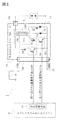
- FIG. 2 is a schematic configuration diagram of an internal combustion engine ignition device in which the ignition coil shown in FIG. 1 is mounted.
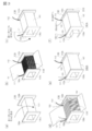
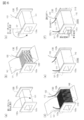
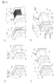
- FIG. 3 is an assembly process diagram showing an outline of the process of assembling the primary coil of the first configuration example applicable to the ignition coil of the internal combustion engine ignition device according to the present invention.
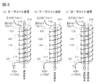
- FIG. 4 is an explanatory diagram showing changes in magnetic flux in the primary coil of the first configuration example shown in FIG.
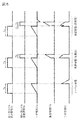
- FIG. 5 is a discharge waveform diagram in the internal combustion engine ignition device of FIG.
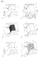
- FIG. 6 is an assembly process diagram showing an outline of the process of assembling the primary coil of the second configuration example applicable to the ignition coil of the internal combustion engine ignition device according to the present invention.
- FIG. 7 is an assembly process diagram showing an outline of the process of assembling the primary coil of the third configuration example applicable to the ignition coil of the internal combustion engine ignition device according to the present invention.
- (1a), (1b) and (1c) of FIG. 8 are assembly process diagrams showing an outline of a process of assembling a primary coil of a fourth configuration example applicable to the ignition coil of the internal combustion engine ignition device according to the present invention.
- (2a), (2b), (2c) are assembly process diagrams showing an outline of a process of assembling the primary coil of the fifth configuration example applicable to the ignition coil of the internal combustion engine ignition device according to the present invention.
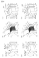
- FIG. 9 is an assembly process diagram showing an outline of the process of assembling the primary coil of the sixth configuration example applicable to the ignition coil of the internal combustion engine ignition device according to the present invention.
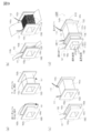
- FIG. 10 is an assembly process diagram showing an outline of the process of assembling the primary coil of the seventh configuration example applicable to the ignition coil of the internal combustion engine ignition device according to the present invention.
- FIG. 1A shows the appearance of the ignition coil 10
- FIG. 1B shows the inside by cutting only the coil portion.
- the ignition coil 10 includes at least a primary coil 100 that generates a magnetic field when energized and interrupted, a ferromagnetic iron core 300 that generates magnetic induction by the action of the magnetic field of the primary coil, and a magnetic field that is generated in the primary coil generates iron core 300.
- a secondary coil 200 that generates discharge energy.
- the primary coil 100 includes a main primary coil 110 and a sub primary coil 120.
- the main primary coil 110 is configured by winding a magnet wire such as an enamel wire around the primary coil bobbin 130 (for example, 114 turns), and an inner layer insulating sheet 141 is mounted on the outer surface of the main primary coil 110.
- a sub primary coil 120 is formed by winding a magnet wire (for example, 20 to 30 turns) around the outside of the insulating sheet 141.
- An outer insulating sheet 142 is attached to the outer surface of the sub primary coil 120.
- the secondary coil 200 is configured by winding a magnet wire (for example, 9348 turns) around a secondary coil bobbin 210, and the primary coil bobbin is placed in an inner space 210a of the secondary coil bobbin 210. 130 is accommodated.
- the iron core 300 includes a center iron core 310 inserted into the inner space 130a of the primary coil bobbin 130 and an annular iron core 320 disposed outside the secondary coil bobbin 210.
- a permanent magnet 330 is provided between the center iron core 310 and the annular iron core 320 to apply a magnetic reverse bias to the iron core 300.
- the ignition coil 10 configured as described above can individually energize / shut off the main primary coil 110 and energize / shut off the sub-primary coil 120 individually. As a result, the generated magnetic field can be appropriately set according to the winding direction and energization direction of the main primary coil 110 and the sub primary coil 120.
- the internal combustion engine ignition device 1 includes an ignition coil unit 11 that generates a discharge spark in one spark plug 2 provided for each cylinder of the internal combustion engine, and an ignition control means 3a that controls the operation of the ignition coil unit 11. Is done.
- the ignition control means 3a shown in the present embodiment is included in the engine control unit 3 that is an internal combustion engine control device that comprehensively controls the internal combustion engine of the automobile, and an ignition signal from the engine control unit 3 (later As will be described in detail, the operation of the ignition coil unit 11 is appropriately controlled.
- the ignition coil unit 11 is, for example, a unit in which an ignition coil 10, a main IGBT (Insulated Gate Bipolar Transistor) 12a, and a sub-IGBT 12b are housed in a case 13 having a required shape.
- a high voltage terminal 13a and a connector 13b are provided at appropriate positions of the case 13, and the spark plug 2 is connected through the high voltage terminal 13a, and the DC power source 4 such as the engine control unit 3 and the vehicle battery is connected through the connector 13b.
- the ignition coil 10 causes the magnetic flux generated in the main primary coil 110 and the sub primary coil 120 to act on the secondary coil 200 by energization / cutoff control from the engine control unit 3.
- main primary coil 110 and the sub primary coil 120 are connected to a DC power supply 4 such as a vehicle battery, and a common power supply voltage VB + (for example, +12 V) is applied.
- VB + for example, +12 V
- the other end of main primary coil 110 is connected to ground point GND via main IGBT 12a.
- the main IGBT 12a is a semiconductor element capable of high-power high-speed switching, and switches energization / cut-off to the main primary coil 110 based on the main primary coil ignition signal Sa from the ignition control means 3a.
- the other end of the secondary primary coil 120 is connected to the ground point GND via the secondary IGBT 12b.
- the sub-IGBT 12b is a semiconductor element capable of high-power high-speed switching, and switches energization / cut-off to the sub-primary coil 120 based on the sub-primary coil superimposed signal Sb from the ignition control means 3a.
- the main primary coil 110 and the sub primary coil 120 need to have different winding directions or feeding positions so that the direction of magnetic flux generated when energized from the DC power supply 4 is reversed.
- a primary coil 100A that is a first configuration example of a primary coil that satisfies this condition will be described with reference to FIG.
- the primary coil bobbin 130 has, for example, a structure in which a first flange portion 132a and a second flange portion 132b are provided at both ends of a substantially square columnar body portion 131, respectively, and a magnet wire is wound around the outer surface of the body portion 131. Is done.
- the winding direction for forming the primary coil is referred to as right-handed winding or left-handed winding for the sake of convenience with reference to the direction from the first collar 132a to the second collar 132b.
- the main primary coil 110 is formed by winding a magnet wire around the primary coil bobbin 130 right-handed a required number of times (for example, 114 turns) (see FIGS. 3A and 3B).
- the first flange 132a side is referred to as a winding start side lead wire 111
- the second flange portion 132b side is referred to as a winding end side lead wire 112.
- the outer surface of the main primary coil 110 is covered with an inner insulating sheet 141 as an insulating means, and the magnet wire is left-hand-wrapped from the outer surface by a required number of times (for example, 20 to 30 turns), whereby the sub primary coil 120 is wound. (See FIGS. 3B, 3C, and 3D).
- the winding start side lead wire 121 is drawn out to the first flange portion 132a side of the sub primary coil 120, and the winding end side lead wire 122 is drawn out to the second flange portion 132b side.
- the outer coil insulation sheet 142 is attached to the outer surface of the sub-primary coil 120 to form the primary coil 100A.
- the center iron core 310 is inserted through the inner space 130a (see FIGS. 3E and 3F).
- the winding start side lead wire 111 of the main primary coil 110 and the winding start side lead wire 121 of the sub primary coil 120 are connected to a common DC power source (VB +), and the main primary coil 110 is connected.
- the winding end side lead wire 112 of the secondary primary coil 120 is connected to the main IGBT 12a, and the winding end side lead wire 122 of the secondary primary coil 120 is connected to the secondary IGBT 12b.
- the primary coil 100A configured as described above, when the main primary coil 110 is energized, when the main primary coil 110 is de-energized, the sub-primary coil 120 is energized following the de-energization of the main primary coil 110.
- FIG. 4 schematically shows the generated magnetic flux.
- the number of turns of the sub primary coil 120 is set so that the voltage generated in the sub primary coil 120 due to a change in magnetic flux when the energization of the main primary coil 110 is cut off becomes smaller than the power supply voltage (for example, +12 V). It is necessary to keep. This is because, when the voltage generated in the secondary primary coil 120 when the energization to the primary primary coil 110 is cut off is larger than the voltage of the DC power supply 4, the superimposed magnetic flux is generated even if the secondary IGBT 12b is turned on. This is because the superposed current I1b cannot flow.
- the power supply voltage for example, +12 V
- a bypass line 14 is provided in parallel with the main IGBT 12a, and a rectifier 15 (for example, a cathode is connected to the collector side of the main IGBT 12a in the forward direction from the ground point side of the bypass line 14 toward the ignition coil 10 side.
- a diode having an anode connected to the emitter side of the IGBT 12a is provided.
- the ignition control means 3a performs normal discharge control in an operating situation in which appropriate discharge characteristics are obtained only by the main primary coil 110 without adding a superimposed magnetic flux to the interrupting magnetic flux.
- the signal level of the main primary coil ignition signal Sa is changed from L to H at an appropriate timing of the discharge cycle, the main IGBT 12a is turned on, and the primary current I1a starts to flow.
- the signal level of the main primary coil ignition signal Sa is changed from H to L, the main IGBT 12a is turned off, the primary current I1a is cut off, and the secondary coil 200 side is turned on.
- a current I2 is supplied.
- the signal level of the sub primary coil superimposed signal Sb is maintained at L, the sub IGBT 12b remains off, and the superimposed current I1b does not flow through the sub primary coil 120, so that the superimposed magnetic flux acts on the secondary coil 200. There is nothing.
- the ignition control means 3a performs high current type superimposed discharge control.
- the signal level of the main primary coil ignition signal Sa is changed from H to L at the timing when the primary current energization time Ta has passed, and the main IGBT 12a is turned off.
- the signal level of the sub primary coil superimposed signal Sb is changed from L to H, the sub IGBT 12b is turned on, and the primary current I1b is supplied.
- the superimposed magnetic flux generated by the energization of the sub primary coil 120 is added at the timing immediately after the start of the discharge at which the interruption magnetic flux generated by the energization interruption of the main primary coil 110 is maximized, and the initial secondary current I2 is added. Becomes a high current.
- the signal level of the sub primary coil superimposed signal Sb is changed from H to L at the timing when the superposed current energizing time Tb determined taking into account the time necessary for discharging the spark plug 2 has elapsed, and the sub IGBT 12b is turned off.
- the superimposed current I1b is cut off.
- the ignition control means 3a performs long discharge type superimposed discharge control.
- the primary current energization time Ta elapses, the main IGBT 12a is turned off, the primary current I1a is cut off, and the secondary current I2 is supplied to the secondary coil 200 side.
- the signal level of the sub primary coil superimposed signal Sb remains L. Thereafter, the signal level of the sub primary coil superposition signal Sb is changed from L to H at the timing when the superposition start delay time ⁇ t determined in consideration of the time during which the secondary current I2 is maintained at a predetermined value or more.
- the secondary IGBT 12b is turned on, and the primary current I1b is supplied.
- the time until the secondary current I2 becomes higher again and the secondary current I2 becomes lower than a predetermined value (energy required for discharging the spark plug 2 is lost) can be extended.
- the discharge period can be kept long.
- the signal level of the sub primary coil superimposed signal Sb is changed from H to L at the timing when the superposed current energizing time Tb determined taking into account the time necessary for discharging the spark plug 2 has elapsed, and the sub IGBT 12b is turned off.
- the superimposed current I1b is cut off.
- the engine control unit 3 having the function of the ignition control means 3a is configured so that the sub-primary coil 120 is The energization start timing and energization time are determined, and the secondary primary coil superimposed signal Sb is generated accordingly to turn on / off the secondary IGBT 12b, so that the cutoff magnetic flux by the main primary coil 110 and the superimposed magnetic flux by the secondary primary coil 120 are changed. It is generated at an appropriate timing, and the ignition control that achieves a discharge characteristic suitable for the driving situation at that time is realized.
- the information used for determining the operating condition may be any information as long as it is information related to the combustion of the cylinder, such as the engine speed, the secondary current value, the temperature of the ignition coil 10, and the like.
- the ignition coil 10 having a structure suitable for the above-described internal combustion engine ignition device 1 uses the primary coil 100 that can be configured simply by increasing the number of steps of providing the sub-primary coil 120 on the outer layer of the main primary coil 110. There is no significant complication and cost increase can be suppressed.
- the sub primary coil 120 provided on the outer layer of the main primary coil 110 may be about several tens of turns (for example, 10 to 30 turns), the provision of the sub primary coil 120 significantly increases the size of the ignition coil 10 itself. There is nothing.
- the primary coil 100 can be produced by diverting the existing primary coil bobbin 130, compatibility with the secondary coil 200 and the iron core 300 can be maintained, which is more effective in suppressing cost increase.
- the main primary coil 110 and the sub primary coil 120 are both fed from the winding start side lead wires 111 and 121 on the first flange 132a side, there is an advantage that connection to the power supply terminal becomes easy.
- the illustrated primary coil bobbin 130 is shown in a simplified manner, a power connection terminal to which the winding start side lead wires 111 and 121 are soldered and a main IGBT connection to which the winding end side lead wire 112 is soldered are shown.
- the ignition coil 10 according to the present invention has an advantage that the degree of freedom in design is high.
- the main primary coil 110 is wound on the inner layer with right-handed winding
- the sub-primary coil 120 is wound on the outer layer with left-handed winding.
- the structure is limited to such a structure. is not.
- the sub-primary coil 120 is wound in the right-handed inner layer, and the main primary coil 110 is wound in the left-handed outer layer.
- the winding start side lead wire 121 of the sub primary coil 120 and the winding start side lead wire 111 of the main primary coil 110 are connected to a common DC power supply (VB +), and the winding end side lead of the sub primary coil 120 is connected.
- the wire 122 is connected to the secondary IGBT 12b, and the winding end side lead wire 112 of the main primary coil 110 is connected to the main IGBT 12a. That is, in the primary coil 100B, as shown in FIG.
- the ignition coil 10 using the primary coil 100 ⁇ / b> B of the second configuration example is applied to the internal combustion engine ignition device 1, it is possible to realize an ignition control that can obtain discharge characteristics suitable for the operation state at that time.
- the provision of the sub primary coil 120 does not significantly increase the size of the ignition coil 10 itself, and is effective in suppressing an increase in cost.
- the primary coil 100A of the first configuration example and the primary coil 100B of the second configuration example described above are different in the winding directions of the primary primary coil 110 and the secondary primary coil 120, and lead wires on the same side are connected to direct current. Although connected to the power supply (VB +), it is not limited to this structure.
- both the inner primary primary coil 110 and the outer secondary primary coil 120 are right-handed.
- the winding start side lead wire 111 of the main primary coil 110 and the winding end side lead wire 122 of the sub primary coil 120 are connected to a common DC power source (VB +), and the winding start side of the sub primary coil 120 is connected.
- the lead wire 121 is connected to the sub-IGBT 12b, and the winding end side lead wire 112 of the main primary coil 110 is connected to the main IGBT 12a. That is, in the primary coil 100C, as shown in FIG.
- the main primary coil 110 is fed from the first flange 132a side, and the sub-primary coil 120 is fed from the second flange 132b side.
- the direction of the current flowing through the main primary coil 110 (rightward from the first collar 132a to the second collar 132b) and the direction of the current flowing through the sub-primary coil 120 (from the second collar 132b to the first collar 132a).
- the direction of the interrupting magnetic flux generated when the current to the main primary coil 110 is interrupted (the direction from the second flange 132b to the first flange 132a) is generated in the sub-primary coil 120.
- the direction of the superimposed magnetic flux can be the same.
- the ignition coil 10 using the primary coil 100 ⁇ / b> C of the third configuration example is applied to the internal combustion engine ignition device 1, ignition control capable of obtaining discharge characteristics suitable for the operation state at that time can be realized.
- the provision of the sub-primary coil 120 does not significantly increase the size of the ignition coil 10 itself, and is effective in suppressing an increase in cost.
- the winding directions of the main primary coil 110 and the sub primary coil 120 are the same, even when the primary coil 100C is manufactured using an automatic winding machine having only a unidirectional winding function, the winding is efficiently performed. Can work.
- Each of the primary coils 100A to 100C of the first to third configuration examples described above has a laminated structure in which the main primary coil 110 and the sub primary coil 120 are outer layers or inner layers, but is not limited to this structure.
- the main primary coil 110 and the sub primary coil 120 are arranged in parallel at different positions on the body 131 ′ of the primary coil bobbin 130 ′. It is provided in the shape.
- the primary coil bobbin 130 ′ used in the primary coil 100 ⁇ / b> D has a body portion around which a magnet wire is wound by providing a partition flange portion 132 c between the first flange portion 132 a and the second flange portion 132 b which are both ends thereof.
- 131 ' is divided into a main primary coil winding region 131a and a sub primary coil winding region 131b.
- the main primary coil 110 is comprised by winding a magnet wire in the left-handed winding direction toward the division collar part 132c from the 1st collar part 132a, and the sub primary coil winding area
- the secondary primary coil 120 is configured by winding a magnet wire in a left-handed winding direction from the partition hook 132c toward the second hook 132b.
- the primary primary coil 110 and the secondary primary coil 120 provided in parallel via the partition ribs 132b functioning as the insulating means are provided with the outer layer insulating sheets 143a and 143b on the outer surfaces thereof to become the primary coil 100D.
- the winding start side lead wire 111 of the primary primary coil 110 is connected to the primary IGBT 12a, and the primary primary coil
- the winding end side lead wire 112 of 110 and the winding start side lead wire 121 of the sub primary coil 120 are connected to a common DC power supply (VB +), and the winding end side lead wire 122 of the sub primary coil 120 is connected to the sub IGBT 12b. That is, in the primary coil 100D, as shown in FIG.
- the primary primary coil 110 and the secondary primary coil 120 are respectively on different sides (for the primary primary coil 110, the winding end side, and for the secondary primary coil 120, winding is performed.
- the direction of the interrupting magnetic flux generated when the current to the main primary coil 110 is interrupted can be the same as the direction of the superimposed magnetic flux generated in the secondary primary coil 120.
- region 131b is provided in the 1st collar part 132a side
- region 131a is provided in the 2nd collar part 132b side
- the main primary coil 110 and the sub primary coil 120 are division collar parts.
- the ignition control capable of obtaining discharge characteristics suitable for the driving situation at that time is realized. it can.
- the provision of the sub primary coil 120 does not significantly increase the size of the ignition coil 10 itself, and is effective in suppressing an increase in cost.
- the winding directions of the main primary coil 110 and the sub primary coil 120 are the same, even when the primary coil 100D is manufactured using an automatic winding machine having only a unidirectional winding function, the winding is efficiently performed. Can work.
- the winding direction of the main primary coil 110 and the sub primary coil 120 is the same direction, but is not limited to this structure.
- the main primary coil 110 is configured by winding it in the left-handed winding direction from the first collar portion 132a toward the partition collar portion 132c.
- the secondary primary coil 120 was configured by winding in a right-handed winding direction from the partition flange 132c toward the second flange 132b.
- the winding start side lead wire 111 of the main primary coil 110 is connected to the main IGBT 12a, the winding end side lead wire 112 of the main primary coil 110 is connected to a DC power source (VB +), and the sub primary coil 120
- the winding start side lead wire 121 is connected to the sub-IGBT 12b, and the winding end side lead wire 122 of the sub primary coil 120 is connected to the DC power source (VB +). That is, in the primary coil 100E, as shown in FIG. 8 (2c), power is supplied to the main primary coil 110 from the partition end 132c side that is the winding end side, and the secondary primary coil 120 is the first side that is on the winding end side.
- the ignition coil 10 using the primary coil 100 ⁇ / b> E of the fifth configuration example is applied to the internal combustion engine ignition device 1, it is possible to realize ignition control that can obtain discharge characteristics suitable for the driving situation at that time.
- the provision of the sub primary coil 120 does not significantly increase the size of the ignition coil 10 itself, and is effective in suppressing an increase in cost.
- the primary coils 100D and 100E in the fourth and fifth configuration examples described above have a main primary coil winding region 131a and a sub primary coil winding region 131b formed on one primary coil bobbin 130 'to form a main primary coil. 110 and the sub primary coil 120 are provided integrally, but the structure is not limited to this.
- the primary coil bobbin is divided into a main primary coil bobbin 150 and a sub primary coil bobbin 160, and the main primary coil 110 and the sub primary coil 120 are divided.
- the main primary coil 110 is configured by winding a magnet wire in the right-handed winding direction from the first flange portion 152a toward the second flange portion 152b on the outer peripheral surface of the body portion 151 of the main primary coil bobbin 150.
- the secondary primary coil 120 is configured by winding a magnet wire in the right-handed winding direction from the first flange portion 162a toward the second flange portion 162b on the outer peripheral surface of the body portion 161 of the bobbin 160 for the secondary primary coil. did.
- the primary primary coil 110 and the secondary primary coil 120 are provided with outer layer insulating sheets 143a and 143b on their outer surfaces.
- the first flange portion 152a of the main primary coil bobbin 150 and the second flange portion 162b of the sub primary coil bobbin 160 are provided with connecting means (not shown).
- the inner space 150a of the main primary coil bobbin 150 and the inner space 160a of the sub primary coil bobbin 160 communicate with each other.
- a through space that can be inserted through the center iron core 310 is formed, and the primary primary coil 110 and the secondary primary coil 120 are insulated by the insulating means (the first flange 152a of the primary primary coil bobbin 150 and the secondary primary coil bobbin 160).
- the primary coil 100F provided in parallel via the second flange 162b).
- the winding end side lead wire 122 of the sub primary coil 120 and the winding start side lead wire 111 of the main primary coil 110 are connected to a common DC power supply (VB +), and the winding start side lead of the sub primary coil 120 is connected.
- the wire 121 is connected to the secondary IGBT 12b, and the winding end side lead wire 112 of the main primary coil 110 is connected to the main IGBT 12a. That is, in the primary coil 100F, as shown in FIG.
- the main primary coil 110 and the sub-primary coil 120 are fed from different sides, whereby the direction of the current flowing through the main primary coil 110 (first pole The direction of the current flowing through the sub-primary coil 120 (rightward from the second flange 162b to the first flange 162a) is opposite to the main primary coil 110.
- the direction of the interrupting magnetic flux generated when the current is interrupted (the direction from the second flange 152b of the main primary coil bobbin 150 to the first flange 162a of the sub primary coil bobbin) is set to the superimposed magnetic flux generated in the sub primary coil 120.
- the direction can be the same.
- the main primary coil bobbin 150 and the sub-primary coil bobbin 160 are connected by providing connection means on the second flange 152b of the main primary coil bobbin 150 and the first flange 162ab of the sub-primary coil bobbin 160. Even when the directions are reversed, if the main primary coil 110 and the sub primary coil 120 are supplied with power from different sides, the direction of the interrupting magnetic flux generated when the current to the main primary coil 110 is interrupted is set to the sub primary coil 120. The direction of the generated superimposed magnetic flux can be made the same.
- the connecting portion is connected to a DC power source.
- lead wires can be aggregated.
- ignition control capable of obtaining discharge characteristics suitable for the driving situation at that time is realized. it can.
- the provision of the sub primary coil 120 does not significantly increase the size of the ignition coil 10 itself, and is effective in suppressing an increase in cost.
- the main primary coil 110 and the sub primary coil 120 can be manufactured in separate production lines, which can increase productivity.
- the winding directions of the main primary coil 110 and the sub primary coil 120 are the same, but the structure is not limited to this structure.
- the main primary coil 110 is wound in the right-handed winding direction from the first flange portion 152a to the second flange portion 152b of the main primary coil bobbin 150.
- the auxiliary primary coil 120 was configured by winding in the left-handed winding direction from the first flange portion 162a of the auxiliary primary coil bobbin 160 toward the second flange portion 162b.
- the main primary coil 110 and the sub-primary coil 120 are integrated by providing connecting means on the first flange portion 152a of the main primary coil bobbin 150 and the second flange portion 162b of the sub-primary coil bobbin 160.
- the winding start side lead wire 111 of the main primary coil 110 is connected to a DC power source (VB +), the winding end side lead wire 112 of the main primary coil 110 is connected to the main IGBT 12a, and the sub primary coil 120.
- the winding start side lead wire 121 is connected to a DC power source (VB +), and the winding end side lead wire 122 of the sub primary coil 120 is connected to the sub IGBT 12b. That is, in the primary coil 100G, as shown in FIG. 10 (d), the main primary coil 110 is fed from the first flange 152a side, and the sub-primary coil 120 is fed from the first flange 162a side. Thus, the direction of the current flowing through the main primary coil 110 (rightward from the first collar 152a toward the second collar 152b) and the direction of the current flowing through the sub-primary coil 120 (from the first collar 162a to the second collar 162b).
- the left direction toward the left the right direction from the second collar portion 162b to the first collar portion 162a is reversed, and the direction of the interrupting magnetic flux generated when the current to the main primary coil 110 is interrupted (of the main primary coil bobbin 150)
- the direction from the second flange 152b toward the first flange 162a of the sub primary coil bobbin 160) can be made the same as the direction of the superimposed magnetic flux generated in the sub primary coil 120. That. Therefore, even when the ignition coil 10 using the primary coil 100G of the seventh configuration example is applied to the internal combustion engine ignition device 1, it is possible to realize ignition control that can obtain a discharge characteristic suitable for the operating condition at that time.
- the provision of the sub primary coil 120 does not significantly increase the size of the ignition coil 10 itself, and is effective in suppressing an increase in cost.
- this invention is not limited to this embodiment, The structure as described in a claim is not changed. In the range, it may be carried out by diverting known equivalent technical means.
- Ignition device for internal combustion engines 10 Ignition coil 100 Primary coil 110 Main primary coil 120 Sub primary coil 200 Secondary coil 300 Iron core 11 Ignition coil unit 12a Main IGBT 12b Deputy IGBT 2 Spark plug 3 Engine control unit 3a Ignition control means 4 DC power supply
Landscapes
- Engineering & Computer Science (AREA)
- Chemical & Material Sciences (AREA)
- Combustion & Propulsion (AREA)
- Mechanical Engineering (AREA)
- General Engineering & Computer Science (AREA)
- Ignition Installations For Internal Combustion Engines (AREA)
- Insulating Of Coils (AREA)
Abstract
Priority Applications (2)
| Application Number | Priority Date | Filing Date | Title |
|---|---|---|---|
| PCT/JP2015/070339 WO2017006487A1 (fr) | 2015-07-09 | 2015-07-09 | Bobine d'allumage pour dispositif d'allumage pour moteur à combustion interne |
| JP2017527055A JP6448010B2 (ja) | 2015-07-09 | 2015-07-09 | 内燃機関用点火装置 |
Applications Claiming Priority (1)
| Application Number | Priority Date | Filing Date | Title |
|---|---|---|---|
| PCT/JP2015/070339 WO2017006487A1 (fr) | 2015-07-09 | 2015-07-09 | Bobine d'allumage pour dispositif d'allumage pour moteur à combustion interne |
Publications (1)
| Publication Number | Publication Date |
|---|---|
| WO2017006487A1 true WO2017006487A1 (fr) | 2017-01-12 |
Family
ID=57685144
Family Applications (1)
| Application Number | Title | Priority Date | Filing Date |
|---|---|---|---|
| PCT/JP2015/070339 Ceased WO2017006487A1 (fr) | 2015-07-09 | 2015-07-09 | Bobine d'allumage pour dispositif d'allumage pour moteur à combustion interne |
Country Status (2)
| Country | Link |
|---|---|
| JP (1) | JP6448010B2 (fr) |
| WO (1) | WO2017006487A1 (fr) |
Cited By (9)
| Publication number | Priority date | Publication date | Assignee | Title |
|---|---|---|---|---|
| JP2019157856A (ja) * | 2018-03-12 | 2019-09-19 | ダイヤモンド エレクトリック マニュファクチャリング コーポレーションDiamond Electric Mfg.Corporation | 昇圧非線形点火コイルに用いるシステムおよび方法 |
| WO2020065855A1 (fr) * | 2018-09-27 | 2020-04-02 | 日立オートモティブシステムズ阪神株式会社 | Dispositif d'allumage pour moteur à combustion interne |
| WO2020115899A1 (fr) * | 2018-12-07 | 2020-06-11 | 三菱電機株式会社 | Système d'allumage |
| WO2020129141A1 (fr) * | 2018-12-18 | 2020-06-25 | 三菱電機株式会社 | Dispositif d'allumage pour moteur à combustion interne |
| JP2020161612A (ja) * | 2019-03-26 | 2020-10-01 | 株式会社デンソー | 内燃機関用点火コイル |
| US20200381177A1 (en) * | 2019-05-27 | 2020-12-03 | Mitsubishi Electric Corporation | Ignition coil device |
| JP2021050673A (ja) * | 2019-09-26 | 2021-04-01 | 株式会社デンソー | 内燃機関用点火装置 |
| JP2021106244A (ja) * | 2019-12-27 | 2021-07-26 | ダイヤモンド電機株式会社 | 点火装置 |
| US20250354533A1 (en) * | 2024-05-16 | 2025-11-20 | Diamond&Zebra Electric Mfg.Co.,Ltd. | Ignition coil and ignition device |
Families Citing this family (1)
| Publication number | Priority date | Publication date | Assignee | Title |
|---|---|---|---|---|
| JP6750811B1 (ja) | 2019-09-11 | 2020-09-02 | 三菱電機株式会社 | 内燃機関用点火装置 |
Citations (6)
| Publication number | Priority date | Publication date | Assignee | Title |
|---|---|---|---|---|
| JPS5620769A (en) * | 1979-07-30 | 1981-02-26 | Nippon Soken Inc | Igniter |
| JP2006013094A (ja) * | 2004-06-25 | 2006-01-12 | Densei Lambda Kk | トランス構造 |
| JP2006253561A (ja) * | 2005-03-14 | 2006-09-21 | Hitachi Ltd | 内燃機関用点火コイル |
| JP2012248645A (ja) * | 2011-05-27 | 2012-12-13 | Hitachi Automotive Systems Ltd | 内燃機関用点火コイル |
| JP2013096383A (ja) * | 2011-11-04 | 2013-05-20 | Denso Corp | 内燃機関の点火装置 |
| US20150034059A1 (en) * | 2012-03-16 | 2015-02-05 | Delphi Technologies, Inc. | Ignition system |
Family Cites Families (2)
| Publication number | Priority date | Publication date | Assignee | Title |
|---|---|---|---|---|
| US5886476A (en) * | 1997-06-27 | 1999-03-23 | General Motors Corporation | Method and apparatus for producing electrical discharges |
| JP4462747B2 (ja) * | 2000-10-31 | 2010-05-12 | 日本特殊陶業株式会社 | 内燃機関用点火装置 |
-
2015
- 2015-07-09 WO PCT/JP2015/070339 patent/WO2017006487A1/fr not_active Ceased
- 2015-07-09 JP JP2017527055A patent/JP6448010B2/ja not_active Expired - Fee Related
Patent Citations (6)
| Publication number | Priority date | Publication date | Assignee | Title |
|---|---|---|---|---|
| JPS5620769A (en) * | 1979-07-30 | 1981-02-26 | Nippon Soken Inc | Igniter |
| JP2006013094A (ja) * | 2004-06-25 | 2006-01-12 | Densei Lambda Kk | トランス構造 |
| JP2006253561A (ja) * | 2005-03-14 | 2006-09-21 | Hitachi Ltd | 内燃機関用点火コイル |
| JP2012248645A (ja) * | 2011-05-27 | 2012-12-13 | Hitachi Automotive Systems Ltd | 内燃機関用点火コイル |
| JP2013096383A (ja) * | 2011-11-04 | 2013-05-20 | Denso Corp | 内燃機関の点火装置 |
| US20150034059A1 (en) * | 2012-03-16 | 2015-02-05 | Delphi Technologies, Inc. | Ignition system |
Cited By (26)
| Publication number | Priority date | Publication date | Assignee | Title |
|---|---|---|---|---|
| JP2019157856A (ja) * | 2018-03-12 | 2019-09-19 | ダイヤモンド エレクトリック マニュファクチャリング コーポレーションDiamond Electric Mfg.Corporation | 昇圧非線形点火コイルに用いるシステムおよび方法 |
| JP2021152364A (ja) * | 2018-03-12 | 2021-09-30 | ダイヤモンド エレクトリック マニュファクチャリング コーポレーションDiamond Electric Mfg.Corporation | 昇圧非線形点火コイルに用いるシステムおよび方法 |
| JPWO2020065855A1 (ja) * | 2018-09-27 | 2021-08-30 | 日立Astemo阪神株式会社 | 内燃機関用点火装置 |
| WO2020065855A1 (fr) * | 2018-09-27 | 2020-04-02 | 日立オートモティブシステムズ阪神株式会社 | Dispositif d'allumage pour moteur à combustion interne |
| JP7150039B2 (ja) | 2018-09-27 | 2022-10-07 | 日立Astemo阪神株式会社 | 内燃機関用点火装置 |
| WO2020115899A1 (fr) * | 2018-12-07 | 2020-06-11 | 三菱電機株式会社 | Système d'allumage |
| JPWO2020115899A1 (ja) * | 2018-12-07 | 2021-05-20 | 三菱電機株式会社 | 点火装置 |
| CN113167205A (zh) * | 2018-12-07 | 2021-07-23 | 三菱电机株式会社 | 点火装置 |
| WO2020129141A1 (fr) * | 2018-12-18 | 2020-06-25 | 三菱電機株式会社 | Dispositif d'allumage pour moteur à combustion interne |
| US11462356B2 (en) | 2018-12-18 | 2022-10-04 | Mitsubishi Electric Corporation | Internal combustion engine use ignition device |
| JP7058758B2 (ja) | 2018-12-18 | 2022-04-22 | 三菱電機株式会社 | 内燃機関用点火装置 |
| JPWO2020129141A1 (ja) * | 2018-12-18 | 2021-09-27 | 三菱電機株式会社 | 内燃機関用点火装置 |
| CN113614357B (zh) * | 2019-03-26 | 2022-09-09 | 株式会社电装 | 内燃机用点火线圈 |
| JP7211199B2 (ja) | 2019-03-26 | 2023-01-24 | 株式会社デンソー | 内燃機関用点火コイル |
| CN113614357A (zh) * | 2019-03-26 | 2021-11-05 | 株式会社电装 | 内燃机用点火线圈 |
| JP2020161612A (ja) * | 2019-03-26 | 2020-10-01 | 株式会社デンソー | 内燃機関用点火コイル |
| WO2020195083A1 (fr) * | 2019-03-26 | 2020-10-01 | 株式会社デンソー | Armature d'allumage de moteur à combustion interne |
| US20200381177A1 (en) * | 2019-05-27 | 2020-12-03 | Mitsubishi Electric Corporation | Ignition coil device |
| JP2021050673A (ja) * | 2019-09-26 | 2021-04-01 | 株式会社デンソー | 内燃機関用点火装置 |
| DE112020004624T5 (de) | 2019-09-26 | 2022-06-02 | Denso Corporation | Zündvorrichtung einer Maschine mit interner Verbrennung |
| WO2021059761A1 (fr) * | 2019-09-26 | 2021-04-01 | 株式会社デンソー | Dispositif d'allumage de moteur à combustion interne |
| JP7338363B2 (ja) | 2019-09-26 | 2023-09-05 | 株式会社デンソー | 内燃機関用点火装置 |
| US11828260B2 (en) | 2019-09-26 | 2023-11-28 | Denso Corporation | Internal combustion engine ignition device |
| JP2021106244A (ja) * | 2019-12-27 | 2021-07-26 | ダイヤモンド電機株式会社 | 点火装置 |
| JP7300983B2 (ja) | 2019-12-27 | 2023-06-30 | ダイヤゼブラ電機株式会社 | 点火装置 |
| US20250354533A1 (en) * | 2024-05-16 | 2025-11-20 | Diamond&Zebra Electric Mfg.Co.,Ltd. | Ignition coil and ignition device |
Also Published As
| Publication number | Publication date |
|---|---|
| JP6448010B2 (ja) | 2019-01-09 |
| JPWO2017006487A1 (ja) | 2018-02-01 |
Similar Documents
| Publication | Publication Date | Title |
|---|---|---|
| JP6448010B2 (ja) | 内燃機関用点火装置 | |
| JP6411636B2 (ja) | 内燃機関用点火装置 | |
| US9739250B2 (en) | Internal combustion engine ignition device | |
| JP2019124223A (ja) | 内燃機関用点火システム | |
| JP6375452B2 (ja) | 内燃機関用点火装置および内燃機関用点火装置の点火制御方法 | |
| JP6570737B2 (ja) | 内燃機関用点火装置 | |
| CN103026614B (zh) | 永磁式交流发电机和电动机的控制器和系统 | |
| CN102934189A (zh) | 具有使线匝反向的绕线轴毂体凸起部的螺线管 | |
| JP6520189B2 (ja) | 点火装置 | |
| JP6820080B2 (ja) | 点火システムを制御する方法および装置 | |
| KR20180129853A (ko) | 점화 시스템을 제어하기 위한 방법 및 장치 | |
| JP6184833B2 (ja) | 内燃機関用点火装置 | |
| JPWO2018083719A1 (ja) | 内燃機関用点火装置 | |
| JP2018084209A (ja) | 内燃機関用点火装置 | |
| JP2013096382A (ja) | 内燃機関の点火装置 | |
| US10991507B2 (en) | Ignition coil for internal combustion engine | |
| JP2021106244A (ja) | 点火装置 | |
| JP2009068443A (ja) | 内燃機関用点火コイル | |
| JP2013096383A (ja) | 内燃機関の点火装置 | |
| WO2015156342A1 (fr) | Dispositif d'allumage | |
| JP2017199749A (ja) | 内燃機関用点火コイル | |
| JP2019143507A (ja) | 内燃機関用点火装置 | |
| JP2025145642A (ja) | 点火コイル | |
| JP6685444B2 (ja) | 内燃機関用点火装置 | |
| JP2021177073A (ja) | 点火装置 |
Legal Events
| Date | Code | Title | Description |
|---|---|---|---|
| 121 | Ep: the epo has been informed by wipo that ep was designated in this application |
Ref document number: 15897748 Country of ref document: EP Kind code of ref document: A1 |
|
| ENP | Entry into the national phase |
Ref document number: 2017527055 Country of ref document: JP Kind code of ref document: A |
|
| NENP | Non-entry into the national phase |
Ref country code: DE |
|
| 32PN | Ep: public notification in the ep bulletin as address of the adressee cannot be established |
Free format text: NOTING OF LOSS OF RIGHTS PURSUANT TO RULE 112(1) EPC (EPO FORM 1205A DATED 13.06.2018) |
|
| 122 | Ep: pct application non-entry in european phase |
Ref document number: 15897748 Country of ref document: EP Kind code of ref document: A1 |