WO2017006565A1 - Réfrigérateur - Google Patents
Réfrigérateur Download PDFInfo
- Publication number
- WO2017006565A1 WO2017006565A1 PCT/JP2016/003223 JP2016003223W WO2017006565A1 WO 2017006565 A1 WO2017006565 A1 WO 2017006565A1 JP 2016003223 W JP2016003223 W JP 2016003223W WO 2017006565 A1 WO2017006565 A1 WO 2017006565A1
- Authority
- WO
- WIPO (PCT)
- Prior art keywords
- condenser
- refrigerator
- vibration
- machine room
- air
- Prior art date
- Legal status (The legal status is an assumption and is not a legal conclusion. Google has not performed a legal analysis and makes no representation as to the accuracy of the status listed.)
- Ceased
Links
Images




Classifications
-
- F—MECHANICAL ENGINEERING; LIGHTING; HEATING; WEAPONS; BLASTING
- F25—REFRIGERATION OR COOLING; COMBINED HEATING AND REFRIGERATION SYSTEMS; HEAT PUMP SYSTEMS; MANUFACTURE OR STORAGE OF ICE; LIQUEFACTION SOLIDIFICATION OF GASES
- F25D—REFRIGERATORS; COLD ROOMS; ICE-BOXES; COOLING OR FREEZING APPARATUS NOT OTHERWISE PROVIDED FOR
- F25D19/00—Arrangement or mounting of refrigeration units with respect to devices or objects to be refrigerated, e.g. infrared detectors
Definitions
- This disclosure relates to refrigerators, and in particular to condensers.
- a refrigerant is sealed in a refrigeration cycle in which a compressor, a condenser, a heat radiating pipe, a capillary tube, and a cooler are sequentially connected in an annular manner, and a cooling operation is performed.
- the said condenser is provided in the vicinity of a compressor, and is air-cooled with a fan (for example, refer patent document 1).
- FIG. 19 shows the refrigerator described in Patent Document 1.
- the refrigerator includes a condenser 204 in addition to the compressor 203 in the upper machine chamber 202 of the refrigerator main body 201.
- the compressor 203 and the condenser 204 are air-cooled by the fan 205.
- the compressor 203 and the condenser 204 are arranged in a compact manner, and there is an advantage that the compressor 203 and the condenser 204 are efficiently air-cooled.
- the condenser 204 is close to the compressor 203, the vibration of the compressor 203 easily propagates to the condenser 204. Therefore, there is a problem that the condenser 204 vibrates, and the vibration is transmitted to the refrigerator main body 202 to generate a vibration sound.
- the present disclosure solves the above-described problem and aims to provide a refrigerator with reduced vibration noise.
- a refrigerator according to the present disclosure includes a machine room provided in a refrigerator body, and a condenser that is arranged in the machine room and includes pipes provided in fin groups. Yes.
- the condenser is suspended in the machine room.
- the condenser Since the condenser is in a suspended state, the vibration to be transmitted to the condenser is absorbed without being transmitted to the condenser as it is. Furthermore, even if there is a weak vibration propagating to the condenser, the vibration is suppressed from being transmitted to the refrigerator body. Therefore, the vibration of the refrigerator body can be efficiently suppressed.
- the refrigerator according to the present disclosure can suppress the vibration noise of the refrigerator main body that is transmitted from the condenser and can realize the noise reduction of the refrigerator.
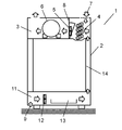
- FIG. 1 is a diagram illustrating a schematic cross-section illustrating the refrigerator in the first embodiment of the present disclosure.
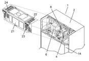
- FIG. 2 is an exploded perspective view showing an upper machine room of the refrigerator.
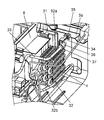
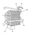
- FIG. 3 is a perspective view around the condenser installed in the upper machine room of the refrigerator.
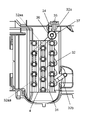
- FIG. 4 is a side view of the condenser.
- FIG. 5 is a side view showing the condenser of the refrigerator in the second embodiment of the present disclosure.
- FIG. 6 is a perspective view showing the refrigerator condenser in the third embodiment of the present disclosure.
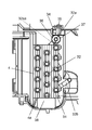
- FIG. 7 is a side view showing the refrigerator condenser in the third embodiment.
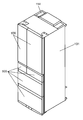
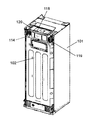
- FIG. 8 is a perspective view of the refrigerator in the fourth embodiment of the present disclosure.
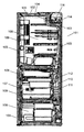
- FIG. 9 is a cross-sectional view of the refrigerator.
- FIG. 1 is a diagram illustrating a schematic cross-section illustrating the refrigerator in the first embodiment of the present disclosure.
- FIG. 2 is an exploded perspective view showing an upper machine room of the
- FIG. 10 is a rear perspective view of the refrigerator.
- FIG. 11 is an exploded perspective view showing a machine room portion of the refrigerator.
- FIG. 12 is a rear perspective view showing a machine room portion of the refrigerator.
- FIG. 13 is a side view of a heat exchanger serving as a condenser of the refrigerator.
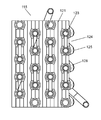
- FIG. 14 is the fin expansion front view which looked at the heat exchanger used as the condenser of the refrigerator from the front.
- FIG. 15 is a principal part expanded side view of the heat exchanger used as the condenser of the refrigerator.
- FIG. 16 is an operation explanatory view of fins of a heat exchanger that serves as a condenser of the refrigerator.
- FIG. 17 is a fin top view of the heat exchanger used as the condenser of the refrigerator.
- FIG. 18 is an explanatory diagram of the operation of the fins of the heat exchanger serving as the condenser of the refrigerator.
- FIG. 19 is a perspective view showing a conventional refrigerator
- the refrigerator according to the first aspect includes a machine room provided in the refrigerator main body, and a condenser that is arranged in the machine room and includes pipes penetrating through the fin group.
- the condenser is suspended in the machine room.
- the condenser Since the condenser is arranged in a suspended state, vibrations that are about to propagate to the condenser are absorbed without propagating to the condenser. Furthermore, since the condenser is in a suspended state, even if there is a weak vibration propagating to the condenser, the vibration is suppressed from being transmitted to the refrigerator body. Therefore, the vibration of the refrigerator body can be efficiently suppressed.
- the second aspect is the first aspect, wherein the condenser includes an inlet side pipe connected to the refrigerant pipe from the compressor.
- the inlet side pipe is elastically supported by a support member fixed to the machine room.
- the third aspect is the second aspect, wherein one end of the support is fixed to a part of the machine room.
- the condenser is supported in a suspended state by the ring-shaped portion provided at the other end of the support member embracing and supporting the inlet side pipe.
- the support becomes a cantilever-like structure, and the support itself exhibits a vibration absorbing effect. Therefore, the vibration suppression effect of the condenser can be further enhanced and further noise reduction can be achieved.
- the fourth aspect is the first aspect, wherein the inlet pipe and outlet pipe of the condenser are arranged together on either the upper, lower, left or right side of the condenser.
- WHEREIN The 1st aspect WHEREIN: The lower end surface of a condenser is supported by the vibration isolating foam.
- FIG. 1 is a diagram illustrating a schematic cross section illustrating the refrigerator according to the first embodiment of the present disclosure.
- the refrigerator 1 includes a refrigerator body 2, an upper machine room 3 installed at the upper back of the refrigerator body 2, a condenser 4, a first fan 5, and a compressor 6.
- a condenser 4 In the upper machine room 3, a condenser 4, a first fan 5, and a compressor 6 are installed in order from the windward side. By driving the first fan 5, the air 7 in the upper part of the refrigerator is sucked. . Thereby, the condenser 4 and the compressor 6 are air-cooled.
- the first fan 5 is attached to the fan ring 8, and the fan ring 8 divides the air path in the upper machine room 3 into the windward side and the leeward side of the first fan 5.
- the refrigerator 1 is the evaporation which stores the defrost water of the lower machine room 11 installed in the back lower part of the refrigerator main body 2, the 2nd fan 12, and a warehouse (not shown).
- the tray 13 and the communication air path 14 provided in the back corner part of the refrigerator main body 2 are further provided.
- a second fan 12 and an evaporating dish 13 are installed in order from the windward side. When the second fan 12 is driven, the air 9 near the lower portion of the refrigerator body 2 is sucked.
- the evaporation of the defrosted water stored in the evaporating dish 13 is promoted, and the air cooled by the evaporation of the defrosted water is supplied to the condenser 4 via the evaporating dish 13 and the communication air passage 14. .
- the second fan 12 has both the function of cooling the condenser 4 and the function of promoting evaporation of the defrosted water accumulated in the evaporating dish 13, thereby evaporating the defrosted water with a simple configuration.
- air having a temperature lower than that of the outside air can be supplied to the condenser.
- heat can be efficiently radiated in the upper machine room 3.
- the compressor 6 and the condenser 4 which are main heat sources are arranged in the upper machine room 3, the air 9 near the lower part of the refrigerator main body 2 sucked by the second fan 12 is stored in the refrigerator main body 2.
- the temperature is relatively lower than the air above. Therefore, it is desirable not to provide a main heat source in the lower machine room 11.
- a radiator (not shown) having a sufficiently smaller capacity than the condenser 4 is provided in the evaporating dish 13. You may arrange.
- FIG. 2 is a perspective view with the upper machine room cover of the refrigerator in Embodiment 1 removed.
- the refrigerator 1 is provided on the upper machine room cover 21, the upper machine room cover 21, the suction side top grill 22 that sucks air 9 from above the refrigerator 1, and the upper machine room cover 21.
- a suction-side rear grille 23 for sucking air 9 from the communication air passage 14 and a discharge-side grille 24 for exhausting upward of the refrigerator 1 are provided.
- the suction side rear grille 23 is configured to be recessed from the wall surface of the refrigerator body 2 above the communication air passage 14. Thereby, even when the back surface or side surface of the refrigerator 1 is installed close to the wall, the suction side rear grille 23 can communicate with the communication air passage 14. As a result, as described above, when the refrigerator 1 is installed in a limited space such as a system kitchen, air is sucked from the communication air passage 14 via the suction side rear grille 23, so that the upper machine room The influence of the high temperature exhaust discharged upward from 3 can be remarkably suppressed.
- FIG. 3 is a perspective view around the condenser installed in the upper machine room of the refrigerator in the first embodiment.
- FIG. 4 is a side view of the condenser.
- the condenser 4 is a plate fin type condenser that is configured by penetrating pipes 32 through a large number of fin groups 31. And the inlet side pipe 32a of the condenser 4 is connected with the refrigerant
- the condenser 4 is disposed along the vertical direction of the refrigerator 1.
- the inlet side pipe 32 a located at the top of the condenser 4 is elastically supported by a support 34 formed of a spring material, so that the condenser 4 is installed in a suspended state in the upper machine chamber 3. That is, one end of the support 34 is screwed to the partition wall 3a of the upper machine chamber 3 with a screw 35, and the inlet side pipe 32a is passed through a ring-shaped holding portion 36 provided at the other end of the support 34.
- the condenser 4 is held in a suspended state by the support 34.
- the ring-shaped holding portion 36 of the support 34 is provided with an elastic body 37 such as a rubber bush, and the inlet side pipe 32 a is held via the elastic body 37.
- the exit side pipe 32b is located in the lower part of the condenser 4, and has entered into the foam heat insulating material in the refrigerator main body 2 as described above.
- the first fan 5 and the second fan 12 are controlled so as to be driven simultaneously in conjunction with the compressor 6.
- air 9 is sucked from the upper rear surface of the refrigerator main body 2 of the refrigerator 1 through the suction side top grill 22, and the condenser 4 and the compressor 6 are cooled.
- the lower back air 9 is sucked through the lower machine chamber 11, the communication air passage 14, and the suction side rear grille 23, so that the influence of the high temperature exhaust exhausted upward from the upper machine chamber 3 is affected. It can be remarkably suppressed.
- the second fan 12 may be stopped and only the first fan 5 may be driven in conjunction with the compressor 6 to save energy. Moreover, when it is desired to increase the ability to evaporate the defrosted water in the evaporating dish 13, the second fan 12 may be driven as necessary.
- the compressor 6 thus cooled vibrates due to the suction, compression and discharge of the refrigerant, and the vibration tends to propagate from the refrigerant pipe 33 on the compressor outlet side to the condenser 4 via the inlet pipe 32a. .
- the vibration propagating to the condenser 4 is attenuated without propagating as it is because the condenser 4 is suspended. Moreover, even if there is weak vibration propagating to the condenser 4, since the condenser 4 is suspended, it is possible to prevent the vibration from being transmitted to the refrigerator body 2. Therefore, the vibration of the refrigerator main body 2 caused by the vibration of the condenser 4 can be efficiently suppressed.
- the condenser 4 is elastically supported by the support 34, and the elastic support of the condenser 4 by the support 34 is performed at the inlet side pipe 32 a portion connected to the refrigerant pipe 33 from the compressor 6. Yes. Thereby, propagation of vibration can be reduced efficiently.
- the vibration is absorbed by the inlet side pipe 32a serving as a vibration propagation port, the vibration suppressing effect of the condenser 4 itself is enhanced, and further, the vibration of the refrigerator body 2 is effectively suppressed to reduce the noise. Can be planned.
- vibration propagating from the refrigerant pipe 33 of the compressor 6 is also absorbed by the elastic body 37. Therefore, the vibration absorption effect by the elastic body 37 is also added, and the vibration of the condenser 4 is further suppressed, and the noise can be effectively reduced.
- the support 34 is screwed to the partition wall 3 a of the upper machine chamber 3 with screws 35.
- maintenance part 36 provided in the other end of the support tool 34 embraces the inlet side pipe 32a of the condenser 4, and supports the condenser 4 elastically.
- the support 34 is configured as a cantilever and absorbs vibrations by elastic deformation of the support 34 in the vertical direction. Therefore, the vibration suppressing effect of the condenser 4 can be further enhanced and further noise reduction can be achieved.
- the vibration suppression effect can be heightened effectively because the support tool 34 is made of a spring material.
- FIG. 5 is a side view of the condenser in the second embodiment.
- the inlet side pipe 32a is drawn out from the lower end portion of the condenser 4 as shown by a broken line 32aa in FIG. Are arranged together.
- the upper end portion of the condenser 4 on the side where the inlet side pipe 32a and the outlet side pipe 32b are not connected can freely move without being restricted by the inlet side pipe 32a or the like. Therefore, the condenser 4 is combined with the suspension effect to increase the vibration absorption effect, and more efficiently suppress the vibration of the condenser 4 to achieve noise reduction.
- inlet side pipe 32a and the outlet side pipe 32b may be arranged together on the upper end side of the condenser 4 or on either the left or right side.
- FIG. 6 is a perspective view of the condenser in the third embodiment.
- FIG. 7 is a side view of the condenser.
- one end side of the condenser 4 is such that the inlet side pipe 32a and the outlet side pipe 32b are located on the far side of the condenser 4 (the right end of the condenser 4 in FIG. 6 and the far side of the condenser 4 in FIG. 7). It is connected at the side edge).
- the other end side of the condenser 4 is a free end 4a.
- An anti-vibration foam 38 made of urethane foam or the like is interposed between the lower end surface of the free end 4a and the machine room bottom surface.
- the free end 4a of the condenser 4 is also supported by the weak elastic force of the vibration isolating foam 38.
- vibration generated at the free end 4a can be effectively damped.
- the anti-vibration foam 38 such as urethane foam is considerably softer and has a delicate restoring force than an elastic member such as rubber. Accordingly, the weak vibration that propagates even in the suspended support configuration is reliably absorbed, and the vibration can be effectively attenuated. Therefore, the reliability of the vibration suppressing action of the condenser 4 is increased. As a result, vibration of the entire condenser 4 can be more reliably suppressed, and further noise reduction can be realized.
- the pipe is connected to one end of the condenser 4 and the other end is the free end 4a.
- a support structure is not necessary. . What is necessary is just to use the vibration-proof foam 38 by the structure which supports the lower end surface of the condenser 4 elastically at least.
- Embodiment 4 of the present disclosure will be described with reference to the drawings using a configuration in which the heat exchanger is used as a refrigerator condenser as an example.
- FIG. 8 is a perspective view of the refrigerator according to the fourth embodiment of the present disclosure.
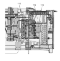
- FIG. 9 is a sectional view of the refrigerator.
- FIG. 10 is a rear perspective view of the refrigerator.
- FIG. 11 is an exploded perspective view showing a machine room portion of the refrigerator.
- FIG. 12 is a rear perspective view showing the main body and machine room case of the refrigerator.
- the refrigerator includes a refrigerator main body 101, an outer box 102 mainly using a steel plate, an inner box 103 formed of a hard resin such as ABS resin, an outer box 102, and an inner box 102.
- a foam heat insulating material 104 such as hard foam urethane filled between the box 103 and the box 103 is provided.
- the vacuum heat insulating material 105 is arrange
- a plurality of storage rooms such as a refrigerator compartment 106, a freezer compartment 107, and a vegetable compartment 108 are provided inside the refrigerator main body 101, and can be opened and closed by a door 109.
- a cooling chamber 110 is provided on the back surface of the freezing chamber 107 of the refrigerator main body 101. Cold air generated by a cooler 111 provided in the cooling chamber 110 is supplied to the refrigerator compartment 106, the freezer compartment 107, the vegetable compartment 108, and the like by the blower fan 112.
- a machine room 114 is provided at the upper rear of the refrigerator main body 101 as shown in FIG.
- a condenser 115 and a compressor 116 that constitute a refrigeration circuit together with the cooler 111, and a cooling fan 117 that cools the condenser 115 and the compressor 116 are installed in order from the windward side.
- the upper part and the back part of the machine room 114 are covered with a machine room cover 118.
- the machine room cover 118 is provided with a slit opening 119 for intake and an opening 120 for exhaust.
- the outside air is sucked from the slit opening 119 by the rotation of the cooling fan 117, the condenser 115 and the compressor 116 are air-cooled, and exhausted from the opening 120.
- the slit opening 119 is provided in the horizontal direction so as to face the apex portion of the condenser 115 which will be described later.
- FIG. 13 is a side view of a heat exchanger serving as a condenser.
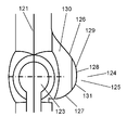
- FIG. 14 is an enlarged front view of the fin when the heat exchanger is viewed from the front.
- FIG. 15 is an enlarged side view of the main part of the heat exchanger.
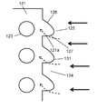
- FIG. 16 is an explanatory diagram of the operation of the fins of the heat exchanger.
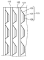
- FIG. 17 is a fin plan view of the heat exchanger.
- FIG. 18 is an explanatory diagram of the operation of the fin surface of the heat exchanger.
- a large number of thin plate-like vertically long fins 121 made of an aluminum alloy constituting a heat exchanger are arranged in parallel with an interval 122 through which air flows.
- the plurality of pipes 123 that pass through the fins 121 and in which the refrigerant flows are bent in, for example, four rows and upper and lower stages.
- the plurality of dust adhesion reducing portions 125 are devised in terms of shape so that cotton dust is not easily attached, and prevents a reduction in the air flow rate of the heat exchanger due to dust clogging between the fins 121.
- the dust adhesion reducing unit 125 includes an upward end surface 126 that is inclined upward, and a horizontal state (including a substantially horizontal state) that is shorter than the upward end surface 126 and positioned directly below the upward end surface 126. ) And a downward end face 127, and is formed in a triangular mountain shape that is difficult to get dust.
- the chevron-shaped portion 128 where the upward end surface 126 and the downward end surface 127 constituting the dust adhesion reducing portion 125 intersect is such that the top surface of the fin surface is a front view of the fin of FIG. 17, a plan view of FIG. As shown in the operation explanatory diagram of FIG. 18, the inclined surface 129 is inclined with respect to the air flow. Furthermore, the fin surface of the chevron shaped portion 128 includes a downstream inclined surface 130 that is further inclined on the downstream side of the inclined surface 129 in a direction intersecting the inclined surface 129.
- the fin 121 has a zigzag shape over the entire region in the air flow direction (between the left end and the right end of the fin 121 in FIG. 17).
- a round 131 is provided at the tip of the mountain-shaped portion 128 as shown in FIG. Thereby, it is considered to be safe for the user.
- the fin downstream end surface of the condenser 115 is a linear flat surface.
- the refrigerant compressed by the operation of the compressor 116 evaporates in the cooler 111 to generate cold air.
- the generated cold air is supplied to the refrigerator compartment 106, the freezer compartment 107, the vegetable compartment 108, and the like by the blower fan 112 to cool the food.
- the refrigerant flows to the condenser 115.
- the refrigerant is condensed in the condenser 115 by exchanging heat with the outside air sucked from the slit opening 119 of the machine room cover 118 by the cooling fan 117. Then, the refrigerant returns to the compressor 116 again and repeats the above operation.
- the outside air that exchanges heat with the condenser 115 enters the condenser 115 from the air inflow side end surface 124, exchanges heat with the pipe 123 through the fins 121, and flows through the interval 122 between the fins 121 to condense. It will pass through the vessel 115.
- the upper end surface 126 and the lower end surface 127 of the dust adhesion reducing portion 125 constituting the air inflow side end surface 124 of the condenser 115 have a smaller angle with respect to the inflowing air indicated by solid line arrows in FIG. hard.
- the upward end surface 126 of the dust adhesion reducing portion 125 is inclined with respect to the inflowing air flow. As a result, most of the dust mixed in the air that hits the upward end surface 126 flows downstream along the inclination of the upward end surface 126 and begins to concentrate in the valleys. Since the dimension of the upward end face 126 is long, the dust is thinly deposited on the entire surface, and an increase in air resistance is suppressed. Moreover, in the downward end surface 127, the downward end surface 127 is a horizontal state (a substantially horizontal state is included), and becomes an end surface in the same direction as the air flow. Therefore, dust accumulation hardly occurs, and even if dust accumulates, it falls due to gravity and air flow.
- the condenser 115 when the condenser 115 is viewed as a whole, the influence of clogging with dust can be reduced over a long period of time, and a decrease in heat exchange capability can be suppressed. Therefore, the energy saving performance can be improved by the amount that can suppress the decrease in heat exchange capacity.
- the fin surface at the apex portion of the chevron shaped portion 128 constituted by the upper end face 126 and the lower end face 127 of the dust adhesion reducing portion 125 is constituted by an inclined surface 129 inclined with respect to the air flow. Therefore, dust accumulation is further delayed, and clogging of the upward end face 126 can be suppressed.
- the fin tip cross section is also inclined with respect to the air flow direction, the air that directly collides with the edge of the apex portion of the chevron shaped portion 128 becomes a part of the shape shown by the arrow a in FIG.
- the dust itself caught on the apex of the part 128 can be reduced. Accordingly, it is possible to reduce the amount of dust itself that is caught in the apex edge of the chevron-shaped portion 128 and flows downstream along the upward end surface 126 and accumulates in the valley portion.
- the fin surface of the angle-shaped portion 128 is indicated by the arrow e in FIG. Turbulence is generated between the inclined surface 129 at the apex portion and the downstream inclined surface 130 at the downstream portion thereof.
- the turbulent flow causes an air flow separation phenomenon, and dust accumulation is suppressed.
- the fin 121 has a zigzag shape over the entire area in the air flow direction, an air flow separation phenomenon occurs on the surface of the entire fin area, and it is difficult for dust to adhere to and accumulate on the fin surface over the entire area in the air flow direction.
- the trough is less susceptible to air flow resistance caused by the pipe 123, so that the air flow rate becomes faster at the beginning of dust clogging. And the dust which is going to accumulate in a trough part falls off by the air with the said fast flow velocity. As a result, dust accumulation in the valley can be delayed.
- the slit opening 119 for taking in the outside air flowing into the condenser 115 may be provided so as to face the apex portion of the mountain-shaped portion 128 of the condenser 115.
- the air flowing in from the slit opening 119 flows into the chevron shaped portion 128 of the dust adhesion reducing portion 125 of the condenser 115 from the front thereof.
- this indication is not limited to this, and can be variously changed within the range which achieves the object of this indication. Needless to say.
- the heat exchanger is used as the condenser 115
- the present invention is not limited to this and may be used as an evaporator.
- the dust adhesion reducing unit 125 has exemplified the structure configured by the combination of the upward end surface 126 inclined upward and the downward end surface 127 in a horizontal state (including a substantially horizontal state), it is not limited thereto.
- the upward end surface 126 may be horizontal (including substantially horizontal) and the downward end surface 127 may be inclined downward, or both the upward end surface 126 and the downward end surface 127 may be inclined and the angle thereof may be They may be different from each other. What is necessary is just to select suitably according to a usage form.
- the refrigerator was illustrated as an apparatus which applies a heat exchanger, it is not restricted to this.
- Air-conditioning refrigeration equipment such as air conditioners, or commercial refrigeration equipment such as vending machines and showcases may also be used.
- the refrigerator according to the present embodiment includes plate-like fins, a plurality of pipes through which refrigerant flows, and a dust adhesion reducing unit disposed on the end surface of the fin on the air inflow side.
- the dust adhesion reducing portion includes a chevron-shaped portion composed of an upward end surface and a downward end surface having apexes on the air inflow side, and the fin surface at the apex portion of the chevron-shaped portion is an inclined surface.
- the dust itself which slips toward the downstream on the above-mentioned upward end surface and accumulates in a trough part can be reduced significantly. Therefore, it is possible to further reduce the influence of dust clogging, suppress a decrease in heat exchange capability, and improve energy saving and durability.
- the fin surface of the chevron-shaped portion may be further inclined in a direction intersecting the inclined surface on the downstream side of the inclined surface.
- a turbulent flow is generated between the inclined surface of the fin surface and the inclined portion of the downstream side at the apex portion of the chevron-shaped portion, and the turbulent flow causes a separation phenomenon of the air flow, which makes it difficult for dust to adhere and accumulate. Thereby, the fall of heat exchange capability can be suppressed further and energy-saving property and durability can be improved.
- the fins may have a zigzag shape over the entire air flow direction.
- the pipe penetrating through the portion of the fin that is closest to the air inflow side may be provided in the mountain-shaped portion and not provided in the valley portion.
- the valley is less susceptible to air flow resistance caused by pipes, so the air flow rate is high at the beginning of dust clogging. Thereby, the dust which is going to accumulate in a trough part falls off by the air with the said fast flow velocity. As a result, dust accumulation in the valley can be delayed. Accordingly, it is possible to further suppress a decrease in heat exchange capacity and improve energy saving and durability.
- the heat exchanger is installed in the machine room of the equipment body, and a slit opening is provided in the machine room, and the slit opening is formed by the chevron-shaped portion of the heat exchanger. You may provide so that it may oppose a vertex part.
- the refrigerator according to the present disclosure can suppress the vibration noise of the refrigerator body that is transmitted from the condenser, and can realize the silence of the refrigerator. Therefore, it can be applied not only to household refrigerators but also to other refrigerator-freezer products such as commercial refrigerators, showcases, and vending machines.
- Refrigerator 2 Refrigerator body 3 Upper machine room (machine room) DESCRIPTION OF SYMBOLS 4 Condenser 5 1st fan 6 Compressor 31 Fin group 32 Pipe 32a Inlet side pipe 32b Outlet side pipe 33 Refrigerant piping 34 Support tool 35 Screw 36 Ring-shaped holding part 37 Elastic body 38 Anti-vibration foam 101 Refrigerator main body 102 Outer box 103 Inner box 104 Foam insulation 105 Vacuum insulation 106 Refrigerating room (storage room) 107 Freezer Room 108 Vegetable Room 109 Door 110 Cooling Room 111 Cooler 112 Blower Fan 114 Machine Room 115 Condenser 116 Compressor 117 Cooling Fan 118 Machine Room Cover 119 Slit Opening 120 Opening 121 Fin 122 Spacing 123 Pipe 124 Air Inflow Side End Face 125 Dust adhesion reducing portion 126 Upward end surface 127 Downward end surface 128 Angle-shaped portion 129 Inclined surface 130 Downstream-side inclined surface 131 R
Landscapes
- Engineering & Computer Science (AREA)
- Chemical & Material Sciences (AREA)
- Combustion & Propulsion (AREA)
- Physics & Mathematics (AREA)
- Mechanical Engineering (AREA)
- Thermal Sciences (AREA)
- General Engineering & Computer Science (AREA)
- Devices That Are Associated With Refrigeration Equipment (AREA)
Abstract
La présente invention concerne un réfrigérateur comportant : une chambre à moteur reliée à un corps de réfrigérateur ; et un condenseur disposé dans la chambre à moteur, le condenseur étant conçu pour disposer un tuyau passant à travers un groupe d'ailettes. Le condenseur est installé dans la chambre à moteur dans un état suspendu. Les vibrations, qui pourraient autrement se propager à travers le condenseur, sont ainsi absorbées par le condenseur sans se propager. En outre, même dans le cas d'une faible vibration se propageant à travers le condenseur, la transmission de ladite vibration au corps du réfrigérateur est réduite au minimum. Par conséquent, il est possible de réduire efficacement au minimum les vibrations du corps de réfrigérateur.
Priority Applications (2)
| Application Number | Priority Date | Filing Date | Title |
|---|---|---|---|
| JP2017527084A JPWO2017006565A1 (ja) | 2015-07-09 | 2016-07-07 | 冷蔵庫 |
| CN201680039212.8A CN107735632A (zh) | 2015-07-09 | 2016-07-07 | 冷藏库 |
Applications Claiming Priority (4)
| Application Number | Priority Date | Filing Date | Title |
|---|---|---|---|
| JP2015-137460 | 2015-07-09 | ||
| JP2015137460 | 2015-07-09 | ||
| JP2015146700 | 2015-07-24 | ||
| JP2015-146700 | 2015-07-24 |
Publications (1)
| Publication Number | Publication Date |
|---|---|
| WO2017006565A1 true WO2017006565A1 (fr) | 2017-01-12 |
Family
ID=57686215
Family Applications (1)
| Application Number | Title | Priority Date | Filing Date |
|---|---|---|---|
| PCT/JP2016/003223 Ceased WO2017006565A1 (fr) | 2015-07-09 | 2016-07-07 | Réfrigérateur |
Country Status (3)
| Country | Link |
|---|---|
| JP (1) | JPWO2017006565A1 (fr) |
| CN (1) | CN107735632A (fr) |
| WO (1) | WO2017006565A1 (fr) |
Cited By (2)
| Publication number | Priority date | Publication date | Assignee | Title |
|---|---|---|---|---|
| JP2019078457A (ja) * | 2017-10-24 | 2019-05-23 | パナソニックIpマネジメント株式会社 | 低温ショーケース |
| JP2019158196A (ja) * | 2018-03-09 | 2019-09-19 | 東芝ライフスタイル株式会社 | 冷蔵庫 |
Families Citing this family (1)
| Publication number | Priority date | Publication date | Assignee | Title |
|---|---|---|---|---|
| AU2024430251A1 (en) | 2024-08-29 | 2026-03-19 | Guangzhou Xin'an Trading Co., Ltd. | Sealing assembly for evaporator |
Citations (7)
| Publication number | Priority date | Publication date | Assignee | Title |
|---|---|---|---|---|
| JPS63159160U (fr) * | 1987-04-02 | 1988-10-18 | ||
| JPH11159941A (ja) * | 1997-11-28 | 1999-06-15 | Sharp Corp | 電気冷蔵庫 |
| US6260373B1 (en) * | 2000-02-16 | 2001-07-17 | American Standard International Inc. | Heat exchanger with double vibration isolation |
| JP2002310590A (ja) * | 2001-04-16 | 2002-10-23 | Mitsubishi Heavy Ind Ltd | コンデンサ |
| JP2008101814A (ja) * | 2006-10-18 | 2008-05-01 | Matsushita Electric Ind Co Ltd | 冷蔵庫 |
| JP2013068383A (ja) * | 2011-09-26 | 2013-04-18 | Panasonic Corp | 冷蔵庫 |
| JP2014020680A (ja) * | 2012-07-19 | 2014-02-03 | Toshiba Corp | 冷蔵庫 |
Family Cites Families (1)
| Publication number | Priority date | Publication date | Assignee | Title |
|---|---|---|---|---|
| WO2013046633A1 (fr) * | 2011-09-26 | 2013-04-04 | パナソニック株式会社 | Réfrigérateur |
-
2016
- 2016-07-07 CN CN201680039212.8A patent/CN107735632A/zh active Pending
- 2016-07-07 WO PCT/JP2016/003223 patent/WO2017006565A1/fr not_active Ceased
- 2016-07-07 JP JP2017527084A patent/JPWO2017006565A1/ja active Pending
Patent Citations (7)
| Publication number | Priority date | Publication date | Assignee | Title |
|---|---|---|---|---|
| JPS63159160U (fr) * | 1987-04-02 | 1988-10-18 | ||
| JPH11159941A (ja) * | 1997-11-28 | 1999-06-15 | Sharp Corp | 電気冷蔵庫 |
| US6260373B1 (en) * | 2000-02-16 | 2001-07-17 | American Standard International Inc. | Heat exchanger with double vibration isolation |
| JP2002310590A (ja) * | 2001-04-16 | 2002-10-23 | Mitsubishi Heavy Ind Ltd | コンデンサ |
| JP2008101814A (ja) * | 2006-10-18 | 2008-05-01 | Matsushita Electric Ind Co Ltd | 冷蔵庫 |
| JP2013068383A (ja) * | 2011-09-26 | 2013-04-18 | Panasonic Corp | 冷蔵庫 |
| JP2014020680A (ja) * | 2012-07-19 | 2014-02-03 | Toshiba Corp | 冷蔵庫 |
Cited By (3)
| Publication number | Priority date | Publication date | Assignee | Title |
|---|---|---|---|---|
| JP2019078457A (ja) * | 2017-10-24 | 2019-05-23 | パナソニックIpマネジメント株式会社 | 低温ショーケース |
| JP2019158196A (ja) * | 2018-03-09 | 2019-09-19 | 東芝ライフスタイル株式会社 | 冷蔵庫 |
| JP7032186B2 (ja) | 2018-03-09 | 2022-03-08 | 東芝ライフスタイル株式会社 | 冷蔵庫 |
Also Published As
| Publication number | Publication date |
|---|---|
| CN107735632A (zh) | 2018-02-23 |
| JPWO2017006565A1 (ja) | 2018-04-19 |
Similar Documents
| Publication | Publication Date | Title |
|---|---|---|
| CN107621114B (zh) | 一种风冷冰箱 | |
| CN102317712B (zh) | 冰箱 | |
| JP2009030864A (ja) | 冷蔵庫 | |
| EP3462111B1 (fr) | Ensemble de dissipation de chaleur et dispositif de réfrigération | |
| JP2013019623A (ja) | 冷蔵庫 | |
| JPWO2017006565A1 (ja) | 冷蔵庫 | |
| KR20090114044A (ko) | 냉장고 | |
| WO2004113806A1 (fr) | Dispositif de refroidissement | |
| CN104380015B (zh) | 冰箱 | |
| JP5575532B2 (ja) | 冷蔵庫 | |
| CN111609613A (zh) | 送风机位于蒸发器横向侧方上游的冰箱 | |
| JP2012255638A (ja) | 冷蔵庫 | |
| JP3093636B2 (ja) | 冷蔵庫 | |
| CN111609628B (zh) | 排水口设置有过滤板的冰箱 | |
| JP7209554B6 (ja) | 冷蔵庫 | |
| CN219063862U (zh) | 制冷设备 | |
| CN110375481A (zh) | 底部具有双冷凝器结构的冰箱 | |
| EP4006458B1 (fr) | Réfrigérateur doté d'un évaporateur disposé de manière oblique | |
| JPWO2005124249A1 (ja) | 冷却装置 | |
| CN210035945U (zh) | 蒸发器具有弯折结构的冰箱 | |
| CN112113381A (zh) | 蒸发器异形的冰箱 | |
| JP2016044824A (ja) | 冷蔵庫 | |
| CN219390180U (zh) | 半导体制冷的制冷设备 | |
| CN216626518U (zh) | 一种含有热管的多模式热交换机房 | |
| JP2011080692A (ja) | 冷蔵庫 |
Legal Events
| Date | Code | Title | Description |
|---|---|---|---|
| 121 | Ep: the epo has been informed by wipo that ep was designated in this application |
Ref document number: 16821040 Country of ref document: EP Kind code of ref document: A1 |
|
| ENP | Entry into the national phase |
Ref document number: 2017527084 Country of ref document: JP Kind code of ref document: A |
|
| NENP | Non-entry into the national phase |
Ref country code: DE |
|
| 122 | Ep: pct application non-entry in european phase |
Ref document number: 16821040 Country of ref document: EP Kind code of ref document: A1 |