WO2017006572A1 - Gabarit d'installation d'accessoire et procédé d'installation d'accessoire - Google Patents
Gabarit d'installation d'accessoire et procédé d'installation d'accessoire Download PDFInfo
- Publication number
- WO2017006572A1 WO2017006572A1 PCT/JP2016/003255 JP2016003255W WO2017006572A1 WO 2017006572 A1 WO2017006572 A1 WO 2017006572A1 JP 2016003255 W JP2016003255 W JP 2016003255W WO 2017006572 A1 WO2017006572 A1 WO 2017006572A1
- Authority
- WO
- WIPO (PCT)
- Prior art keywords
- attachment
- workpiece
- jig
- bars
- engaging part
- Prior art date
- Legal status (The legal status is an assumption and is not a legal conclusion. Google has not performed a legal analysis and makes no representation as to the accuracy of the status listed.)
- Ceased
Links
Images






Classifications
-
- B—PERFORMING OPERATIONS; TRANSPORTING
- B21—MECHANICAL METAL-WORKING WITHOUT ESSENTIALLY REMOVING MATERIAL; PUNCHING METAL
- B21J—FORGING; HAMMERING; PRESSING METAL; RIVETING; FORGE FURNACES
- B21J13/00—Details of machines for forging, pressing, or hammering
- B21J13/08—Accessories for handling work or tools
- B21J13/085—Accessories for handling work or tools handling of tools
-
- B—PERFORMING OPERATIONS; TRANSPORTING
- B21—MECHANICAL METAL-WORKING WITHOUT ESSENTIALLY REMOVING MATERIAL; PUNCHING METAL
- B21J—FORGING; HAMMERING; PRESSING METAL; RIVETING; FORGE FURNACES
- B21J5/00—Methods for forging, hammering, or pressing; Special equipment or accessories therefor
- B21J5/06—Methods for forging, hammering, or pressing; Special equipment or accessories therefor for performing particular operations
- B21J5/08—Upsetting
-
- B—PERFORMING OPERATIONS; TRANSPORTING
- B21—MECHANICAL METAL-WORKING WITHOUT ESSENTIALLY REMOVING MATERIAL; PUNCHING METAL
- B21K—MAKING FORGED OR PRESSED METAL PRODUCTS, e.g. HORSE-SHOES, RIVETS, BOLTS OR WHEELS
- B21K23/00—Making other articles
- B21K23/04—Making other articles flanged articles
-
- B—PERFORMING OPERATIONS; TRANSPORTING
- B30—PRESSES
- B30B—PRESSES IN GENERAL
- B30B15/00—Details of, or accessories for, presses; Auxiliary measures in connection with pressing
- B30B15/02—Dies; Inserts therefor; Mounting thereof; Moulds
- B30B15/028—Loading or unloading of dies, platens or press rams
-
- B—PERFORMING OPERATIONS; TRANSPORTING
- B30—PRESSES
- B30B—PRESSES IN GENERAL
- B30B15/00—Details of, or accessories for, presses; Auxiliary measures in connection with pressing
- B30B15/08—Accessory tools, e.g. knives; Mountings therefor
Definitions
- the present invention relates to an attachment installing jig and an attachment installing method for installing an attachment into a workpiece processing machine.
- a workpiece is attached to a workpiece attaching hole of an attachment installed in the workpiece processing machine.
- a shaft-diameter enlarging apparatus is an example of such a workpiece processing machine.
- a related art shaft-diameter enlarging apparatus has holder units configured to hold respective ends of a rod-shaped metal workpiece disposed along a reference line. These holder units are moved toward and away from each other along the reference line, while rotating, and further, one of the holder units is inclined with respect to the other holder unit, thereby forming a collar having an enlarged diameter at a middle of the workpiece (see, e.g., JP2008-200696A).
- each of the holder units includes a support cylinder and a spindle rotatably provided in the support cylinder, and a sleeves (attachment) is fitted to the spindle.
- the attachment is changed depending on different types of the workpiece. In other words, various kinds of the attachments are installed in accordance with a shape of the workpiece.
- the attachment is selected in accordance with the workpiece and is manually carried to a location where the holder unit is provided to manually install the attachment to the spindle.
- Illustrative aspects of the present invention provide an attachment installing jig and an attachment installing method in which carrying and installing an attachment to a workpiece processing machine can be easily carried out.
- a jig is provided to install an attachment having a workpiece attaching hole into the workpiece processing machine.
- the jig includes an attachment holding part configured to hold the attachment, and a plurality of bars provided on the attachment holding part and arranged parallel to each other.
- the bars are arranged to contact a reference part provided on a circle having a center at a position at which an axis of the workpiece attaching hole is set when the attachment is installed into the workpiece processing machine.
- An axis of each of the bars is positioned on a circle having a center at the axis of the workpiece attaching hole of the attachment held in the attachment holding part.
- the attachment is held in the attachment holding part, and in this state, the attachment installing jig is moved to the workpiece processing machine using a carrying machine such as a crane. Then, the bars are made to contact the reference part provided on the workpiece processing machine.
- the reference part with which the bars are contacted are provided on the circle having a center at the position at which the axis of the workpiece attaching hole is set when the attachment is installed in the workpiece processing machine. Therefore, by bringing the bars in contact with the reference part, the attachment is positioned with respect to the position at which the axis of the workpiece attaching hole is set.
- the attachment can be easily carried to the workpiece processing machine by means of the attachment installing jig.
- positioning of the attachment with respect to the workpiece processing machine can be performed by bringing the bars in contact with the reference part of the workpiece processing machine, and therefore, the installing work can be easily carried out.
- the attachment holding part may include a frame, an attachment engaging part to be engaged with the attachment, and a retracting mechanism configured to retract the attachment engaging part toward a center part of the frame.
- the jig may further include a push-out mechanism configured to push out the attachment engaging part toward an end part of the frame.
- the attachment engaging part may include a first contact part configured to contact the attachment when the attachment is retracted by the retracting mechanism, and a second contact part configured to contact the attachment when the attachment is pushed out by the push-out mechanism.
- the attachment engaging part may include a first attachment engaging part and a second attachment engaging part arranged in a pair at both sides of the center part of the frame.
- the retracting mechanism and the push-out mechanism may be configured as a pantograph mechanism.
- the pantograph mechanism includes a first link and a second link each having one end rotatably connected to the first attachment engaging part, a third link and a fourth link each having one end rotatably connected to the second attachment engaging part, a first block rotatably connected to the other end of the first link and to the other end of the third link, a second block rotatably connected to the other end of the second link and to the other end of the fourth link, and an approaching and separating mechanism configured to move the first block and the second block toward and away from each other.
- the bars are brought into contact with the reference parts of the workpiece processing machine, and in this state, the push-out mechanism is operated.
- the first block and the second block are moved toward and away from each other.
- the first attachment engaging part and the second attachment engaging part are separated from each other, and these attachment engaging parts which are respectively engaged with the attachment are moved toward the end part of the frame.
- the attachment is installed in the workpiece processing machine.
- the approaching and separating mechanism may include a female screw part formed in each of the first block and the second block, and a male screw part screwed into the female screw part.
- a rotation amount of the male screw part is proportional to a moving amount of the first block with respect to the second block.
- a handle may be coupled to an end of the male screw part by a universal joint.
- the pantograph mechanism may be provided on the frame so as to be movable parallel to the bars, and a first stopper configured to restrict a movement of the first attachment engaging part along an axial direction of the bars and a second stopper configured to restrict a movement of the second attachment engaging part along the axial direction of the bars may be provided on the frame. Sizes and weights of the attachments are sometimes different between the attachment which is engaged with the first attachment engaging part and the attachment which is engaged with the second attachment engaging part. When the pantograph mechanism is operated in a state where the attachments having the different weights are engaged with these attachment engaging parts, only one of the first attachment engaging part and the second attachment engaging part, for example, the first attachment engaging part which is engaged with the lighter attachment is moved to the center part of the frame.
- the first attachment engaging part and the second attachment engaging part When one of the first attachment engaging part and the second attachment engaging part is moved to the center part of the frame, the one attachment engaging part comes into contact with one of the first stopper and the second stopper thereby to restrict the movement. Thereafter, the other of the first attachment engaging part and the second attachment engaging part, for example, the attachment engaging part which is engaged with the heavier attachment is moved to the center part of the frame. When the other of the first attachment engaging part and the second attachment engaging part is moved to the center part of the frame, the other attachment engaging part comes into contact with the other of the first stopper and the second stopper, thereby to restrict the movement. In this manner, the first attachment engaging part and the second attachment engaging part are positioned in the center part of the frame, in a state where they are respectively engaged with the attachments. Therefore, even when there is a difference in weight between the attachment engaged with the first attachment engaging part and the attachment engaged with the second attachment engaging part, it is possible to reliably retract the attachments toward the center part of the frame.
- the workpiece processing machine may be a shaft-diameter enlarging apparatus configured to form a collar having an enlarged diameter at a middle of a rod-shaped metal workpiece, and the reference part may be an outer peripheral part of a spindle to which the attachment is mounted.
- the shaft-diameter enlarging apparatus is provided, in advance, with the spindles to which the attachments are to be mounted.
- Each of the spindles has a projected tip end, and an outer peripheral part of the projected tip end is formed in a shape of the circle having the center at the position at which the axis of the workpiece attaching hole is set.
- a method is provided to install an attachment into a workpiece processing machine using a jig.
- the jig includes an attachment holding part configured to hold the attachment having a workpiece attaching hole, and a plurality of bars provided on the attachment holding part and arranged parallel to each other. An axis of each of the bars is positioned on a circle having a center at an axis of the workpiece attaching hole of the attachment held by the attachment holding part.
- the method includes moving the jig to the workpiece processing machine in a state in which the attachment is held by the attachment holding part, and bringing the bars in contact with a reference part provided on a circle having a center at a position at which the axis of the workpiece attaching hole is set when the attachment is installed in the workpiece processing machine.
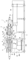
- Fig. 1 is a schematic sectional view showing an overall structure of a shaft-diameter enlarging apparatus which is provided with an attachment installing jig according to an embodiment of the invention.
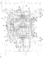
- Fig. 2 is a plan view of the shaft-diameter enlarging apparatus.
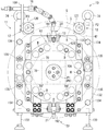
- Fig. 3 is a front view of the attachment installing jig in this embodiment.
- Fig. 4 is a side view of the attachment installing jig.
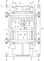
- Fig. 5 is a plan view of the attachment installing jig.
- Fig. 6 is a front view showing a jig mounting member in a state where the attachment installing jig is mounted.
- Fig. 1 is a schematic sectional view showing an overall structure of a shaft-diameter enlarging apparatus which is provided with an attachment installing jig according to an embodiment of the invention.
- Fig. 2 is a plan view of the shaft-diameter enlarging apparatus.
- Fig. 7 is a side view showing the jig mounting member in a state where the attachment installing jig is mounted.
- Fig. 8 is a plan view showing the jig mounting member in a state where the attachment installing jig is mounted.
- Fig. 9 is a side view partly cut away, showing a drive-side attachment.
- Fig. 10 is a partial front view showing the other part of the drive-side attachment.
- Fig. 11 is a side view partly cut away, showing a driven-side attachment.
- Fig. 12A is a side view partly cut away, showing an adapter for the drive-side attachment.
- Fig. 12B is a side view partly cut away, showing an adapter for the driven-side attachment.
- Fig. 12C is a plan view of the adapter.
- the attachment installing jig is used when installing attachments into a workpiece processing machine.
- the workpiece processing machine to which the embodiment is applied is a shaft-diameter enlarging apparatus for forming a collar having an enlarged diameter, in a middle of a rod-shaped metal workpiece.
- Figs. 1 and 2 illustrate an overall structure of the shaft-diameter enlarging apparatus.
- a shaft-diameter enlarging apparatus 1 includes a frame 2, a pair of support walls 3 which are provided at one end side of the frame 2, a drive-side holder unit 4 which is provided between a pair of the support walls 3, and a driven-side holder unit 5 which is provided in a center part of the frame 2.
- the drive-side holder unit 4 is provided with a unit frame 40.
- the unit frame 40 includes a pair of side plates 40A which are disposed near the support walls 3, and a bottom plate 40B which connects respective lower ends of these side plates 40A to each other.
- a support cylinder 41 in a shape of a block is connected to upper parts of the side plates 40A, and a spindle 42 is rotatably provided inside the support cylinder 41.
- the spindle 42 holds a drive-side attachment 61 at a side close to the driven-side holder unit 5.
- An outer peripheral part R of the spindle 42 which is exposed from the support cylinder 41 toward the driven-side holder unit 5 is set to be a reference part S for mounting the drive-side attachment 61 to the spindle 42.
- a discharging cylinder 43 for discharging a workpiece from the drive-side attachment 61 is connected to the spindle 42.
- the drive-side attachment 61 is disposed in such a manner that an axis of a workpiece attaching hole 61A is aligned with an axis position P0.
- the workpiece attaching hole 61A is a hole to which one end of the rod-shaped metal workpiece (not shown) is attached.
- Parts of the side plates 40A which are protruded from the support cylinder 41 are rotatably held by the support plates 3 by way of a shaft 41A.
- the bottom plate 40B is provided with a tilting cylinder 44 for tilting the drive-side holder unit 4 around the shaft 41A.
- the unit frame 40 is provided with an electric motor 45.
- the electric motor 45 is a motor for rotating the spindle 42 and the drive-side attachment 61 by way of a belt 45A.
- the driven-side holder unit 5 includes a slide table 55 which is provided so as to move back and forth with respect to the drive-side holder unit 4 in the frame 2, and a pressurizing cylinder 56 for moving the slide table 55 back and forth.
- the slide table 55 is provided with a support cylinder 51 in a shape of a block.
- a spindle 42 is rotatably provided inside the support cylinder 51.
- the spindle 42 holds a driven-side attachment 62 at a side close to the drive-side holder unit 4.
- An outer peripheral part R of the spindle 42 which is exposed from the support cylinder 51 toward the drive-side holder unit 4 is set to be a reference part S for mounting the driven-side attachment 62 to the spindle 42.
- a discharging cylinder 53 for discharging the workpiece from the driven-side attachment 62 is connected to the spindle 42.
- the driven-side attachment 62 is disposed in such a manner that an axis of a workpiece attaching hole 62A is aligned with an axis position PO.
- the workpiece attaching hole 62A is a hole to which the other end of the rod-shaped metal workpiece is attached.
- the spindle 42 and the drive-side attachment 61 are tilted around the shaft 41A by the tilting cylinder 44, and at the same time, rotated in an axial direction by the electric motor 45. Further, the spindle 42 and the driven-side attachment 62 are advanced toward the drive-side attachment 61 by the pressurizing cylinder 56. In this manner, a collar having an enlarged diameter is formed in the middle of the rod-shaped metal workpiece.
- An attachment installing jig 10 in this embodiment can be disposed at the reference part S of the spindle 42 of the drive-side holder unit 4 and at the reference part S of the spindle 42 of the driven-side holder unit 5.
- the attachment installing jig 10 includes an attachment holding part 11 for holding the attachments, and a pair of bars 12 which are provided in the attachment holding part 11 and arranged parallel to each other.
- the drive-side attachment 61 includes an attachment body 610, and an adapter 611 which is detachably provided on the attachment body 610.
- the adapter 611 is formed in a disc-like shape, and integrally coupled to the attachment body 610 by means of bolts B, at predetermined positions of an outer peripheral edge thereof.
- An engagement disc 612 is provided in a core part of the adapter 611.
- the driven-side attachment 62 includes an attachment body 620, and an adapter 621 which is detachably provided on the attachment body 620 in the same manner as the drive-side attachment 61.
- the adapter 621 is formed in a disc-like shape, and integrally coupled to the attachment body 620 by means of bolts B, at predetermined positions of an outer peripheral edge thereof.
- An engagement disc 622 is provided in a core part of the adapter 621.
- the adapters 611, 621 are respectively provided with attachment hanging metal fittings 63 in outer peripheral parts thereof.
- the attachment hanging metal fittings 63 are formed of eyebolts or the like.
- the attachment holding part 11 includes a frame 13, a first attachment engaging part 71 which is movably provided at one end of the frame 13 and engaged with the drive-side attachment 61, a second attachment engaging part 72 which is movably provided at the other end of the frame 13 and engaged with the driven-side attachment 62, a pantograph mechanism 15 for retracting the first attachment engaging part 71 and the second attachment engaging part 72 toward a center part of the frame 13 and pushing them out toward both end parts of the frame 13, and a universal joint 16 which is coupled to the pantograph mechanism 15.
- the frame 13 has walls 131, 132 which are provided at both sides of the center part of the frame 13 so as to be opposed to each other, leg portions 133 which are fixed to lower ends of the walls 131, 132, and a plurality of connecting rods 134 for interconnecting the walls 131, 132.
- the two bars 12, the connecting rods 134, and guide rods 135 are arranged parallel to each other.
- the walls 131, 132 are respectively formed with windows 13C through which the drive-side attachment 61 and the driven-side attachment 62 are allowed to pass.
- the first attachment engaging part 71 has a first plate 710, an engaging hook 70 which is provided in a center part of a front face of the first plate 710, and a plurality of attachment receiving members 70F which are provided in a lower end part of the first plate 710.
- the first plate 710 has a long-length plate part 710A, short-length plate parts 710B which are provided at both ends of the long-length plate part 710A, and end plate parts 710C which are provided on the short-length plate parts 710B.
- the engaging hook 70 has a gap with respect to the first plate 710, for containing the engagement disc 612 of the adapter 611, and has an arc-shaped engaging part 70A which opens downward.
- the engagement disc 612 of the adapter 611 is engaged with the engaging part 70A from the downward opening.
- a surface of the engaging hook 70 opposed to the first plate 710 is a first contact part 701 which comes into contact with a back face of the engagement disc 612 of the adapter 611.
- a front face of the first plate 710 is a second contact part 702 which comes into contact with the engagement disc 612.
- the attachment receiving members 70F support a lower part of the outer peripheral face of the drive-side attachment 61.
- the second attachment engaging part 72 has substantially the same structure as the first attachment engaging part 71.
- the second attachment engaging part 72 has a second plate 720, an engaging hook 70 which is provided on a front face of the second plate 720, and a plurality of attachment receiving members 70F which are provided in a lower end part of the second plate 720.
- the second plate 720 has the same structure as the first plate 710.
- the engaging hook 70 has a gap with respect to the second plate 720, for containing the engagement disc 622 of the adapter 621, and has an arc-shaped engaging part 72A which opens downward.
- the engagement disc 622 of the adapter 621 is engaged with the engaging part 72A from the downward opening.
- a surface of the engaging hook 70 opposed to the second plate 720 is a first contact part 701 which comes into contact with a back face of the engagement disc 622 of the adapter 621.
- a front face of the second plate 720 is a second contact part 702 which comes into contact with the engagement disc 622.
- the attachment receiving members 70F support a lower part of the outer peripheral face of the driven-side attachment 62.
- the first plate 710 and the second plate 720 are respectively provided with jig hanging metal fittings 74, at upper ends thereof.
- the jig hanging metal fittings 74 are formed of, for example, eyebolts.
- Respective both ends of the first plate 710 and the second plate 720 are movably supported by the guide rods 135 which are provided on the walls 131, 132.
- the frame 13 is provided with a first stopper (not shown) for restricting the movement of the first plate 710 toward the end part of the frame 13, and a second stopper (not shown) for restricting the movement of the second plate 720 toward the end part of the frame 13.
- the pantograph mechanism 15 functions as a retracting mechanism 15A for retracting the first and second attachment engaging parts 71, 72 toward the center part of the frame 13, and also functions as a push-out mechanism 15B for pushing out the first and second attachment engaging parts 71, 72 toward the end parts of the frame 13.
- the pantograph mechanism 15 includes a pair of a first link 181 and a second link 182 which are rotatably connected to the first plate 710 at respective one ends thereof, a pair of a third link 183 and a fourth link 184 which are rotatably connected to the second plate 720 at respective one ends thereof, a first block 191 which is rotatably connected to the other end of the first link 181 and the other end of the third link 183, a second block 192 which is rotatably connected to the other end of the second link 182 and the other end of the fourth link 184, and an approaching and separating mechanism 20 for moving the first block 191 and the second block 192 toward and away from each other.
- the one end of the first link 181 is rotatably supported by a fixed part 180 which is fixed to a side face of the first plate 710 in the center part thereof, and the other end of the first link 181 is rotatably supported by the first block 191.
- the two first links 181 are provided interposing the fixed part 180 and the first block 191 between them.
- the one end of the second link 182 is rotatably supported by the fixed part 180, and the other end of the second link 182 is rotatably supported by the second block 192.
- the two second links 182 are provided interposing the fixed part 180 and the second block 192 between them.
- the one end of the third link 183 is rotatably supported by a fixed part 180 which is fixed to a side face of the second plate 720 in the center part thereof, and the other end of the third link 183 is rotatably supported by the first block 191.
- the two third links 183 are provided interposing the fixed part 180 and the first block 191 between them.
- the one end of the fourth link 184 is rotatably supported by the fixed part 180 of the second plate 720, and the other end of the fourth link 184 is rotatably supported by the second block 192.
- the two fourth links 184 are provided interposing the fixed part 180 and the second block 192 between them.
- the first block 191 and the second block 192 are arranged in parallel in a vertical direction.
- the approaching and separating mechanism 20 includes a female screw part 20A which is formed in the first block 191 and the second block 192, extending in the vertical direction, and a male screw part 21 which is engaged with the female screw part 20A.
- the male screw part 21 is provided extending in the vertical direction, and one end of the universal joint 16 is connected to an upper end of the male screw part 21.
- the other end of the universal joint 16 to which a handle is connected is extended in a horizontal direction.
- the universal joint 16 is locked to a mounting plate 16A, and the mounting plate 16A is fixed to one of the bars 12.
- Each of the bars 12 includes a columnar body 120 which is provided on the walls 131, 132 so as to move in an axial direction, columnar engaging parts 121 which are respectively fixed to both ends of the columnar body 120, two fixed rings 122 which are respectively fixed to a center side of the columnar body 120, and springs 123 which are provided between the fixed rings 122 and the walls 131, 132.
- the springs 123 function as buffers when the one end of the bar 12 collides against the shaft-diameter enlarging apparatus 1 or other parts. Peripheral faces of the engaging parts 121 can be brought into contact with the reference parts S of the spindles 42.
- the reference parts S are respectively formed on the outer peripheral parts R of the spindles 42, specifically, on circles around axis positions P0 of the respective workpiece attaching holes 61A, 62A when the drive-side attachment 61 and the driven-side attachment 62 are mounted to the spindles 42.
- respective axes P2 of the two bars 12 are positioned on imaginary circles Q around axes P1 of the workpiece attaching holes 61A, 62A of the drive-side attachment 61 and the driven-side attachment 62 (in Fig. 4, only a part of the imaginary circle Q is shown).
- the imaginary circles Q and the outer peripheral parts R of the spindles 42 are concentric around the axes P1 of the workpiece attaching holes 61A, 62A.
- a radius of the imaginary circle Q is equal to a sum of a radius of the outer peripheral part of the spindle 42 and a radius of the bar 12.
- the jig mounting member 8 When setting the drive-side attachment 61 and the driven-side attachment 62 on the attachment installing jig 10 having the above described structure, a jig mounting member 8 as shown in Figs. 6 to 8 is used.
- the jig mounting member 8 includes a base member 80 having a rectangular shape in a plan view, on which the attachment installing jig 10 is mounted, a first holding member 81 which is provided at one end side of the base member 80 for holding the drive-side attachment 61, a second holding member 82 which is provided at the other end side of the base member 80 for holding the driven-side attachment 62, and leg portions 83 which are provided on a lower face of the base member 80.
- the base member 80 is provided with member hanging metal fittings 84 for hanging the jig mounting member 8, at four corners thereof.
- the member hanging metal fittings 84 are formed of, for example, eyebolts.
- the first holding member 81 includes a pair of posts 85, a short-length member 86 which is disposed between the posts 85, and a pair of inclined members 87 respectively bridging upper ends of the posts 85 and an upper end of the short-length member 86.
- the lower face of the outer periphery of the drive-side attachment 61 comes into contact with upper edges of a pair of the inclined members 87.
- an axis of the workpiece attaching hole 61A of the drive-side attachment 61 is aligned with the axis of the workpiece attaching hole 61A of the drive-side attachment 61 which is mounted on the first attachment engaging part 71.
- the second holding member 82 has substantially the same structure as the first holding member 81, and includes a pair of posts 85, a short-length member 86, and a pair of inclined members 87.
- the lower face of the outer periphery of the driven-side attachment 62 comes into contact with upper edges of a pair of the inclined members 87.
- an axis of the workpiece attaching hole 62A of the driven-side attachment 62 is aligned with the axis of the workpiece attaching hole 62A of the driven-side attachment 62 which is mounted on the second attachment engaging part 72.
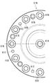
- FIGs. 9 and 10 illustrate an attachment body 610 of the drive-side attachment 61.
- the attachment body 610 has the workpiece attaching hole 61A which is formed in a core part thereof.
- the workpiece attaching hole 61A has a shape corresponding to a shape of the workpiece, which is not shown.
- Large diameter holes 61B and small diameter holes 61C are arranged on a same circle having a center at the axis of the workpiece attaching hole 61A.
- the large diameter holes 61B are the holes through which bolts (not shown) are passed for the purpose of coupling the attachment body 610 to the spindle 42.
- the small diameter holes 61C are female screws for fastening the adapter 611 to the attachment body 610 with the bolts B.
- Fig. 11 illustrates an attachment body 620 of the driven-side attachment 62.
- the workpiece attaching hole 62A is formed in a core part of the attachment body 620.
- the workpiece attaching hole 62A has a shape corresponding to the workpiece, which is not shown.
- Large diameter holes 62M are formed on a circle having a center at the axis of the workpiece attaching hole 62A.
- the large diameter holes 62M are the holes through which bolts (not shown) are passed for the purpose of coupling the attachment body 620 to the spindle 42.
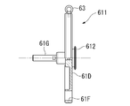
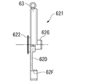
- Fig. 12A to 12C illustrate the adapters 611, 612.
- the adapter 611 of the drive-side attachment 61 has a disc part 61D which is formed in a disc-like shape, and an engagement disc 612 and a guide rod 61G which are respectively fixed to a center part of the disc part 61D.
- Insertion holes 61F continued from the large diameter holes 61B are formed in an outer peripheral region of the disc part 61D.
- a region between the center part of the disc part 61D and the outer peripheral part where the insertion holes 61F are formed has a small wall thickness.
- the attachment hanging metal fitting 63 is provided on an outer periphery of the disc part 61D.
- the guide rod 61G is passed through the workpiece attaching hole 61A in the attachment body 610.
- the adapter 621 of the driven-side attachment 62 has a disc part 62D which is formed in a disc-like shape, and an engagement disc 622 and a guide rod 62G which are respectively fixed to a center part of the disc part 62D.
- Insertion holes 62F continued from the large diameter holes 62B are formed in an outer peripheral region of the disc part 62D.
- a region between the center part of the disc part 62D and the outer peripheral part where the insertion holes 62F are formed has a small wall thickness.
- the attachment hanging metal fitting 63 is provided on an outer periphery of the disc part 62D.
- the guide rod 62G is engaged with the workpiece attaching hole 62A in the attachment body 620.
- the engagement disc 612 is disposed on a front face of the adapter 611.
- the adapter 621 has the same structure as the adapter 611.
- the adapter 611 is coupled to the attachment body 610 thereby to form the drive-side attachment 61.
- the adapter 621 is coupled to the attachment body 620 thereby to form the driven-side attachment 62.
- the attachment installing jig 10 is mounted on the base member 80 of the jig mounting member 8, and the drive-side attachment 61 is mounted on the first holding member 81, while the driven-side attachment 62 is mounted on the second holding member 82.
- a crane or the like may be used.
- the pantograph mechanism 15 is moved thereby to allow the first attachment engaging part 71 to approach the drive-side attachment 61, and the drive-side attachment 61 is set on the first attachment engaging part 71.
- the driven-side attachment 62 is set on the second attachment engaging part 72.
- the attachment installing jig 10 is operated.
- the handle is coupled to the end part of the universal joint 16, and the male screw part 21 is rotated in one direction by the universal joint 16.
- the first block 191 and the second block 192 of the pantograph mechanism 15 are separated from each other, and the first attachment engaging part 71 and the second attachment engaging part 72 are respectively retracted from the end parts of the frame 13 toward the center part thereof by means of the first link 181, the second link 182, the third link 183 and the fourth link 184.
- the drive-side attachment 61 and the driven-side attachment 62 are slid along the attachment receiving members 70F.
- the first attachment engaging part 71 which is engaged with the drive-side attachment 61 is kept stationary, and only the driven-side attachment 62 which is engaged with the second attachment engaging part 72 is retracted toward the center part of the frame 13.
- the second plate 720 of the second attachment engaging part 72 contacts the second stopper, the movement of the second attachment engaging part 72 is restricted, and the drive-side attachment 61 which is engaged with the first attachment engaging part 71 is retracted toward the center part of the frame 13.
- the first plate 710 of the first attachment engaging part 71 contacts the first stopper the drive-side attachment 61 and the driven-side attachment 62 are mounted on the attachment installing jig 10.
- the male screw part 21 is rotated in the opposite direction to the former direction, by the universal joint 16.
- the first block 191 and the second block 192 of the pantograph mechanism 15 are drawn near to each other, and the first attachment engaging part 71 and the second attachment engaging part 72 are respectively pushed out from the center part of the frame 13 toward the end parts thereof by way of the first link 181, the second link 182, the third link 183 and the fourth link 184.
- the drive-side attachment 61 which is engaged with the first attachment engaging part 71 is inserted into the spindle 42 of the drive-side holder unit 4, while sliding along the attachment receiving member 70F. Then, the drive-side attachment 61 is attached to the spindle 42.
- the adapter 611 is detached from the attachment body 610.
- the driven-side attachment 62 which is engaged with the second attachment engaging part 72 is inserted into the spindle 42 of the driven-side holder unit 5, while sliding along the attachment receiving member 70F. Then, the driven-side attachment 62 is attached to the spindle 42. Further, the adapter 621 is detached from the attachment body 620. After the drive-side attachment 61 and the driven-side attachment 62 have been respectively attached to a pair of the spindles 42, the attachment installing jig 10 is detached from the spindles 42.
- the workpiece is attached to the workpiece attaching hole 61A in the drive-side attachment 61 and the workpiece attaching hole 62A in the driven-side attachment 62, and then, the drive-side holder unit 4 and the driven-side holder unit 5 are operated. In this manner, the shaft-diameter enlargement is applied to the workpiece.
- the attachment installing jig 10 includes the attachment holding part 11 for holding the drive-side attachment 61 and the driven-side attachment 62, and the two bars 12 which are provided in the attachment holding part 11.
- the two bars 12 are allowed to come into contact with the reference parts S which are respectively formed on the circles having a center at the position at which the axes of the workpiece attaching holes 61A, 62A are set when the drive-side attachment 61 and the driven-side attachment 62 are installed in the shaft-diameter enlarging apparatus 1, and the axes of these bars 12 are positioned on the imaginary circles Q around the axes of the workpiece attaching holes 61A, 62A.
- the attachment holding part 11 includes the frame 13, the first attachment engaging part 71 which is engaged with the drive-side attachment 61, the second attachment engaging part 72 which is engaged with the driven-side attachment 62, and the retracing mechanism 15A for retracting the first attachment engaging part 71 and the second attachment engaging part 72 toward the center part of the frame 13. Therefore, it is possible to easily hold the drive-side attachment 61 and the driven-side attachment 62 in the attachment installing jig 10, by retracting the first attachment engaging part 71 and the second attachment engaging part 72 toward the center part of the frame 13 by means of the retracting mechanism 15A.
- the attachment installing jig 10 includes the push-out mechanism 15B for pushing out the first attachment engaging part 71 and the second attachment engaging part 72 toward the end parts of the frame 13. Therefore, by pushing out the drive-side attachment 61 and the driven-side attachment 62 toward the end parts of the frame 13, it is possible to easily install the drive-side attachment 61 and the driven-side attachment 62 in the shaft-diameter enlarging apparatus 1.
- the first attachment engaging part 71 and the second attachment engaging part 72 respectively have the first contact parts 701 with which the drive-side attachment 61 and the driven-side attachment 62 are contacted, when they are retracted by the retracting mechanism 15A, and the second contact parts 702 with which the drive-side attachment 61 and the driven-side attachment 62 are contacted, when they are pushed out by the push-out mechanism 15B. Therefore, it is possible to reliably move the drive-side attachment 61 and the driven-side attachment 62 back and forth.
- the first attachment engaging part 71 and the second attachment engaging part 72 are disposed at both sides of the center part of the frame 13.
- the pantograph mechanism 15 includes the first link 181 and the second link 182 which are rotatably connected to the first attachment engaging part 71 at the respective one ends thereof, the third link 183 and the fourth link 184 which are rotatably connected to the second attachment engaging part 72 at the respective one ends thereof, the first block 191 which is rotatably connected to the other end of the first link 181 and the other end of the third link 183, the second block 192 which is rotatably connected to the other end of the second link 182 and the other end of the fourth link 184, and the approaching and separating mechanism 20 for moving the first block 191 and the second block 192 toward and away from each other. Therefore, because the retracting mechanism 15A and the push-out mechanism 15B are formed of the pantograph mechanism 15 having the first link 181 to the fourth link 184, the structure of the attachment installing jig 10 can be made simple.
- the approaching and separating mechanism 20 is provided with the male screw part 21 which is respectively screwed with the first block 191 and the second block 192, a rotation amount of the male screw part 21 is proportional to moving amounts of the first block 191 and the second block 192. Therefore, it is possible to easily control a distance between the first attachment engaging part 71 and the second attachment engaging part 72.
- the handle is coupled to the end of the male screw part 21 by the universal joint 16. Therefore, even though the long-sized male screw part 21 is disposed along the vertical direction, it is possible to adjust the position of the handle, by using the universal joint 16.
- the pantograph mechanism 15 is provided on the frame 13 so as to move in parallel with the two bars 12, and the first stopper for restricting the movement of the first attachment engaging part 71 and the second stopper for restricting the movement of the second attachment engaging part 72 are respectively provided on the frame 13. Therefore, even though there is a difference in weight between the drive-side attachment 61 and the driven-side attachment 62, it is possible to reliably retract the drive-side attachment 61 and the driven-side attachment 62 toward the center part of the frame 13.
- the reference parts S are set on the outer peripheral parts of the spindles 42 which have been mounted on the shaft-diameter enlarging apparatus 1 beforehand, the installing work of the drive-side attachment 61 and the driven-side attachment 62 can be easily carried out in the shaft-diameter enlarging apparatus 1.
- Each of the bars 12 includes the columnar body 120 which is provided on the walls 131, 132 so as to move in the axial direction, the columnar engaging parts 121 which are respectively fixed to the both ends of the columnar body 120, the two fixed rings 122 which are respectively fixed to the center side of the columnar body 120, and the springs 123 which are provided between the fixed rings 122 and the walls 131, 132. Therefore, it is possible to prevent breakdown of the bar 12, when the one end of the bar 12 collides against the shaft-diameter enlarging apparatus 1 or other parts.
- the pantograph mechanism 15 is allowed to slide in a direction parallel to the axial direction of the bars 12. Therefore, the work for mounting the drive-side attachment 61 on the first attachment engaging part 71, and the work for mounting the driven-side attachment 62 on the second attachment engaging part 72 can be easily carried out.
- both the drive-side attachment 61 and the driven-side attachment 62 are held by the attachment holding part 11.
- either one of the drive-side attachment 61 and the driven-side attachment 62 may be held by the attachment holding part 11.
- the number of the bars 12 is not limited to two, but may be three or more. However, in case of providing the two bars, it is possible to easily position the drive-side attachment 61 and the driven-side attachment 62, as compared with a case of providing the three or more bars.
- the retracting mechanism 15A and the push-out mechanism 15B are incorporated in the structure of the pantograph mechanism 15.
- specific structures of the retracting mechanism 15A and the push-out mechanism 15B are not limited, but any structure can be adopted, provided that the first attachment engaging part 71 and the second attachment engaging part 72 can be moved back and forth along the axial direction of the bars 12.
- the structure may include a ball screw shaft for moving the first attachment engaging part 71 and the second attachment engaging part 72 back and forth, and a motor for rotating the ball screw shaft.
- the push-out mechanism 15B need not be necessarily provided.
- such a structure that an operator manually pushes the drive-side attachment 61 and the driven-side attachment 62 which are mounted on the attachment installing jig 10 against the spindles 42 may be adopted.
- the reference parts S are set on the outer peripheral parts R of the spindles 42.
- the reference parts S may be set in the regions which have been previously determined in the shaft-diameter enlarging apparatus 1.
- the workpiece processing machine to which the invention is applied is not limited to the shaft-diameter enlarging apparatus 1, but the invention can be applied to, for example, a machine tool for grinding a workpiece by a jig which is provided on a spindle.
Landscapes
- Engineering & Computer Science (AREA)
- Mechanical Engineering (AREA)
- Jigs For Machine Tools (AREA)
- Forging (AREA)
Abstract
L'invention concerne un gabarit (10) et un procédé pour l'installation d'un accessoire (61) dans une machine de traitement de pièces au moyen du gabarit. Le gabarit (10) comprend une partie de maintien d'accessoire (11) conçue pour maintenir l'accessoire et une pluralité de barres (12) disposées sur la partie de maintien d'accessoire (11) et agencées parallèles les unes aux autres. Les barres (12) sont conçues pour entrer en contact avec une partie de référence disposée sur un cercle présentant un centre au niveau d'une position au niveau de laquelle un axe du trou de fixation de pièce (61A) est défini lorsque l'accessoire est installé dans la machine de traitement de pièces. Un axe de chacune des barres est positionné sur un cercle présentant un centre au niveau de l'axe du trou de fixation de pièce de l'accessoire maintenu dans la partie de maintien d'accessoire.
Priority Applications (2)
| Application Number | Priority Date | Filing Date | Title |
|---|---|---|---|
| CN201680025184.4A CN107548325B (zh) | 2015-07-08 | 2016-07-08 | 配件安装夹具和配件安装方法 |
| MX2017013936A MX392015B (es) | 2015-07-08 | 2016-07-08 | Plantilla de instalación de aditamento y método de instalación de aditamento. |
Applications Claiming Priority (2)
| Application Number | Priority Date | Filing Date | Title |
|---|---|---|---|
| JP2015-137070 | 2015-07-08 | ||
| JP2015137070A JP6576717B2 (ja) | 2015-07-08 | 2015-07-08 | 金型設置用治具及び金型設置方法 |
Publications (1)
| Publication Number | Publication Date |
|---|---|
| WO2017006572A1 true WO2017006572A1 (fr) | 2017-01-12 |
Family
ID=56497820
Family Applications (1)
| Application Number | Title | Priority Date | Filing Date |
|---|---|---|---|
| PCT/JP2016/003255 Ceased WO2017006572A1 (fr) | 2015-07-08 | 2016-07-08 | Gabarit d'installation d'accessoire et procédé d'installation d'accessoire |
Country Status (4)
| Country | Link |
|---|---|
| JP (1) | JP6576717B2 (fr) |
| CN (1) | CN107548325B (fr) |
| MX (1) | MX392015B (fr) |
| WO (1) | WO2017006572A1 (fr) |
Cited By (1)
| Publication number | Priority date | Publication date | Assignee | Title |
|---|---|---|---|---|
| CN114783749A (zh) * | 2022-06-20 | 2022-07-22 | 江苏富茹电子科技集团有限公司 | 一种油浸式变压器散热油道自动化加工设备 |
Citations (4)
| Publication number | Priority date | Publication date | Assignee | Title |
|---|---|---|---|---|
| DE211219C (fr) * | ||||
| EP0571175A2 (fr) * | 1992-05-18 | 1993-11-24 | California Pellet Mill Company | Dispositif de serrage rapide pour la matrice sur une presse à granuler |
| JP2008200696A (ja) | 2007-02-19 | 2008-09-04 | Iura Co Ltd | 軸肥大加工装置 |
| EP2420332A1 (fr) * | 2010-08-20 | 2012-02-22 | OP S.r.l. | Dispositif de préhension des outils d'une presse radiale |
Family Cites Families (4)
| Publication number | Priority date | Publication date | Assignee | Title |
|---|---|---|---|---|
| FR2473917A1 (fr) * | 1980-01-21 | 1981-07-24 | Ulmic Sa | Procede et dispositif de fabrication, par filage, d'une piece presentant une partie en creux dans sa surface peripherique |
| WO2009096150A1 (fr) * | 2008-01-28 | 2009-08-06 | Pascal Engineering Corporation | Dispositif de positionnement et de fixation pour une palette de travail |
| JP2011520614A (ja) * | 2008-06-02 | 2011-07-21 | ブライトン イクイプメント コーポレイション リミテッド | ブシュ拡張装置及びブシュブランクの鍛造法 |
| CN104723239B (zh) * | 2015-03-31 | 2017-11-03 | 西峡县内燃机进排气管有限责任公司 | 涡轮增压器涡轮箱体精基准加工工艺及夹具 |
-
2015
- 2015-07-08 JP JP2015137070A patent/JP6576717B2/ja active Active
-
2016
- 2016-07-08 MX MX2017013936A patent/MX392015B/es unknown
- 2016-07-08 CN CN201680025184.4A patent/CN107548325B/zh active Active
- 2016-07-08 WO PCT/JP2016/003255 patent/WO2017006572A1/fr not_active Ceased
Patent Citations (4)
| Publication number | Priority date | Publication date | Assignee | Title |
|---|---|---|---|---|
| DE211219C (fr) * | ||||
| EP0571175A2 (fr) * | 1992-05-18 | 1993-11-24 | California Pellet Mill Company | Dispositif de serrage rapide pour la matrice sur une presse à granuler |
| JP2008200696A (ja) | 2007-02-19 | 2008-09-04 | Iura Co Ltd | 軸肥大加工装置 |
| EP2420332A1 (fr) * | 2010-08-20 | 2012-02-22 | OP S.r.l. | Dispositif de préhension des outils d'une presse radiale |
Cited By (1)
| Publication number | Priority date | Publication date | Assignee | Title |
|---|---|---|---|---|
| CN114783749A (zh) * | 2022-06-20 | 2022-07-22 | 江苏富茹电子科技集团有限公司 | 一种油浸式变压器散热油道自动化加工设备 |
Also Published As
| Publication number | Publication date |
|---|---|
| MX392015B (es) | 2025-03-21 |
| CN107548325A (zh) | 2018-01-05 |
| MX2017013936A (es) | 2018-01-15 |
| CN107548325B (zh) | 2020-06-05 |
| JP2017018975A (ja) | 2017-01-26 |
| JP6576717B2 (ja) | 2019-09-18 |
Similar Documents
| Publication | Publication Date | Title |
|---|---|---|
| US8616036B2 (en) | Machine for bending a profile in two bending directions and bending tool | |
| AU2019101619A4 (en) | A Fixed Device for Conveniently Installing Robot Arms | |
| EP3220413B1 (fr) | Installation de maintenance | |
| JP5956040B1 (ja) | 工作機械 | |
| US20210197244A9 (en) | System and method for flexible manufacturing | |
| KR20160061052A (ko) | 프로파일 가공장치 | |
| CN111515295A (zh) | 一种自动化冲孔系统及冲孔方法 | |
| US20170232564A1 (en) | Gear manufacturing machine | |
| DE102015105722B4 (de) | Automatischer Werkzeugwechsler für eine Werkzeugmaschine | |
| WO2017006572A1 (fr) | Gabarit d'installation d'accessoire et procédé d'installation d'accessoire | |
| TWI617404B (zh) | 物品保持具、搬送機器人及物品搬送方法 | |
| KR101449367B1 (ko) | 가공물 위치고정장치 | |
| EP3311936B1 (fr) | Unité de rivetage universel pour l'installation de broches de guidage sur des lamelles de stores extérieurs | |
| US6901831B2 (en) | Support fixture | |
| EP3153262A1 (fr) | Mandrin destiné à maintenir une pièce dans une machine de tournage | |
| DE102012107627A1 (de) | Modulare Werkzeugmaschine | |
| CN223761735U (zh) | 用于沿轧制轴线轧制金属杆、线或管的支架 | |
| EP0811463B1 (fr) | Palettes pour supporter des pièces et ajustement manuel des membres de support sur la palette | |
| KR101640829B1 (ko) | 유압실린더 글랜드의 가공장치 | |
| CN115870812B (zh) | 一种五轴数控机床 | |
| CN217097128U (zh) | 一种双工位转台装置 | |
| KR20170091807A (ko) | 금속 제품의 자동 가공 장치 | |
| ITTO970469A1 (it) | Attrezzaggio a cassetta per macchine di forgiatura | |
| JP5838916B2 (ja) | 切断装置及び切断装置における上刃ホルダの取外し方法 | |
| CN212145321U (zh) | 工作台及具有其的机床 |
Legal Events
| Date | Code | Title | Description |
|---|---|---|---|
| 121 | Ep: the epo has been informed by wipo that ep was designated in this application |
Ref document number: 16741399 Country of ref document: EP Kind code of ref document: A1 |
|
| WWE | Wipo information: entry into national phase |
Ref document number: MX/A/2017/013936 Country of ref document: MX |
|
| NENP | Non-entry into the national phase |
Ref country code: DE |
|
| 122 | Ep: pct application non-entry in european phase |
Ref document number: 16741399 Country of ref document: EP Kind code of ref document: A1 |