WO2017006592A1 - トラクタ - Google Patents
トラクタ Download PDFInfo
- Publication number
- WO2017006592A1 WO2017006592A1 PCT/JP2016/059064 JP2016059064W WO2017006592A1 WO 2017006592 A1 WO2017006592 A1 WO 2017006592A1 JP 2016059064 W JP2016059064 W JP 2016059064W WO 2017006592 A1 WO2017006592 A1 WO 2017006592A1
- Authority
- WO
- WIPO (PCT)
- Prior art keywords
- operation unit
- loader
- driver
- tractor
- hydraulic
- Prior art date
- Legal status (The legal status is an assumption and is not a legal conclusion. Google has not performed a legal analysis and makes no representation as to the accuracy of the status listed.)
- Ceased
Links
Images


Classifications
-
- B—PERFORMING OPERATIONS; TRANSPORTING
- B62—LAND VEHICLES FOR TRAVELLING OTHERWISE THAN ON RAILS
- B62D—MOTOR VEHICLES; TRAILERS
- B62D49/00—Tractors
- B62D49/06—Tractors adapted for multi-purpose use
- B62D49/0692—Tractors adapted for multi-purpose use characterised by the particular arrangement of control devices, e.g. having more than one control stand, operable from vehicle extension (control devices or systems characterised by mechanical features only)
-
- B—PERFORMING OPERATIONS; TRANSPORTING
- B60—VEHICLES IN GENERAL
- B60K—ARRANGEMENT OR MOUNTING OF PROPULSION UNITS OR OF TRANSMISSIONS IN VEHICLES; ARRANGEMENT OR MOUNTING OF PLURAL DIVERSE PRIME-MOVERS IN VEHICLES; AUXILIARY DRIVES FOR VEHICLES; INSTRUMENTATION OR DASHBOARDS FOR VEHICLES; ARRANGEMENTS IN CONNECTION WITH COOLING, AIR INTAKE, GAS EXHAUST OR FUEL SUPPLY OF PROPULSION UNITS IN VEHICLES
- B60K20/00—Arrangement or mounting of change-speed gearing control devices in vehicles
- B60K20/02—Arrangement or mounting of change-speed gearing control devices in vehicles of initiating means
-
- B—PERFORMING OPERATIONS; TRANSPORTING
- B62—LAND VEHICLES FOR TRAVELLING OTHERWISE THAN ON RAILS
- B62D—MOTOR VEHICLES; TRAILERS
- B62D1/00—Steering controls, i.e. means for initiating a change of direction of the vehicle
- B62D1/02—Steering controls, i.e. means for initiating a change of direction of the vehicle vehicle-mounted
- B62D1/04—Hand wheels
-
- B—PERFORMING OPERATIONS; TRANSPORTING
- B62—LAND VEHICLES FOR TRAVELLING OTHERWISE THAN ON RAILS
- B62D—MOTOR VEHICLES; TRAILERS
- B62D1/00—Steering controls, i.e. means for initiating a change of direction of the vehicle
- B62D1/02—Steering controls, i.e. means for initiating a change of direction of the vehicle vehicle-mounted
- B62D1/12—Hand levers
-
- B—PERFORMING OPERATIONS; TRANSPORTING
- B62—LAND VEHICLES FOR TRAVELLING OTHERWISE THAN ON RAILS
- B62D—MOTOR VEHICLES; TRAILERS
- B62D33/00—Superstructures for load-carrying vehicles
- B62D33/06—Drivers' cabs
- B62D33/0617—Drivers' cabs for tractors or off-the-road vehicles
-
- E—FIXED CONSTRUCTIONS
- E02—HYDRAULIC ENGINEERING; FOUNDATIONS; SOIL SHIFTING
- E02F—DREDGING; SOIL-SHIFTING
- E02F9/00—Component parts of dredgers or soil-shifting machines, not restricted to one of the kinds covered by groups E02F3/00 - E02F7/00
- E02F9/08—Superstructures; Supports for superstructures
- E02F9/0808—Improving mounting or assembling, e.g. frame elements, disposition of all the components on the superstructures
-
- E—FIXED CONSTRUCTIONS
- E02—HYDRAULIC ENGINEERING; FOUNDATIONS; SOIL SHIFTING
- E02F—DREDGING; SOIL-SHIFTING
- E02F9/00—Component parts of dredgers or soil-shifting machines, not restricted to one of the kinds covered by groups E02F3/00 - E02F7/00
- E02F9/16—Cabins, platforms, or the like, for drivers
-
- E—FIXED CONSTRUCTIONS
- E02—HYDRAULIC ENGINEERING; FOUNDATIONS; SOIL SHIFTING
- E02F—DREDGING; SOIL-SHIFTING
- E02F9/00—Component parts of dredgers or soil-shifting machines, not restricted to one of the kinds covered by groups E02F3/00 - E02F7/00
- E02F9/20—Drives; Control devices
- E02F9/2004—Control mechanisms, e.g. control levers
-
- G—PHYSICS
- G05—CONTROLLING; REGULATING
- G05G—CONTROL DEVICES OR SYSTEMS INSOFAR AS CHARACTERISED BY MECHANICAL FEATURES ONLY
- G05G1/00—Controlling members, e.g. knobs or handles; Assemblies or arrangements thereof; Indicating position of controlling members
- G05G1/01—Arrangements of two or more controlling members with respect to one another
-
- B—PERFORMING OPERATIONS; TRANSPORTING
- B60—VEHICLES IN GENERAL
- B60Y—INDEXING SCHEME RELATING TO ASPECTS CROSS-CUTTING VEHICLE TECHNOLOGY
- B60Y2200/00—Type of vehicle
- B60Y2200/20—Off-Road Vehicles
- B60Y2200/22—Agricultural vehicles
- B60Y2200/221—Tractors
-
- B—PERFORMING OPERATIONS; TRANSPORTING
- B60—VEHICLES IN GENERAL
- B60Y—INDEXING SCHEME RELATING TO ASPECTS CROSS-CUTTING VEHICLE TECHNOLOGY
- B60Y2200/00—Type of vehicle
- B60Y2200/40—Special vehicles
- B60Y2200/41—Construction vehicles, e.g. graders, excavators
- B60Y2200/415—Wheel loaders
-
- B—PERFORMING OPERATIONS; TRANSPORTING
- B62—LAND VEHICLES FOR TRAVELLING OTHERWISE THAN ON RAILS
- B62D—MOTOR VEHICLES; TRAILERS
- B62D25/00—Superstructure or monocoque structure sub-units; Parts or details thereof not otherwise provided for
- B62D25/08—Front or rear portions
- B62D25/14—Dashboards as superstructure sub-units
-
- B—PERFORMING OPERATIONS; TRANSPORTING
- B62—LAND VEHICLES FOR TRAVELLING OTHERWISE THAN ON RAILS
- B62D—MOTOR VEHICLES; TRAILERS
- B62D49/00—Tractors
Definitions
- This invention relates to an arrangement structure of various operation parts of a tractor used for farm work by connecting a work machine to the rear end.
- a tractor has a motor part mounted on the front part of the fuselage frame, a driving part is provided behind the tractor, and the PTO shaft projects from the rear end of the transmission case extending from the prime mover part along the fuselage frame.
- the tractor is connected to the rear end of the tractor body while running on the front and rear wheels provided on the axle extending from the front and rear axle cases, and farm work is carried out using the power transmitted from the PTO shaft to the work equipment. ing.
- various operation parts for the work machine are appropriately arranged on the left and right sides of the driver's seat to improve the operability by the driver (for example, see Patent Document 1).
- the operation of the various operation units may require a long operation depending on the type of work equipment and the type of work equipment to be pulled, and the operation unit is operated while operating the tractor, so that the handle is gripped.
- the various operation units must be operated while being gripped at the same time, which is an urgent issue in terms of workability and driver fatigue.
- the operation unit and the handle can be reliably gripped with different hands to improve the workability of the driver,
- a tractor that improves the workability of the driver and alleviates fatigue by arranging the main various operation parts within the range of the semicircular rotation of the right arm around the right elbow of the driver with the elbow on the armrest. I will provide it.
- the tractor according to the present invention is a tractor including a driving unit in which a loader operation unit and a hydraulic operation unit are arranged in the vicinity of a driver seat disposed behind a handle, wherein the loader operation unit and the hydraulic operation unit are It is arranged within the range of the semicircular rotation of the right arm around the right elbow of the driver with the elbow on the armrest on the right side of the driver seat.
- the bracket of the hydraulic operation unit is fixed to a fender outer peripheral surface of a fender protruding from a cabin that houses the operating unit, and the fender outer peripheral surface And at least one of the bracket of the hydraulic operation unit and the bracket of the loader operation unit are collectively covered with a guide body that supports the loader operation unit and the hydraulic operation unit. is there.
- a tractor according to another aspect of the present invention includes an accelerator-linked main shift pedal that controls the rotational speed or the vehicle speed of the engine, and the loader operation portion is provided behind the main shift pedal. is there.
- the loader operation unit and the hydraulic operation unit are By placing the right arm on the right armrest of the driver's seat within the range of the semicircular rotation of the right arm around the right elbow of the driver, the loader operation unit, hydraulic operation unit, and handle can be gripped. It can be performed reliably with different hands, and the operation of the tractor and the operation of the working machine such as towing can be clearly divided and performed in parallel. For this reason, not only can the workability be improved, but also the loader operation unit and the like can be operated with the right elbow placed on the armrest, so that fatigue during work can be greatly relieved. .
- the bracket of the hydraulic operation unit is fixed to a fender outer peripheral surface of a fender protruding from a cabin that houses the operating unit, and the fender outer peripheral surface And at least one of the bracket of the hydraulic operation unit and the bracket of the loader operation unit are collectively covered with a guide body that supports the loader operation unit and the hydraulic operation unit.
- brackets of the hydraulic operation unit and the loader operation unit can be collectively covered with the guide body without being covered with separate members, so that the assembly workability can be improved and the manufacturing cost can be kept low. Can do.
- the tractor according to another aspect of the present invention includes an accelerator-linked main shift pedal that controls the rotational speed or the vehicle speed of the engine, and the loader operation portion is provided behind the main shift pedal.
- the main shift pedal controls the rotational speed or the vehicle speed of the engine
- the loader operation portion is provided behind the main shift pedal.
- front, rear, left, and right are described with the front of the tractor viewed from the driver seated in the driver's seat as the front, the rear as the rear, the right side viewed from the driver as the right, and the left side as the left.
- a tractor has an elbow on an armrest on the right side of the driver's seat in a configuration in which a driver's seat is disposed behind the steering wheel and a loader operation unit and a hydraulic operation unit are disposed in the vicinity of the driver's seat.
- the loader operation unit and the hydraulic operation unit are arranged in the range of the semicircular rotation of the right arm around the right elbow of the driver.
- the tractor A1 as a work vehicle is centered on a body frame 1 in which a longitudinal steel plate extending in the front-rear direction is arranged in the vertical direction and arranged on the left and right. Is equipped with a prime mover section 2.
- a driving unit 3 is disposed behind the prime mover unit 2.
- Front and rear wheels FT, RT to which power is transmitted from the engine E via a mission case M are pivoted below the body frame 1.
- Mission case M is fixed to the fuselage frame 1 integrally.
- a PTO shaft (not shown) projects from the rear end of the mission case M.
- shaft is an axis
- the transmission case M is configured to be able to transmit power to various working machines connected to the rear part of the tractor A1 via a connector, a lifter or the like (not shown).
- a hydraulic continuously variable transmission, a forward / reverse switching mechanism, a sub-transmission gear mechanism, a two-wheel drive / four-wheel drive switching mechanism, a differential gear mechanism for rear wheels, and the like are provided.
- the tractor A1 is configured as a cabin-type tractor that covers the operation unit 3 with a cabin C.
- the tractor A1 is provided with a prime mover portion 2 at the front portion of the body frame 1 that is stretched in the front-rear direction to form a framework, and a transmission case M is provided at the rear end portion of the body frame 1. ing.
- the prime mover unit 2 and the transmission case M are linked to each other via a power transmission shaft (not shown).
- a front axle case FA having an axis line in the left-right direction is attached to the front portion of the body frame 1.
- Front wheels FT and FT are attached to the left and right ends of the front axle case FA via front wheel shafts (not shown).
- rear axle cases RA and RA are attached to the left and right sides of the transmission case M, respectively, and the rear wheels RT and RT are interlocked and connected to the rear axle cases RA and RA via the rear wheel shaft 4.
- the transmission case M and the front axle case FA are linked together via a front wheel drive shaft (not shown) to enable four-wheel drive for driving the front and rear wheels FT, RT.
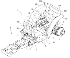
- the tractor A1 has a driving unit 3 disposed on the body frame 1 behind the prime mover unit 2. Specifically, the tractor A ⁇ b> 1 has the operation unit 3 mounted and fixed on the left and right base frames 5 attached to the sides of the body frame 1. The left and right base frames 5 have inclined frames 6 that are bent upward at the rear side. An auxiliary beam 8 is erected substantially vertically at a rear end portion of the left and right base frames 5 through a horizontal connecting plate 7 provided in association with the rear axle case RA.
- the left and right base frames 5 are mounted and fixed via vibration-proof sound plates 12 on a driving unit mounting piece 11 having a front end protruding from the side of the body frame 1.
- the lower end portion of the auxiliary beam 8 is placed and fixed via a shock absorber 218 having an anti-vibration sound plate 12 on the left and right rear axle cases RA and RA.
- the driving unit 3 has a driving unit floor 9 as a floor portion extending on the left and right base frames 5 from a position immediately after the prime mover unit 2 to a position immediately before the mission case M.
- a plan view type floor mounting plate 220 and a plan view rectangular floor reinforcing plate 221 are connected between the left and right base frames 5, and left and right steps SL configured by one piece on each of them.
- SR is placed and fixed, and a driving unit floor 9 is stretched over the upper side.
- the driver's seat frame 14 for constituting the driver's seat 13 is placed on and connected to the inclined frame 6 of the left and right base frames 5. That is, the driver's seat frame 14 includes a horizontal seat frame 15, a back frame 16 that is tilted up at the rear edge thereof, a front frame 17 that hangs below the front end of the seat frame 15, and a lower end of the front frame 17. And a dustproof plate 18 extending forward.
- the dust-proof plate 18 is connected to the rear edge of the driving unit floor 9 to block the lower part of the front end of the driver's seat frame 14 and prevent the dust rising from the ground through the space below the driver's seat 13 from entering the driving unit 3. is doing.
- a substantially triangular backing plate 19 that stands up and is in contact with the outer surface of the inclined frame 6 is in close contact with and fixed by bolts.
- a fender inner wall portion 21 of a fender 20 that covers the inner side of the rear wheel RT is inserted between the seat frame 15 and the contact plate 19 raised from the inclined frame 6 of the left and right base frames 5.
- the three members are firmly and integrally connected by bolts.
- the driver's seat 13 is disposed above the transmission case M located behind the engine E of the prime mover unit 2, and a pair of left and right fenders 20 ⁇ / b> L and 20 ⁇ / b> R are disposed on the left and right sides of the driver's seat 13.
- the pair of left and right fenders 20L and 20R are formed by being raised from the left and right sides of the rear portion of the driving unit floor 9, and cover the front upper portions of the rear wheels RT and RT.
- the pair of fenders 20L and 20R are extended with outer fenders 42L and 42R that cover the outer edges of the fenders 20L and 20R and extend outward.
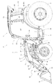
- a front loader 50 as a work machine is detachably attached to the front portion of the body frame 1.
- the front loader 50 includes a pair of left and right masts 51 that are detachably attached to the body frame 1, a pair of left and right lift arms 52 that are connected to the mast 51 so as to be vertically rotatable, and a connection that connects the pair of left and right lift arms 52.
- Pipe 53 a pair of left and right work tool links 54, a pair of left and right work tool brackets 55, a work tool 56 attached to a pair of left and right lift arms 52, a pair of left and right arm cylinders 57, and a pair of left and right work tools A cylinder 58, a stand 59, and a front guard that protects the front portion of the tractor A1 are provided.
- the front loader 50 performs work by raising and lowering the work tool 56.
- a bucket is used as the work tool 56, but other work tools can be attached.
- a pair of left and right loader mounts 60 are respectively fixed to the outside of the left and right plate-like members constituting the machine body frame 1.
- a pair of left and right masts 51 are detachably attached to the pair of left and right loader mounts 60.
- the lift arm 52 is configured to have a boomerang-like shape in a side view of the machine body by a rear lift arm 52 a attached to the mast 51 and a front lift arm 52 b attached to the work tool 56.
- the rear lift arm 52a and the front lift arm 52b are fixed to each other by welding so as to form a predetermined angle.
- the rear ends of the left and right lift arms 52 are pivotally supported by pivot shafts 61 at the upper end of the mast 51, respectively.
- the front loader 50 is configured such that the front portion can be turned up and down around the pair of left and right pivot shafts 61.
- a front end portion (rear end) of the piston rod of the arm cylinder 57 is pivotally supported at the front end portion of the mast 51 in the middle of the upper and lower parts, and an arm cylinder bracket portion below the front end portion of the rear lift arm 52a includes A base end portion (front end) of the arm cylinder 57 is pivotally supported.
- the pair of left and right arm cylinders 57 serve as an actuator for turning the front loader 50 up and down, and by the simultaneous expansion and contraction of the piston rods of the left and right arm cylinders 57, the vertical turning angle of the front loader 50, that is, The angle of the pair of left and right lift arms 52 with respect to the mast 51 is adjusted.
- the left and right front lift arms 52b are integrally fixed by connecting the front and rear intermediate portions thereof with each other by a connection pipe 53 whose longitudinal direction is the body width direction.
- the front end of the front lift arm 52 b is attached to the work tool 56 via the work tool bracket 55.
- the work tool bracket 55 pivotally supports the front end of the front lift arm 52b. Thereby, the work tool bracket 55 and the work tool 56 can be rotated up and down with respect to the pair of left and right lift arms 52.
- Each work tool link 54 includes an arm side link member 54a and a work tool side link member 54b.
- the lower end of the arm side link member 54a is pivotally supported by the front and rear midway part of the front lift arm 52b.
- the lower end of the work tool side link member 54 b is pivotally supported on the upper part of the work tool bracket 55.
- a work tool cylinder 58 is attached above the front end of the lift arm 52.
- the upper ends of the arm-side link member 54a and the work tool-side link member 54b pivotally support the tip of the piston rod of the work tool cylinder 58.
- the base end portion of the work tool cylinder 58 is pivotally supported above the front end portion of the rear lift arm 52a.
- the pair of left and right work tool cylinders 58 serves as actuators for pivoting the work tool bracket 55 back and forth.
- the angle formed by the arm side link member 54a and the work tool side link member 54b is adjusted, the front / rear rotation angle of the work tool bracket 55 with respect to the lift arm 52 is adjusted, and the rotation angle of the work tool 56 is adjusted.
- the hydraulic operation unit 30 for switching the operation (not shown), other operation levers 330 and 332, and switches 331 are provided.
- a hot air shielding plate 200 that shields the prime mover unit 2 and the operating unit 3 is erected on the front edge of the operating unit floor 9.
- a connecting case 27 protrudes from the hot air shielding plate 200 on the side of the operating unit 3, and is further attached to a steering column 24 attached to a steering bracket 28 fixed to the connecting case 27 in a tiltable manner via a handle support shaft 26. H is provided.
- the dashboard 25 is attached to the upper edge of the hot air shielding plate 200 at the front upper side of the steering column 24, and the steering mechanism 22 is covered with a steering cover 43 except for the steering wheel H.
- An accelerator lever 65 for setting and maintaining the rotational speed of the engine E is provided on the right side of the steering cover 43.
- the various operation pedals 23 are supported by a connection case 27 protruding from the hot air shielding plate 200, and a clutch pedal CP, a left brake pedal LBP, and a right brake pedal RBP are arranged from the left.
- An accelerator pedal AP projects from the right step SR that constitutes the floor surface.
- the accelerator pedal AP functions as an accelerator-linked main transmission pedal that controls the rotational speed of the engine E or the vehicle speed.
- a potentiometer (variable resistor) type pedal sensor for detecting the vertical movement of the accelerator pedal AP is fixed below the right step SR.
- the floor surface is a generally flat surface.
- a driver seat 13 having left and right armrests 300L and 300R is placed on the horizontal seat frame 15 formed on the driver seat frame 14, as shown in FIGS. 10 and 11.
- the loader operation unit 29, the hydraulic operation unit 30, other various operation levers 330 and 332, and switches 331 are intensively arranged, and are easy for the driver to operate.
- the cabin C includes a cabin frame 222 that is framed so as to form a hexahedron, and respective surface portions 223, 225, which are formed by pieces that form the cabin frame 222. 231 and 236.
- the cabin frame 222 has a ceiling portion 224 formed in a flat box shape on the ceiling surface portion 223, a front glass portion 226 is stretched on the upper portion of the front portion 225, and a left and right front wall portion 227 is formed on the lower portion. It is stretched.
- the hot air shielding plate 200 constitutes a part of the front portion 225 of the cabin C. That is, the front portion 225 is configured by the hot air shielding plate 200, the left and right front wall portions 227 that are stretched on the left and right sides of the hot air shielding plate 200, and the windshield portion 226 that is stretched on the hot air shielding plate 200.
- the rear surface portion 231 has the upper end of the auxiliary beam 8 connected integrally with the rear end of the fender 20 and the rear lower end of the cabin frame 222 via the connection bracket 233.
- the rear lateral frame 232 provided in the middle stage of the rear surface of the cabin frame 222 is integrally connected to the back frame 16 of the driver's seat frame 14 by bolts.
- the front lower end edge of the cabin frame 222 that is, the horizontal lower frame 235 in front of the semicircular frame 234 placed on the fender 20, is in contact with the outer edge of step S as shown in FIGS. They are in contact with each other.
- a pair of left and right entrance / exit door portions 237 and 237 are stretched on the front portion of the left and right side surface portions 236 so as to be freely opened and closed. As shown in FIG. 11, an opening / closing operation grip 239 is provided outside the passenger door portion 237. A grip pipe 238 is stretched on the inner surface of the passenger door 237.
- a pair of left and right side window portions 240 are stretched on the rear portion of the left and right side surface portions 236 so as to be freely opened and closed.
- a rear glass portion 241 is stretched on the rear surface portion 231 so as to be freely opened and closed.
- the prime mover section 2 is configured by disposing an engine E or the like at the front of the body frame 1.
- a cooling fan 31 and a radiator 32 are erected immediately in front of the engine E.
- the motor unit 2 configured as described above is provided with a bonnet support frame (not shown), and the bonnet B is attached to the bonnet support frame so as to be opened and closed.
- the engine room of the motor unit 2 is covered with the bonnet B. It is open.
- the bonnet B is a box that opens downward and rearward from a ceiling surface portion 33 formed in an inverted shape (so-called ship bottom ceiling), a mesh-shaped front grille 34, and left and right side surface portions 35, 35. It is formed into a mold.
- an exhaust heat cover 37 having an exhaust heat hole 38 is formed in the gap 36 formed between the bonnet B covering the prime mover unit 2 configured as described above and the operating unit 3. Is installed.
- the exhaust heat cover 37 is connected to the upper portion of the hot air shielding plate 200.
- the tractor A1 according to the embodiment of the present invention has the basic structure as described above.
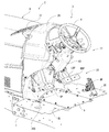
- the operating unit 3 of the tractor A1 has the following configuration. That is, in the tractor driving section 3 in which the driver's seat 13 is disposed behind the steering wheel H and the loader operating section 29 and the hydraulic operating section 30 are disposed in the vicinity of the driver's seat 13, as shown in FIG.
- the loader operation unit 29 and the hydraulic operation unit 30 are arranged in the range of the semicircular rotation of the right arm around the driver's right elbow on the armrest 300R.
- the loader operation unit 29 and the hydraulic operation unit 30 move the right elbow attached to the armrest 300R in a state where the driver sitting in the driver's seat 13 places the right elbow at a predetermined position on the armrest 300R. And is provided within a range that can be operated with the right hand.
- the hydraulic operation bracket 310 which is a bracket of the hydraulic operation unit 30 is fixed to the fender outer peripheral surface 302 of the fender 20 protruding in the cabin C that houses the operation unit 3 as shown in FIG.
- the fender outer peripheral surface 302 of the fender 20, the hydraulic operation bracket 310, and the loader operation bracket 307, which is a loader operation unit 29 bracket, are configured to be collectively covered with a guide body 303 that supports the operation units 29 and 30. It also has a feature.
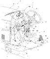
- the driving unit 3 has a handle H in front of the driver's seat 13 and includes a display device (not shown) installed in the dashboard 25 in front of the handle H. .
- Various instruments are disposed in the display device.
- Various operation pedals 23 are arranged above the floor surface below the handle H.
- fenders 20L and 20R As shown in FIG.
- a loader operation unit 29 for performing the lifting operation of the work implement On the right fender 20R, that is, on the fender outer peripheral surface 302 and in the vicinity thereof, a loader operation unit 29 for performing the lifting operation of the work implement, a hydraulic operation unit 30 for performing operations related to hydraulic pressure, and other operation levers 330 and 332 and switches 331 are disposed. Further, the loader operation unit 29 and the hydraulic operation unit 30 are disposed around the right armrest 300R so as to be positioned on the semicircular locus T in plan view (see FIG. 10).
- the loader operation section 29 and the hydraulic operation section 30 are arranged such that the height positions of the respective front end portions are slightly above the upper surface of the right armrest 300R and are substantially the same height position. Yes.
- the loader operation unit 29 is provided behind the accelerator pedal AP.
- the hydraulic operation unit 30 is provided behind the loader operation unit 29.
- the loader operation unit 29 includes a rod-shaped loader operation lever body 304 and a gripping unit including various operation switches (305a, 305b, 305c) capable of mode switching at the tip of the loader operation lever body 304. 306 and configured as an integral loader lever.
- a loader operation bracket 307 is fixed on the seat frame 15 located between the front right side of the driver seat 13 and the fender 20R, that is, between the driver seat 13 and the fender 20R.
- the loader operation bracket 307 is mainly composed of a rectangular plate-like member having an approximately L shape.
- the loader operation part 29 is erected so that the base part is connected to a loader operation bracket 307 and can be swung freely. Note that the loader operation unit 29 may be disposed on the outer peripheral surface of the right fender 20R.
- the loader operation unit 29 is a lever operation unit for switching a loader valve (not shown) for controlling supply of hydraulic oil to the hydraulic equipment of the front loader 50.
- the loader valve is provided on the side surface of the body frame 1 via a bracket or the like.
- a loader operation lever body 304 of the loader operation unit 29 is swingably supported by the loader operation bracket 307.
- the loader operation unit 29 is connected to the loader valve via push-pull wires 63 and 64 that are connected and fixed to the loader operation bracket 307 via a link member or the like.
- the tip of one push-pull wire 63 is connected to a link member for tilting left and right.
- the link member for tilting left and right is supported by the loader operation bracket 307 so as to be swingable in the left and right directions in accordance with the left and right tilting operation of the loader operation unit 29.
- the tip of the push-pull wire 63 moves up and down via the link member for tilting left and right.
- the tip of the other push-pull wire 64 is connected to a link member for tilting back and forth.
- the link member for forward / backward tilting is supported by the loader operation bracket 307 so as to be swingable in the front / rear direction in accordance with the forward / backward tilting operation of the loader operation unit 29.
- the tip of the push-pull wire 64 moves up and down via the link member for tilting back and forth.
- an operation lever 330 that is inserted from below a long hole 308 formed in the seat frame 15 with the front-rear direction as a longitudinal direction and protrudes upward is disposed.
- the operation lever 330 is a separate operation unit with a relatively high operation frequency.
- the height of the tip of the operation lever 330 is lower than the right armrest 300R as shown in FIGS.
- the operation lever 330 is a working part position lever that changes and adjusts the height position of a ground working machine such as a rotary tiller.
- a hydraulic operation unit 30 is disposed near the upper rear end of the fender 20R on the right side of the driver's seat 13.
- the hydraulic operation unit 30 is provided with three hydraulic operation levers (SCV levers) 309 for switching the hydraulic external take-off valve.
- Each hydraulic operation lever 309 is rod-shaped and has a grip at the tip.
- the three hydraulic operation levers 309 are disposed adjacent to the front and rear.
- the hydraulic external take-off valve is used to supply and control hydraulic oil to hydraulic equipment of a working machine such as a rotary tiller or a component caster that is retrofitted to the tractor A1.
- the number of hydraulic operation levers 309 is arranged according to the number of hydraulic external extraction valves. That is, in this embodiment, three hydraulic external take-off valves are provided.
- each hydraulic operation lever 309 is connected to a hydraulic operation bracket 310 as shown in FIG.
- the hydraulic operation bracket 310 is mainly composed of a rectangular plate-like member that is bent and fixed along the fender 20R on the fender outer peripheral surface 302 of the right fender 20R.
- Each hydraulic operation lever 309 disposed in the hydraulic operation unit 30 is connected to the hydraulic operation bracket 310 at its base and is erected so as to be operated.
- a switch 331 such as a mode changeover switch connected to a guide body 303 described later is disposed above the front portion of the hydraulic operation bracket 310.
- a PTO clutch switch 331a, a rotation speed / vehicle speed setting dial 331b, a rotation speed / vehicle speed selection switch 331c, and a vehicle speed sensitivity adjustment dial 331d are disposed as the switches 331 (see FIG. 12).
- the PTO clutch switch 331a is an operation unit for performing intermittent operation of power transmission from the PTO shaft to a work machine such as a rotary tiller.
- the rotation speed / vehicle speed setting dial 331b is an operation unit for presetting the maximum rotation speed of the engine E or the maximum traveling speed of the body frame 1.
- the rotational speed / vehicle speed selection switch 331c is an operation unit for designating whether the value set by the rotational speed / vehicle speed setting dial 331b is the maximum rotational speed of the engine E or the maximum traveling speed of the body frame 1.
- the vehicle speed sensitivity adjustment dial 331d is an operation unit for adjusting the acceleration / deceleration of the vehicle speed when the accelerator pedal AP is operated.
- an engine tilt switch 305a is provided on the front surface of the grip unit 306, and a valve operation switch 305b and a mode switch 305c are provided on the left side surface of the grip unit 306. Since the grip portion 306 is gripped by the operator's right hand, the engine tilt switch 305a is disposed at a position where it can be operated with an index finger or the like, and a valve operation switch 305b and a mode switch 305c are disposed at a position where the thumb can be operated. ing. Therefore, the operator can easily operate the switches 305a, 305b, and 305c while holding the loader operation unit 29 during the loader work by the front loader 50.
- the engine tilt switch 305a is used, for example, when a high load is applied during execution of a tilting operation using a front loader 50 or a dozer operation for scratching the ground.
- the engine rotation speed of the engine E is increased, while the gear ratio by the hydraulic continuously variable transmission is decreased to execute engine tilt control that keeps the vehicle speed of the tractor A1 constant.
- the engine tilt control is a case where the first speed and the second speed are designated among the sub-speeds that can be designated up to the third speed by the sub-shift lever, and the mode change control by the mode change switch 305c is not executed. It is executed while the engine tilt switch 305a is pressed.
- the operator determines that the work is a high load operation based on hearing and vision during the loader operation by the front loader 50, and simultaneously operates the loader operation unit 29.
- the engine tilt control is easily executed with the hand (right hand in this embodiment).
- the hydraulic lift for the arm cylinder 57 and the work tool cylinder 58 can be increased instantaneously according to the operator's judgment, so that the complexity of operating the work machine such as the front loader 50 can be increased.
- the load on the work machine can be reduced.
- the valve operation switch 305b is a hydraulic cylinder other than the arm cylinder 57 and the work tool cylinder 58. Used in the configuration provided in the work tool 56.
- the bale grab cylinder in the bale grab serving as the work tool 56 expands and contracts, and the pasture roll can be held or released.
- the arm cylinder 57 is operated by the forward / backward tilting operation of the loader operation unit 29 and the work tool 56 is moved up and down, and the work tool cylinder 58 is operated by the left / right tilting operation of the loader operation unit 29 to perform work.
- the bale grab serving as the tool 56 is tilted up and down, and the valve operation switch 305b of the loader operation unit 29 is operated to operate the bale grab cylinder to open and close the bale grab serving as the work tool 56.
- the mode switch 305c is used when switching between the maximum rotation speed and the maximum speed set in advance for a plurality of modes. Although the present embodiment will be described as the case of the two modes of the first mode and the second mode, it is possible that settings of three or more modes can be executed.
- the maximum rotation speed and the maximum vehicle speed in the first and second modes are set by operating the rotation speed / vehicle speed setting dial 331b and the rotation speed / vehicle speed selection switch 331c serving as a rotation speed / vehicle speed setting operation tool. Note that the rotational speed of the engine E and the vehicle speed of the tractor A1 at the maximum positions of the accelerator lever 65 and the accelerator pedal AP are set as the maximum rotational speed and the maximum vehicle speed set in the first and second modes, respectively.
- the mode switching switch 305c By operating the mode switching switch 305c, switching between the first mode and the second mode is executed, and the maximum rotation speed and the maximum vehicle speed in the first and second modes are switched according to the operation to the mode switching switch 305c. .
- the maximum rotation speed and the maximum vehicle speed in the second mode are set to be smaller than the maximum rotation speed and the maximum vehicle speed in the first mode.
- the mode changeover switch 305c is operated to set the second.
- the tractor A1 is moved at a low speed, so that the object to be transported can be prevented from dropping.
- the mode changeover switch 305c is operated to switch to the first mode, so that the tractor A1 is moved at a high speed, so the travel time from the carry-out destination to the carry-in source is shortened. It is possible to improve work efficiency.
- the operator By disposing the mode changeover switch 305c in the loader operation unit 29, the operator operates the loader operation unit 29 based on the presence or absence of the object to be transported during the transport operation by the front loader 50 (this embodiment). In the right hand), the moving speed of the tractor A1 is easily switched. Therefore, when the transport object is transported by the front loader 50, the transport object can be prevented from falling, and the travel time can be shortened when the transport object is moved after the transport is completed, so that the work efficiency can be improved.
- accelerator interlock control is performed as operation control related to the accelerator pedal AP.
- accelerator-linked control the vehicle speed when only the accelerator pedal AP is at the maximum position is set as the maximum vehicle speed set for each mode.
- accelerator interlocking control is not executed, the vehicle speed when the accelerator pedal AP and the accelerator lever 65 are set to the maximum positions is set as the maximum vehicle speed set for each mode.
- the vehicle speed of the tractor A1 is changed according to the depression amount of the accelerator pedal AP, and the rotation speed of the engine E is changed from the minimum rotation speed set by the accelerator lever 65.
- the rotation speed of the engine E increases and the vehicle speed of the tractor A1 increases.
- the accelerator interlocking control is not executed, the tractor A1 is kept in a state where the rotational speed of the engine E is kept constant at the minimum rotational speed set by the accelerator lever 65 according to the depression amount of the accelerator pedal AP. The vehicle speed changes.
- the switch for executing the accelerator interlocking control is disposed on the upper surface of the steering column 24, for example.
- the various operation units such as the loader operation unit 29 and the hydraulic operation unit 30 arranged as described above include the brackets 307 and 310 and the fender 20R exposed to the operation unit 3 in FIG.
- the guide body 303 shown is collectively covered.
- the guide body 303 is colored differently from the peripheral member adjacent to the guide body 303. Thereby, it is easy to visually recognize that the region where various operation units such as the loader operation unit 29 and the hydraulic operation unit 30 are disposed is a region where an operation different from the handle H operation is performed.
- an operating lever 332 that is inserted from below 315 and protrudes upward is provided.
- the operation lever 332 is a separate operation unit that is less frequently operated.
- an auxiliary transmission lever that switches the output range of the traveling auxiliary transmission gear mechanism provided in the transmission case M, and a four-wheel drive lever that switches between the two-wheel drive and the four-wheel drive of the front and rear wheels FT, RT are arranged.
- the guide body 303 is formed in a concave substantially curved shape with the lower side as the open side, and a part of the upper part and the side part of the fender 20R of the fender 20R are located upward. It is a member that can be covered.
- a loader operation lever insertion hole 318 that penetrates the loader operation lever body 304 of the loader operation section 29 is formed so as to penetrate therethrough. That is, in the guide body 303, the portion where the loader operation lever insertion hole 318 is formed is a portion that is erected upward from the floor surface of the operation unit floor 9 and has an opening in the upper and lower ends. Forming.
- a rectangular box-shaped switch mounting portion 319 is installed in the middle of the upper portion of the guide body 303 so as to operably mount various switches 331 and the like to cover the mechanism portion.
- a plurality of switch attachment holes 320 are formed in the switch attachment portion 319 so that each operation portion of the switch 331 is exposed from the surface.
- a hydraulic operation lever insertion elongated hole 321 for inserting the hydraulic operation lever 309 of the hydraulic operation unit 30 is formed on the upper rear end side of the guide body 303.
- the hydraulic operation lever insertion long hole 321 is formed such that its longitudinal direction forms an inclination angle of about 45 ° with respect to the front-rear direction in plan view and is obliquely forward from the inner side to the outer side in the vehicle left-right direction.
- the three hydraulic operation lever insertion long holes 321 are formed in parallel to each other adjacent to the front and rear.
- a lever insertion long hole 322 for inserting the operation lever 330 is formed in the middle portion of the side portion of the guide body 303.
- the lever insertion long hole 322 is a guide hole whose longitudinal direction is the front-rear direction in plan view.
- the lever insertion long hole 322 is formed at a position lower than the loader operation lever insertion hole 318, the switch attachment hole 320, and the hydraulic operation lever insertion long hole 321 described above.
- the guide body 303 of the present embodiment is formed as described above, the exposed portion of the fender 20R that is not covered with the guide body 303 may be covered with a separate fender cover (not shown).
- the loader operation unit 29 is positioned slightly to the right in front of the right armrest 300R in plan view.
- the hydraulic operation unit 30 is located on the right side of the right armrest 300R in a plan view so as to be curved outward from the middle part to the rear end part of the right armrest 300R.
- the locus in plan view connecting the loader operation portion 29 and the hydraulic operation portion 30 is located on the semicircular locus L as shown in FIG. Specifically, the arcuate trajectory (T) in plan view passes through the operation movement range of the loader lever as the loader operation unit 29 and the operation movement range of each hydraulic operation lever 309 of the hydraulic operation unit 30. In this way, the loader operation unit 29 and the hydraulic operation unit 30 are arranged so that any operation position in the operation movement range of each operation unit (lever) is positioned on the arcuate trajectory (T) in plan view. Has been.
- a loader operation unit 29 is provided substantially in front of the right armrest 300R (see arrow D1), and the hydraulic operation unit 30 is located in a direction substantially perpendicular to the right direction (see arrow D2). Is provided.
- An operation lever having substantially the same height as that of the loader operation unit 29 or the like is not provided in the 45 ° diagonally right area of the right armrest 300R. Switches 331 are provided.
- the separate operation lever 330 having a relatively high operation frequency disposed in the 45 ° diagonally right region of the right armrest 300R where the loader operation unit 29 and the hydraulic operation unit 30 are not located has a tip portion height.
- the operation units 29 and 30 are clearly separated in terms of arrangement, including the fact that the operation units 29 and 30 are clearly lower than the operation units 29 and 30.
- the tractor A1 includes an accelerator-linked accelerator pedal AP that controls the rotational speed or the vehicle speed of the engine E, and the loader operation unit 29 is provided behind the accelerator pedal AP.
- the rotational speed or the vehicle speed of the engine E is controlled by the pedal operation of the accelerator pedal AP without providing a manually operated operation member such as a main transmission lever as an operation member for main transmission. Is possible.
- the operation object by manual operation can be reduced, the workability at the time of operation of the loader operation unit 29 can be improved, and the work burden on the driver when operating the loader operation unit 29 is reduced. be able to.
- the loader operation unit 29 can be disposed at the tip of the right armrest 300R ′ as in the modification examples shown in FIGS.
- the loader operation portion 29 of this modification can be tilted forward and backward at the distal end portion of the lever support portion 401 extending integrally forward with the right armrest 300R ′ on the distal end side of the right armrest 300R ′.
- the loader operation lever body 402 is supported by the robot.
- the lever support portion 401 includes support side wall portions 401a that face each other in the left-right direction.
- a loader operation lever body 402 is supported between the left and right support side wall portions 401a with the left-right direction as the rotation axis direction.
- the loader operation lever body 402 extends upward (in detail, obliquely forward upward) from the front end portion of the lever support portion 401.
- the loader operation unit 29 is connected to the loader valve via the two push-pull wires.
- rotation operation switches 403 and 404 for rotating the work tool 56 of the front loader 50 are provided at two locations along the longitudinal direction of the loader operation lever body 402. It has been.
- the rotation operation switches 403 and 404 are button-type switches that are pressed. By pressing the upper rotation operation switch 403, the work tool 56 is rotated to one side (upward), and by pressing the lower rotation operation switch 404, the work tool 56 is moved to the other side (lower). To turn.
- the arm valve in the loader valve acts when one of the two push-pull wires pushes and pulls in response to the forward / backward tilting operation of the loader operation lever body 402.
- the arm cylinder 57 is extended and retracted, the left and right lift arms 52 are turned up and down, and the work tool 56 is moved up and down.
- the other push-pull wire of the two push-pull wires pushes and pulls in response to the pressing operation of any one of the rotation operation switches 403 and 404 on the side surface of the loader operation lever body 402, so that the loader The work implement valve in the valve acts.
- the work tool cylinder 58 is extended and retracted in the front loader 50 and the work tool 56 is rotated.
- a lifting lever 405 for finely adjusting the lifting / lowering of the work tool 56 with respect to the lifting / lowering operation of the work tool 56 of the front loader 50 is projected.
- the elevating lever 405 is a knob type lever that moves up and down with respect to the loader operation lever body 402. By moving the lifting lever 405 upward, the work tool 56 is moved up by a small amount by the operation of the arm cylinder 57, and by moving the lifting lever 405 downward, the work tool 56 is moved by the operation of the arm cylinder 57. Decrease by small amount.
- a switch disposition surface portion 401b is provided behind the loader operation lever body 402 in the lever support portion 401, and switches 406 are disposed on the switch disposition surface portion 401b.
- switches 406 for example, the above-described rotation speed / vehicle speed setting dial, rotation speed / vehicle speed selection switch, and the like are arranged.
- the loader operation unit 29 is substantially in front of the right armrest 300R ′ (see arrow D1), and the hydraulic operation unit 30 is also substantially perpendicular to the right direction of the armrest 300R ′. Is disposed at a position in a direction (see arrow D2).
- the hydraulic operation lever 309 of the hydraulic operation unit 30 is composed of two, but the number of hydraulic operation levers 309 is a number that matches the number of hydraulic external take-off valves as described above. It is not limited to this embodiment.
- FIG. 19 shows a state in which the hydraulic operation lever 309 is erected on the fender 20R via the hydraulic operation bracket 310 ′ according to this modification
- FIG. 20 shows the guide body 303 ′ according to this modification
- FIG. 21 shows a cover body 334 for covering the exposed portion of the fender 20R that is not covered with the guide body 303 ′
- FIG. 22 shows a state in which a part of the fender 20R is covered with the cover body 334.
- the tractor A1 has a driver's seat 13 behind the steering wheel H and a driver 3 having a loader operating portion 29 and a hydraulic operating portion 30 in the vicinity of the driver's seat 13.
- the loader operation unit 29 and the hydraulic operation unit 30 are disposed within the range of the semicircular rotation of the right arm around the right elbow of the driver with the elbow on the armrest 300R on the right side of the driver's seat 13. Is provided.
- the loader operation unit 29, the hydraulic operation unit 30, and the handle H can be reliably gripped with different hands, and the operation of the tractor A1 and operation of the work machine such as towing can be performed. It can be done clearly in parallel. For this reason, not only can the workability be improved, but also the loader operation unit 29 and the like can be operated with the right elbow placed on the armrest 300R, so that the fatigue during the work can be greatly reduced. Can do.
- an operation unit other than the loader operation unit 29 and the hydraulic operation unit 30 can be arranged within the range of the semicircular arc rotation of the right arm, the workability can be further improved.
- the hydraulic operation bracket 310 that is a bracket of the hydraulic operation unit 30 is fixed to the fender outer peripheral surface 302 of the fender 20 protruding in the cabin C that houses the operation unit 3.
- the tractor A1 is configured to collectively cover the fender outer peripheral surface 302 of the fender 20R and the brackets 307 and 310 of the operation units 29 and 30 with a guide body 303 that supports the operation units 29 and 30. ing.
- the loader operation unit 29 and the hydraulic operation unit 30 can be collectively covered with the guide body 303 without covering the brackets 307 and 310 with separate members, the assembly workability can be improved and the manufacturing cost can be improved. Can be kept low.
- the loader operation bracket 307 and the hydraulic operation bracket 310 corresponding to the loader operation unit 29 and the hydraulic operation unit 30 are provided, and the hydraulic operation bracket 310 is fixed to the fender outer peripheral surface 302.
- a configuration in which the brackets 307 and 310 and the fender outer peripheral surface 302 are collectively covered with a guide body 303 is employed.
- the covering configuration by the guide body 303 is not limited to the above configuration, and one of the loader operation bracket 307 and the hydraulic operation bracket 310, for example, as shown in a modified example.
- a configuration in which the guide body 303 and the fender outer peripheral surface 302 are collectively covered may be employed.
Landscapes
- Engineering & Computer Science (AREA)
- Chemical & Material Sciences (AREA)
- Combustion & Propulsion (AREA)
- Transportation (AREA)
- Mechanical Engineering (AREA)
- Mining & Mineral Resources (AREA)
- Civil Engineering (AREA)
- General Engineering & Computer Science (AREA)
- Structural Engineering (AREA)
- General Physics & Mathematics (AREA)
- Automation & Control Theory (AREA)
- Physics & Mathematics (AREA)
- Lifting Devices For Agricultural Implements (AREA)
- Motor Power Transmission Devices (AREA)
- Retarders (AREA)
- Mechanical Control Devices (AREA)
- Component Parts Of Construction Machinery (AREA)
- Body Structure For Vehicles (AREA)
Abstract
主要な各種操作部を運転者の右側に配置することで操作部とハンドルの夫々の把持を異なる側の手で確実に行えるようにして運転者の作業性の向上を図ると共に、主要な各種操作部をアームレスト上に肘付した運転者の右肘を中心に右腕の半円弧回動の範囲内に配置したことで運転者の作業性の向上と疲労緩和を可能にするトラクタを提供する。 ハンドルの後方に配置された運転席の近傍にローダ操作部と油圧操作部とを配置した運転部を備えたトラクタにおいて、前記ローダ操作部及び前記油圧操作部を、前記運転席の右側のアームレスト上に肘付きした運転者の右肘を中心に右腕の半円弧回動の範囲内に配置した。
Description
この発明は、後端に作業機を連結して農作業を行うために使用するトラクタの各種操作部の配置構造に関する。
従来、トラクタは機体フレームの前部に原動機部を搭載し、その後方に運転部を設け、機体フレームに沿って原動機部から延設したミッションケース後端にPTO軸を突出すると共に、機体フレーム下方の前後のアクスルケースより延出した車軸に設けた前後車輪により走行しながらトラクタ本体の後端に連結した作業機を牽引してPTO軸から作業機に伝達した動力により農作業を行うように構成している。
運転部においては作業機のための各種操作部を運転席の左右側に適宜配置し、運転者による操作性の向上を図っている(例えば、特許文献1参照)。
かかるトラクタにおいては、運転席の左右側に各種操作部を配置することで運転席前方に位置するハンドルよるトラクタの運転を阻害することなく、各種操作部を操作することができる。
しかしながら、各種操作部の操作は、作業の内容や牽引等する作業機の種類によって長時間に渡る操作が必要な場合があり、しかも、操作部の操作はトラクタを運転しながら行うためハンドルの把持と共に各種操作部も同時に把持しながら操作しなければならず、作業性や運転者の疲労の面で喫緊の課題であった。
この発明では、主要な各種操作部を運転者の右側に配置することで操作部とハンドルの夫々の把持を異なる側の手で確実に行えるようにして運転者の作業性の向上を図ると共に、主要な各種操作部をアームレスト上に肘付した運転者の右肘を中心に右腕の半円弧回動の範囲内に配置したことで運転者の作業性の向上と疲労緩和を可能にするトラクタを提供せんとする。
本発明に係るトラクタは、ハンドルの後方に配置された運転席の近傍にローダ操作部と油圧操作部とを配置した運転部を備えたトラクタにおいて、前記ローダ操作部及び前記油圧操作部を、前記運転席の右側のアームレスト上に肘付きした運転者の右肘を中心に右腕の半円弧回動の範囲内に配置したものである。
また、本発明の他の態様に係るトラクタは、前記油圧操作部のブラケットは、前記運転部を収納するキャビン内に突設されたフェンダのフェンダ外周面に固設されており、前記フェンダ外周面と前記油圧操作部のブラケット及び前記ローダ操作部のブラケットの少なくともいずれか一方のブラケットとを、前記ローダ操作部及び前記油圧操作部を支持するガイド体で一括して被覆するように構成したものである。
また、本発明の他の態様に係るトラクタは、エンジンの回転速度または車速を制御するアクセル連動の主変速ペダルを備え、前記ローダ操作部は、前記主変速ペダルの後方に設けられているものである。
本発明に係るトラクタよれば、ハンドルの後方に配置された運転席の近傍にローダ操作部と油圧操作部とを配置した運転部を備えたトラクタにおいて、前記ローダ操作部及び前記油圧操作部を、前記運転席の右側のアームレスト上に肘付きした運転者の右肘を中心に右腕の半円弧回動の範囲内に配置したことにより、ローダ操作部や油圧操作部と、ハンドルの夫々の把持を異なる側の手で確実に行うことができ、トラクタの運転と牽引等する作業機の操作等を明確に分けて並行しておこなうことができる。このため、作業性の向上を図ることができるばかりでなく、アームレスト上に右肘を載置した状態でローダ操作部等を操作することができるため作業時の疲労を大幅に緩和することができる。
また、右腕の半円弧回動の範囲内にはローダ操作部や油圧操作部以外の操作部も配置することができるため、更なる作業性の向上を図ることができる。
本発明の他の態様に係るトラクタによれば、前記油圧操作部のブラケットは、前記運転部を収納するキャビン内に突設されたフェンダのフェンダ外周面に固設されており、前記フェンダ外周面と前記油圧操作部のブラケット及び前記ローダ操作部のブラケットの少なくともいずれか一方のブラケットとを、前記ローダ操作部及び前記油圧操作部を支持するガイド体で一括して被覆するように構成したことにより、各操作部が集中配置された状況を視覚的に統一感のある外観として現出でき、ハンドルの操縦によるトラクタの運転と、各操作部による牽引等する作業機の操作等を視覚的にも明確に分けることができるため作業性の向上を図ることができる。
また、油圧操作部及びローダ操作部の各ブラケットを夫々別個の部材で被覆することなくガイド体で一括して被覆できるので、組立作業性を向上させることができると共に、製造コストを低廉に抑えることができる。
また、本発明の他の態様に係るトラクタによれば、エンジンの回転速度または車速を制御するアクセル連動の主変速ペダルを備え、前記ローダ操作部は、前記主変速ペダルの後方に設けられていることにより、主変速用の操作部材として例えば主変速レバー等の手動操作される操作部材を設けることなく、主変速ペダルのペダル操作によりエンジンの回転速度または車速を制御することが可能となる。これにより、手動操作による操作対象を削減することができ、ローダ操作部の操作時における作業性を向上することができるとともに、ローダ操作部を操作する際の運転者による作業負担を軽減することができる。
以下に、本発明の実施形態について図面を参照しながら説明する。
なお、本説明中における前後左右については、運転席に着座した運転者から見たトラクタの前方を前とし、後方を後とし、運転者から見た右側を右、左側を左として説明する。
本発明の一実施形態に係るトラクタは、ハンドルの後方に運転席を配置し運転席の近傍にローダ操作部と油圧操作部とを配置した構成において、運転席の右側のアームレスト上に肘付きした運転者の右肘を中心に右腕の半円弧回動の範囲内にローダ操作部と油圧操作部を配置したことを特徴とする。
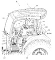
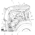
作業車両としてのトラクタA1は、図1~図4に示すように、前後方向に伸延した一定幅の長手鋼板を縦幅方向に立て左右に配設構成した機体フレーム1を中心とし、その前部に原動機部2を搭載している。原動機部2の後方には運転部3が配設されている。機体フレーム1の下方にはエンジンEからミッションケースMを介して動力が伝達される前後車輪FT,RTが軸架されている。
ミッションケースMは機体フレーム1に一体的に固設されている。ミッションケースMの後端にはPTO軸(図示せず)が突出している。PTO軸は、例えばロータリ耕耘機等の対地作業機にPTO駆動力を伝達するための軸である。ミッションケースMは、トラクタA1の後部に連結具、リフター等(図示せず)を介して連結される各種作業機へ動力を伝達可能に構成されている。ミッションケースMの内部には、油圧無段変速機、前後進切換機構、副変速ギヤ機構、二駆四駆切換機構、後輪用差動ギヤ機構などが設けられている。
トラクタA1は、キャビンCにより運転部3を被覆しているキャビンタイプのトラクタとして構成されている。
まず、トラクタA1の全体構成について説明し、続いて、本発明の特徴となる運転部3の構成について説明する。
[全体構成]
トラクタA1は、図1~図4に示すように、前後方向に延伸させて枠組形成した機体フレーム1の前部に原動機部2を設けるとともに、機体フレーム1の後端部にミッションケースMを設けている。原動機部2とミッションケースMは、動力伝動シャフト(図示せず)を介して互いに連動連結されている。
トラクタA1は、図1~図4に示すように、前後方向に延伸させて枠組形成した機体フレーム1の前部に原動機部2を設けるとともに、機体フレーム1の後端部にミッションケースMを設けている。原動機部2とミッションケースMは、動力伝動シャフト(図示せず)を介して互いに連動連結されている。
そして、機体フレーム1の前部には、左右方向に軸線を形成したフロントアクスルケースFAが取り付けられている。フロントアクスルケースFAの左右側端部に前車輪軸(図示せず)を介して前車輪FT,FTが取り付けられている。
また、ミッションケースMの左右側部には、それぞれリヤアクスルケースRA,RAが取り付けられ、各リヤアクスルケースRA,RAに後車輪軸4を介して後車輪RT,RTが連動連結されている。ミッションケースMとフロントアクスルケースFAは、前輪駆動シャフト(図示せず)を介して連動連結して、前・後車輪FT,RTを駆動する四輪駆動を可能としている。
トラクタA1は、機体フレーム1上において、原動機部2の後方に運転部3を配設している。具体的には、トラクタA1は、機体フレーム1の側方にそれぞれ取り付けた左右ベースフレーム5上に運転部3を載置固定している。また左右ベースフレーム5は後部側を上方に折曲した傾斜フレーム6を有する。左右ベースフレーム5の後端部にはリヤアクスルケースRAに関連して設けられた水平連結板7を介して補助ビーム8が一体に略垂直に立設されている。
また、左右ベースフレーム5は、その前端を機体フレーム1の側方に突設した運転部載置片11上に防振音プレート12を介して載置固定させている。左右ベースフレーム5は、その後端については、左右のリヤアクスルケースRA,RA上に防振音プレート12を備えた緩衝装置218を介して補助ビーム8の下端部を載置固定させている。
運転部3は、原動機部2の直後方位置からミッションケースMの直前方位置まで左右ベースフレーム5上に床面部としての運転部フロア9を張設している。具体的には、左右ベースフレーム5間に平面視門型のフロア載置板220と平面視矩形状のフロア補強板221が連設され、これらの上に各1枚ずつで構成した左右ステップSL,SRが載置固定されると共に上方に運転部フロア9が重畳的に張設されている。
左右ベースフレーム5の傾斜フレーム6上には、運転席13を構成するための運転席フレーム14が載置して連結されている。すなわち、運転席フレーム14は、水平の座席フレーム15と、その後縁部に傾斜して立ち上げた背フレーム16と、座席フレーム15の前端下方に垂設した前フレーム17と、前フレーム17の下端から前方に延出した防塵板18と、で構成されている。防塵板18は、運転部フロア9の後端縁部との連結により、運転席フレーム14の前端下方を閉塞して地面から運転席13下方空間を通して舞い上がる塵芥が運転部3に浸入することを防止している。
また、背フレーム16の外側面には傾斜フレーム6の外側面に当接して立ち上げ連設した略三角形状の当て板19が密着当接してボルトにより固定されている。更には、かかる座席フレーム15と左右ベースフレーム5の傾斜フレーム6から立ち上げた当て板19との間には後車輪RTの内側をカバーするフェンダ20のフェンダ内壁部21が挿入されて座席フレーム15と当て板19との間で挟持されると共に、これらの三個の部材はボルトにより一体に強固に連結されている。
すなわち、原動機部2のエンジンE後方に位置するミッションケースM上方に、運転席13が配設され、運転席13の左右側方に左右一対のフェンダ20L,20Rが配設されている。左右一対のフェンダ20L,20Rは、運転部フロア9の後部左右側方から立ち上げて形成され、後車輪RT,RTの前上部を被覆する。なお、一対のフェンダ20L,20Rには、フェンダ20L,20Rの外側縁部を被覆すると共に更に外方に延出したアウターフェンダ42L,42Rが張設されている。
図5に示すように、機体フレーム1の前部には、作業機としてのフロントローダ50が着脱可能に取り付けられる。フロントローダ50は、機体フレーム1に着脱可能に設けられる左右一対のマスト51と、マスト51に上下回動可能に連結される左右一対のリフトアーム52と、左右一対のリフトアーム52を連結する連結パイプ53と、左右一対の作業具リンク54と、左右一対の作業具ブラケット55と、左右一対のリフトアーム52に装着される作業具56と、左右一対のアームシリンダ57と、左右一対の作業具シリンダ58と、スタンド59と、トラクタA1の前部を保護するフロントガードとを備える。フロントローダ50は、作業具56を昇降させて作業を行う。本実施形態では、作業具56としてバケットが用いられているが、他の作業具を取り付けることも可能である。
機体フレーム1を構成する左右の板状部材の外側に、左右一対のローダマウント60がそれぞれ固定される。左右一対のローダマウント60には、左右一対のマスト51が着脱可能に取り付けられる。リフトアーム52は、マスト51に取り付けられる後リフトアーム52aと、作業具56に取り付けられる前リフトアーム52bとにより、機体側面視でブーメラン状の形態をなすように構成されている。後リフトアーム52aと前リフトアーム52bとは、所定の角度をなすように溶接により互いに固定されている。
左右のリフトアーム52の後端は、それぞれマスト51の上端部の枢支軸61にて枢支されている。これにより、フロントローダ50は、左右一対の枢支軸61を中心として、前部が上下回動可能に構成されている。マスト51の上下中途部の前端部には、アームシリンダ57のピストンロッドの先端部(後端)が枢支されており、後リフトアーム52aの前端部の下方側のアームシリンダブラケット部には、アームシリンダ57の基端部(前端)が枢支されている。そして、左右一対のアームシリンダ57が、フロントローダ50の上下回動のためのアクチュエータとなっており、左右のアームシリンダ57のピストンロッドの同時伸縮により、フロントローダ50の上下回動角度、すなわち、左右一対のリフトアーム52のマスト51に対する角度が調整される。
左右の前リフトアーム52bは、その前後中途部同士が機体幅方向を長手方向とする連結パイプ53によって互いに連結されることで、一体的に固定されている。前リフトアーム52bの前端は、作業具ブラケット55を介して作業具56に取り付けられている。作業具ブラケット55には、前リフトアーム52bの前端が枢支されている。これにより、作業具ブラケット55及び作業具56は、左右一対のリフトアーム52に対して上下回動可能となっている。
各作業具リンク54は、アーム側リンク部材54aと、作業具側リンク部材54bとから構成されている。アーム側リンク部材54aの下端は、前リフトアーム52bの前後中途部に枢支されている。作業具側リンク部材54bの下端は、作業具ブラケット55の上部に枢支されている。
リフトアーム52の前端部の上方側には、作業具シリンダ58が取り付けられている。アーム側リンク部材54a及び作業具側リンク部材54bの上端部は、作業具シリンダ58のピストンロッドの先端部を枢支している。作業具シリンダ58の基端部は、後リフトアーム52aの前端部の上方側に枢支されている。左右一対の作業具シリンダ58が、作業具ブラケット55の前後回動のためのアクチュエータとなっており、左右の作業具シリンダ58のピストンロッドの同時伸縮により、作業具リンク54の折れ角、すなわち、アーム側リンク部材54aと作業具側リンク部材54bとがなす角度が調整され、作業具ブラケット55のリフトアーム52に対する前後回動角度が調整され、作業具56の回動角度が調整される。
運転部3の右側方に位置するフェンダ20R上、及びその近傍には、図10、図11に示すように、フロントローダ50の昇降作業を行うためのローダ操作部29、油圧外部取出バルブ(図示略)を切換操作するための油圧操作部30、他の操作レバー330,332及びスイッチ類331が配設されている。
運転部フロア9の前端縁部には、図3、図8、図9等に示すように、原動機部2と運転部3とを遮蔽する熱風遮蔽板200が立設されている。熱風遮蔽板200の運転部3側には、連結ケース27が突設され、更に連結ケース27に固設されたステアリングブラケット28に傾斜自在に装着されたステアリングコラム24にハンドル支軸26介してハンドルHが設けられている。
ステアリングコラム24の前上方には、熱風遮蔽板200の上端縁にダッシュボード25が取り付けられると共に、ステアリング機構22はハンドルH以外をステアリングカバー43により被覆している。ステアリングカバー43の右側には、エンジンEの回転速度を設定保持するためのアクセルレバー65が設けられている。
また、各種操作ペダル23は熱風遮蔽板200に突設した連結ケース27に支持され、左からクラッチペダルCP、左ブレーキペダルLBP、右ブレーキペダルRBPを配設している。また、床面を構成する右ステップSR上には、アクセルペダルAPが突設されている。アクセルペダルAPは、エンジンEの回転速度または車速などを制御するアクセル連動の主変速ペダルとして機能する。アクセルペダルAPの上下動を検出するポテンショメータ(可変抵抗器)型のペダルセンサが、右ステップSRの下側で固定されている。なお、床面は略全体的に平坦面である
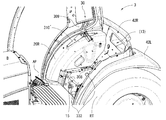
運転席フレーム14に形成された水平の座席フレーム15上には、図10、図11に示すように、左右アームレスト300L,300Rを備えた運転席13が載設されている。運転席13の左右側、特に右側のフェンダ20R上及びその近傍には、上述の通りローダ操作部29や油圧操作部30や他の各種操作レバー330,332や種々のモード切替等のスイッチ類331が集中的に配設され、運転者による操作が容易とされている。
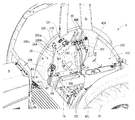
キャビンCは、図1、図4~図7に示すように、六面体を形成するように枠組み形成されたキャビンフレーム222と、キャビンフレーム222を形成する各片により形成された各面部223,225,231,236とから形成されている。
すなわち、キャビンフレーム222は、天井面部223に扁平箱状に形成した天井部224を張設し、前面部225の上部にフロントガラス部226を張設するとともに、下部に左右側前壁部227を張設している。また、キャビンCの下部の中央部においては、熱風遮蔽板200がキャビンCの前面部225の一部を構成している。すなわち、熱風遮蔽板200と熱風遮蔽板200の左右に張設した左右側前壁部227と熱風遮蔽板200の上部に張設したフロントガラス部226とで前面部225が構成されている。
後面部231は、図3、図4、図7に示すように、補助ビーム8の上端を連結ブラケット233を介してフェンダ20の後端及びキャビンフレーム222の後下端と一体に連設している。また、キャビンフレーム222の後面中段に設けた後方横フレーム232は、運転席フレーム14の背フレーム16にボルトにより一体に連結されている。
しかも、キャビンフレーム222の前部下端縁部、すなわち、フェンダ20上に載置される半円弧フレーム234前方の水平下部フレーム235は図13、図14に示すように、ステップSの外縁部に当接して一体に連設されている。
左右側面部236の前部には、左右一対の乗降扉部237,237が開閉自在に張設されている。図11に示すように、乗降扉部237の外部には、開閉操作グリップ239が設けられている。乗降扉部237の内面には、グリップパイプ238が張設されている。
左右側面部236の後部には、左右一対のサイド窓部240が開閉自在に張設されている。後面部231には、リヤガラス部241が開閉自在に張設されている。
原動機部2は、図2に示すように、機体フレーム1の前部にエンジンE等を配設して構成されている。エンジンEの直前方には、冷却ファン31、ラジエータ32が立設されている。
上記のように構成した原動機部2には、ボンネット支持枠体(図示せず)を設けて、ボンネット支持枠体にボンネットBを開閉自在に取り付け、ボンネットBにより原動機部2のエンジンルームを被覆・開放自在としている。
ボンネットBは、船底を逆さにしたような形(いわゆる、船底天井)に形成した天井面部33と、網目状のフロントグリル34と、左右側面部35,35と、から下方と後方が開口する箱型に形成されている。
上記のように構成した原動機部2を被覆するボンネットBと運転部3との間に形成された間隙36には、図8、図10に示すように、排熱孔38を有する排熱カバー37が介設されている。また、排熱カバー37は、熱風遮蔽板200の上部と連設している。
本発明の実施形態に係るトラクタA1は以上のような基本構造を備える。
次に、本発明の要部となる運転部3におけるフェンダ20R周縁の具体的な構成について説明する。
[運転部]
本実施形態に係るトラクタA1の運転部3は、次のような構成を備える。すなわち、ハンドルHの後方に運転席13を配置し運転席13の近傍にローダ操作部29と油圧操作部30とを配置したトラクタの運転部3において、図10に示すように運転席13の右側のアームレスト300R上に肘付きした運転者の右肘を中心に右腕の半円弧回動の範囲内にローダ操作部29と油圧操作部30を配置したことを特徴とする。ローダ操作部29及び油圧操作部30は、運転席13に座った状態の運転者が右肘をアームレスト300R上の所定の位置に付けた状態で、つまりアームレスト300R上に付けた右肘を移動させることなく、右手で操作可能な範囲内に設けられている。
本実施形態に係るトラクタA1の運転部3は、次のような構成を備える。すなわち、ハンドルHの後方に運転席13を配置し運転席13の近傍にローダ操作部29と油圧操作部30とを配置したトラクタの運転部3において、図10に示すように運転席13の右側のアームレスト300R上に肘付きした運転者の右肘を中心に右腕の半円弧回動の範囲内にローダ操作部29と油圧操作部30を配置したことを特徴とする。ローダ操作部29及び油圧操作部30は、運転席13に座った状態の運転者が右肘をアームレスト300R上の所定の位置に付けた状態で、つまりアームレスト300R上に付けた右肘を移動させることなく、右手で操作可能な範囲内に設けられている。
また、油圧操作部30のブラケットである油圧操作ブラケット310は、図12に示すように運転部3を収納するキャビンC内に突設されたフェンダ20のフェンダ外周面302に固設されている。そして、フェンダ20のフェンダ外周面302と油圧操作ブラケット310及びローダ操作部29ブラケットであるローダ操作ブラケット307を、各操作部29,30を支持するガイド体303で一括して被覆するように構成したことにも特徴を有する。
運転部3は、図8~図12に示すように、運転席13の前方にハンドルHを有し、ハンドルHの前方にはダッシュボード25内に設置された表示装置(図示せず)を備える。表示装置には、各種計器類が配設されている。ハンドルH下方の床面上方には各種操作ペダル23が配置されている。
また、運転席13の左右側方には、キャビンC内の運転部3に突設された図13に示すような半円弧状のフェンダ20L,20Rが配設されている。右側のフェンダ20R上、すなわちフェンダ外周面302、及びその近傍には、作業機の昇降作業を行うためのローダ操作部29、及び油圧に関する操作を行うための油圧操作部30や、他の操作レバー330,332やスイッチ類331が配設されている。また、ローダ操作部29及び油圧操作部30は、右アームレスト300R周りに平面視で半円弧軌跡T上に位置するように配設されている(図10参照)。
また、ローダ操作部29及び油圧操作部30は、それぞれの先端部の高さ位置が右アームレスト300Rの上面から若干だけ上方の位置であって互いに略同じ高さ位置となるように配設されている。ローダ操作部29は、アクセルペダルAPの後方に設けられている。また、油圧操作部30は、ローダ操作部29の後方に設けられている。
具体的には、ローダ操作部29は、棒状のローダ操作レバー体304と、該ローダ操作レバー体304の先端にモード切替等が可能な各種操作スイッチ(305a,305b,305c)を備えた把持部306とを有し、一体のローダレバーとして構成されている。図10、図14に示すように、運転席13の前端右側とフェンダ20Rとの間、すなわち、運転席13とフェンダ20Rとの間に位置する座席フレーム15上に、ローダ操作ブラケット307が固設されている。ローダ操作ブラケット307は、矩形板状で略L字状の部材を主として構成されている。ローダ操作部29は、その基部をローダ操作ブラケット307に連結させ、揺動操作自在に立設されている。なお、ローダ操作部29は右側のフェンダ20Rの外周面に位置するように配設してもよい。
ローダ操作部29は、フロントローダ50の油圧機器に作動油を供給制御するためのローダバルブ(図示略)を切り替え操作するためのレバー操作部である。なお、ローダバルブは、機体フレーム1の側面部等にブラケット等を介して設けられている。ローダ操作部29のローダ操作レバー体304が、ローダ操作ブラケット307に揺動可能に支持されている。ローダ操作部29は、ローダ操作ブラケット307にリンク部材等を介して連結固定されたプッシュプルワイヤー63,64を介して、ローダバルブと連結されている。
一方のプッシュプルワイヤー63の先端は、左右傾動用のリンク部材に連結されている。左右傾動用のリンク部材は、ローダ操作部29の左右傾動動作に合わせて左右方向に揺動可能にローダ操作ブラケット307に支持されている。ローダ操作部29が左右傾動動作することにより、左右傾動用のリンク部材を介して、プッシュプルワイヤー63の先端が上下動する。
他方のプッシュプルワイヤー64の先端は、前後傾動用のリンク部材に連結されている。前後傾動用のリンク部材は、ローダ操作部29の前後傾動動作に合わせて前後方向に揺動可能にローダ操作ブラケット307に支持されている。ローダ操作部29が前後傾動動作することにより、前後傾動用のリンク部材を介して、プッシュプルワイヤー64の先端が上下動する。
ローダ操作部29の前後傾動操作に対応してプッシュプルワイヤー64が押し引きすることにより、上述したローダバルブにおけるアームバルブが作用する。これにより、アームシリンダ57が伸縮駆動して左右リフトアーム52が昇降回動し、作業具56が昇降動する。また、ローダ操作部29の左右傾動操作に対応してプッシュプルワイヤー63が押し引きすることにより、ローダバルブにおける作業具バルブが作用する。これにより、作業具シリンダ58が伸縮駆動して作業具56が回動する。作業具56の上向きの回動により、土等を掬うチルト動作が行われ、作業具56の下向きの回動により、土等を落とすダンプ動作が行われる。
また、ローダ操作ブラケット307の後方には、座席フレーム15に前後方向を長手方向として穿設された長孔308の下方から挿貫され上方に突出する操作レバー330が配設されている。操作レバー330は、比較的操作頻度が高い別途の操作部である。操作レバー330の先端の高さは図11、図12に示すように右アームレスト300Rよりも低い位置となっている。操作レバー330は、例えばロータリ耕耘機などの対地作業機の高さ位置を変更調節する作業部ポジションレバーである。
また、運転席13の右側方でフェンダ20Rの後端上部近傍には、油圧操作部30が配設されている。油圧操作部30には、油圧外部取出バルブを切換操作するための3本の油圧操作レバー(SCVレバー)309が配設されている。各油圧操作レバー309は、棒状で先端に把持部を有する。3本の油圧操作レバー309は、前後に隣接して配設されている。ここで、油圧外部取出バルブは、トラクタA1に後付けされるロータリ耕耘機やコンポキャスタ等の作業機の油圧機器に作動油を供給制御するためのものである。油圧操作レバー309は、油圧外部取出バルブの数に合わせた本数配置される。つまり、本実施形態では、3連の油圧外部取出バルブが設けられている。
各油圧操作レバー309の基部は、図14に示すように、油圧操作ブラケット310に連結されている。油圧操作ブラケット310は、右側のフェンダ20Rのフェンダ外周面302にフェンダ20Rに沿って屈曲して固設された矩形板状の部材を主として構成されている。油圧操作部30に配設された各油圧操作レバー309は、その基部を油圧操作ブラケット310に連結させ、操作自在に立設されている。
なお、油圧操作ブラケット310の前部上方には、後述するガイド体303に連設されたモード切替スイッチ等のスイッチ類331が配設される。具体的には、スイッチ類331として、PTOクラッチスイッチ331aと、回転数/車速設定ダイヤル331bと、回転数/車速選択スイッチ331cと、車速感度調節ダイヤル331dとが配設されている(図12参照)。PTOクラッチスイッチ331aは、PTO軸からロータリ耕耘機等の作業機への動力伝達を継断操作するための操作部である。回転数/車速設定ダイヤル331bは、エンジンEの最高回転速度又は機体フレーム1の最高走行速度を予め設定するための操作部である。回転数/車速選択スイッチ331cは、回転数/車速設定ダイヤル331bで設定する値をエンジンEの最高回転速度又は機体フレーム1の最高走行速度のいずれであるか指定するための操作部である。車速感度調節ダイヤル331dは、アクセルペダルAPの操作時などにおける車速の加減速度を調整するための操作部である。
また、ローダ操作部29において、把持部306の前面には、エンジンあおりスイッチ305aが設けられており、把持部306の左側面には、バルブ操作スイッチ305bとモード切換スイッチ305cが設けられている。オペレータの右手で把持部306が把持されるため、人差し指などで操作可能な位置にエンジンあおりスイッチ305aが配置されるとともに、親指で操作可能な位置にバルブ操作スイッチ305b及びモード切換スイッチ305cが配置されている。そのため、オペレータは、フロントローダ50によるローダ作業時において、ローダ操作部29を把持した状態で、各スイッチ305a、305b及び305cを容易に操作できる。
エンジンあおりスイッチ305aは、例えば、フロントローダ50により土等を掬うチルト動作や地面を掻くドーザ動作などの実行中に高負荷がかかる場合などに使用される。エンジンあおりスイッチ305aを操作することで、エンジンEのエンジン回転数を上昇させる一方、油圧無段変速機による変速比を下げて、トラクタA1の車速を一定に保つエンジンあおり制御を実行する。エンジンあおり制御は、副変速レバーにより3速まで指定できる副変速のうち、1速及び2速が指定されている場合であって、モード切換スイッチ305cによるモード切換制御が実行されていないときに、エンジンあおりスイッチ305aの押下中に実行される。
ローダ操作部29にエンジンあおりスイッチ305aを配置することで、オペレータは、フロントローダ50によるローダ作業中の聴覚及び視覚に基づき、高負荷作業であると判断すると同時に、ローダ操作部29を操作している手(本実施形態では右手)で簡単にエンジンあおり制御を実行させる。これにより、作業負荷に満たない場合であっても、オペレータの判断に従い瞬時に対応し、アームシリンダ57及び作業具シリンダ58に対する油圧揚力を上昇できるため、フロントローダ50などの作業機操作における煩雑さを解消させるだけでなく、作業機にかかる負担を低減できる。
バルブ操作スイッチ305bは、例えば、フロントローダ50の作業具56として、牧草ロールなどを狭持するベールグラブ(図示略)が使用される場合など、アームシリンダ57及び作業具シリンダ58以外の油圧シリンダが作業具56に設けられている構成において使用される。バルブ操作スイッチ305bを操作することで、作業具56となるベールグラブにおけるベールグラブ用シリンダが伸縮し、牧草ロールの狭持又は開放を実行できる。
すなわち、ローダ操作部29の前後傾動操作により、アームシリンダ57を作用させて、作業具56を上下に昇降させるとともに、ローダ操作部29の左右傾動操作により、作業具シリンダ58を作用させて、作業具56となるベールグラブを上下に傾動させ、更に、ローダ操作部29のバルブ操作スイッチ305bを操作することにより、ベールグラブ用シリンダを作用させて、作業具56となるベールグラブの開閉動作を実行させる。これにより、例えば、ベールグラブを作業具56として使用した場合、ローダ操作部29のみで、牧草ロールの荷台への積み込み作業などを実行でき、オペレータの操作性が向上する。
モード切換スイッチ305cは、予め複数のモードに対して設定された最高回転速度及び最高速度を切り換える場合に使用される。本実施形態では、第1モード及び第2モードの2モードの場合として説明するが、3モード以上の設定が実行できるものとしてもよい。第1及び第2モードにおける最高回転速度及び最高車速は、回転数/車速設定操作具となる回転数/車速設定ダイヤル331b及び回転数/車速選択スイッチ331cが操作されることで設定される。なお、第1及び第2モードそれぞれで設定される最高回転速度及び最高車速として、アクセルレバー65やアクセルペダルAPの最大位置でのエンジンEの回転速度及びトラクタA1の車速が設定される。
モード切換スイッチ305cを操作することで、第1モード及び第2モードの切換が実行され、モード切換スイッチ305cへの操作に応じて、第1及び第2モードによる最高回転速度及び最高車速が切り換えられる。本実施形態では、第1モードにおける最高回転速度及び最高車速に対して、第2モードにおける最高回転速度及び最高車速が小さい値となるように設定される。
このとき、例えば、フロントローダ50による運搬作業を行っている場合、作業具56で運搬対象物(土、雪、牧草ロールなど)を保持しているとき、モード切換スイッチ305cを操作して第2モードに切り換えることで、トラクタA1を低速で移動させるため、運搬対象物の落下などを防止できる。一方、作業具56に運搬対象物がない場合は、モード切換スイッチ305cを操作して第1モードに切り換えることで、トラクタA1を高速で移動させるため、搬出先から搬入元までの移動時間を短縮でき、作業の効率化を図れる。
ローダ操作部29にモード切換スイッチ305cを配置することで、オペレータは、フロントローダ50による運搬作業中において、運搬対象物の有無に基づいて、ローダ操作部29を操作している手(本実施形態では右手)で簡単にトラクタA1の移動速度を切り換える。従って、フロントローダ50における運搬対象物の運搬時には、運搬対象物の落下を防止しつつ、運搬対象物の運搬終了後の移動時には、移動時間を短縮できるため、作業の効率化を図れる。
また、本実施形態に係るトラクタA1において、アクセルペダルAPに関する動作制御として、アクセル連動制御が行われる。アクセル連動制御が実行されている場合、各モードに対して設定される最高車速として、アクセルペダルAPのみを最大位置としたときの車速が設定される。一方、アクセル連動制御が実行されていない場合は、各モードに対して設定される最高車速として、アクセルペダルAP及びアクセルレバー65のそれぞれを最大位置としたときの車速が設定される。
なお、アクセル連動制御が実行されるとき、アクセルペダルAPの踏み込み量に応じて、トラクタA1の車速が変更するとともに、アクセルレバー65により設定された最低回転数からエンジンEの回転数が変更する。例えば、アクセルペダルAPの踏み込み量が多くなるにともない、エンジンEの回転数が増加するとともに、トラクタA1の車速が増加する。一方、アクセル連動制御が実行されていない場合は、アクセルペダルAPの踏み込み量に応じて、エンジンEの回転数をアクセルレバー65により設定された最低回転数で一定に維持した状態で、トラクタA1の車速が変更する。例えば、アクセルペダルAPの踏み込み量が多くなるにともない、エンジンEの回転数はアクセルレバー65により設定された最低回転数で保持されながら、トラクタA1の車速が増加する。なお、アクセル連動制御を実行させるためのスイッチは、例えばステアリングコラム24の上面に配置される。
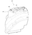
以上のように配設されたローダ操作部29や油圧操作部30等の各種操作部は、図12に示すように各ブラケット307,310と、運転部3に露出するフェンダ20Rとを図15に示すガイド体303により一括して被覆されている。なお、ガイド体303には、ガイド体303に隣接する周縁部材と異なる色彩が付されている。これにより、ローダ操作部29や油圧操作部30等の各種操作部が配設された領域がハンドルH操作とは異なる操作を行う領域であることが視覚的に認識しやすくされている。
なお、図10、図12に示すように、運転席13の左側方に位置する座席フレーム15上には、図4に示すように座席フレーム15に前後方向を長手方向として穿設された長孔315の下方から挿貫され上方に突出する操作レバー332を配設している。操作レバー332は、操作頻度の少ない別途の操作部である。操作レバー332としては、例えば、ミッションケースM内に設けられた走行副変速ギヤ機構の出力範囲を切換える副変速レバーと、前・後車輪FT,RTの二駆と四駆とを切り換える四駆レバーとが配設される。
ガイド体303は、図15に示すように、下方側を開放側とした凹状の略湾曲形状に形成されており、フェンダ20Rのフェンダ外周面302となる上部の一部と側部の大半を上方から被覆可能な部材である。ガイド体303の前端側には、ローダ操作部29のローダ操作レバー体304を挿貫するローダ操作レバー挿貫孔318が貫通して形成されている。すなわち、ガイド体303において、ローダ操作レバー挿貫孔318が形成された部分は、運転部フロア9の床面から上方に外観視筒状に立設された部分であり、上下端側に開口を形成している。
また、ガイド体303の上部側の中途部には、各種スイッチ類331等を操作自在に取り付けて機構部分を被覆する矩形箱状のスイッチ類取付部319が立設されている。スイッチ類取付部319には、スイッチ類331の各操作部が表面から露出するようにスイッチ類取付孔320が複数穿設されている。
また、ガイド体303の上部後端側には、油圧操作部30の油圧操作レバー309を挿貫する油圧操作レバー挿貫長孔321が形成されている。油圧操作レバー挿貫長孔321は、その長手方向が平面視で前後方向に対して略45°の傾斜角度をなし車両左右方向の内側から外側にかけて斜め前方となるように形成されている。3つの油圧操作レバー挿貫長孔321は、前後に隣接して互いに平行に形成されている。
更に、ガイド体303の側部の中途部には、操作レバー330を挿貫するレバー挿貫長孔322が形成されている。レバー挿貫長孔322は、平面視で前後方向を長手方向とするガイド孔である。レバー挿貫長孔322は、上述したローダ操作レバー挿貫孔318やスイッチ類取付孔320や油圧操作レバー挿貫長孔321よりも低い位置に形成されている。
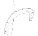
本実施形態のガイド体303は以上のように形成されているが、ガイド体303で被覆されないフェンダ20Rの露出部分は、別途のフェンダカバー(図示せず)で被覆しても良い。
ここで、ローダ操作部29と油圧操作部30のレイアウトについて、右アームレスト300Rを基準に詳述する。ローダ操作部29は、平面視で右アームレスト300Rの前方において若干だけ右側に位置する。また、油圧操作部30は、平面視で右アームレスト300Rの右側方において右アームレスト300Rの中途部から後端部にかけて外側に湾曲して位置する。
そして、ローダ操作部29と油圧操作部30を結ぶ平面視の軌跡は、図10に示すように半円弧軌跡T上に位置している。具体的には、平面視における弧状の軌跡(T)は、ローダ操作部29としてのローダレバーの操作移動範囲、及び油圧操作部30の各油圧操作レバー309の操作移動範囲を通過する。このように、ローダ操作部29及び油圧操作部30は、それぞれの操作部(レバー)の操作移動範囲におけるいずれかの操作位置を、平面視における弧状の軌跡(T)上に位置させるように配置されている。
また、図10に示すように、右アームレスト300Rの略前方(矢印D1参照)にローダ操作部29が設けられ、右方向に略直角をなす方向(矢印D2参照)の位置に油圧操作部30が設けられている。右アームレスト300Rの右斜め45°の領域にはローダ操作部29等と略同高さの操作レバーは配設されておらず、該領域には、高さの異なる別途の操作レバー330と各種のスイッチ類331が配設されている。
このように、ローダ操作部29及び油圧操作部30が位置しない右アームレスト300Rの右斜め45°の領域に配設された比較的操作頻度の高い別途の操作レバー330は、先端部の高さが各操作部29,30よりも明らかに低いことも含めて、各操作部29,30とは配置的に明確に分離されている。
また、本実施形態に係るトラクタA1は、エンジンEの回転速度または車速を制御するアクセル連動のアクセルペダルAPを備え、ローダ操作部29は、アクセルペダルAPの後方に設けられている。このような構成によれば、主変速用の操作部材として例えば主変速レバー等の手動操作される操作部材を設けることなく、アクセルペダルAPのペダル操作によりエンジンEの回転速度または車速を制御することが可能となる。これにより、手動操作による操作対象を削減することができ、ローダ操作部29の操作時における作業性を向上することができるとともに、ローダ操作部29を操作する際の運転者による作業負担を軽減することができる。
[変形例]
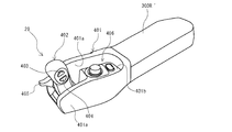
また、ローダ操作部29は、図16~図22に示す変形例のように右アームレスト300R´の先端部に配置することもできる。
また、ローダ操作部29は、図16~図22に示す変形例のように右アームレスト300R´の先端部に配置することもできる。
図18に示すように、この変形例のローダ操作部29は、右アームレスト300R´の先端側において右アームレスト300R´と一体的に前方に延設されたレバー支持部401の先端部に前後傾動可能に支持されたローダ操作レバー体402を有する。レバー支持部401は、左右方向に互いに対向する支持側壁部401aを有する。左右の支持側壁部401a間に、左右方向を回動軸方向として、ローダ操作レバー体402が支承されている。ローダ操作レバー体402は、レバー支持部401の前端部から上方(詳細には斜め前上方)に向けて延出している。ローダ操作部29は、上述したように2本のプッシュプルワイヤーを介してローダバルブと連結されている。
また、ローダ操作レバー体402の左側面には、フロントローダ50の作業具56を回動操作するための回動操作スイッチ403,404がローダ操作レバー体402の長手方向に沿って2箇所に設けられている。回動操作スイッチ403,404は、押圧操作されるボタン式のスイッチである。上側の回動操作スイッチ403を押圧操作することで、作業具56が一方(上方)に回動し、下側の回動操作スイッチ404を押圧操作することで、作業具56が他方(下方)に回動する。
ローダ操作レバー体402の前後傾動操作に対応して2本のプッシュプルワイヤーのうちの一方のプッシュプルワイヤーが押し引きすることにより、ローダバルブにおけるアームバルブが作用する。これにより、フロントローダ50においてアームシリンダ57が伸縮駆動して左右リフトアーム52が昇降回動し、作業具56が昇降動する。
また、ローダ操作レバー体402側面の回動操作スイッチ403,404のいずれかのスイッチの押圧操作に対応して2本のプッシュプルワイヤーのうちの他方のプッシュプルワイヤーが押し引きすることにより、ローダバルブにおける作業具バルブが作用する。これにより、フロントローダ50において作業具シリンダ58が伸縮駆動して作業具56が回動する。
なお、ローダ操作レバー体402の前側には、フロントローダ50の作業具56の昇降動作に関し、作業具56の昇降の微調整を行うための昇降レバー405が突設されている。昇降レバー405は、ローダ操作レバー体402に対して上下動するツマミ型のレバーである。昇降レバー405を上側に移動操作することで、アームシリンダ57の動作により作業具56が微量ずつ上昇し、昇降レバー405を下側に移動操作することで、アームシリンダ57の動作により作業具56が微量ずつ下降する。
また、レバー支持部401におけるローダ操作レバー体402の後方には、スイッチ配置面部401bが設けられており、スイッチ配置面部401bに、スイッチ類406が配設されている。スイッチ類406としては、例えば、上述した回転数/車速設定ダイヤルや回転数/車速選択スイッチ等が配置される。
本変形例においても、上述した平面視でのレイアウトについて、ローダ操作部29は右アームレスト300R´の略前方(矢印D1参照)となり、油圧操作部30は同様にアームレスト300R´の右方向に略直角をなす方向(矢印D2参照)の位置に配設される。また、本変形例では、油圧操作部30の油圧操作レバー309を2本で構成しているが、油圧操作レバー309の本数は、上述のとおり油圧外部取出バルブの数に合わせた数であり、本実施形態に限定されるものではない。
なお、図19はフェンダ20R上に本変形例に係る油圧操作ブラケット310´を介して油圧操作レバー309を操作自在に立設した状態を示し、図20は本変形例に係るガイド体303´を示し、図21はガイド体303´で被覆されないフェンダ20Rの露出部分を被覆するためのカバー体334を示し、図22はカバー体334でフェンダ20Rの一部を被覆した状態を示している。
以上説明したように構成された本実施形態に係るトラクタA1は、ハンドルHの後方に運転席13を配置し運転席13の近傍にローダ操作部29と油圧操作部30とを配置した運転部3を備えた構成において、運転席13の右側のアームレスト300R上に肘付きした運転者の右肘を中心に右腕の半円弧回動の範囲内にローダ操作部29と油圧操作部30を配置した構成を備える。このような構成により、ローダ操作部29や油圧操作部30と、ハンドルHの夫々の把持を異なる側の手で確実に行うことができ、トラクタA1の運転と牽引等する作業機の操作等を明確に分けて並行して行うことができる。このため、作業性の向上を図ることができるばかりでなく、アームレスト300R上に右肘を載置した状態でローダ操作部29等を操作することができるため作業時の疲労を大幅に緩和することができる。
更に、右腕の半円弧回動の範囲内にはローダ操作部29や油圧操作部30以外の操作部も配置することができるため、更なる作業性の向上を図ることができる。
また、油圧操作部30のブラケットである油圧操作ブラケット310は運転部3を収納するキャビンC内に突設されたフェンダ20のフェンダ外周面302に固設されている。そして、トラクタA1は、フェンダ20Rのフェンダ外周面302と各操作部29,30の各ブラケット307,310とを各操作部29,30を支持するガイド体303で一括して被覆するように構成されている。このような構成により、各操作部29,30が集中配置された状況を視覚的に統一感のある外観として現出でき、ハンドルHの操縦によるトラクタA1の運転と、各操作部29,30による牽引等する作業機の操作等とを視覚的にも明確に分けることができるため作業性の向上を図ることができる。
更に、ローダ操作部29及び油圧操作部30それぞれブラケット307,310を夫々別個の部材で被覆することなくガイド体303で一括して被覆できるので、組立作業性を向上させることができると共に、製造コストを低廉に抑えることができる。
以上、本発明の好ましい実施の形態について説明したが、本発明は上述した特定の実施形態に限定されるものではなく、特許請求の範囲に記載された本発明の要旨の範囲内において、種々の変形・変更が可能である。
上述した実施形態においては、ローダ操作部29及び油圧操作部30それぞれに対応するローダ操作ブラケット307及び油圧操作ブラケット310が設けられており、油圧操作ブラケット310がフェンダ外周面302に固設され、両方のブラケット307,310とフェンダ外周面302がガイド体303により一括して被覆された構成が採用されている。この点、ガイド体303による被覆構成は、上記のような構成に限定されるものではなく、例えば変形例として示した構成のように、ローダ操作ブラケット307及び油圧操作ブラケット310のいずれか一方のブラケットが、フェンダ外周面302とともにガイド体303により一括して被覆された構成であってもよい。
A1 トラクタ
C キャビン
H ハンドル
3 運転席
20 フェンダ
29 ローダ操作部
30 油圧操作部
50 フロントローダ
300R 右側のアームレスト
302 フェンダ外周面
303 ガイド体
303´ 変形例のガイド体
307 ローダ操作ブラケット
309 油圧操作レバー
310 油圧操作ブラケット
C キャビン
H ハンドル
3 運転席
20 フェンダ
29 ローダ操作部
30 油圧操作部
50 フロントローダ
300R 右側のアームレスト
302 フェンダ外周面
303 ガイド体
303´ 変形例のガイド体
307 ローダ操作ブラケット
309 油圧操作レバー
310 油圧操作ブラケット
Claims (3)
- ハンドルの後方に配置された運転席の近傍にローダ操作部と油圧操作部とを配置した運転部を備えたトラクタにおいて、
前記ローダ操作部及び前記油圧操作部を、前記運転席の右側のアームレスト上に肘付きした運転者の右肘を中心に右腕の半円弧回動の範囲内に配置した
ことを特徴とするトラクタ。 - 前記油圧操作部のブラケットは、前記運転部を収納するキャビン内に突設されたフェンダのフェンダ外周面に固設されており、
前記フェンダ外周面と前記油圧操作部のブラケット及び前記ローダ操作部のブラケットの少なくともいずれか一方のブラケットとを、前記ローダ操作部及び前記油圧操作部を支持するガイド体で一括して被覆するように構成した
ことを特徴とする請求項1に記載のトラクタ。 - エンジンの回転速度または車速を制御するアクセル連動の主変速ペダルを備え、
前記ローダ操作部は、前記主変速ペダルの後方に設けられている
ことを特徴とする請求項1または請求項2に記載のトラクタ。
Priority Applications (3)
| Application Number | Priority Date | Filing Date | Title |
|---|---|---|---|
| EP16821063.1A EP3321153B1 (en) | 2015-07-07 | 2016-03-22 | Tractor |
| JP2016544174A JP6293289B2 (ja) | 2015-07-07 | 2016-03-22 | トラクタ |
| US15/741,997 US10940901B2 (en) | 2015-07-07 | 2016-03-22 | Tractor |
Applications Claiming Priority (2)
| Application Number | Priority Date | Filing Date | Title |
|---|---|---|---|
| JP2015-135986 | 2015-07-07 | ||
| JP2015135986 | 2015-07-07 |
Publications (1)
| Publication Number | Publication Date |
|---|---|
| WO2017006592A1 true WO2017006592A1 (ja) | 2017-01-12 |
Family
ID=57685376
Family Applications (1)
| Application Number | Title | Priority Date | Filing Date |
|---|---|---|---|
| PCT/JP2016/059064 Ceased WO2017006592A1 (ja) | 2015-07-07 | 2016-03-22 | トラクタ |
Country Status (4)
| Country | Link |
|---|---|
| US (1) | US10940901B2 (ja) |
| EP (1) | EP3321153B1 (ja) |
| JP (1) | JP6293289B2 (ja) |
| WO (1) | WO2017006592A1 (ja) |
Cited By (1)
| Publication number | Priority date | Publication date | Assignee | Title |
|---|---|---|---|---|
| JP2020001435A (ja) * | 2018-06-25 | 2020-01-09 | 株式会社クボタ | 作業車両 |
Families Citing this family (3)
| Publication number | Priority date | Publication date | Assignee | Title |
|---|---|---|---|---|
| JP6971773B2 (ja) * | 2017-10-20 | 2021-11-24 | 株式会社小松製作所 | 作業車両のキャブ、作業車両およびホイールローダ |
| WO2020003948A1 (ja) * | 2018-06-29 | 2020-01-02 | 株式会社クボタ | 作業機 |
| CN119243799B (zh) * | 2024-11-20 | 2025-11-14 | 徐州徐工筑路机械有限公司 | 一种平地机前轮转向装置及控制方法 |
Citations (4)
| Publication number | Priority date | Publication date | Assignee | Title |
|---|---|---|---|---|
| JP2014166815A (ja) * | 2013-02-28 | 2014-09-11 | Iseki & Co Ltd | 作業車 |
| JP2015009594A (ja) * | 2013-06-27 | 2015-01-19 | 三菱農機株式会社 | 作業車両 |
| JP2015042140A (ja) * | 2013-08-26 | 2015-03-05 | 三菱農機株式会社 | 作業車両 |
| JP2016041565A (ja) * | 2014-08-19 | 2016-03-31 | 株式会社クボタ | 操作制御システム |
Family Cites Families (17)
| Publication number | Priority date | Publication date | Assignee | Title |
|---|---|---|---|---|
| CA1336203C (en) | 1988-07-27 | 1995-07-04 | Joseph M. Mather | Electrically controlled auxiliary hydraulic system for a skid steer loader |
| US7159684B2 (en) * | 2002-11-27 | 2007-01-09 | Clark Equipment Company | Interlock control system on wheeled work machine |
| JP2007032651A (ja) | 2005-07-25 | 2007-02-08 | Yanmar Co Ltd | 作業車両の制御装置 |
| JP2008025161A (ja) * | 2006-07-19 | 2008-02-07 | Kubota Corp | 作業車 |
| JP4934401B2 (ja) * | 2006-10-25 | 2012-05-16 | ヤンマー株式会社 | キャビン付作業車両 |
| JP4648918B2 (ja) * | 2007-03-30 | 2011-03-09 | 株式会社クボタ | トラクタ |
| JP2009274474A (ja) | 2008-05-12 | 2009-11-26 | Hitachi Constr Mach Co Ltd | 解体機 |
| JP5427100B2 (ja) | 2010-04-27 | 2014-02-26 | 株式会社クボタ | トラクタ |
| JP5313975B2 (ja) | 2010-08-10 | 2013-10-09 | 株式会社クボタ | 切換操作装置 |
| JP5736144B2 (ja) | 2010-10-22 | 2015-06-17 | ヤンマー株式会社 | トラクタにおける運転操作装置 |
| JP5802409B2 (ja) * | 2011-03-10 | 2015-10-28 | ヤンマー株式会社 | 農業用トラクタ |
| JP5835154B2 (ja) * | 2012-08-21 | 2015-12-24 | 井関農機株式会社 | 作業車 |
| JP6045073B2 (ja) | 2013-08-09 | 2016-12-14 | ヤンマー株式会社 | 作業車両 |
| EP3032371B1 (en) * | 2013-08-09 | 2024-09-11 | Yanmar Power Technology Co., Ltd. | Working vehicle |
| JP6324872B2 (ja) * | 2014-10-16 | 2018-05-16 | ヤンマー株式会社 | 作業車両 |
| CN106489007A (zh) * | 2015-06-08 | 2017-03-08 | 株式会社小松制作所 | 驾驶室以及推土机 |
| US10480156B2 (en) * | 2015-12-14 | 2019-11-19 | Kubota Corporation | Work vehicle |
-
2016
- 2016-03-22 WO PCT/JP2016/059064 patent/WO2017006592A1/ja not_active Ceased
- 2016-03-22 US US15/741,997 patent/US10940901B2/en active Active
- 2016-03-22 JP JP2016544174A patent/JP6293289B2/ja active Active
- 2016-03-22 EP EP16821063.1A patent/EP3321153B1/en active Active
Patent Citations (4)
| Publication number | Priority date | Publication date | Assignee | Title |
|---|---|---|---|---|
| JP2014166815A (ja) * | 2013-02-28 | 2014-09-11 | Iseki & Co Ltd | 作業車 |
| JP2015009594A (ja) * | 2013-06-27 | 2015-01-19 | 三菱農機株式会社 | 作業車両 |
| JP2015042140A (ja) * | 2013-08-26 | 2015-03-05 | 三菱農機株式会社 | 作業車両 |
| JP2016041565A (ja) * | 2014-08-19 | 2016-03-31 | 株式会社クボタ | 操作制御システム |
Non-Patent Citations (1)
| Title |
|---|
| See also references of EP3321153A4 * |
Cited By (1)
| Publication number | Priority date | Publication date | Assignee | Title |
|---|---|---|---|---|
| JP2020001435A (ja) * | 2018-06-25 | 2020-01-09 | 株式会社クボタ | 作業車両 |
Also Published As
| Publication number | Publication date |
|---|---|
| JPWO2017006592A1 (ja) | 2017-07-06 |
| EP3321153A1 (en) | 2018-05-16 |
| EP3321153B1 (en) | 2021-02-17 |
| US10940901B2 (en) | 2021-03-09 |
| EP3321153A4 (en) | 2019-04-03 |
| JP6293289B2 (ja) | 2018-03-14 |
| US20180194408A1 (en) | 2018-07-12 |
Similar Documents
| Publication | Publication Date | Title |
|---|---|---|
| JP6293289B2 (ja) | トラクタ | |
| JPWO2017072937A1 (ja) | 作業車両 | |
| JP5569188B2 (ja) | 作業車両の無段変速操作装置 | |
| WO2022163294A1 (ja) | 操縦機構及び作業機 | |
| CN205100269U (zh) | 用于机器的辅助控制杆系统及操作员驾驶室 | |
| JP5776540B2 (ja) | 作業車両 | |
| EP4235354A2 (en) | Remote driving device and operation mechanism for work machine | |
| JP4429976B2 (ja) | ローダ操作装置 | |
| JP3987315B2 (ja) | 走行車両の操縦装置 | |
| JP2009035086A (ja) | 作業車両 | |
| JP3778374B2 (ja) | 作業機昇降装置 | |
| JP2024043073A (ja) | 作業車両 | |
| JP7816053B2 (ja) | 作業車両 | |
| JP4447516B2 (ja) | トラクタ | |
| JP2007313953A (ja) | 作業車両 | |
| EP3718808B1 (en) | Operation mechanism of work vehicle and work vehicle | |
| JP2007092284A (ja) | 作業車 | |
| JP4364824B2 (ja) | トラクタ | |
| JP2693285B2 (ja) | 制御レバー装置 | |
| JP2595931Y2 (ja) | 移動農機の作業機昇降制御装置 | |
| JP3630156B2 (ja) | 作業機におけるローリング制御装置 | |
| JP3882976B2 (ja) | 田植機 | |
| JP2014008054A (ja) | 自走式作業車両 | |
| JP2005330726A (ja) | フロントローダの操作装置 | |
| JP2005137316A (ja) | 作業車 |
Legal Events
| Date | Code | Title | Description |
|---|---|---|---|
| ENP | Entry into the national phase |
Ref document number: 2016544174 Country of ref document: JP Kind code of ref document: A |
|
| 121 | Ep: the epo has been informed by wipo that ep was designated in this application |
Ref document number: 16821063 Country of ref document: EP Kind code of ref document: A1 |
|
| NENP | Non-entry into the national phase |
Ref country code: DE |
|
| WWE | Wipo information: entry into national phase |
Ref document number: 2016821063 Country of ref document: EP |